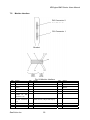
1
Document No. 6100084-03
TM
VREngine /SMD Series
High Resolution Graphics Board
User’s Manual
Manual version 3.1b
RealVision Inc.
VREngine/SMD Series Users Manual
FCC Notice
Federal Communications Commission
This equipment has been tested and found to comply with the limits for a Class A
digital device, pursuant to part 15 of the FCC Rules. These limits are designed to
provide reasonable protection against harmful interference in a residential
installation. This equipment generates, uses, and can radiate radio frequency
energy and, if not installed and used in accordance with the instruction manual,
may cause harmful interference to radio or television communications. However,
there is no guarantee that interference will not occur in a particular installation. If
this equipment does cause harmful interference to radio or television reception,
which can be determined by turning the equipment off and on, the user is
encouraged to try to correct the interference by one or more of the following
measures:
• Reorient or relocate the radio or television receiving antenna.
• Move the computer or equipment away from the receiver.
• Plug the computer or equipment into an outlet on a circuit different from that
which the radio or television receiver is connected.
• Consult the dealer or an experienced radio/TV technician for help.
CE Statement
This is Class A product. In a domestic environment this product may cause radio
interface in which case the user may be required to take adequate measures.
Copyright Notice
Copyright © 2001-2005 RealVision Inc. All Rights Reserved.
This document, as well as the hardware and software products described or
referenced in this document, are confidential and proprietary products of RealVision
Inc. They are provided under, and subject to, the terms and conditions of a written
license agreement between RealVision and its customers, and may not be
transferred, disclosed or otherwise provided to third parties, unless otherwise
permitted by that agreement.
RealVision Inc.
2
VREngine/SMD Series Users Manual
VREngineTM/SMD Series
High Resolution Graphics Board
User’s Manual version 3.1b
RealVision Inc.
3-1-1 Shin-Yokohama, Kōhoku-ku, Kanagawa 222-8505, Japan
Tel: +81-45-473-7331 Fax: +81-45-471-7330
http://www.realvision.co.jp/ http://www.rvu-inc.com/
All rights reserved.
RealVision Inc.
3
VREngine/SMD Series Users Manual
Introduction
Thank you for purchasing a VREngine/SMD Series product.
RealVision’s high-resolution graphics boards target the demands of imaging
applications and support high-resolution LCD monitors.
These PCI Bus graphics boards are specifically designed to deliver the highest quality
visual images on 2-megapixel, 3-megapixel and 5-megapixel LCD monitors.
The VREngine/SMD Series includes the following four products.
Table 1 VREngine/SMD Series lineup
Product Name
Specifications
Graphics board for single-link 2-megapixel grayscale and
VREngine/SMD2-PCI
color LCD monitors.
Graphics board for single-link 2- and 3-megapixel grayscale
VREngine/SMD3-PCI
and color LCD monitors
Graphics board for dual-link 3-megapixel grayscale and
VREngine/SMD3-DUL
color LCD monitors
Graphics board for single-link 2-, 3- and 5-megapixel
VREngine/SMD5-PCI
grayscale and color LCD monitors.
For information regarding LCD monitors, or related matters, please contact your
vendor or display manufacturer.
About This Manual
Please read through this manual before you install or use your “VREngine/SMD
Series” board.
This manual provides detailed information on how to install and configure your
VREngine/SMD Series high-resolution display controller. For information
regarding your computer monitor, or other attached devices not associated with
RealVision, Inc. please consult the user’s manuals or contact your device vendor.
Keep this manual conveniently located so that you can review to it as needed. If
you need a replacement manual please contact your vendor.
Please be sure to include the manual with the board if you transfer it to a third
party.
The information in this manual is subject to change without notice.
RealVision Inc.
4
VREngine/SMD Series Users Manual
Trademarks
VGA is a Registered Trademark of IBM Corporation.
VREngine is a Trademark of RealVision Inc.
All other trademarks are the property of their respective owners.
Safety precautions
This product is manufactured with all due care, but failure to exercise care during or
incorrect operation may lead to accidents. In order to avoid such problems, please use
the product only after reading and understanding this manual thoroughly.
RealVision Inc.
5
VREngine/SMD Series Users Manual
Contents
Introduction ·················································································································4
About This Manual ······································································································4
Trademarks ··················································································································5
Safety precautions ······································································································5
Contents·······················································································································6
1.
Product Overview··························································································7
2.
Installation Overview ····················································································7
3.
Installing the VREngine/SMD Board····························································8
3.1.
Installation notes···························································································8
3.2.
DIP-switch settings ·······················································································9
3.3.
Inserting the board························································································9
3.4.
Connecting monitors ··················································································11
4.
Installing the Driver Software·····································································12
5.
Monitor And Display Settings ····································································20
5.1.
Display Properties·······················································································20
5.1.1.
Color quality settings··············································································23
5.1.2.
Screen resolution settings······································································23
5.2.
VREngine advanced settings ·····································································24
5.2.1.
Color/Palette settings··············································································26
5.2.2.
Screen Update settings···········································································27
5.3.
Multi-Monitor settings·················································································28
5.4.
Detailed display adaptor and driver information······································37
5.5.
Monitor reconfiguration, driver update and uninstall ······························40
6.
How to Uninstall the Driver Software ························································41
7.
Product Information····················································································44
8.
Limited Warranty·························································································53
9.
Disposing of the product············································································53
RealVision Inc.
6
VREngine/SMD Series Users Manual
1. Product Overview
The VREngine/SMD Series package contains the following:
Graphics board
Driver & Installer CD-ROM
User’s Manual
Contact your local supplier if any of these items are missing.
Save the box and packing in case you need to return the board to your supplier
for any reason. Shipping damage is not covered under the warranty.
2. Installation Overview
The installation process involves the following steps:
Configure the board DIP switch settings as required
Install the board into the host system
Connect the LCD monitor(s) to the DVI outputs
Power on the host system
Manually install the driver software
Reboot the host system
Set any remaining Display Properties appropriately
RealVision Inc.
7
VREngine/SMD Series Users Manual
3. Installing the VREngine/SMD Board
This chapter describes how to install the VREngine/SMD board in your computer. If
necessary, please refer to the User’s Manual included with the computer.
3.1.
Installation notes
Please take note of the following when installing the VREngine/SMD series LCD
monitor graphics board into your system.
We recommended that you ask your vendor to install the VREngine/SMD Series
into your computer.
Do not touch the connectors, IC/LSI pins or exposed PCB tracks directly, as the
electronic devices used may be damaged by electro-static discharge.
Before installing the board, please clean your hands of any dirt or oil to avoid
danger of slipping.
Keep any parts that were not used during installation, as they may be of use for
future installations.
Before connecting cables, ensure there are no broken connectors or contacts or
bent connector pins, and no rubbish or dirt fouling the connectors. Use of broken
pins or dirty cables could result in a short circuit leading to fire.
Take care not to break the connectors by dropping them on the floor or elsewhere,
and not to drag cables on the floor or do anything else that might damage them or
make them dirty.
Fasten connector lock screws tightly, and take care not to drop them or strip the
thread. Failure to tighten them correctly could result in a short circuit leading to
fire.
Do not subject cables to heat or mechanical stress such as standing on or placing
heavy weights on them. When removing cables, unfasten the lock screws and
then pull straight out, holding the connector not the cable. Applying heat or
mechanical stress, twisting connectors, or tugging on the cable itself, may cause
damage to the cable or the connector, and degradation of the insulating sheath
could result in a short circuit.
This graphics board is for use only with personal computers with:
UL approval.
A manual with detailed instructions for customer installation of card-cage
accessories.
RealVision Inc.
8
VREngine/SMD Series Users Manual
3.2.
DIP-switch settings
The VREngine/SMD’s VGA output format is controlled by DIP-switches located on the
corner of the board as shown in Fig. 1.
Fig. 1 Front side of a VREngine/SMD
Unless advised otherwise by your monitor vendor, confirm that the DIP-switches are
initially set as in Fig. 2. With these settings, the VGA signal is automatically
determined using the EDID data read from the monitor during initialization.
Fig. 2 VGA output setting for an EDID compatible monitor.
3.3.
1.
Inserting the board
Ensure that your computer and any peripheral devices connected to it are
completely turned off.
N.B. The internal parts of your computer are still very hot just after being turned off.
Wait until everything cools off before starting the installation.
2.
Follow the instructions in your computer’s user manual to remove its cover.
RealVision Inc.
9
VREngine/SMD Series Users Manual
3.
Follow the instructions in your computer’s user manual to install the board into an
empty PCI slot. For best performance, use a PCI-X slot if one is available.
If the target slot has a dust cap, remove it.
Remove any screws or clips securing the rear cover of the PCI slot. They will
be used to secure the graphics board.
Confirm the DIP-switch settings on the front of the board in the top rear corner
opposite the connectors (see page 9).
Insert the edge connector of the board into the PCI slot slowly with care.
Make sure that the board is inserted firmly, and then secure the rear panel
using any screws or clips removed above.
Confirm that the board appears to be seated properly.
N.B. If the board is not properly seated, you should remove it from the slot completely
and insert it again from scratch. Do not use excessive force to insert or remove the
board to avoid damage to the cables, connectors or the board itself.
AGP Bus slot
33MHz PCI Bus slot
33MHz PCI Bus slot
PCI-X Bus slot
PCI-X Bus slot
PCI-X Bus slot
Fig. 3 Host system with various slot types
Fig. 3 above shows a photograph of an example host system with 2 different PCI Bus
slot types. Two 33MHz-PCI-bus slots and three PCI-X-bus slots are available. The
type, order and number of slots depend on the workstation used.
You can install VREngine/SMD series boards into 33MHz PCI, 66MHz PCI and PCI-X
slots. The VREngine/SMD products are designed to operate at 66MHz, so they
provide best performance when installed into 66MHz PCI or PCI-X slots.
RealVision Inc.
10
VREngine/SMD Series Users Manual
3.4.
Connecting monitors
When connecting your LCD monitor(s), please refer the following notes, and also
follow any special instructions provided by the monitor vendor.
Connecting a board to one monitor:
Connect the monitor to DVI Connector 1 (nearest the PCI Bus connector). If you
use DVI Connector 2, no image will be displayed
Fig. 4 Board connected to one monitor
Connecting a board to two monitors:
The driver settings allow a great deal of flexibility in monitor arrangement (see
page 28), but for simplest operation connect the left-hand monitor to DVI
Connector 1 (nearest the PCI Bus connector) and the right-hand monitor to DVI
Connector 2 (furthest from the PCI Bus connector).
Fig. 5 Board connected to two monitors
RealVision Inc.
11
VREngine/SMD Series Users Manual
4. Installing the Driver Software
This chapter describes how to install the VREngine/SMD Series driver software.
After installing the hardware, power on, start Windows, and login as administrator
or to another account with administrator privileges. You must have administrator
privileges in order to install the driver.
The Found New Hardware Wizard dialog will appear. Click the Cancel button. The
dialog will be displayed once for each newly installed board.
N.B. It is important that you do not allow the Found New Hardware Wizard to install
the driver automatically.
Fig. 6 Found New Hardware Wizard dialog
Insert the VREngine/SMD Driver CD-ROM into your CD-ROM drive. The driver
installation wizard should start automatically. If the installation does not start
automatically, open the CD-ROM (via Windows Explorer or My Computer) and
double-click the Setup application icon to start.
RealVision Inc.
12
VREngine/SMD Series Users Manual
The InstallShield Wizard welcome dialog will appear. Click the Next button.
Fig. 7 InstallShield Wizard welcome dialog
The License Agreement dialog box will appear. Review the license terms, and
click the Yes button if you accept them. If you click the No button, the installation
will terminate.
Fig. 8 License Agreement
RealVision Inc.
13
VREngine/SMD Series Users Manual
One of the following two dialog boxes will appear. Confirm the number of boards
detected, and click the OK button.
Fig. 9 Board detection dialogs
RealVision Inc.
14
VREngine/SMD Series Users Manual
The Number of monitors dialog in Fig. 10 will appear. Confirm the board type has
been correctly detected, select the number of monitors connected to the board,
and click the Next button.
Check
Select
Click
Fig. 10 Select number of monitors dialog
RealVision Inc.
15
VREngine/SMD Series Users Manual
The installer tries to match each connected monitor with its list of known monitor
types. If it succeeds, it skips directly to the Start Copying Files dialog in Fig. 14. If
it cannot match one or more monitors, the Monitor selection dialog will appear.
Select the type of Monitor 1 from the list.
Select
Fig. 11 Monitor selection dialog
N.B. If a monitor has been partly identified, a subset of the list may be displayed. You
can force the complete list to be displayed by selecting “Show All Monitors”.
If there are 2 monitors connected to the board, repeat the selection process for
Monitor 2.
Fig. 12 Selection of second monitor type
RealVision Inc.
16
VREngine/SMD Series Users Manual
Once all monitors are configured, check the Description, Resolution and Type in
the Information panels, and click the Next button to proceed.
Check
Fig. 13 Confirm selected monitor type(s)
If you have installed 2 VREngine/SMD graphics boards, the Number of monitors and
Monitor selection dialogs are displayed once for each board. Repeat the steps above
for the second board.
N.B. The list of available monitors varies from vendor to vendor, and may not match
the above illustrations exactly.
RealVision Inc.
17
VREngine/SMD Series Users Manual
The settings review dialog shown below will appear. After confirming all the
settings are correct, click the Next button to begin the driver installation. Click the
Back button if you need to correct any settings.
Fig. 14 Start Copying Files dialog
On Windows XP the Hardware Installation dialog will appear, warning you that the
driver is not digitally signed under the Windows Logo testing program. Click on the
Continue Anyway button to proceed. The dialog will appear once for each
VREngine/SMD graphics board.
Fig. 15 Windows XP Windows Logo warning dialog
On Windows 2000 the Digital Signature Not Found dialog is displayed once for
each monitor, rather than once for each board. Click the Yes button to continue
the installation in each case.
If multiple monitors are installed, a dialog giving you the opportunity to configure
the multi-monitor settings will appear. If you want the driver to present each
RealVision Inc.
18
VREngine/SMD Series Users Manual
monitor to the Windows desktop independently there is no need to configure
multi-monitor settings.
Go to multi-monitor settings
Finish installation
Fig. 16 Multi-monitor configuration
If you click the Yes button, refer to section 5.3 on page 28 for information on
multi-monitor configuration.
InstallShield Wizard Complete dialog will appear. Select Yes, I want to restart my
computer now, and click the Finish button. You must reboot before you can
peform the final stages of configuration.
Fig. 17 InstallShield Wizard Complete dialog
N.B. If you add additional boards, or move a board to a different PCI slot, you must
un-install and reinstall the driver software from scratch.
When multiple graphics boards are installed, the BIOS on some motherboards may fail
to boot correctly. As a workaround to this problem, try rearranging the boards in
different slots, so that system detects them in a different order. If the problem is still not
resolved, contact your vendor for further advice.
RealVision Inc.
19
VREngine/SMD Series Users Manual
5. Monitor And Display Settings
This chapter describes how to configure the display properties once installation is
complete.
5.1.
Display Properties
Open the Display Properties control panel. Choose Control Panel from the Start
menu, and double click on Display.
Fig. 18 Control Panel
If the Control Panel is in Category View, click on Appearance and Themes, then click
on Display in the sub-list of control panels, or click on Switch To Classic View to
display the full list of available control panels.
RealVision Inc.
20
VREngine/SMD Series Users Manual
You can also right-click on any empty part of your desktop and select Properties from
the pop-up menu to show the Display Properties panel.
Click the Settings tab to display the dialog shown in Fig. 20.
Fig. 19 Display Properties
Fig. 20 Settings tab
RealVision Inc.
21
VREngine/SMD Series Users Manual
Fig. 20 shows an example configuration with a monitor connected to the host system’s
primary display adapter (which may be on the motherboard, or in an AGP, PCI or
PCI-eXpress slot), and a 2nd Monitor connected to a VREngine/SMD series board.
The driver for the VREngine/SMD board has been installed, but the board is not yet
configured. The connected monitor displays nothing, and the monitor icon in the
Settings tab is grayed out.
If there is no other display adaptor, and only one VREngine/SMD series board is
installed, there will be no 2nd display icon, and the 1st monitor icon will be the monitor
connected to VREngine/SMD Series board.
Click the appropriate monitor icon to select the VREngine/SMD board for
configuration.
Click
Fig. 21 Select monitor
RealVision Inc.
22
VREngine/SMD Series Users Manual
If it is not already checked, click the “Extend my Windows desktop onto this
monitor” checkbox, and click Apply, to enable the display on the monitor.
Fig. 22 Extend desktop
5.1.1. Color quality settings
When using a color monitor, you can choose Medium (16 bit) or Highest (32 bit) as
normal.
When using “24-bit color conversion grayscale” mode (see Color/palette on page 26
below) with a grayscale monitor, you can select only Highest (32 bit).
When using the 8-bit grayscale modes, you can select only Low (8 bit). In 10-bit
grayscale modes you can select only Medium (16 bit).
5.1.2. Screen resolution settings
When using a color monitor, or a grayscale monitor in “24-bit color conversion
grayscale” mode, you can select the desired resolution using the Screen resolution
slider as normal.
When using the 8-bit grayscale modes under Windows XP, the Screen resolution slider
is disabled. Set your desired resolution as follows:
Click on the Advanced button to display the Monitor and Adaptor Advanced
Settings dialog
In the Adaptor tab, click the “List all modes” button to display the list of
available modes.
Select your chosen resolution and orientation, and click OK.
RealVision Inc.
23
VREngine/SMD Series Users Manual
5.2.
VREngine advanced settings
Click on the Advanced button in the Display Properties dialog to display the
Monitor and Adaptor Advanced Settings dialog.
Fig. 23 Advanced Settings dialog
RealVision Inc.
24
VREngine/SMD Series Users Manual
Click on the VREngine/MD Series tab to configure the Color/palette settings and
Screen update settings for the selected monitor.
Fig. 24 Mode settings tab
Color/palette and Screen update
See below.
Apply to all displays
If you are using multiple monitors and all installed monitors are the same model, this
checkbox will be enabled. When it is checked you can modify the Mode settings for all
the monitors at the same time.
Multi-Monitor Settings
Click this button to access the Multi-Monitor settings control panel. See page 28.
When using multiple monitors, unless the Apply to all displays checkbox is enabled,
you must return to the Display Properties dialog and select each monitor in turn to
configure it.
N.B. Parameter changes are applied to each monitor when you click the OK button or
the Apply button, but they do not take effect until the system is restarted.
RealVision Inc.
25
VREngine/SMD Series Users Manual
5.2.1. Color/Palette settings
Fig. 25 Color/Palette settings for grayscale monitors
Lists a selection of palettes suitable for the installed monitor. The full list of available
modes is as follows.
8-bit linear grayscale palette
256 shades of gray (the default).
8-bit non-linear grayscale palette
Reserves the first and last 10 entries for the system palette, and makes a
linear palette of the remaining 236 entries.
8-bit dynamic grayscale palette
Allows the palette to be dynamically controlled by other programs.
8-/16-/24-bit color
The standard windows color quality Highest (32 bit) and Medium (16 bit)
settings are available in the Display Properties dialog.
10-bit grayscale
1024 shades of gray.
24-bit color conversion grayscale
In this mode VREngine/SMD board displays monitor(s) allows the Operating
System to output 24-bit color as normal, and down-samples it to 1024 levels of
gray for display.
30-bit color
1024 shades for each of RGB; 1,073,741,824 colors in total.
RealVision Inc.
26
VREngine/SMD Series Users Manual
5.2.2. Screen Update settings
Fig. 26 Screen Update settings
There are three screen update modes which affect the speed and quality of display:
High-speed
Updates the screen in blocks for fastest drawing. With some applications you
may experience staircase-shaped after-images. If this is a problem, please
select another mode.
Standard
Attempts a trade-off between high-speed and high-quality.
High-quality
Updates the whole screen at once. Provides the smoothest, slowest, display,
with no after-images.
RealVision Inc.
27
VREngine/SMD Series Users Manual
5.3.
Multi-Monitor settings
Open the Display Properties control panel. Choose Control Panel from the Start
menu, and double click on VREngine/MD Series.
Fig. 27 Control Panel
If the Control Panel is in Category View, click on Appearance and Themes, then click
on Display in the sub-list of control panels, or click on Switch To Classic View to
display the full list of available control panels.
RealVision Inc.
28
VREngine/SMD Series Users Manual
A dialog similar to the following will appear (this dialog shows an example with
one VREngine/SMD Series board and 2 monitors installed in the All-Independent
setting).
Fig. 28 Multi-Monitor tab
Each monitor connected to a VREngine/SMD Series board is given a letter in
sequence: A, B, C… The numbering scheme in the Display Properties dialog is not
used.
RealVision Inc.
29
VREngine/SMD Series Users Manual
Click on a monitor symbol to show the configuration information for each monitor.
The identifying letter of the selected monitor is shown in black.
Information
Fig. 29 Monitor Information
The following information is displayed
Description
Shows the monitor type as selected in the installer.
Resolution
The monitor resolution.
Color type
Grayscale or color.
Connection
Shows the VREngine/SMD Series board number and monitor number.
RealVision Inc.
30
VREngine/SMD Series Users Manual
The VREngine/SMD Series boards allow you to combine multiple monitors into one
virtual monitor.
The sequence for adding a new monitor to a virtual monitor group is as follows.
Select a monitor to connect.
Right-click on it to show the monitor connection menu.
Choose the appropriate connection direction or type.
Choose the target monitor from the sub menu.
The selected monitor is connected to the chosen target monitor.
Fig. 30 Monitor connection menu
RealVision Inc.
31
VREngine/SMD Series Users Manual
Combined monitors are shown joined by a dotted line as in the following dialog:
Fig. 31 Two monitors combined
Connect to the Right
Connect to the Right joins the selected monitor to the right-hand side of the target
monitor. In the following example, Display B will be connected to right-hand side of
Display A, creating a single virtual monitor.
Fig. 32 Connect to the Right
RealVision Inc.
32
VREngine/SMD Series Users Manual
Connect to the Bottom
Connect to the Bottom joins the selected monitor to the bottom of the target monitor. In
the following example, Display B will be connected to bottom of Display A, creating a
single virtual monitor.
Fig. 33 Connect to the Bottom
Clone
Clone sets the selected monitor to display a clone of the same image as the target
monitor. In the following example, Display B will mirror the contents of Display A.
Fig. 34 Clone
RealVision Inc.
33
VREngine/SMD Series Users Manual
Once monitors have been cloned, a pop-up menu appears in the top-right of the
dialog. You can use this menu to select which monitor’s information to display in the
dialog.
Fig. 35 Clone mode
Independent
Independent disconnects the selected monitor from its connected monitor(s). It is not
available if the monitor is not connected to any other monitors.
Fig. 36 Independent
N.B. The new settings are stored when you click OK or Apply, but are not immediately
activated. When you change the settings, a dialog will appear asking whether you
want to reboot your workstation. Changes are activated following the next reboot.
RealVision Inc.
34
VREngine/SMD Series Users Manual
As an alternative to configuring monitors individually, some common preset settings
are provided. The supported presets are All-Independent, Unified, and All-Unified.
Fig. 37 Multi-monitor presets
All-Independent
Click on the All-Independent button to use all the monitors connected to
VREngine/SMD Series boards independently. Clicking this button destroys any
connections previously made between monitors.
Fig. 38 All-Independent
RealVision Inc.
35
VREngine/SMD Series Users Manual
Unified
Click on the Unified button to group pairs of monitors connected to the same
VREngine/SMD Series board into one virtual monitor per board. Clicking this button
destroys any connections previously made between monitors.
Fig. 39 Unified
All-Unified
Click on the All-Unified button to group all the monitors connected to VREngine/SMD
Series boards into one virtual wide monitor. Clicking this button destroys any
connections previously made between monitors. The All-Unified button is disabled
when there is only one VREngine/SMD Series board in the workstation.
Fig. 40 All-Unified
RealVision Inc.
36
VREngine/SMD Series Users Manual
5.4.
Detailed display adaptor and driver information
Open the Display Properties control panel. Choose Control Panel from the Start
menu, and double click on VREngine/MD Series.
Fig. 41 Control Panel
If the Control Panel is in Category View, click on Appearance and Themes, then click
on Display in the sub-list of control panels, or click on Switch To Classic View to
display the full list of available control panels.
RealVision Inc.
37
VREngine/SMD Series Users Manual
A dialog similar to the following will appear.
Fig. 42 Properties tab
Click on the Properties tab to display detailed information about the display
adaptor(s) and driver files.
Fig. 43 Detailed Information
RealVision Inc.
38
VREngine/SMD Series Users Manual
The following information is displayed
Display adapter information
Shows the product name, BIOS version, PCI bus location etc.
Driver information
Shows a list of driver files and their version numbers.
RealVision Inc.
39
VREngine/SMD Series Users Manual
5.5.
Monitor reconfiguration, driver update and uninstall
Insert the VREngine/SMD Driver CD-ROM into your CD-ROM drive. The driver
installation wizard should start automatically. If the installer does not start
automatically, open the CD-ROM (via Windows Explorer or My Computer) and
double-click the Setup application icon to start.
The InstallShield Wizard Reconfigure/Update/Uninstall dialog will appear.
Fig. 44 Reconfigure/Update/Ininstall
Choose the appropriate option and click the Next button.
Reconfigure monitor(s)
Select this option if you want to add new monitors or change existing monitor
type settings.
Update
Select this option if you want to update the driver software or add or remove a
VREngine/SMD Series board from the system. The installer uninstalls and
reinstalls the software as a single operation. For additional information related
to installation, see page 12.
Uninstall
Select this option if you want to uninstall the driver software. For additional
information on uninstallation see “How to Uninstall the Driver Software” below.
N.B. Choosing either Reconfigure monitor(s) or Update causes all previous settings,
including Multi-monitor settings, to be re-initialized.
RealVision Inc.
40
VREngine/SMD Series Users Manual
6. How to Uninstall the Driver Software
This section describes how to uninstall the driver software.
Choose Control Panel from the Start menu, and double click on the Add or
Remove Programs icon.
Fig. 45 Control Panel classic view
If the Control Panel is in Category View, click once on the Add or Remove Programs
category.
Fig. 46 Control Panel category view
RealVision Inc.
41
VREngine/SMD Series Users Manual
The Add or Remove Programs dialog will appear.
Fig. 47 Add/Remove Program
Click VREngine/MD Series Display Driver in the list of Currently installed
programs to highlight it.
Click the Change/Remove button. The dialog below appears. Click Yes to begin
the uninstallation process.
Fig. 48 Confirm uninstallation
N.B. You will have to reboot your workstation to complete the uninstallation. Before
you begin uninstalling, terminate all other running applications.
RealVision Inc.
42
VREngine/SMD Series Users Manual
When the following dialog is displayed, click Yes to reboot your system and
complete the uninstallation.
Fig. 49 Confirm reboot
RealVision Inc.
43
VREngine/SMD Series Users Manual
7. Product Information
7.1.
Technical Specification (VREngine/SMD2-PCI)
Operating Conditions
Host system
Operating systems
Host processor
Operating frequency
Host bus spec.
Mechanical Spec.
Host bus frequency
Size of main memory
Operating voltage
Power consumption
Board size (Outline)
Display Resolution
Weight
# of occupied slots
# of boards
Single-monitor
Connectable Monitors Note 1
2M VESA-compliant digital LCD
monitors
Other 2M digital LCD monitors
Max 2
Landscape
Portrait
VGA standard compliant
# of connectable monitors
Display Modes Note 2
VGA display function Note 3
Built-in
Display bit depth
Display memory size
Video Output Signal Note 4
Video Output Spec.
Certification
Operating Temperature
Storage Conditions
DVI (Digital Visual
Interface)
Max Dot Clock
Temp. & Humidity
Altitude
RealVision Inc.
IBM PC compatible
Windows 2000 Professional
Windows XP
Intel IA32
>500MHz
PCI 32-bit, 5V / 3.3V
(PCI 2.2 compliant)
33Mhz, 66MHz
>256Mbytes
5V ±0.25V
16.8W (max)
174.5 (W) x 106.7 (H) mm or
7.1 (W) x 4.2 (H) inch
160g / 0.34lbs
PCI bus slot x1
PCI board x1
1600 x 1200 pixel (Landscape)
1200 x 1600 pixel (Portrait)
44
8-bit/pixel grayscale
10-bit/pixel grayscale
8-, 24-bit/pixel color
128Mbytes DDR-SDRAM
DVI-D
165MHz
UL/cUL, FCC, CE
1–35°C / 50–95°F
-20–75°C / -4–167°F
5%–100% (Non-condensing)
Up to 11,000m / 36,000ft
VREngine/SMD Series Users Manual
Note 1) EDID provides compatibility for monitors not compliant with 2M VESA.
Note 2) Supported display modes are as follows:
Portrait
Landscape
Unified
All Independent
Fig. 50 VREngine/SMD2-PCI Display Mode Settings
Note 3) VGA mode can be displayed enlarged. Portrait VGA display is also supported.
Note 4) Video output is not used as a power source.
RealVision Inc.
45
VREngine/SMD Series Users Manual
7.2.
Technical Specification (VREngine/SMD3-PCI)
Operating Conditions
Host system
Operating systems
Host processor
Operating frequency
Host bus spec.
Mechanical Spec.
Host bus frequency
Size of main memory
Operating voltage
Power consumption
Board size (Outline)
Display Resolution
Weight
# of occupied slots
# of boards
Single-monitor
Connectable Monitors
# of connectable monitors
Display Modes Note 1
VGA display function Note 2
Built-in
VGA standard compliant
Display bit depth
Display memory size
Video Output Signal Note 3
Video Output Spec.
Certification
Operating Temperature
Storage Conditions
DVI (Digital Visual
Interface)
Max Dot Clock
Temp. & Humidity
Altitude
RealVision Inc.
IBM PC compatible
Windows 2000 Professional
Windows XP
Intel IA32
>500MHz
PCI 32-bit, 5V / 3.3V
(PCI 2.2 compliant)
33Mhz, 66MHz
>256Mbytes
5V ±0.25V
16.8W (max)
174.5 (W) x 106.7 (H) mm or
7.1 (W) x 4.2 (H) inch
160g / 0.34lbs
PCI bus slot x1
PCI board x1
2048 x 1536 pixel (Landscape)
1536 x 2048 pixel (Portrait)
2M digital LCD monitors
3M digital LCD monitors
Max 2
Landscape
Portrait
46
8-bit/pixel grayscale
10-bit/pixel grayscale
8-, 24-bit/pixel color
128Mbytes DDR-SDRAM
DVI-D
165MHz
UL/cUL, FCC, CE
1–35°C / 50–95°F
-20–75°C / -4–167°F
5%–100% (Non-condensing)
Up to 11,000m / 36,000ft
VREngine/SMD Series Users Manual
Note 1) Supported display modes are as follows:
Landscape
Portrait
Unified
All Independent
Fig. 51 VREngine/SMD3-PCI Display Mode Settings
Note 2) VGA mode can be displayed enlarged. Portrait VGA display is also supported.
Note 3) Video output is not used as a power source.
RealVision Inc.
47
VREngine/SMD Series Users Manual
7.3.
Technical Specification (VREngine/SMD3-DUL)
Operating Conditions
Host system
Operating systems
Host processor
Operating frequency
Host bus spec.
Mechanical Spec.
Host bus frequency
Size of main memory
Operating voltage
Power consumption
Board size (Outline)
Display Resolution
Weight
# of occupied slots
# of boards
Single-monitor
Connectable Monitors
# of connectable monitors
Display Modes Note 1
VGA display function Note 2
Built-in
VGA standard compliant
Display bit depth
Display memory size
Video Output Signal Note 3
Video Output Spec.
Certification
Operating Temperature
Storage Conditions
DVI (Digital Visual
Interface)
Max Dot Clock
Temp. & Humidity
Altitude
RealVision Inc.
IBM PC compatible
Windows 2000 Professional
Windows XP
Intel IA32
>500MHz
PCI 32-bit, 5V / 3.3V
(PCI 2.2 compliant)
33Mhz, 66MHz
>256Mbytes
5V ±0.25V
16.8W (max)
174.5 (W) x 106.7 (H) mm or
7.1 (W) x 4.2 (H) inch
160g / 0.34lbs
PCI bus slot x1
PCI board x1
2048 x 1536 pixel (Landscape)
1536 x 2048 pixel (Portrait)
2M digital LCD monitors
3M digital LCD monitors
Max 2
Landscape
Portrait
48
8-bit/pixel grayscale
10-bit/pixel grayscale
8-, 24-bit/pixel color
128Mbytes DDR-SDRAM
DVI-D
130MHz
UL/cUL, FCC, CE
1–35°C / 50–95°F
-20–75°C / -4–167°F
5%–100% (Non-condensing)
Up to 11,000m / 36,000ft
VREngine/SMD Series Users Manual
Note 1) Supported display modes are as follows:
Landscape
Portrait
Unified
All Independent
Fig. 52 VREngine/SMD3-DUL Display Mode Settings
Note 2) VGA mode can be displayed enlarged. Portrait VGA display is also supported.
Note 3) Video output is not used as a power source.
RealVision Inc.
49
VREngine/SMD Series Users Manual
7.4.
Technical Specification (VREngine/SMD5-PCI)
Operating Conditions
Host system
Operating systems
Host processor
Operating frequency
Host bus spec.
Mechanical Spec.
Host bus frequency
Size of main memory
Operating voltage
Power consumption
Board size (Outline)
Display Resolution
Weight
# of occupied slots
# of boards
Single-monitor
Connectable Monitors
# of connectable monitors
Display Modes Note 1
VGA display function Note 2
Built-in
VGA standard compliant
Display bit depth
Display memory size
Video Output Signal Note 3
Video Output Spec.
Certification
Operating Temperature
Storage Conditions
DVI (Digital Visual
Interface)
Max Dot Clock
Temp. & Humidity
Altitude
RealVision Inc.
IBM PC compatible
Windows 2000 Professional
Windows XP
Intel IA32, AMD, etc.
>500MHz
PCI 32-bit, 5V / 3.3V
(PCI 2.2 compliant)
33Mhz, 66MHz
>256Mbytes
5V ±0.25V
16.8W (max)
174.5 (W) x 106.7 (H) mm or
7.1 (W) x 4.2 (H) inch
160g / 0.34lbs
PCI bus slot x1
PCI board x1
1600 x 1200 pixel (Landscape)
1200 x 1600 pixel (Portrait)
2M digital LCD monitors
3M digital LCD monitors
5M digital LCD monitors
Max 2
Landscape
Portrait
50
8-bit/pixel grayscale
10-bit/pixel grayscale
8-, 24-bit/pixel color
128Mbytes DDR-SDRAM
DVI-D
165MHz
UL/cUL, FCC, CE
1–35°C / 50–95°F
-20–75°C / -4–167°F
5%–100% (Non-condensing)
Up to 11,000m / 36,000ft
VREngine/SMD Series Users Manual
Note 1) Supported display modes are as follows:
Portrait
Landscape
Using Unified
Using All Independent
Fig. 53 VREngine/SMD5-PCI Display Mode Settings
Note 2) VGA mode can be displayed enlarged. Portrait VGA display is also supported.
Note 3) Video output is not used as a power source.
RealVision Inc.
51
VREngine/SMD Series Users Manual
7.5.
Monitor interface
DVI Connector 2
DVI Connector 1
Bracket
Fig. 54 Monitor Interface
PIN
1
2
3
4
5
6
7
8
C1
C4
Signal
T.M.D.S. Data 2T.M.D.S. Data 2+
T.M.D.S. Data 2/4
Shield
T.M.D.S. Data 4T.M.D.S. Data 4+
DDC
Clock
(Output for DVI
connector 1,2)
DDC Data (Output
for DVI connector
1,2)
N.C.
N.C.
N.C.
RealVision Inc.
PIN
9
10
11
Signal
T.M.D.S. Data 1T.M.D.S. Data 1+
T.M.D.S. Data 1/3 Shield
PIN
17
18
19
12
13
14
T.M.D.S. Data 3T.M.D.S. Data 3+
+5V Power
20
21
22
Signal
T.M.D.S. Data 0T.M.D.S. Data 0+
T.M.D.S. Data 0/5
Shield
T.M.D.S. Data 5T.M.D.S. Data 5+
T.M.D.S. Clock Shield
15
Ground
(return for +5V, HSync and Vsync)
23
T.M.D.S. Clock+
16
C2
C5
Monitor Sense
N.C.
N.C.
24
C3
T.M.D.S. ClockN.C.
52
VREngine/SMD Series Users Manual
8. Limited Warranty
RealVision’s Standard high-resolution graphics board Warranty and Customer’s sole
and exclusive remedies for such warranties are specified below. REALVISION’S
WARRANTIES STATED IN THIS SECTION ARE IN LIEU OF ALL OTHER
WARRANTIES EXPRESSED, IMPLIED, OR STATUTORY, INCLUDING WITHOUT
LIMITATION, ANY WARRANTY OF MERCHANTABILITY OR FITNESS FOR A
PARTICULAR PURPOSE.
No statement, including without limitation, representations regarding capacity,
suitability for use or performance of Product(s), whether made by RealVision
employees or otherwise, shall be deemed to be a warranty by RealVision for any
purpose or give rise to any liability of RealVision unless expressly contained in this
Warranty.
The warranties in this section do not apply to any Product(s) which has been (i)
altered, except by RealVision or by another party adhering to RealVision’s instructions,
(ii) used in conjunction with another vendor’s product resulting in a defect, or (iii)
damaged by improper electrical power or environment, abuse, misuse, accident or
negligence.
RealVision warrants to Customer that the High resolution display controller covered by
the Standard High resolution display controller Warranty will be free from defects in
workmanship and materials for a period of thirty-six (36) months from the date of
purchase. For repairs after warranty period, please contact your local supplier.
9. Disposing of the product
When disposing of the product, please be sure follow all national and regional
regulations. For details, please contact your local government offices.
RealVision Inc.
53
VREngine/SMD Series Users Manual
RealVision Inc.
3-1-1, Shin-Yokohama, Kōhoku-ku, Yokohama, Kanagawa 222-8505, Japan
Tel: +81-45-473-7331
Fax: +81-45-473-7330
URL http://www.realvision.co.jp/
RVU, INC.
3080 Olcott Street, Suite 203-B, Santa Clara, CA 95054, USA
Tel: +1-408-845-9410
Fax: +1-408-845-9457
URL http://www.rvu-inc.com/
株式会社リアルビジョン
〒222-8505 神奈川県横浜市港北区新横浜 3-1-1
電話:045-473-7331
ファックス:045-473-7330
Copyright© 2001-2005 by RealVision Inc., all rights reserved.
RealVision Inc.
54