1
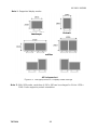
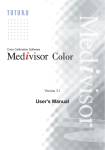
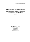
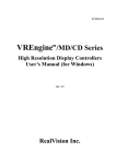
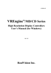
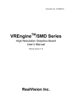
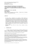
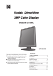
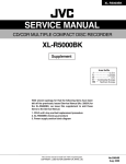
LV52P3/LV32P3
High Resolution Graphics Card
User’s Manual
TOTOKU ELECTRIC CO., LTD.
LV32P3 / LV52P3
FCC Notice
Federal Communications Commission
This equipment has been tested and found to comply with the limits for a Class A
digital device, pursuant to part 15 of the FCC Rules. These limits are designed to
provide reasonable protection against harmful interference in a residential installation.
This equipment generates, uses, and can radiate radio frequency energy and, if not
installed and used in accordance with the instruction manual, may cause harmful
interference to radio or television communications. However, there is no guarantee
that interference will not occur in a particular installation. If this equipment does
cause harmful interference to radio or television reception, which can be determined
by turning the equipment off and on, the user is encouraged to try to correct the
interference by one or more of the following measures:
• Reorient or relocate the radio or television receiving antenna.
• Move the computer or equipment away from the receiver.
• Plug the computer or equipment into an outlet on a circuit different from that which
the radio or television receiver is connected.
• Consult the dealer or an experienced radio/TV technician for help.
CE Statement
This is Class A product. In a domestic environment this product may cause radio
interface in which case the user may be required to take adequate measures.
About This Manual
Read through this manual before you install or use this product.
This manual provides detailed information on how to install and configure this
product. As for information regarding your computer display or other peripheral
devices that are not TOTOKU’s products, please refer to the respective user’s
manuals or consult their respective dealers.
Keep this manual in a safe and easily accessible place. In case of loss, contact your
dealer for another copy of this manual.
Attach this manual to the card when transferring to a third person.
This manual is subject to change without notice.
TOTOKU
2
LV32P3 / LV52P3
Contents
1. Overview···················································································4
2. Installation················································································5
2.1 Setting up DIP Switches ·························································6
2.2 Installing LV52P3/LV32P3 ······················································7
2.3 Connecting to the Display ·······················································8
3. Installing Driver Software ···························································9
4. Setting up the Display ······························································· 17
4.1 Display Properties ································································ 17
4.2 Advanced Settings
4.2.1 Color/Palette ································································· 22
4.2.2 Screen Update································································ 22
4.3 Multi Monitor Setting···························································· 23
4.4 Adaptor and Driver Information ············································· 31
4.5 Reconfiguring, Updating, and Uninstalling ······························· 32
5. Uninstalling Driver Software ······················································ 34
6. Technical Specifications
6.1 LV32P3··············································································· 36
6.2 LV52P3··············································································· 38
6.3 Display Interface ································································· 40
7. Disposing of the Product ··························································· 40
TOTOKU
3
LV32P3 / LV52P3
1. Overview
Thank you for purchasing graphics card LV52P3 or LV32P3. TOTOKU’s high-resolution
PCI bus graphics cards are designed to deliver the highest quality visual images on 2,
3, and 5-megapixel LCD displays to meet market demands.
The following table shows the products names and their supporting displays.
Product Name
LV32P3
LV52P3
Supported Displays
3 megapixel monochrome and color LCD displays:
・ CCL316
・ ME315L
・ ME315L plus
5 megapixel monochrome and color LCD Displays
For more information regarding LCD displays and/or related matters, please contact
your dealer.
This package contains the following items. Contact your dealer if any item is missing.
Graphics Card LV52P3 or LV32P3
Driver & Installer CD-ROM
User’s Manual
Note: Save the original box and packing manual to pack the product for shipping.
Damages occurred during shipping are not covered under the warranty.
TOTOKU
4
LV32P3 / LV52P3
2. Installation
This chapter explains how to install LV52P3 or LV32P3. Refer to the computer
instruction manual as necessary.
Make sure to follow the procedures as indicated below to successfully install the
graphics card and its software.
1)
2)
3)
4)
5)
6)
7)
Set up the DIP switches
Install the card
Connect the display(s)
Turn on the computer
Install driver software
Set up the display properties
Restart the computer
Before installing …
If you do not know how to install, ask your dealer to install it.
Do not touch connectors, IC/LSI pins, and/or terminals on the card. Static
electricity could damage them.
Handle the card with clean hands. Grease on your hands could cause the product
to slip off.
Keep any parts that become unnecessary for future use.
Make sure that connectors, connector pins, and contacts are not damaged,
deformed, or stained. Dust off before use. They could cause short circuits and fire.
Handle the connectors carefully to prevent damage from dropping and keep them
clean.
Be careful not to drop any fasteners inside the computer. It could cause a short
circuit and/or an open circuit.
Do not expose the cables to heat; do not put heavy objects on the cables. They
could damage the cables and cause fire. To disconnect a cable, undo the screws on
the connector and pull straight by holding the connector.
Use this product only on supported UL-listed computers.
TOTOKU
5
LV32P3 / LV52P3
2.1. Setting up DIP Switches
The DIP switches control output formats. The switches are set for EDID compatible
displays by default. Consult your dealer to find out whether or not your display is
EDID compatible.
Figure 2.1 LV52P3/LV32P3
Disabling VGA Output
To disable VGA output through the card, turn switch 3 to zero. Set up all LV52P3’s or
LV32P3’s the same way.
Figure 2.2 VGA Output Disabled
Enabling VGA Output on EDID compatible displays
To enable VGA Output on an EDID compatible display, turn switches 1 and 3 to zero
as shown in Figure. 3.3, and the card detects display information through EDID and
selects method of displaying VGA output automatically.
Note: Some EDID compatible displays do not support this setting. Contact your dealer
and find out about this in advance.
Figure 2.3 VGA Output Disabled on EDID Compatible Displays
TOTOKU
6
LV32P3 / LV52P3
2.2. Installing LV52P3/LV32P3
Follow the instructions below on how to install the card.
1. Make sure to turn off your computer and peripheral devices.
Note: Careful, the internal parts of the computer may be very hot. Wait until they
cool off before starting installation.
2. Remove the computer cover (see the computer instruction manual if necessary).
3. Insert the card in a PCI slot.
1) If the subject PCI slot has a dust cap, remove it.
2) Undo the screws of the bracket for the PCI slot. Keep the screws for later use to
secure the graphics card to the slot.
3) Insert this card to the PCI slot slowly and carefully.
4) Insert the card firmly and secure it to the slot using the screws removed at step
2. Make sure that the card is now installed properly.
Note:
・ If the card is not inserted properly, remove it once and insert it again. Do not
force to insert or remove the card, or it could damage the cables, connectors, or
the card itself.
・ LV52P3/LV32P3 support the following slots: 33MHz-PCI, 66MHz-PCI bus and
PCI-X bus. However, we recommend the 66MHz-PCI bus slot for the best
performance.
AGP Bus Slot
33MHz PCI Bus Slot
33MHz PCI Bus Slot
PCI-X Bus Slot
PCI-X Bus Slot
PCI-X Bus Slot
Figure 2.4 PCI Bus Slots
In Figure 2.4, two 33MHz-PCI-bus slots and three PCI-X-bus slots are available.
Depending on the computer, the number of available slots, their order, and their types
may vary. Use any slot when using only one LV52P3 or LV32P3.
TOTOKU
7
LV32P3 / LV52P3
2.3.
Connecting to the Display
Follow the instructions below on how to connect the LCD display(s) to the card. Refer
to the display instruction manual if necessary.
One Display on One Card
When connecting only one display, use DVI Connector 1 that is closer to the PCI bus.
DVI Connector 2 is for the secondary display.
Figure 2.5 One Display Connected to One Card
Two Displays on One Card
When connecting two displays, use DVI Connector 1 for the primary display (Display
1) and DVI Connector 2 for the secondary display (Display 2). When displays are
connected to the wrong connectors, the image will not be displayed properly.
Figure 2.6 Two displays connected to one card
TOTOKU
8
LV32P3 / LV52P3
3. Installing Driver Software
This chapter explains how to install driver software for LV52P3/LV32P3. Follow the
instructions below.
1. Turn on the computer and log into Windows as a user with administrative
privileges.
2. Click “Cancel” when the Found New Hardware Wizard starts up.
Figure 3.1 Found New Hardware
Figure 3.2 Welcome to the Found New Hardware Wizard
3. Insert the software driver CD-ROM in the CD-ROM drive, and the InstallShield
Wizard starts up automatically.
Note: If the wizard does not start automatically, run Setup.exe from the
CD-ROM.
TOTOKU
9
LV32P3 / LV52P3
4. Click “Next” on the wizard.
Figure 3.3 InstallShield Wizard
5. The License Agreement appears. Read the terms and conditions of the Agreement.
If you accept the Agreement, click “Yes.” If you do not accept the Agreement, click
“No,” and the wizard will terminate.
Figure 3.4 License Agreement
TOTOKU
10
LV32P3 / LV52P3
6. One of the following messages appears. Confirm the number of graphics cards
installed and click “OK.”
Figure 3.5 When a single card installed
Figure 3.6 When two cards installed
7. When the following screen appears, confirm the graphics card name and select
the number of displays connected to the card. Click “Next.”
Confirm
Select
Figure 3.7 Monitor Number Selection
TOTOKU
11
LV32P3 / LV52P3
8. When the following screen appears, select a display model and click “Next.”
Select
Figure 3.8 Monitor Selection - 1
Check
Figure 3.9 Monitor Selection - 2
TOTOKU
12
LV32P3 / LV52P3
Note: When two displays are connected, select them separately.
Figure 3.10 Monitor Selection - 3
9. When the following screen appears, confirm the contents and click “Next.”
Figure 3.11 Display Parameter Confirmation
Note: When installing multiple cards, repeat steps 7 through 9 for each card.
TOTOKU
13
LV32P3 / LV52P3
10. The following screen appears. The Current Settings field shows configuration
settings. Confirm the settings and click “Next,” and driver installation begins.
Note: To go back and change any settings, click “Back.”
Figure 3.12 Start Copying Files
11. When the following screen appears, click “Yes.” If you are using Windows 2000,
this screen appears for each display connected. If you are using Windows XP, this
screen appears for each card installed, regardless of the number of displays.
Figure 3.13 Digital Signature -1
TOTOKU
14
LV32P3 / LV52P3
Figure 3.14 Digital Signature -2
12. When multiple displays are connected, the following message appears. To use
displays independently, click “No.” To use them in stretched mode, click “Yes.”
Otherwise, click “No.”
Figure 3.15 Multi-Monitor Settings
TOTOKU
15
LV32P3 / LV52P3
13. When the following wizard appears, select “Yes, I want to restart my computer
now” and click “Finish.” The computer restarts itself.
Figure 3.16 InstallShield wizard Complete
Note: When adding a card or changing a PCI bus slot, uninstall the driver once
(see ”Uninstalling Driver Software”) and install it again.
When multiple cards are installed, the motherboard BIOS may cause boot failure. In
that case, try different slots. The cards will be detected in different order. If the
problem remains, consult your dealer.
TOTOKU
16
LV32P3 / LV52P3
4. Setting up the Display
This chapter explains how to set up the display(s). When multiple displays are
connected, set up each display separately.
4.1. Display Properties
1. Select Control Panel>Display Properties from the Start menu, and the
Display Properties dialog box appears.
Figure 4.1 Display Properties
2. Select the Settings tab.
Figure 4.2 Setting tab
Note:
・ The figure above is an example of the following configuration:
1st Display: Connected to the XGA Adapter on the motherboard or either on the
AGP bus or on the PCI bus
TOTOKU
17
LV32P3 / LV52P3
2 Display: Connected to LV52P3/LV32P3. Since it is not configured yet, the
display shows nothing.
・ When the computer has LV52P3/LV32P3 installed but without a display adapter, the
2nd display cannot exist. The 1st display will be the only display connected to
LV52P3/LV32P3.
nd
3. Select the icon for the 2nd display.
Click
Figure 4.3 Select Desktop
4. Select resolution using the slider in the Screen area section.
5. Select a pixel format in the Colors section.
(If you are using Windows XP, see the explanation below on “Advanced.”)
6. Check “Extend my Windows desktop onto this monitor.”
7. Click “Apply,” and the 2nd display comes on.
Select
Select
Figure 4.4 Desktop Configuration
TOTOKU
18
LV32P3 / LV52P3
For more information on the Settings tab settings, see the following explanations.
Colors
Color modes for monochrome displays
• “True Color (32bit)”: 24 bit Color Conversion Grayscale palette
• “256 Colors”: 8 bit color palette
Color modes for color displays:
“256 colors,” “High Color (16bit),” and “True Color (32bit).”
For more Information, see 5.2.1.
Screen Area
• 2560 x 2048: for 5 megapixel displays in landscape orientation
• 2048 x 2560: for 5 megapixel displays in portrait orientation
When 2- or 3 megapixel displays are connected, appropriate options appear.
Advanced: A dialog box for the Color/Palette and Screen Update settings
appears.
Note: Windows XP does not support 256 colors. If you are using Windows XP on a
monochrome display, follow the instructions below.
1) Click “Advanced” on the Settings tab in the Display Properties dialog box, and
the following screen appears.
Figure 4.5 Advanced Setting – 1
2) Select the Adapter tab and click “List All Modes,” and the list of available color
modes appears.
TOTOKU
19
LV32P3 / LV52P3
3) Select resolution and click “OK.”
4) Select the VREngine/MD Series tab. Set up the Color/Palette and the
Screen Update sections.
Figure 4.6 Advanced Setting - 2
See the following explanations for more information on the VREngine/MD Series
tab settings.
Color/Palette (For more information, see 5.2.1.)
Figure 4.7 Color/Palette setting for a monochrome display
TOTOKU
20
LV32P3 / LV52P3
Figure 4.8 Color/Palette setting for a color display
Screen Update (For more information, see 5.2.2.)
Figure 4.9 Screen Update setting
“Apply to all displays”
If you are using multiple displays that are all the same model, “Apply to All Displays”
should be active. Check this to apply the same settings to all displays at a time.
Note:
・ After clicking “Apply,” a message appears and asks you whether or not to restart
your computer. Click “Yes,” and your computer will be restarted.
・ “Adjust Dialog Position” should not be active.
“Multi Monitor Setting” Button: Click the button to configure multi-display
setup. For more information, see 5.3.
TOTOKU
21
LV32P3 / LV52P3
4.2. Advanced Settings
4.2.1. Color/Palette
Color Modes for Color Displays
• “256 Colors”: 8 bit color
• “High Color”: 16 bit color
• “True Color”: 24 bit Color
Color Modes for Monochrome Displays
• “8 bit linear grayscale palette mode”: 256 fixed palette grayscale from 0 to 255
• “8 bit non-linear grayscale palette mode”:
256 fixed palette grayscale. The first and last 10 shades are for the
system pallet and the remaining 236 shades are aligned in liner order.
• “8 bit variable grayscale palette mode”:
An application program selects variable 256 shades of gray.
• “24 bit color conversion grayscale palette”:
LV52P3/LV32P3 converts 24bit RGB-color into 10bit grayscale. The
operating system will not shut down during processing.
4.2.2. Screen Update
The Screen Update section contains three screen refresh rates as follows.
• High-Speed: Fastest rate among three choices. If the staircase-patterned
afterimage occurs, select another mode.
• Standard: Regular rate: slower than high-speed but faster than high-quality.
• High-Quality: Smoothest (slowest) without afterimage
Note: As for displays whose panels turn counter clockwise (CCW) when switching
from landscape to portrait orientation, the Screen Update section is locked and
Standard mode will be applied automatically.
TOTOKU
22
LV32P3 / LV52P3
4.3. Multi Monitor Setting
Select Control Panel>VREngine/MD Series from the Start menu. The following
figure is an example of the Control Panel in Windows 2000.
Figure 4.10 Control Panel
The following dialog box appears. Select the Multi Monitor Setting tab.
Figure 4.11 Multi Monitor Setting tab
Note:
・ In this example, two displays are connected to the card and they are in
“All-Independent” mode.
・ Displays in this dialog box are named alphabetically, instead of numerically as in
the Display Properties dialog box.
TOTOKU
23
LV32P3 / LV52P3
Click a display icon, and the display’s information appears in the Monitor
Information section. The icon with the black letter indicates it is selected.
Figure 4.12 Monitor Information
The Monitor Information section contains:
・ Description: Display model name
・ Resolution: Display resolution
・ Color Type: Grayscale/Color
・ Connection: Card ID, Display ID
LV52P3 and LV32P3 are equipped with a new function that combines multiple displays
into one widescreen desktop. Follow the instructions below.
1) Right-click on any display connected to this card, and a pop-up menu for the
connection methods appears.
2) Select a connection method (see the following explanations for more information).
3) Another pop-up menu appears. Select an original display to which the display you
have selected in step 1 will be connected.
4) The two displays are now combined into one virtual widescreen desktop.
TOTOKU
24
LV32P3 / LV52P3
Figure 4.13 Pop-up menu for connection methods
A dotted line between displays A and B indicates that they are now connected.
Figure 4.14 combined two display
TOTOKU
25
LV32P3 / LV52P3
Connect to the Right
Select this when displays are arranged horizontally. The selected display shows the left
half of an image.
Figure 4.15 Connect to the Right
Connect to the Bottom
Select this when displays are arranged vertically. The selected display shows the
bottom half of an image.
Figure 4.16 Connect to the Bottom
TOTOKU
26
LV32P3 / LV52P3
Clone
Select this for both displays to show the exact same image.
Figure 4.17 Clone
When “Clone” is selected, a dropdown menu appears on the left side in the middle. It
contains “Original Display” and “Clone Display 1” to show just one display on the
Multi Monitor Setting tab as in figures below.
Figure 4.18 Clone mode
TOTOKU
27
LV32P3 / LV52P3
Independent
Select this to use multiple displays independently. When this choice is not active, it
indicates that it is already in independent mode or it is not in the multi-display
environment.
Figure 4.19 Independent
Note: To apply the settings, click “OK” and “Apply.” The changes will not be reflected
until the computer is restarted. After clicking “Apply,” a message appears and asks you
whether or not to restart your computer. Click “Yes.”
Instead of configuring each display separately, you can set them up at once using the
dropdown menu located around the middle of the screen.
Figure 4.20 Multi Monitor Settings
TOTOKU
28
LV32P3 / LV52P3
All-Independent (DualView)
Select this to set all displays in independent mode.
Figure 4.21 All-Independent
Unified (WideView)
Select this to set the two displays connected to the same card in stretched mode.
Figure 4.22 Attachment in the Device
TOTOKU
29
LV32P3 / LV52P3
All-Unified
Select this to combine all displays connected to LV52P3/LV32P3’s into one widescreen
desktop. This is not available when there is only one LV52P3/LV32P3 installed.
Figure 4.23 All-Unified
When in All-Independent mode …
When multiple displays are connected to a computer and set in All-Independent mode,
one LV52P3/LV32P3 is supposed to have two displays connected. Also keep the
followings in mind.
1)
Displays connected to the same card have to have the same Color Type and the
Resolution settings and each display has to be set up separately.
2)
To check display IDs and the physical arrangement of the two independent
displays on the same card, click “Identity” on the Settings tab in the Display
Properties dialog box.
3)
Windows NT does not support multi-display settings.
4)
Depending on viewing software, the grayscale modes you can use many be
limited.
About other settings
As for the settings on the Power Options Properties dialog box, this card supports only
“Turn Off Display.” Settings such as “System Stand By” and “Hibernate” are not
supported.
TOTOKU
30
LV32P3 / LV52P3
4.4. Adaptor and Driver Information
1. Select Control Panel>VREngine/MD Series from the Start menu. The
following figure is an example of the Control Panel in Windows 2000.
Figure 4.24 Control Panel
2. The following dialog box appears. Select the Property tab.
Figure 4.25 Property tab
TOTOKU
31
LV32P3 / LV52P3
3. The following dialog box appears, which contains the following information.
• Display Adapter Information: product name, Bios, location, and etc.
• Driver Information: A list of drivers and their versions
Figure 4.26 Detailed Information
4.5. Reconfiguring, Updating, and Uninstalling
Insert Driver & Installer CD-ROM, and the InstallShield Wizard starts automatically.
Note: If the wizard does not starts automatically, double-click Setup.exe from driver
& installer CD-ROM.
Figure 4.27 Select operation
TOTOKU
32
LV32P3 / LV52P3
Reconfigure monitor: Add/remove a display
Update: Update driver software or add/remove an LV52P3/LV32P3. The wizard
uninstalls the driver software first and then updates it. For more information
on software installation, see ”Installing Driver Software.”
Uninstall: Uninstall driver software. For more information on software
uninstallation, see “Uninstalling Driver Software.”
Note: If you select “Reconfigure monitor” and then “ Update,” all previous
settings including the Multi Display Setting will be reset to default.
TOTOKU
33
LV32P3 / LV52P3
5. Uninstalling Driver Software
This section describes how to uninstall driver software.
1. Select Control Panel> Add/Remove Program from the Start menu. The
following figure is an example of the Control Panel in Windows 2000.
Figure. 5.1 Control Panel
2. Select VREgine MD Series Display Driver in the Currently installed
programs section and click “Change/Remove.”
TOTOKU
Figure. 5.2 Add/Remove Program
34
LV32P3 / LV52P3
3. When the following message appears, click “Yes” to start uninstallation.
Note: Prior to uninstallation, close all applications.
Figure. 5.3 Confirm uninstallation - 1
Figure. 5.4 Confirm uninstallation - 2
4. Click “Yes” to restart your system. Uninstallation will be completed after restarting
the computer.
TOTOKU
35
LV32P3 / LV52P3
6. Technical Specifications
6.1. LV32P3
Operating Conditions
Host System
Operating Systems
Host Processor
Operating Frequency
Host Bus Spec
Host Bus Frequency
Main Memory Size
Operating Voltage
Power Consumption
Mechanical Spec
Card Size (Dimensions)
Weight
Number of Occupied Slots
Number of cards
Display Resolution
Single-Display
Multi-Display
Connectable Display
Number of
Connectable Displays
Display Mode Note 1
Maximum of 2 displays
Landscape
Portrait
Landscape + Landscape
Portrait + Portrait
Single-Display
Multi-Display
VGA display function
Note 2
Screen Rotation
Available
VGA standard compliant
Counter Clockwise
Clockwise
From portrait to landscape
From landscape to portrait
8 bit/pixel grayscale
10 bit/pixel grayscale
8, 240bit/pixel color
128M bytes SDRAM
Color Depths
Display Memory Size
Video Output Std.
Note 3
Video Output Spec.
Safety Regulations
Operating
Temperature
Environmental
Conditions
DVI (Digital Visual
Interface)
Dot Clock
H-Sync
V-Sync
Refresh Rate
DVI-D
130.0 MHz
96.7 KHz
60 Hz
60 Hz
UL/cUL, FCC, CE
10 – 35℃ / 50 – 95F
-20 – 75℃ / -4 – 167F
5 - 100% (None condensing)
Lower than 11,000m / 36,000ft
Temp. & Humidity
Altitude
TOTOKU
DOS/V compatibles
Windows 2000 Professional
Windows XP
intel IA32, AMD, etc.
>500MHz
PCI 32-bit / 5V, 3.3V
(PCI Version2.2 compliant)
66MHz
>256M bytes
5V ±0.25V
16.8W (max.)
174.5 (W) x 106.7 (H) mm or
7.1 (W) x 4.2 (H) inch
160g / 0.34lbs
PCI bus slot x1
PCI card x1
2048 x 1536 pixel (Landscape)
1536 x 2048 pixel (Portrait)
4096 x 1536 pixel (Landscape)
3072 x 2048 pixel (Portrait)
3M digital LCD display
36
LV32P3 / LV52P3
Note 1: Supported display modes
Landscape
Portrait
Unified
All Independent
Figure 6.1 VREngine/SMD3-PCI Display Mode Settings
Note 2: With VGA mode, resolution of 640 x 480 can be enlarged to fit into 1536 x
2048. It also supports portrait orientation.
TOTOKU
37
LV32P3 / LV52P3
6.2. LV52P3
Operating Conditions
Host System
Operating Systems
Host Processor
Operating Frequency
Host Bus Spec
Mechanical Spec.
Host Bus Frequency
Main Memory Size
Operating Voltage
Power Consumption
Card Size (Dimensions)
Display Resolution
Weight
Number of Occupied Slot
Number of Card
Single-display
Multi-display
Connectable Display
Number of
connectable displays
Display Mode Note 1
Single-display
Landscape
Portrait
Landscape + Landscape
Portrait + Portrait
VGA standard compliant
Multi-display
VGA display function
Available
Rotate-direction of
Screen
Color Depths
Counter Clockwise
Clockwise
Note 2
Display memory size
Video Output Std. Note 3
Video Output Spec.
Certification
Operating
Temperature
Environmental
Conditions
DVI (Digital Visual Interface)
Dot Clock
H-Sync
V-Sync
Refresh Rate
Temp. & Humidity
From portrait to landscape
From landscape to portrait
8-bit/pixel grayscale
10-bit/pixel grayscale
8, 24bit/pixel color
128Mbytes SDRAM
DVI-D
148 MHz
103.9 KHz
50 Hz or 60 Hz
50 Hz or 60 Hz
UL/cUL, FCC, CE
10 – 35℃ / 50 – 95F
-20 – 75℃ / -4 – 167F
5 - 100% (None condensing)
Lower than 11,000m / 36,000ft
Altitude
TOTOKU
DOS/V compatibles
Windows 2000 Professional
Windows XP
intel IA32, AMD, etc.
>500MHz
PCI 32-bit / 5V, 3.3V
(PCI Version2.2 compliant)
66 MHz
>256M bytes
5V ±0.25V
16.8W (max)
174.5 (W) x 106.7 (H) mm or
7.1 (W) x 4.2 (H) inch
160g / 0.34lbs
PCI bus slot x1
PCI card x1
2560 x 2048 pixel (Landscape)
2048 x 2560 pixel (Portrait)
5120 x 2048 pixel (Landscape)
4096 x 2560 pixel (Portrait)
5M-digital LCD display
Max 2 displays
38
LV32P3 / LV52P3
Note 1: Supported display modes
Portrait
Landscape
Unified
All Independent
Figure 6.2 VREngine/SMD5-PCI Display Mode Settings
Note 2: With VGA mode, resolution of 640 x 480 can be enlarged to fit into 1536 x
2048. It also supports portrait orientation.
TOTOKU
39
LV32P3 / LV52P3
6.3. Display Interface
DVI Connector 2
DVI Connector 1
Bracket
Figure 6.3 Display Interface
PIN
1
2
3
4
5
6
7
8
C1
C4
Signal
TMDS Data 2TMDS Data 2+
TMDS Data 2/4 Shield
TMDS Data 4TMDS Data 4+
DDC Clock (Output for
DVI connector 1,2)
DDC Data (Output for
DVI connector 1, 2)
N.C.
N.C.
N.C.
PIN
9
10
11
12
13
14
15
16
C2
C5
TMDS
TMDS
TMDS
TMDS
TMDS
Signal
Data 1Data 1+
Data 1/3 Shield
Data 3Data 3+
+5V Power
Ground (return for
+5V, Hsync and Vsync)
Display sense
N.C.
N.C.
PIN
17
18
19
20
21
TMDS
TMDS
TMDS
TMDS
TMDS
Signal
Data 0Data 0+
Data 0/5 Shield
Data 5Data 5+
22
TMDS Clock Shield
23
TMDS Clock+
24
C3
TMDS ClockN.C.
7. Disposing of the Product
The related laws and/or ordinance by local government may apply. Consult your
dealer.
TOTOKU
40
TOTOKU ELECTRIC CO., LTD
3-21 OKOBO 1CHOME, SHINJYUKU-KU
TOKYO 169-8543 JAPAN
TEL: +81-3-5273-2005
FAX: +81-3-5273-2091
http://www.totoku.com/dp/
Printed in JAPAN (Recycled Paper)
PZZ11-1101
lV32P3/LV52P3
050414