1
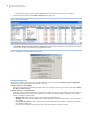
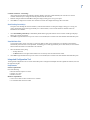
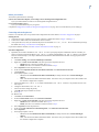
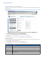
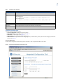
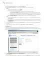
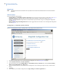
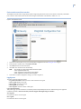
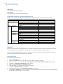
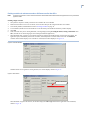
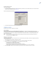
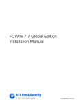
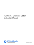
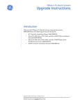
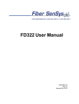
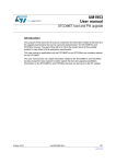
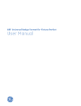
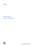
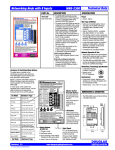
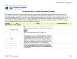
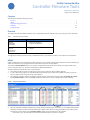
Facility Commander Wnx
Controller Firmware Tools
460614001A • March 2007
Copyright © 2007, GE Security Inc.
Contents
This document contains the following sections:
Overview . . . . . . . . . . . . . . . . . . . . . . . . . . . . . . . . . . . . . . . . . . . . . . . . . . . . . . . . . . . . . . . . . . . . . . . . . . . . . . . . . . . . . . . . . . 1
eFlash . . . . . . . . . . . . . . . . . . . . . . . . . . . . . . . . . . . . . . . . . . . . . . . . . . . . . . . . . . . . . . . . . . . . . . . . . . . . . . . . . . . . . . . . . . . . . 1
Integrated Configuration Tool . . . . . . . . . . . . . . . . . . . . . . . . . . . . . . . . . . . . . . . . . . . . . . . . . . . . . . . . . . . . . . . . . . . . . . . . . . 3
FlashTool . . . . . . . . . . . . . . . . . . . . . . . . . . . . . . . . . . . . . . . . . . . . . . . . . . . . . . . . . . . . . . . . . . . . . . . . . . . . . . . . . . . . . . . . . 18
Troubleshooting . . . . . . . . . . . . . . . . . . . . . . . . . . . . . . . . . . . . . . . . . . . . . . . . . . . . . . . . . . . . . . . . . . . . . . . . . . . . . . . . . . . . 22
Overview
This chapter describes three different firmware tools. To determine which tool would be best for your setup, refer to the chart below:
Table 1.
Controller firmware tools available
Controller
Tool available
M5PXNplus
M3000PXNplus
M2000PXNplus
• eFlash: flash capability only
• Integrated Configuration Tool
Micro/5-PXN
Micro/5-PX
Micro/PXN-2000
Micro/PX-2000
• eFlash
• FlashTool
Throughout this manual, reference to Facility CommanderTM Wnx is represented as “FCWnx” in text content to avoid repetition.
eFlash
eFlash is a flash method accessed within the FCWnx application. The procedure to flash has been integrated so that the controller stays
online and continues to process badge and alarm activity while in the process of being flashed.
The FCWnx Controller Monitor allows you to monitor communications and control each controller in the system. (Refer to the
Facility Commander Wnx User Manual or Online Help for additional information.)
To flash controllers that already have SP3.x or later firmware:
1. Verify that the FCWnx services are running (refer to the Facility Commander Wnx Installation Manual).
2. Log on to the FCWnx program. The login ID and password must belong to a member of the spadmin local user group on the
Server computer and the user group on any client computer.)
3. Verify that the controller is online in the FCWnx program. From the Application Group pane, select the Monitors & Controls,
then Controller Monitor. Check that the State column reads Online. If not, set the controller online before continuing.
Figure 1. Sample Controller Monitor
4.
Select the controller or multiple controllers that you want to flash. If flashing a line of controllers, we recommend starting with the
end-of-line controller, and work toward the head-of-line controller. This requires a working knowledge of your FCWnx system.
The firmware version column on the Controller Monitor displays the current firmware on the controller.
• If the LED is green, the controller firmware matches the latest firmware on the Server computer.
2
Facility Commander Wnx
Controller Installation Tools
5.
• If the LED is yellow, the controller firmware does not match with the latest firmware on the Server computer.
Click the right-mouse button and select Flash Controller(s) from popup menu.
Figure 2. Flash Controller (s) option
The Controller Flash & Controller Preference Configuration window displays. This window is only available if the controller
is online. There are three options. Refer to the appropriate section below.
Figure 3. Controller Flash & Controller Preference Configuration
View/Edit Parameter Info
This option is available for selection of a single controller. When this option is selected, the Controller Preference Configuration
window displays and the configuration for the controller is retrieved.
Controller Preference - Direct/Dialup:
(This option not supported for the PXNplus controller.) allows you to change the connection type of the controller and its Address,
Idle Time, and DI res tolerance.
Controller Preference - Credential Format:
displays the custom credential formats that are currently in the controller. If there are no custom formats, the fields are empty. If a
format in the database does not match what is available in the controller, the window list displays the message ‘Unrecognized
Format.’ to change the credential format:
• Magnetic stripe: Select the type of magnetic stripe format from the drop-down list.
• Wiegand: Click Assign formats to display a list of available Wiegand credential formats from which to choose and assign to
this controller.
• Clear formats in Controller: Click to clear all custom credential formats from the controller. Credentials associated with
those formats no longer work.
If you change the credential format, any format that existed in the controller previously is replaced.
3
Controller Preference - Networking:
(This option not supported for the PXNplus controller.) displays only if the system identified your controller as a network
controller and allows you to change the network preferences for the controller.
1. Make the changes needed and click OK. A dialog box displays asking you to verify your request.
2. Click OK to re-configure the controller. The controller resets after the configuration changes have been made.
Start Flashing Controller(s)
This option starts flashing the selected controller(s) with the latest firmware. A dialog box displays, asking you to verify your
request. The flashing process takes approximately two to three minutes; it varies with the amount of data that needs to be
transmitted to the controller.
1.
2.
Click Start Flashing Controller(s) to immediately download the appropriate firmware to the controller. A dialog box displays
asking you to verify your request.
Click OK to begin the flash and reset process. After a successful flash, the controller resets and a database download takes place.
View/Edit Flash Files
Use this option ONLY when it is necessary to selectively flash an older version of firmware on a controller. This application
automatically selects the latest version by default. The flashing process takes approximately two to three minutes; it varies with the
amount of data that needs to be transmitted to the controller.
1.
2.
Select the firmware file by using
• the drop-down list
• the Browse button to navigate another media source or directory where the firmware files reside.
Click OK to begin the flash and reset process. After a successful flash, the controller resets and a database download takes place.
Integrated Configuration Tool
The Integrated Configuration Tool is a browser-based utility used to configure the PXNplus CPU board, update the firmware, and view
the application log file.
Requirements
Software requirements
One of the following:
• Microsoft Internet Explorer 6.0 or later
• Netscape 7.0 or later
• Mozilla 5.0 or later
Hardware requirements
• Cat5 crossover cable for direct connection to a controller
• Cat 5 standard cable with network hub
4
Facility Commander Wnx
Controller Installation Tools
PXNplus controller connection configurations
Figure 4. Connecting directly using crossover cable
Figure 5. Connecting through network hub
5
Before you continue
Answer these questions before continuing:
Is there a firewall on the computer you are using to access the Integrated Configuration Tool?
If yes, you need to disable it in order to use the Integrated Configuration Tool.
Is your network using a proxy?
If yes, you need to disable the proxy or bypass it.
Complete the Configuration checklist for Integrated Configuration Tool on page 18 for each controller that you are setting up.
Connecting and starting the tool
If this is a new controller, there are special first-time configuration instructions. Refer to First-time configuration on page 5.
Starting the tool
1. Connect the PC to the controller using one of the connection configurations shown in Figure 4 and Figure 5.
2. In the browser Address field, enter the IP address of the controller.
3. At the password screen, enter your username and password. The default is install, install. We recommend that you change
this default. See Change Username/Password on page 14.
If you need to flash the controller, see Flash controller menu/Flash controller on page 17.
First-time configuration
1. By default, the controller’s IP address is 192.168.6.6. To have your laptop/computer communicate with the controller, you
must set your laptop/computer IP address to 192.168.6.5, or similar valid IP address (192.168.6.x where x is any number
between 1 and 254 except 6). The setup is different between Windows 2000 and Windows XP. Refer to the appropriate section.
For Windows 2000:
a. Click Start, Settings, then Network and Dial-up Connections.
b. Right-click on Local Area Connection. If the first option in the drop-down list box is:
•
Disable, then the connection is enabled. Go to step c.
•
Enable, then select it to enable the connection. Return to step a.
c. Select Properties from the drop-down list box.
d. In the section Components checked are used in this connection, select Internet Protocol TCP/IP.
e. Click Properties.
f. If this laptop/computer is set for:
•
DHCP, then the field Obtain an IP address automatically is already selected. Select Use the following IP
address.
•
Static, write down the IP address and Subnet number. You need to reset your computer back to these numbers once
the controller configuration is complete.
g. Enter the IP address 192.168.6.5, or a similar valid IP address (192.168.6.x where x is any number between 1 and
254 except 6).
h. Change the subnet mask to 255.255.255.0.
i. You do not need to change the gateway.
j. Click OK until all open windows are closed.
k. Go to step 2.
For Windows XP:
a. Click Start, then Control Panel.
b. From the Control Panel window, select Network Connections.
c. Right-click on Local Area Connection. If the first option in the drop-down list box is:
•
Disable, then the connection is enabled. Go to step d.
•
Enable, then select it to enable the connection. Return to step a.
d. Select Properties from the drop-down list.
e. In the section This connection uses the following items:, select Internet Protocol TCP/IP.
f. Select Properties.
g. If this laptop/computer is set for:
•
DHCP, then the field Obtain an IP address automatically is already selected. Select Use the following IP
address.
•
Static, write down the IP address and Subnet number. You need to reset your computer back to these numbers once
the controller configuration is complete.
6
Facility Commander Wnx
Controller Installation Tools
h.
2.
3.
4.
5.
6.
Enter the IP address 192.168.6.5, or a similar valid IP address (192.168.6.x where x is any number between 1 and
254 except 6).
i. Change the subnet to 255.255.255.0.
j. You do not need to change the gateway.
k. Click OK until all open windows are closed.
Connect the Cat-5 crossover cable from the Ethernet port on your laptop or computer directly to the controller Ethernet port (no
hub or switch).
If your controller is not yet powered up, do so now.
Open an Internet browser window on your laptop/computer.
In the browser’s Address field, enter the default static IP address of the controller: 192.168.6.6
The Integrated Configuration Tool starts. At the password screen, enter your username and password. The default is install,
install. We recommend that you change this default. See Change Username/Password on page 14.
Controller setup overview
To set up a network controller
In order to set up a network controller, you must complete these screens:
• Controller Configuration menu->Host/Connection type: Select the software package and network. See Controller
Configuration menu->Host/Connection type on page 7.
• Controller Information menu->Controller information: Set the controller address. See Controller Information
menu->Controller Information on page 8.
• Controller Parameters menu->Network configuration: The setup depends on whether the IP address is static or dynamic. See
Network configuration on page 9.
• Controller Parameters menu->Dial configuration: If using the optional dial fallback feature, you must complete the Dialup tab
also. See Dial configuration on page 10.
After completing all the screens, click Apply Changes under the Administration menu and then click Restart Application for the
changes to take effect.
To set up a dialup controller
In order to set up a dialup controller, you must complete these screens:
• Controller Configuration menu->Host/Connection type: Select the software package and network. See Controller
Configuration menu->Host/Connection type on page 7.
• Controller Information menu->Controller information: Set the controller address.See Controller Information
menu->Controller Information on page 8.
• Controller Parameters menu->Dial configuration: If using the optional dial-up (fallback) feature, you must complete the
Dialup tab also. See Dial configuration on page 10.
After completing all the screens, click Apply Changes under the Administration menu and then click Restart Application for the
changes to take effect.
To set up a direct controller
In order to set up a direct controller, you must complete these screens:
• Controller Configuration menu->Host/Connection type: Select the software package and network. See Controller
Configuration menu->Host/Connection type on page 7.
• Controller Information menu->Controller information: Set the controller address. See Controller Information
menu->Controller Information on page 8.
7
Controller Configuration menu->Host/Connection type
Use this form to select the software package and connection type.
Figure 6. Host/Configuration type screen
1.
2.
3.
4.
5.
6.
If you have not already done so, log on to the Integrated Configuration Tool. See Starting the tool on page 5.
From the Controller Configuration menu, select Host/Connection Type.
In the Host/Server Type field, select Facility Commander Wnx.
In the Primary Connection Type field, for:
• network controllers, select Ethernet.
• dialup controllers, select Dialup.
• direct controllers, select Direct.
Click Save.
If this completes your controller configuration, click Apply Changes then Restart Application now.
8
Facility Commander Wnx
Controller Installation Tools
Controller Information menu->Controller Information
Use this form to set the controller’s address. This form also provides the controller online/offline status, build and application versions,
and modem baud rate.
Figure 7. Controller Information screen
1.
2.
3.
4.
5.
From the Controller Information menu, select Controller Information.
To set the controller address, enter the number in the Controller Address field.
To use the status reports in the Other Info field, see Using the Other Info field on page 8.
Click Save.
If this completes your controller configuration, click Apply Changes then Restart Application now.
Using the Other Info field
There are several status reports based on uClinux commands which are available for checking and monitoring the PXNplus board. Call
GE Customer Support for assistance with these reports.
1. In the Other Info field, click the down arrow for a list of available reports.
2. Select the report you want. See Table 2 below for a brief explanation of each report.
Table 2.
Controller Info reports
Report
Description
Memory Usage
displays amount of memory available, both used and free
Process State
lists which processes are running
Board Info
displays hardware related information, such as boot and board version
OS Info
displays information related to the linux operating system on the controller
Uptime
time since the last reboot
DB File Info
lists persistence-related database files
9
Table 2.
Controller Info reports (continued)
Report
Description
Message Info
lists data on the controller’s message queues
Ping Host
pings the host from the controller (based on the current host IP or name)
Successful ping result:
2 packets transmitted, 2 packets received, 0% packet loss
Unsuccessful ping result:
2 packets transmitted, 0 packets received, 100% packet loss
Check Route
checks route information from the controller
Thread Status
lists the application firmware components and whether they are currently running
DMA Info
status of the DMA IO interface
Controller Parameters menu
The menu contains the following options:
• Network configuration: configure the network settings.
• Dial configuration: configure dial-up settings. See page 10.
• 3DES Keys: set data encryption. See page 11.
• Badge formats: not used with Facility Commander Wnx.
• Other Parameters: set parameters such as setting badge history and alarm history memory allocation and changing username and
password. See page 12.
Network configuration
Use this form to configure the network settings for the controller. A static or dynamic IP address can be used.
Figure 8. Controller Parameters/Network configuration screen
10
Facility Commander Wnx
Controller Installation Tools
1.
2.
From the Controller Parameters menu, select Network configuration.
In the Controller Information area, set the controller name or address. Perform one of the following:
DHCP:
• For a dynamic controller IP address, select Use DHCP.
To name the controller, perform one of the following:
•
Enter a fully qualified, unique domain name in the Controller Name field. For example:
micro.getest.ge.com
•
Select the checkbox Use MAC and the controller name is generated from the Controller MAC address. A MAC
address (media access control address) is a unique identifier attached to most forms of networking equipment. The
MAC address for your PXNplus CPU board can be found in the Controller MAC field. This option disables the
Controller Name field.
Note: Give this name or MAC address to your Network Administrator so that it can be added to the DNS database.
3.
4.
5.
Static:
• For a static controller IP address, enter the IP address of the controller given to you by your Network Administrator in the
field Controller IP.
• If using a gateway, you may accept the gateway IP generated based on the controller IP or you may enter a gateway IP address
in the Gateway field.
• If using a subnet mask, you may accept the subnet mask generated based on the controller IP or you may enter a subnet mask
in the Subnet field.
If using DNS, select the Use DNS checkbox in the Host Information area. Then, enter the DNS IP address in the DNS IP field.
Click Save.
If this completes your controller configuration, click Apply Changes then Restart Application now.
Dial configuration
Use this screen to set up the dial-up or dial fallback feature. Either the on-board modem or an external modem can be used.
Figure 9. Controller Parameters/Dial configuration screen
1.
2.
3.
From the Controller Parameters menu, select Dial configuration.
In the Host Phone # 1 field, enter the phone number for the host computer. Use the format: aaa-nnn-nnnn (For example,
561-555-5555)
If there is an additional phone number to reach the host, enter it into the field Host Phone # 2, otherwise, leave the field blank.
11
4.
5.
6.
The fields Modem Init String and Modem Deinit String require values only if you are experiencing difficulties with the optional
modem board.
Click Save.
If this completes your controller configuration, click Apply Changes then Restart Application now.
DES encryption configuration
In order to secure transmissions between the controller and the host, the data is encrypted using triple DES (Data Encryption Standard)
encryption. Use this screen to enter keys which creates an encryption pattern for transmission.
CAUTION: The host DES keys and the controller DES keys MUST match!
Figure 10. Controller Parameters/3DES keys screen
1.
2.
If you have not already done so, log on to the Integrated Configuration Tool. See Starting the tool on page 5.
Click Controller Parameters, then 3DES keys.
Keep the following in mind:
• DES keys must be exactly 16 characters.
• DES keys must be valid hexadecimal characters (0 through 9, upper or lower case letters A through F).
• No two or more DES keys can have the same value.
CAUTION: You cannot modify only one key! All must be changed or you can not save.
3.
4.
Click Save.
If this completes your controller configuration, click Apply Changes then Restart Application now.
12
Facility Commander Wnx
Controller Installation Tools
Badge format
Note:
This feature of the tool is for Picture Perfect users only! FCWnx users should use the Credential Format form located in the FCWnx
application.
Other Parameters
The form contains the following fields:
• Set Badge History vs Alarm History Memory Allocation: allocate percentage of history memory to badge history. See page 12.
• Set Resistor Tolerances: tighten the range the voltage changes before detecting a 4 state DI state change. See page 13.
• Change Username/Password: change either the username and/or the password used to log on to the Integrated Configuration
Tool. See page 14.
• Disable (Enable) Integrated Configuration Tool: select this toggle field to block or allow access to the Integrated Configuration
Tool. See page 14.
Set Badge History vs Alarm History Memory Allocation
Figure 11. Parameters/Other Parameters - Set Badge History vs Alarm History Memory Allocation screen
1.
2.
3.
4.
5.
6.
If you have not already done so, log on to the Integrated Configuration Tool. See Starting the tool on page 5.
Click Controller Parameters, then Other Parameters.
Select the checkbox next to the Set Badge History vs Alarm History Memory Allocation field. The field Percent of history
buffer to use for Badge History (0 - 100) displays.
Enter the percentage of history you would like to use for badge history. The remaining percentage of history is used for alarm
history.
Click Save.
If this completes your controller configuration, click Apply Changes then Restart Application now.
13
Set Resistor Tolerances
Figure 12. Controller Parameters/Other Parameters - Set Resistor Tolerances screen
1.
2.
3.
4.
5.
6.
If you have not already done so, log on to the Integrated Configuration Tool. See Starting the tool on page 5.
Click Controller Parameters, then Other Parameters.
Select the checkbox next to the Set Resistor Tolerances field. The following fields display:
• Res Tol # 1: Tightens the range the voltage changes before detecting a 4-state DI state change
• Res Tol # 2: Reserved
• Res Tol # 3: Reserved
Enter the resistor tolerance needed in the appropriate field.
Click Save.
If this completes your controller configuration, click Apply Changes then Restart Application now.
14
Facility Commander Wnx
Controller Installation Tools
Change Username/Password
For increased security, we recommend that you change the default username and password.
Figure 13. Controller Parameters/Other Parameters - Change Username/Password screen
1.
2.
3.
4.
5.
6.
If you have not already done so, log on to the Integrated Configuration Tool. See Starting the tool on page 5.
Click Controller Parameters, then Other Parameters.
Select the checkbox next to the Change Username/Password field. The fields New Username and New Password display.
Enter a new username and password.
Click Save.
If this completes your controller configuration, click Apply Changes then Restart Application now.
Disable or Enable Integrated Configuration Tool
Disabling the Tool
1. Successfully log on to the Integrated Configuration Tool.
2. From the Controller Parameters menu, select Other Parameters.
3. Select the option Disable Integrated Configuration Tool.
4. Selecting this option generates a dialog prompt verifying your selection. You must select OK on the prompt to disable the
Integrated Configuration Tool.
15
Figure 14. Controller Parameters/Other Parameters - Disable Integrated Configuration Tool
5.
6.
To make this selection permanent, click Save, Apply Changes, then Restart Controller.
After the controller performs a successful reboot, the Integrated Configuration Tool is permanently disabled.
Enabling the Tool
There are two options to enable the Integrated Configuration Tool: temporary and permanent. The Temporary option allows access to
the Tool until the micro resets. The Permanent option allows access until you manually disable the Tool again.
Before you begin, you MUST have physical access to the controller.
Temporary enabling
1. Verify that the controller has completed the power-up boot cycle by checking that D20 is no longer in the constant ON state.
2. On the PXNplus CPU board, jumper JP2. Verify that DS6 turns ON. Allow up to five seconds for DS6 to be turned ON. Once DS6
is ON, remove the jumper and DS6 turns OFF.
3. The Integrated Configuration Tool is now enabled until the controller reboots.
Permanent enabling
1. Complete the steps in the section Temporary enabling above then return to this section.
2. Successfully log on to the Integrated Configuration Tool.
3. Select Controller Parameters, then Other Parameters.
4. Select the option Enable Integrated Configuration Tool.
5. Selecting this option generates a dialog prompt verifying your selection. You must select OK on the prompt to enable the
Integrated Configuration Tool.
6. To make this selection permanent, click Save, Apply Changes, then Restart Controller.
7. The controller performs a system reboot automatically.
8. After the controller performs a successful reboot, the Integrated Configuration Tool is permanently enabled.
16
Facility Commander Wnx
Controller Installation Tools
Administration menu
The menu contains the following options:
• Apply Changes: applies new changes.
• Restart Application: makes changes permanent.
• Restart Controller: reboots the controller.
• Restore Factory Defaults: restores factory defaults.
Apply Changes
Click this menu item to apply any new changes made to the controller’s configuration.
Restart Application
Click this menu item to make the changes to the controller permanent.
Restart Controller
Click this menu item to shut down and restart the controller.
Restore Factory Defaults
The PXNplus board is shipped with the following default settings:
• Primary Connection Type: Ethernet
• IP Address: 192.168.6.6
• Mask: 255.255.255.0
• Gateway: 192.168.6.1
There are two methods to restoring the factory default settings: through the Integrated Configuration Tool and by the CPU board. The
table below explains when to use each method.
Restore the factory defaults by ...
Result
clicking the Defaults button in the Integrated Configuration tool
Settings are restored to factory defaults except for the network configuration.
shorting JP4 until DS3 turns on
(See Integrated Configuration Tool on page 22.)
All settings are restored to the factory defaults.
17
Flash controller menu/Flash controller
The PXNplus CPU board uses a single image capable of supporting both Picture Perfect, Secure Perfect, and Facility Commander
hosts. The file is in the format (where vvvv is the four digit version number of the firmware): PXNPvvvv.efl
Figure 15. Flash Controller screen
1.
2.
3.
4.
If you have not already done so, log on to the Integrated Configuration Tool. See Starting the tool on page 5.
From the Flash Controller menu, select Flash Controller.
Click Browse and locate the new flash file.
Click Save. The controller reboots automatically.
Note:
5.
The controller may reboot several times based on the update:
1 time = application update only
2 times = application and web server or kernel update
3 times = application, web server and kernel update
If you wish to continue configuration changes, you need to log back in.
Logging menu
The menu contains the following options:
• Log Control Parameters: select the items to track and send to the log file.
• View Log File: displays the log file.
• Save Log File: saves the log to a file.
• Print Log File: prints the log.
• Clear Log File: clears the contents of the log file.
Log Control Parameters
The system logger provides verification of controller operation independently from the host. Other filtering can be applied to
troubleshoot problems; contact GE Security Customer Support and Engineering for assistance.
View Log File
Click this menu item to view the logfile.
Save Log File
Click this menu item to save the log file.
18
Facility Commander Wnx
Controller Installation Tools
Print Log File
Click this menu item to print the log file.
Clear Log File
Click this menu item to clear the contents of the log file.
Configuration checklist for Integrated Configuration Tool
In order to complete controller configuration using the Integrated Configuration Tool, you need the following information:
Communication type
Information needed
Direct
Controller address:
Dial-up
Controller address:
Write your answer here
Phone number to reach host:
Secondary phone number to reach host:
Ethernet
Use DHCP: NO
Use DNS: NO
Controller IP:
Gateway:
Subnet:
Host IP: (Optional)
Use DHCP: YES
Use DNS: YES
Controller Name or Controller MAC which is provided for you:
Use DHCP: NO
Use DNS: YES
Controller IP:
Host Name: (Optional)
Gateway:
Subnet:
Host Name: (Optional)
Domain: (Optional)
DNS IP: (Optional)
Use DHCP: YES
Use DNS: NO
Controller Name or Controller MAC which is provided for you:
Host IP: (Optional)
FlashTool
FlashTool is a flash method for downloading firmware to controllers in maintenance mode or controllers with firmware earlier than
SP3.x. To upgrade controllers with firmware earlier than SP3.x, you MUST use the FlashTool method of flashing.
Before flashing (downloading application code to) your controllers in maintenance mode or controllers with firmware earlier than
SP3.X, you need to install the Micro Installation Tool - FlashTool.
Installing FlashTool
To install the FlashTool application:
1. Log on as local administrator.
2.
3.
4.
5.
6.
7.
8.
9.
In Windows® Explorer, navigate to the FCWnx\Firmware folder on the Server computer.
Double-click the FlashTool.EXE file. The Micro Installation Tool - FlashTool Installation Welcome window displays.
Click Next. The Select Destination Directory window displays.
Review and verify the destination of the FlashTool folder.
Verify that adequate free disk space is available for the installation.
Click Next. The Ready to Install window displays.
Click Next. Install completes and an Installation Completed window displays.
Click Finish. The FlashTool application closes and there is now a FlashTool folder in the location that you selected for installation
on your computer along with an icon on your desktop.
19
Flashing controllers in maintenance mode or SP firmware earlier than SP3.x
Note:
Controllers in maintenance mode or firmware earlier than SP3.x MUST be flashed with the FlashTool application found in your Flashtool
application folder.
Flashing a single controller
1. Verify that the computer is serially connected to the controller that is to be flashed.
2. Make sure that FCWnx services are not started, or the selected comm port has assigned controllers set to offline.
3. If not already installed, install FlashTool. Refer to Installing FlashTool on page 18.
4. To run FlashTool, double-click on the FlashTool icon on the desktop. The FlashTool introductory window displays.
5. Click OK.
6. If this is the first time you are running FlashTool, a message displays stating No config file found, creating a default file. Click
OK. (You will not see this message again when running the FlashTool application.)
7. When FlashTool loads, it prompts you to add new files that are found in the FlashTool folder. Answer Yes to all prompts. The
application opens, automatically searches for controllers, and usually finds a controller within 30 seconds. The FlashTool
controller status window displays. If no controller is connected, the window displays as in Figure 16.
Figure 16. FlashTool Window
If FlashTool does not recognize the existing firmware, the window displays similar to Figure 17.
Figure 17. Micro Status
Needs to be flashed.
When FlashTool recognizes the firmware, the window displays the Micro Type and firmware application code information,
similar to Figure 18.
20
Facility Commander Wnx
Controller Installation Tools
Figure 18. FlashTool Micro Status
8.
A controller can be flashed with application firmware in two ways:
a. Use one of the Automatic Firmware Flash buttons in the middle of the window. Click the button that corresponds to the
firmware you want. (The buttons display the latest firmware release on your computer.) The download and flash process
begins.
b. Alternatively, you may click Micro Flash from the Options listed on the left of the window. A drop-down list of firmware
displays.
•
Select the latest version of Secure Perfect x.000 App Code.
•
Click Start Flash. The download and flash process begins.
Note:
9.
If you are flashing a Micro/5-PXN, you must follow the steps in this order:
1. Flash the OS firmware.
2. Allow FlashTool to identify the controller.
3. Flash the application firmware.
Go to Download and Flash Process on page 21 for the completion of the flash process.
Flashing a Line of Controllers
FlashTool can flash all controllers in a line that have been selected and fully identified.
1. Select Search for Line of Micros. FlashTool searches for all controllers in a specified communication line. The results of the
search (up to 8 controllers) are displayed in the box below the Status field.
2. Click an individual controller from the list, then the Select button to select an individual controller from the list of controllers
found.:
CAUTION: If you choose to flash each controller individually and not the entire line of controllers, you MUST start
flashing the end-of-line controllers first, and work your way up the line. The head-of-line controller MUST be
flashed last. If you do not follow this order and start with the head-of-line, you cannot flash the downstream
controllers. The way to prevent this from occurring is to select all controllers and flash the entire line at the
same time.
-ORClick Select All to select the entire line of controllers at one time.
Note:
3.
4.
5.
6.
To flash the entire line of controllers, all controllers must be selected and identified prior to starting the flash process. The
hourglass icon reminds you to wait until the system identifies the selected controller/controllers and allows you to proceed.
Once selected and identified, an asterisk displays in front of the controller name in the list. A list box displays the firmware for
each controller. Scroll up or down in the list box to view the version information for each controller that has been selected. The
parameter block information may be obtained for a selected controller by clicking Parameters, which is enabled when a controller
is selected. (Refer to Editing the Parameter Block on page 21 and Syntax Checking on page 21.)
Click Deselect to cancel the selection of an individual controller.
Begin the flash process using one of the following methods:
• Click one of the Automatic Firmware Flash buttons.
• Click Micro Flash, select firmware from the firmware drop-down box, and then click Start Flash.
Continue to the next section.
21
Download and Flash Process
To process the download:
1. The firmware download and flash process takes approximately ten minutes for each controller flashed. You can monitor the flash
progress window that displays, similar to Figure 19.
Figure 19. Standard FlashTool Flash Window
2.
The window automatically closes after a successful flash process.
Configuring a controller
FlashTool can also be used to configure your controller.
Syntax Checking
From the File drop-down menu, Parameter Block Syntax Checking can be enabled or disabled. Parameter block syntax
checking impedes illegal combinations of settings that are controller-specific. A syntax error occurs if the program cannot understand
the command that has been entered. It is strongly recommended that this setting remain enabled. A warning message displays if you
choose to disable this feature.
Note:
When configuring a Micro/5-PXN controller that contains anything other than SP3.x firmware (for example, Secure Perfect 2.1 or
Picture Perfect), this option MUST be disabled.
Editing the Parameter Block
The controller parameter block holds controller data such as controller address, phone numbers, and network configuration parameters.
To edit the parameter block:
1. Allow sufficient time for FlashTool to identify the controller.
2. Click Parameters. FlashTool reads the parameter block in the controller and displays it in the window.
3. Edit as necessary. Select the Networking tab to enter information for a Micro/5-PXN.
• You MUST enter an IP address for the controller.
• A host IP address is not required and can be left blank.
• Enter the Gateway IP address (is the same as the controller IP address).
• All other fields are set by default. Only change them if necessary depending on your network configuration.
4. Click Save to Micro. FlashTool writes the data into the parameter block of the controller and resets the controller.
22
Facility Commander Wnx
Controller Installation Tools
Troubleshooting
eFlash
Problem: No flash files are listed in the combo boxes.
Resolution: This represents a share permissions issue. Make sure you are logged in as a user in the SPAdmin group. If not, log back in
as a user in this group.
Integrated Configuration Tool
Problem: I need to restore the factory default settings.
Resolution:
There are two methods to restoring the factory default settings: through the Integrated Configuration Tool and at the controller. The
table below explains when to use each method.
Table 3.
Restoring factory defaults
Restore the factory defaults by ...
Result
Clicking the Defaults button in the Integrated Configuration Tool
Settings are restored to factory defaults except for the network configuration.
Short JP4 (Restore Defaults pins) on the PXNplus CPU board until DS3 turns on.
All settings are restored to the factory defaults.
The controller is now offline from the host and the factory defaults have been restored. The factory defaults are as follows:
• Host Server/Type: Picture Perfect
• Primary Connection Type: Ethernet
• IP Address: 192.168.6.6
• Mask: 255.255.255.0
• Gateway: 192.168.6.1
If necessary, reconfigure the controller using the appropriate instructions found in your controller manual.
Problem: The network controller does not connect.
Resolution:
1. Verify your network settings in the Integrated Configuration Tool and in the FCWnx application:
• controller IP address and micro address
• network mask
• gateway IP
• DHCP/DNS server
2. Check the connectivity by using the ping command. Use the Ping Host option in the Integrated Configuration Tool.
a. In the Integrated Configuration Tool, select Micro Info.
b. From the Other Info drop-down list, select Ping Host.
Successful ping example:
23
Unsuccessful ping example:
Problem: The dial-up micro does not connect.
Resolution:
1. Verify your settings in the Integrated Configuration Tool and in the FCWnx application:
• micro address
• modem strings
• baud rate settings
• cabling
2. If using the PXNplus controller, verify the modem jumper setting on the CPU board:
• external modem: 1 and 2
• on-board modem: 2 and 3
3. Verify modem LED activity. Refer to your micro manual for details.
24
Facility Commander Wnx
Controller Installation Tools