1
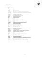
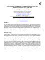
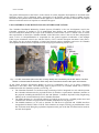
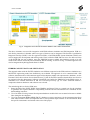
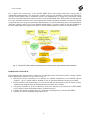
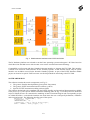
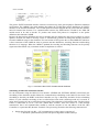
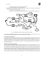
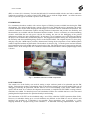
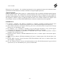
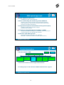
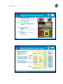
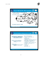
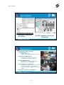
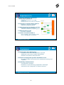
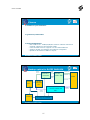
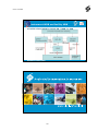
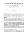
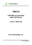
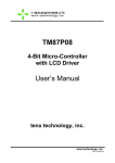
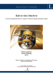
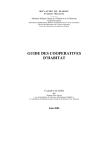
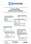
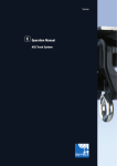
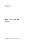
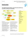
UNCLASSIFIED
Nationaal Lucht- en Ruimtevaartlaboratorium
National Aerospace Laboratory NLR
Executive summary
The EuTEF Simulator Model: a hybrid implementation for
operations training and validation
Report no.
NLR-TP-2008-488
Author(s)
E.A. Kuijpers
K.A. van Aarsen
E. Dutruel
A.J. Kramer
Z. Pronk
F. Raijmakers
Report classification
UNCLASSIFIED
Date
September 2008
Knowledge area(s)
Space
Problem area
The EuTEF Simulator Model(ESM)
is a tool for training and validation
of EuTEF operations. In order to
support the operations of the
Columbus payloads, some
Engineering Models (EM) are used
by the ground segment, mainly for
preparatory activities involving
testing, training and validation. For
one external payload, the European
Technology Exposure Facility
(EuTEF) only the central core, the
Data Handling and Power
engineering Unit(DHPU), was
available as part of the normal
development cycle. A few
instrument hardware models were
expected to become available. The
EuTEF Simulator Model (ESM)
project had the objective to
complete the basic facility
architecture with a set of
representative instrument software
models and to integrate with the
ERASMUS User Support Operation
Centre (USOC) infrastructure to
enable operational training and
validation of operational products
for EuTEF.
Descriptor(s)
Simulation
EuTEF
Telescience
USOC
Description of work
The architecture contains a generic
part including a model for data
This report is based on a presentation at the 10th International Workshop on
Simulation for European Space Programmes, Noordwijk, 7-9 October 2008.
UNCLASSIFIED
UNCLASSIFIED
The EuTEF Simulator Model: a hybrid implementation for operations
training and validation
interfacing with the EuTEF DHPU
and an instrument specific part
implemented via a higher level rulebased coding formalism. The ESM
implements all the interfaces of the
EuTEF DHPU EM. Five
instruments hardware models with
various degrees of fidelity became
available during the development.
he realism of the ESM
implementation allowed integrating
the hardware models while keeping
the advantages of software
simulation. The software simulation
of instruments replaces missing
hardware instruments and provides
the flexibility and functionalities
not available with the instrument
hardware models. Both the RS-422
and Mil-Std-1553 type instrument
interfaces have been implemented
within a EuroSim simulation
environment. Stimuli to represent
the power usage of instruments and
thermistors for EuTEF monitoring
have been implemented. For one
instrument, the Earth Viewing
Camera (EVC), the high rate bit
stream interface which is handled
by Columbus has been implemented
as a hardware adapter to connect to
the ERASMUS USOC
infrastructure.
Results and conclusions
The design and experiences using
the EuTEF Simulator Model are
described. The hybrid design
concept selected initially turned out
to be a more challenging effort than
anticipated, but reuse of the central
EuTEF DHPU EM proved to be
essential. For continued operational
use the separation between the
instrument model specifications and
the ESM core software will allow to
integrate flight experiences.
Applicability
The design will be used for training
and validation of EuTEF
operational products. ESM was
developed under ESA contract no.
13980/99/NL/PG: WO-14 realised
with Dutch national support for the
Erasmus USOC.
Nationaal Lucht- en Ruimtevaartlaboratorium, National Aerospace Laboratory NLR
UNCLASSIFIED
Anthony Fokkerweg 2, 1059 CM Amsterdam,
P.O. Box 90502, 1006 BM Amsterdam, The Netherlands
Telephone +31 20 511 31 13, Fax +31 20 511 32 10, Web site: www.nlr.nl
Nationaal Lucht- en Ruimtevaartlaboratorium
National Aerospace Laboratory NLR
NLR-TP-2008-488
The EuTEF Simulator Model: a hybrid
implementation for operations training and
validation
E.A. Kuijpers, K.A. van Aarsen1, E. Dutruel2, A.J. Kramer, Z. Pronk
and F. Raijmakers1
1
Atos Origin
2
ESA/ESTEC -TEC-SWG
This report is based on a presentation at the 10th International Workshop on Simulation for European Space
Programmes, Noordwijk, 7-9 October 2008.
The contents of this report may be cited on condition that full credit is given to NLR and the authors.
This publication has been refereed by the Advisory Committee AEROSPACE SYSTEMS & APPLICATIONS.
Customer
European Space Agency
Contract number
13980/99/NL/PG: WO-14
Owner
National Aerospace Laboratory NLR + partner(s)
Division NLR
Aerospace Systems & Applications
Distribution
Unlimited
Classification of title
Unclassified
April 2009
Approved by:
Author
Reviewer
Managing department
Nationaal Lucht- en Ruimtevaartlaboratorium
National Aerospace Laboratory NLR
NLR-TP-2008-488
Summary
For one Columbus external payload known as the European Technology Exposure Facility
(EuTEF) the central core comprising the Data Handling and Power engineering Unit (DHPU),
became available to the Erasmus USOC as an engineering model after the normal engineering
development cycle. This unit became the basis for a simulator development needed to support
the EuTEF training and operations activities. A hybrid software and hardware simulation of
instruments completes the central core to provide a simulation of the full EuTEF facility. Also,
the power and thermal conditioning was modelled in the final integrated EuTEF Simulator
Model at the Erasmus USOC.
ESM was developed under ESA contract no. 13980/99/NL/PG: WO-14 realised with Dutch
national support for the Erasmus USOC.
3
NLR-TP-2008-488
Contents
ABSTRACT
7
INTRODUCTION
7
USOC REFERENCE ARCHITECTURE AND GENERIC SIMULATORS
8
HYBRID CONCEPT PAYLOAD SIMULATION
9
HARDWARE OVERVIEW
10
SOFTWARE DESIGN
11
Scheduling Of Mil-1553 Instrument Models
12
RS-422 Instrument modelling
13
Modularity for Instrument Modelling
13
14
EXPERIENCES
EuTEF DPHU EM
14
RS-422 Instrument Implementation Experiences
15
Mil-Std-1553 Instruments Implementation Experiences
15
Use of EVC Bitstream
15
15
CONCLUSIONS AND LESSONS LEARNED
16
Acknowledgements
16
REFERENCES
Appendix A
17
Presentation handout
4
NLR-TP-2008-488
Abbreviations
BDE
Batch Data Entry
CCSDS
Consultative Committee on Space Data Systems
CD-MCS
Columbus Distributed Monitoring and Control System
Col-CC
Columbus Control Centre
DHPU
Data handling and Power Unit
EDR
European Drawer rack
EM
Engineering Model
EPSS
EDR-PCDF System Simulator
ESA
European Space Agency
ESM
EuTEF Simulator Model
EuTEF
European technology Exposure Facility
EVC
Earth Viewing Camera
FIPEX
Flux-Probe Experiment
FRC
Facility responsible centre
HRDL
High Rate Data Link
HRDP
High Rate Data Processor
MDB
Mission Data Base
MEDET
Materials Exposure and Degradation Experiment
PaCTS
Payload Computer Test System
PCDF
Protein Crystallisation Diagnostic Facility
PI
Principal Investigator
PLEGPAY
Plasma Electronic Gun Payload
STD
State Transition Diagram
TAXI
Transparent Asynchronous Transmit/Receive Interface
USOC
User Support Operations Centre
YAMCS
Yet Another Monitoring and Control System
5
NLR-TP-2008-488
THE EUTEF SIMULATOR MODEL: A HYBRID IMPLEMENTATION FOR
OPERATIONS TRAINING AND VALIDATION
E.A. Kuijpers (1), K.A. van Aarsen(2), E.Dutruel(3),
A.Kramer(1), Z.Pronk(1), F.Raijmakers(2)
(1)
National Aerospace Laboratory NLR, Space department
P.O.Box 153, 8300 AD Emmeloord, the Netherlands
E-mail: [email protected], [email protected], [email protected]
(2)
Atos Origin
Papendorpseweg 93, 3528 BJ Utrecht
E-mail: [email protected], [email protected]
(3)
ESA/ESTEC -TEC-SWG
P.O.Box 2999, 2200AG Noordwijk , the Netherlands
E-mail: [email protected]
ABSTRACT
For one Columbus external payload known as the European Technology Exposure Facility (EuTEF) the
central core comprising the Data Handling and Power engineering Unit (DHPU), became available to the
Erasmus USOC as an engineering model after the normal engineering development cycle. This unit became
the basis for a simulator development needed to support the EuTEF training and operations activities. A
hybrid software and hardware simulation of instruments completes the central core to provide a simulation of
the full EuTEF facility. Also, the power and thermal conditioning was modelled in the final integrated
EuTEF Simulator Model at the Erasmus USOC.
INTRODUCTION
In order to support the flight operations of the Columbus payloads, Engineering Models (EM) are used by
the Columbus ground segment, mainly for preparatory activities involving testing, training and validation.
User Support and Operations Centres (USOCs) have a dedicated responsibility to operate the Columbus
payload facilities. The data monitoring and control system used at the USOC is composed partly of generic
equipment available to all User Support and Operation Centres and partly of payload specific equipment
which includes engineering models resembling the flight configuration of the payloads, the Flight
Model(FM), allocated to a given USOC.
The Erasmus USOC was assigned responsibility for the European Drawer Rack (EDR) and the European
Technology Exposure Facility (EuTEF) [1]. Both consist of a platform on which several individual
instruments can be integrated. The EuTEF facility integrates a suite of nine instruments covering a wide
range of technology and science research objectives (see Fig. 1). The EuTEF facility is attached externally to
the Columbus model of the ISS and is operational since the launch at the beginning of 2008. The EuTEF
Simulator Model (ESM) project had the objective to complete the basic hardware facility architecture with a
set of representative instrument software models and to integrate all systems with the Erasmus USOC at
ESTEC to enable operational training and validation of operational products for EuTEF. This paper describes
the hybrid implementation used for the ESM development.
6
NLR-TP-2008-488
The generic infrastructure at the USOCs in the context of various simulator developments is described in the
following section. This is followed with a description of the EuTEF specific models available and the
rationale for the hybrid EuTEF Simulator Model approach. A hardware and software architecture description
followed with a discussion of experiences concludes the paper.
USOC REFERENCE ARCHITECTURE AND GENERIC SIMULATORS
The Columbus Distributed Monitoring Control System (CD-MCS) is the core development used in the
Columbus operations. It includes a set of standardized data displays and commanding tools. The Data
Services Subsystem (DaSS) in the scope of the Columbus Control Centre (Col-CC) allows users to control
their experiments on board the Columbus Module of the ISS and to retrieve data in real-time and playback
mode. Col-CC in Oberpfaffenhofen is responsible for the ground segment coordination of the multiple
USOC inputs. Simulators exist for use with the USOCs, Col-CC and the European Astronaut Centre (EAC).
The fidelity for the payload modelling is limited and general purpose simulation and reuse of Columbus
development facilities has been emphasised in the design [2] not allowing USOC reuse.
Fig. 1. EuTEF instruments (FM on the left, courtesy NASA) are controlled by the EuTEF DHPU. The EVC
camera is oriented towards the earth, while many other instruments measure the space environment.
At the USOC premises Engineering Models are used in combination with a set of generic simulators
dedicated to the USOC tasks. The following general purpose tools are available which can be used in
combination with all Columbus payloads (see left Fig. 2):
• The Columbus Emulator is a hardware setup consisting of 4 PCs integrated in a rack which represent
the Columbus infrastructure for payload facilities. It includes a representative hardware interface to
the payloads including the Mil-Std-1553 bus and Ethernet. Columbus Payload Facility Engineering
Models can be connected directly to the Columbus Emulator.
• The SESS simulator is a Java based software tool which can be used as a CCSDS packet router and
contains basic facilities for payload and Columbus simulation for test purposes.
• The MARS simulator is a PC tool to simulate TC/TM flow for payloads and CCSDS interfaces
encapsulated in DaSS, UDP or TCP/IP. This simulator can import a facility payload database in the
PaCTS format used during the payload development and is part of the PaCTS related toolset used for
test and development.
7
NLR-TP-2008-488
Fig. 2. Integration of the EuTEF Simulator Model in the USOC infrastructure.
The above elements were used for integration with EDR software simulation and EM integration. EDR is a
rack facility internal to Columbus where two types of drawers can be integrated. The Protein Crystallisation
Diagnostic Facility (PCDF) is the first payload for EDR. A full EDR PCDF System Simulator (EPSS) was
used to support the development and training at the USOC while the EDR EM was in use for other activities
or the PCDF-EM was not available. Once the EDR-EM became available the simulator proved to be still
useful in the context of fault-injection simulation and for training. As shown in Fig. 2 a similar approach was
used to integrate the hybrid approach taken for ESM.
HYBRID CONCEPT PAYLOAD SIMULATION
The approach taken with the EuTEF simulation was different compared to the EDR software simulation as a
full EuTEF engineering model was definitively not available. The approach is to be contrasted with a full
software simulation and a full instrument payload development model with representative hardware. At the
Erasmus USOC this was done for one demo drawer [3], but for EuTEF a hardware based effort was felt to be
too expensive for nine instruments. Software simulation was feasible for EDR/PCDF in the EPSS project. A
simulation of a LIDAR instrument on ISS was exercised previously [4]. To ensure sufficient realism a
compromise between hardware and software was selected.
The main design drivers for the ESM were:
1. Reuse the EM of the EuTEF DHPU (Data Handling and Power Unit) as a central core for the simulator
to guarantee the required hardware compatibility with the RS-422 and Mil-Std-1553 standards for the
data handling interfaces.
2. Use of an Earth Viewing Camera Development hardware model which was assumed to become available
later during the development.
3. Use of an instrument MDB(i-MDB) TM/TC database to ensure consistency for the instrument interfaces
with other Erasmus USOC developments and to reuse potential improvements as the information about
the specific instruments was limited at the start of the project.
8
NLR-TP-2008-488
Fig. 3 depicts the central place of the EuTEF DHPU EM in the hybrid architecture concept and its
conditioning and monitoring. The architecture contains a generic part including a model for data interfacing
with the EuTEF DHPU and an instrument specific part implemented via a high level rule-based coding
formalism. The ESM implements all the interfaces of the EuTEF DHPU EM. Both the RS-422 and Mil-Std1553 type instrument interfaces have been implemented within a EuroSim simulation environment. Stimuli
to represent the power usage of instruments and thermistors for EuTEF monitoring have been implemented.
The Earth Viewing Camera (EVC) Development Model (DM) is a realistic model for the data handling for
the EVC Flight Model as integrated in EuTEF for which realistic hardware interfaces would be needed.
Fig. 3. The EuTEF DHPU EM is conditioned and monitored with representative data interfaces.
HARDWARE OVERVIEW
In the following the main hardware components are described where all interfaces had to comply with the
EuTEF DHPU EM connectors (J1 up to J16, see Fig. 4):
• Mil-Std-1553 board connecting to J12 allowing for Mil-bus instruments to be simulated with the
addresses 1 up to 5 which could be disabled in case an instrument hardware model was available.
• RS-422 interface board connecting to J11 for the four RS-422 instruments in EuTEF which could be
simulated and disabled when the instrument hardware model was available.
• A digital I/O module for power-on detection (J2 and J3) allowed to synchronise the EuTEF DHPU
power outlets with the instrument software simulation start-up.
• A digital I/O module for digital line (J16) detection controlling relays via the EuTEF DHPU
• Interface to resistors simulating temperatures (J15).
9
NLR-TP-2008-488
Fig. 4. ESM hardware interfaces with EuTEF DHPU EM.
The PC hardware platform was selected to run the Linux operating systems and support 3 PCI slots based on
a Dell Precision 390 Mini-tower with an Intel® CoreTM 2 Duo® Processor Dual Core Technology.
Compatibility was foreseen with the Columbus bitstream interface to integrate the EVC DM. This interface
is based on an electrical TAXI interface for the external payloads. At the Erasmus USOC only an optical
interface was available as used for the internal Columbus payloads. As part of the EuTEF Simulator Model
project an electrical to optical TAXI converter was developed built for interfacing to the EVC DM.
SOFTWARE DESIGN
The software contains three main components (see Fig. 5):
• The generic EuroSim based platform (green/yellow line pattern)
• The generic EuTEF instrument interface software (yellow)
• Specific EUTEF instrument modeling software (blue)
The software design had to be compliant with the EuTEF interface and operational documentation available
to the project [5-7]. The specific EuTEF instrument modeling (Blue in Fig. 5) is mainly based on dedicated
scripts in which the user can customize the modeling in State Transition Diagram (the corresponding scripts
are called STD-files). A rule-based formalism was used where the user could specify definitions, conditions
and event and actions. The following describes part of the syntax:
definitions = 'DEFINITIONS:’, '\n’,
c_definitions, '\n’
'ENDDEFINITIONS’, '\n’ ;
c_definitions = <any C code in global scope> ;
event = 'EVENT:’, event_trigger, '\n’,
10
NLR-TP-2008-488
[ 'CONDITIONS:’, conditions, '\n’, ]
[ 'RESPONSE:’, response_statement, '\n’, ]
[ 'COMMENT:’, quoted_string, '\n’, ]
'ACTIONS:’, '\n’,
c_statements,
'ENDACTIONS’, '\n’ ;
The generic EuTEF instrument interface software is build on top of the general purpose EuroSim simulation
environment. The i-MDB is the main database describing the CCSDS data packets definitions for TM/TC
interface to the EuTEF Instruments. The CCSDS packets could be mapped directly on the RS-422 and MilStd-1553 internal bus formats. For communication between the ESM and the CD-MCS, the ESM SW
module needs to be able to decode TC packets and encode TM packets in compliance to the packet
definitions described the i-MDB.
Because the data packets definitions are large in number and size and because they may be subject to version
updates, decision was taken to develop a tool to automatically generate encoding and decoding functions
from the i-MDB for usage in the simulator. This tool written in Perl, parses the so-called BDE files which are
a direct extraction of the i-MDB in order to generate structure definitions, encoding functions and decoding
functions in C language. When the i-MDB is updated the encoding and decoding functions can be quickly
regenerated after which only a simulator model recompilation is needed.
Fig. 5. Overview of the EuTEF Simulator Model Software.
Scheduling Of Mil-1553 Instrument Models
For the instruments using the Mil-1553 bus interface (TRIBOLAB, EUTEMP, MEDET, PLEGPAY) the
scheduling of the simulator models follows the communication scheduling on the Mil-1553 bus itself. This
scheduling is forced by the DHPU as the Bus Controller (see Fig. 6). Basically, the Mil-1553 bus scheduling
follows a cyclic schedule consisting of one so-called major frame with a duration/period of 10 seconds. A
major frame consists of 100 so-called Processing frames with a duration of 100 milliseconds. The Processing
Frame is subdivided in (16*8=) 128 slots (called Basic Frames). Each slot relates to a Mil message
transmission, that is all communication needed to send the contents of one sub address of the BC (Bus
Controller) or a particular RT (Remote Terminal). The processing Frame has the following characteristics:
•
During the first half only BC -> RT communication is taking place consisting of:
o A broadcast synchronization packet with processing frame number (always)
11
NLR-TP-2008-488
•
o A broadcast time packet (every 10th processing frame)
o One Telecommand to any instrument (optional)
During the second half only RT -> BC communication is taking place consisting of following TM
data all from one and the same instrument:
o Health data, House Keeping data, Science data
o Instrument Command Response on the Telecommand for first half of the Processing Frame.
o
IM specif. TC
IM TC MMI
TC route
Operator
IM TC
TC Data
RT #
TC in Mil packet
Mil Rx buffer
DHPU
EuroSim
Scheduler
events
STD
modeling
General TC
Read /
decode TC
Data (encoded)
RT #
SA #
Get TC
IM TM + Command
Response
Generic TC
handling
Synchronize
Send TM
IM TM MMI
Mil routing
TM in Mil packet
Mil Tx buffer
TM Data (encoded)
Model ID
type
TM Data (encoded)
RT #
SA #
TM encode
Fault
IM send TM
TM Data
Model ID
type
.
Fault
Injection MMI
Fig. 6. Scheduling of Mil-bus instruments and data flow in ESM.
The data rate for the Housekeeping packets is 0.1 Hz, 1 Hz for the Science packets and a health status rate of
1 Hz. The EuTEF DHPU EM controls the rates and the simulator has to comply.
RS-422 Instrument Modelling
For the RS-422 instruments the interface specifications of the EuTEF DHPU EM and instruments were used
to implement a generic model in which specific deviations for the individual instruments were added. For
the RS-422 instruments the refresh rate when selecting continuous mode can range from 0.1 Hz to 1
packet/hour. Therefore, the user has to request explicitly for one shot science or housekeeping telemetry for
the RS-422 instruments (one_shot_HK and one_shot_SC). The health information becomes available at a
low frequency (0.1Hz).
Modularity for Instrument Modelling
The level of detail is limited to the scope of the ESM requirements and can be easily expanded via de STDfiles representing each instrument. Due to limited information about the as-built instrument behaviour, it was
felt a rule like formalism could be the basis for improvements later. In a first iteration a subset of commands
which could be executed with the flight model on ground was the basis. Based on those experiences an
attempt was made to enhance realism via dedicated coding in the action part of the STD-rules. For each
instrument a dedicated timer variable is available in the STD-files which was incremented every second. The
user can use this to mimic events with some delays and transient behaviour. Note that the response for each
instrument depends on the interfacing method commanded via the EuTEF DHPU EM for housekeeping
12
NLR-TP-2008-488
(HK) or science (SC) telemetry. For both the Mil-Std-1553 standard and RS-422 the user had to enable the
continuous acquisition via control of the EuTEF DHPU just as with the Flight Model. An effort has been
made to represent typical command responses in the simulator.
EXPERIENCES
Five instruments hardware models with various degrees of fidelity became available later during the ESM
development. The initial hybrid design concept selected for the ESM allowed us integrating the newly
available hardware models while keeping the advantages of a flexible software simulation environment. The
software simulation of instruments replaces missing hardware instruments and provides the flexibility and
functionalities not available with the instrument hardware models. To have a telemetry en telecommanding
resource with ESM did not only prove relevant for training, but also for the debugging of the ground
infrastructure which was quite complicated [8]. In retrospect a lot of simulators were used before and during
the project, but somehow they all had their purpose. The integration and data routing was straightforward for
the telemetry and telecommanding being routed via the EuTEF DHPU. The original objective to have plugand-play using the i-MDB import could be demonstrated. During the development several i-MDB updates
could be imported without any difficulties. The hardware is shown in Fig. 7 with the power load and thermal
load simulation on the left-middle and the control on the right. The TAXI-convertor is integrated on the leftbottom corner. In the background the Columbus Emulator and EuTEF DHPU related equipment(upper half)
is shown.
Fig. 7. Hardware overview of ESM components.
EuTEF DPHU EM
The central core of the facility was used for testing a major software patch to be uploaded onto the FM
facility. Following the update a reformatting of the on-board mass memory proved to be needed. This type of
debugging could only be performed with the EM. In view of unavailability of the EuTEF DHPU EM for
repairs and the need for a software development environment, a simplified EuTEF DHPU routing software
simulation was added. For detailed power load simulation facilities are available but have to be fine-tuned
pending detailed requirements for operational analysis and training.
The instruments in EuTEF can be scheduled using a set of files called the EuTEF Operations Plan (EOP).
However, for schedules lasting up to a week validation was difficult. As the ESM is a mix of software and
hardware just speeding up a simulation is not possible. Three approaches were considered: A. a time
stepping method; B. a preprocessing of the schedule; C. A dedicated checking implementation. Option A
13
NLR-TP-2008-488
could not be implemented in view of limitations of the EuTEF DHPU EM/Columbus Emulator time
interface. Option B required pre-processing of an operational product which is not attractive. For option C a
dedicated tool was developed by Space Applications Services, Belgium, as partner in the Erasmus USOC
which proved to be sufficient, but for debugging the ESM set-up was needed.
RS-422 Instrument Implementation Experiences
Using the STD formalism the RS-422 instruments were modelled with realism depending on the instrument
hardware models which became available during the project. A DEBIE2 Engineering Model (EM) is
available with one sensor. The software supports all three sensors as in the FM. With the software model it is
possible to exercise commands and verify related error handling for bit parity checks. Using a hardware
switch, selection is possible between the software model and the EM hardware. For the purpose of testing
DEBIE-2 science telemetry processing, an option has been included to simulate large science packets. In the
DEBIE2 user interface artificial packets are generated when increasing the packet size. The number of
packets sent after a single shot science packet acquisition can also be specified. For DOSTEL an EM is
available and only a few commands are implemented. For EXPOSE instrument a limited data handling
hardware model is available to connect to the DHPU EM. All commands are also implemented in the
software model. This includes a model which is more dynamic for opening and closing the shutter. For
FIPEX there is no hardware model available to connect to the DHPU EM. The corresponding software
model is focussing on the power on/off for the various subsystems which could not be exercised for the flight
model on ground. The FIPEX resources are modelled similar to the flight model.
Mil-Std-1553 Instruments Implementation Experiences
Using the STD formalism the Mil-Std-1553 instruments were modelled. In view of a EuTEMP EM available,
the scope for the software modelled was limited. By default the use of the Mil-Std-1553 address for
EuTEMP is disabled to avoid address conflicts with the EuTEMP EM connected by default. For MEDET
and PLEGPAY there is no hardware model available to connect to the DHPU EM. Therefore, software
simulation is needed. The software model for MEDET is focusing on the power on/off for the various
subsystems and on the option to inhibit the functionality of subsystems. The software model for PLEGPAY
is focusing on the power on/off for the various experiment scenarios. For TRIBOLAB there is no hardware
model available and the software simulation is was focusing on the correct transition between states and
error handling and proved sufficient for checking of operational procedures.
Use of EVC Bitstream
As part of the ESM development a dedicated TAXI converter has been provided to exercise operations
including the bit stream data transfer which proved very useful and essential for allowing debugging in
preparation of flight operations. The power load is modelled in a dedicated EVC.std file as the development
model had an independent power source. The compatibility with the bitstream of the Flight Model could be
exploited in developing the tools required for image display and storage. Originally a software interface via
the EVC EGSE was also considered, but in retrospect a real hardware instead of software simulation proved
to be more efficient for operations preparation.
CONCLUSIONS AND LESSONS LEARNED
During the initial phase of the EuTEF flight operations the ESM simulator proved to be a valuable tool
supporting the Erasmus USOC operators in essential tasks such as debugging unexpected problems arising
on the EuTEF flight model and supporting the training program for new operators. More instrument
engineering models became available during the project than originally foreseen and could be easily
integrated due to the realism of data handling interfaces implemented. However, the software simulation
remained used for fault-injection and analyses not possible with EMs. The hybrid design concept selected
initially turned out to be a more challenging effort than anticipated, but reuse of the central EuTEF DHPU
14
NLR-TP-2008-488
EM proved to be essential. For continued operational use the separation between the instrument model
specifications and the ESM core software will allow to integrate flight experiences.
Acknowledgements
ESM was developed under ESA contract no. 13980/99/NL/PG: WO-14 realised with Dutch national support
for the Erasmus USOC. The contributions of Hans Kolkman and Tijmen Vroegop from Atos Origin are
gratefully acknowledged for the software development. The hardware support at NLR was indispensable for
the integration. Software support at NLR provided the detail for the models. Without the support Carlo
Gavazzi Space for the use of the EuTEF DHPU EM, the realisation would not have been possible.
REFERENCES
[1] Z. Pronk, L. Steinicke, J.M. Wislez, P. Dujardin, J.C. Degavre, Columbus payload operations from
remote decentralized user support and operations centres, IAF conference paper, IAC-08-A2.5.4.
[2] Chris Gilbert and Wim van Leeuwen, Reducing The Cost of Ground Systems & Operations Through
Software Re-Use, RCSGSO-5, 2003.
[3] E.A. Kuijpers , A.A. Casteleijn, V. Koehne, Using the ESA Demo Payload to verify ground support
equipment for the European Drawer Rack, EGSE Workshop, ESTEC, 17-10-2006.
[4] S. Veldman, H. Knobbout, A. Stoffelen, G.J. Marseille, and J. Fuchs, LIDAR Performance Analysis
Simulator LIPAS, IAF-99-U.3.02.
[5] EuTEF Operations Manual, TEF-MA-20000-003-CGS, issue 3, Contract report Carlo Gavazzi Space,
March 2007.
[6] DHPU-SW User Manual, TEF-MA-21200-001-CGS, issue 3, Contract report Carlo Gavazzi Space, Jan.
2007.
[7] EUTEF DHPU Interface Control Document, TEF-ICD-21200-001-CGS, issue 2, Contract report Carlo
Gavazzi Space, 1 April 2004.
[8] W. van Leeuwen, Security concepts and implementation on the ESA ISS Exploitation Program Ground
infrastructure for the ESA Human space projects, DASIA 2007.
15
NLR-TP-2008-488
This page is intentionally left blank.
16
NLR-TP-2008-488
Appendix A
Presentation handout
17
NLR-TP-2008-488
THE EUTEF SIMULATOR MODEL: A HYBRID
IMPLEMENTATION FOR OPERATIONS
TRAINING AND VALIDATION
SESP 2008 presentation
E.A. Kuijpers (1), K.A. van Aarsen(2),E.Dutruel(3)
A.Kramer(1), Z.Pronk(1), F.Raijmakers(2)
(1)National
Aerospace Laboratory NLR, Space department
Origin
(3)ESA/ESTEC -TEC-SWG
(2)Atos
Nationaal Lucht- en Ruimtevaartlaboratorium – National Aerospace Laboratory NLR
Overview
z Simulation Payload Utilisation Columbus
– European Technology Exposure Facility (EuTEF) Simulation
– Simulation at User Support and Operation Centre(USOC)
– Integration tools in infrastructure
z EuTEF Simulator Model
– EuTEF Data Handling Power Unit (DHPU) central core
– EuTEF hybrid approach
– Project description
z Software and Hardware Design
– Stimuli and monitoring hardware
– Software design
z Experiences and conclusions
2
18
NLR-TP-2008-488
EuTEF Simulation
z EuTEF external facility in orbit on Columbus with nine
instruments (technology experiments) co-ordinated via EuTEF
Data Handing Power Unit(DHPU)
z Engineering Model essential for validation while Flight Model
in orbit and for EuTEF only EuTEF DHPU EM available
3
Simulation at Erasmus USOC
z Erasmus User Support Operation Centre (USOC) at ESTEC
responsible for training and validation operations
– European Drawer Rack (EDR) – internal Columbus Facility
– European Technology Exposure Facility (EuTEF)
z Environment at USOC for operations
– Columbus Distributed Monitoring Control System (CD-MCS)
– Standardisation and integration with other ground segment
centres
z Simulator objective for training and validation USOC
– Preparation and operator training
– Validation of operational products (procedures, timelines)
z Simulation used for testing local systems and configuration
databases
z Generic tools (ESA provided) and payload specific tools(USOC)
4
19
NLR-TP-2008-488
Generic simulation tools
z DaSS simulation
Payload
(PaCTS)
– Data Services SubSystem - DaSS
– Simulation interface to Columbus Centre
and up-/downlink developed by SESS/ColCC
z Columbus Simulator
– Java based simulation tool developed by
SESS Germany
z Columbus Emulator
– Interface to EM and Columbus (Astrium)
z PaCTS
– Toolset including “Microgravity Advanced
Research and Support Centre simulator”
TM
Columbus
I/F
Columbus
DaSS
Comms
TC
z Local simulation only
– EAC, Col-CC, NASA tools not included
CD-MCS
5
EuTEF DHPU EM central core
z EuTEF DHPU EM central core
z Columbus external and instrument internal interfaces
6
20
NLR-TP-2008-488
ESM hybrid approach
z EuTEF DHPU EM central core
– Available as part of development
z Mimic conditioning and monitoring EuTEF DHPU EM
– Stimuli: power load, thermal environment(thermistors)
– Data handling to instruments: RS-422 and Mil-Std-1553
– External Columbus interfacing
z Integrate development model Earth Viewing Camera(EVC)
– Realistic model TAXI interface images
– Mil-Std-1553 interface
z Interface to instrument Mission DataBase (i-MDB)
– Instrument MDB knowledge not available at start of project
– Central reference for operational products
z Difference with EDR approach
– EDR-PCDF System Simulator (all software)
– EDR EM + instrument drawer models (all hardware)
7
Project description
z Workbreakdown
ESM
NLR
Atos
EuTEF Simulator Work breakdown
WP 1000
Requirements
WP 2000
Simulator
Design
WP 3000
Generic
Software
WP 4000
WP 5000
System
Acceptance
Integration
Testing
+ instruments
WP 6000
Management
z NLR main contractor, Atos Orgin subcontractor
z Funding as part of the Erasmus USOC infrastructure support
8
21
NLR-TP-2008-488
Integration in USOC infrastructure
Generic infrastructure with EDR simulation
EuTEF Simulator Model
EDR EM or
RS-422 inst.
HW models
EVC camera
EDR-PCDF System Simulation
EVC HRDP
Interface
HRDP
EVC Dev.
Model
Mil-Std-553
inst. HW models
Comms +
CD-MCS
Col Sim
USOC
Operator
COL-EM
(2nd)
EuTEF Instr
I/F HW
DHPU
EuTEF-EM
ESM
Core
EuTEF Instr.
COL-EM
PaCTS
(2nd)
EuTEF-EM
EGSE
EVC model
EGSE
Model SW
Simulator
platform
(Test) Operator
UHB
PI
Simulator Operator
Erasmus USOC
subsystems
EDR EM
.+ software sim.
Instrument
HW
EuTEF EM
EUTEF simulator
Developments
9
Conditioning and monitoring
z Mil-Std-1553
instrument i/f
z RS-422
instrument i/f
z A digital I/O
module for
power-on
z Digital line
detection
z Interface to
resistors
simulating
temperatures
10
22
NLR-TP-2008-488
Integration interfacing hardware
z Earth Viewing Camera
Bitstream
TAXI conversion
– Hardware interface to convert
electrical to optical TAXI for
USOC interfacing
z Power on detection
Thermal
– Instruments started based on
powering on of DHPU 28 V
outlets
Power-on
z Thermal simulation
– Manual
– Software control via relay board
option
Power load
z Power load
– Simulator control 4 loads
– RS-232 I/F
– Manual subset
Manual
ESM
controlled
11
Software ESM Workstation design
z The generic EuroSim
based platform
(green/yellow line
pattern)
z The generic EuTEF
instrument interface
software (yellow)
z Specific EUTEF
instrument modeling
software (blue)
12
23
NLR-TP-2008-488
Generic SW Mil-STD-1553 simulation
z Realistic responses to EuTEF DHPU EM
request messages
IM specif. TC
IM TC MMI
TC route
z 0.1 Hz HK, 1 Hz SC, 1Hz health
Operator
IM TC
TC Data
RT #
STD
modeling
TC in Mil packet
Mil Rx buffer
DHPU
EuroSim
Scheduler
events
General TC
Read /
decodeTC
Data (encoded)
RT #
SA #
Get TC
IM TM + Command
Response
GenericTC
handling
Synchronize
Send TM
IM TM MMI
Mil routing
TM in Mil packet
Mil Tx buffer
TM Data (encoded)
RT #
SA #
TM Data (encoded)
Model ID
type
Fault
IM send TM
TM encode
TM Data
Model ID
type
z Command response < 80ms
Fault
InjectionMMI
13
Payload Models using generic scripts
z Perl Script for i-MDB import
and generation of C-functions
– Input extracted from CDMCS operations interface
PART OF SYNTAX STD-files
definitions = 'DEFINITIONS:’, '\n’,
c_definitions, '\n’
'ENDDEFINITIONS’, '\n’ ;
c_definitions = <any C code in global scope> ;
z State Transition Diagram
– EVENTS, CONDITIONS,
ACTIONS
event = 'EVENT:’, event_trigger, '\n’,
[ 'CONDITIONS:’, conditions, '\n’, ]
[ 'RESPONSE:’, response_statement, '\n’, ]
[ 'COMMENT:’, quoted_string, '\n’, ]
z PERL script
– STD conversion to C-code for
integration with EuroSim
models
'ACTIONS:’, '\n’,
c_statements,
'ENDACTIONS’, '\n’ ;
14
24
NLR-TP-2008-488
User interfaces
Simulator interface
(EuroSim)
EuTEF Operator interface
(CD-MCS)
15
Experiences (1)
z Integration with on-going
developments
– Phased approach
– Training and familiarisation in parallel
z Instrument MDB import
– Performed several times during
development for new updates
z EuTEF DHPU EM use
– Essential for on-board debugging
– Dependency on availability
z Real-time vs non real-time
– Timelined operations involved separate
development Space Applications
Services, Belgium, partner in Erasmus
USOC
z Change to 24-hours operations
– ESM use for new operators
16
25
NLR-TP-2008-488
Experiences (2)
z Options to integrate experiences
during flight operations
– Reuse FM experience via i-MDB
validation
– During operations limited development
z Integration of Earth Viewing Camera
– Hardware references essential
– Software simulation backup
z Additional instrument Models available
– Compatility allowed integration
– Software simulation for fault-injection
z TRIBOLAB state model
– Procedure validation
z Software simulation DEBIE-2
– Mix of software and hardware model
use for debugging of interfaces
17
Conclusions
z Hybrid approach challenging
– Realism EuTEF DHPU EM hardware required
– Additional instrument models appreciated
– Software simulation essential tools
z Generic and payload specific simulation tools
– All used in USOC environment for operations training and
validation
z Flexibility demonstrated
– Configuration changes
– Resolution of issues during preparation and flight
operations with integration of lessons learned
18
26
NLR-TP-2008-488
Closure
z Thanks for your attention
z Questions/comments?
z Acknowledgements
– ESA contract no. 13980/99/NL/PG: WO-14 realised with Dutch
national support for the Erasmus USOC
– Carlo Gavazzi Team for support use of EuTEF DHPU EM
– Support at NLR on hardware and software integration
– Operators at Erasmus USOC for inputs
19
Backup option for EuTEF DHPU EM
TCP/IP
ethernet
mil-std-1553
mil-std
-1553
Columbus
I/F emulator
UDP
ethernet
EuTEF
DHPU EM
RS-422
ESM
Stim./Mon.
DASS
sim
SESS
Columbus
sim
TCP/IP
ethernet
CD-MCS
Columbus TM/TC routing
+ EuTEF DHPU SW
SIM
TCP/IP
ethernet
Routing via YAMCS
20
27
NLR-TP-2008-488
instrument-MDB and facility MDB
z PaCTS related MDB for DHPU EM, i-MDB for ESM
21
22
28