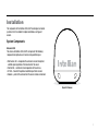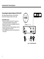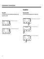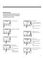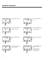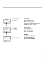
1
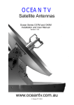
i3/i3L/i4/i4P
Installation and operation
User Manual
Document Number: 2012EF-UM1004-V1_0
Intellian Satellite TV Antenna Systems
Intellian i3/i3L/i4/i4P Serial Number
This serial number will be requested for all troubleshooting or service Inquiries.
Notice
All Right Reserved
Intellian i3/i3L/i4/i4P® and Intellian® are the registered trademarks of Intellian Technologies, Inc., and should not be appropriated without permission by Intellian Technologies,
Inc., and the information contained in this manual is the property of Intellian Technologies, Inc. Any and all parts of this manual shall not be reproduced and distributed in any form
without written prior consent by Intellian Technologies, Inc. The information contained in this manual shall be subject to change at any time without notice due to the functional
upgrade of the product.
2
Table of Contents
INTRODUCTION
INTRODUCTION TO INTELLIAN i3/i3L/i4/i4P
FEATURES OF INTELLIAN i3/i3L/i4/i4P
BASIC SYSTEM CONFIGURATION OF INTELLIAN i3/i3L/i4/i4P
4
4
5
6
INSTALLATION
SYSTEM COMPONENTS
TOOLS REQUIRED FOR INSTALLATION
PLANNING THE INSTALLATION
INSTALLATION AND MOUNTING OF ANTENNA
7
7
10
11
13
INSTALLING THE ACU
ACU DIMENSIONS
SELECTING ACU INSTALLATION SITE
CONNECTING THE SYSTEM CABLES
CONNECTING THE SYSTEM TO A GPS
ADJUSTING THE LNB SKEW ANGLE (LINEAR POLARIZATION ONLY)
18
18
19
20
23
24
OPERATION INSTRUCTION
INTRODUCTION
26
26
OPERATING THE ACU
ACU SOFT KEYS
NORMAL MODE
SETUP MODE
27
27
27
30
OPERATION USING PC CONTROLLER PROGRAM
INTRODUCTION
PROGRAM INITIALING AND SERIAL PORT SETUP
MAIN MENU
CONTROLLER MENUS
50
50
51
52
54
PREPARATION FOR TRANSPORTATION
62
WARRANTY
63
APPENDIX : TECHNICAL SPECIFICATION
INTELLIAN i3/i3L
INTELLIAN i4/i4P
64
64
65
3
Intellian Satellite TV Antenna Systems
Introduction
Introduction to Intellian i3/i3L/i4/i4P
Intellian i3/i3L/i4/i4P is a digital satellite antenna system designed specifically
for all types of vessels (anchored or transit) to automatically identify, track
and capture satellite signals from the Digital Video Broadcasting (DVB: the
international standard for digital TV transmissions) compatible satellites.
In details, Intellian i3/i3L/i4/i4P has Wide Range Search (WRS) algorithm, which
minimizes the search time during initialization, and Dynamic Beam Tilting (DBT)
technology, which dynamically shapes the antenna beam to utilize stabilization.
While tracking the target satellite, DBT technology uses a high-performance,
constantly adjusting sub-reflector which allows the antenna to remain relatively
still, eliminating the constant whine of stepper motors while staying locked on to
the satellites.
The i3/i3L/i4/i4P has a builtin GPS system which enhances the speed of satellite
signals acquisitions. In addition, the i4P provides the embedded auto skew angle
control system to maintain the optimal signal strength and increase the quality of
satellite receptions in weak satellite single coverage area.
4
Introduction
Features of Intellian i3/i3L/i4/i4P
Enjoy satellite broadcasts at sea
Intellian i3/i3L/i4/i4P is the most modern antenna system that enables
you to receive a high quality broadcasting signal at sea, where the
atmospheric and environmental condition are very harsh. This fully
automatic control system allows you to simply turn the power switch
on, and have crystal clear, high quality satellite television in motion or at
anchor.
High quality antenna
High tech parabolic antenna technology has been adopted for this
antenna system, which is optimal for marine conditions. This enables
you to receive the optimal signal level even when it is raining or
snowing.
Fast and efficient search for the satellite
The WRS (Wide Range Search) algorithm allows for the antenna
system to search the satellite within the shortest amount of time and
to detect the satellite signal under any position and with any directional
movement of the vessel.
Built-in GPS
The built-in GPS system enhances the speed of acquisition of the
satellite signal and provides Intellian i3/i3L/i4/i4P even higher
performance.
Built-in automatic skew angle control system (i4P Only)
The automatic skew control system allows Intellian i4P to maintain the
optimal skew angle at all times and ensure maximum level of satellite
signal level receptions.
Intellian’s environmental test standards certified
These standards are much severer than a typical experienced marine
equipment condition. All testes performed with one unit through all
continued sequences. Intellian standards meet LR and DNV standards as
well as EN60945.
Easy installation and outstanding reliability
Intellian i3/i3L/i4/i4P uses only one RF cable for installation. This makes
installation easy. Power, RF and data signals transfer from the antenna
to the ACU through this single cable. In addition, Intellian i3/i3L/i4/
i4P provides highly reliable system through the implementation of a
modularized design, and the usage of strictly proven components.
5
Intellian Satellite TV Antenna Systems
Basic System Configuration of Intellian
TV
(Not Supplied)
For your satellite TV system to function properly, the system will have to
be connected with all of the provided components as shown on the right
(Refer to the next chapter ‘Installation’ in this manual for more detailed
connection instructions). Separate purchase of a satellite receiver and a
TV is required.
Satellite Receiver #2
(Not Supplied)
RF2
Note: i3L can only be connected to one receiver.
TV
(Not Supplied)
Satellite Receiver #1
(Not Supplied)
RF1
Note 2: Dish and Bell TV users please refer to the Intellian Dish MIM
Installation and User Manual.
Antenna Control Unit
FG
-
RECEIVER
ANT RF1
+
+
DC 9~30V
FUSE
NMEA
PC INTERFACE
PC( Not Supplied)
DC Power on Vessel
( 9~30 V DC )
NMEA GPS
Figure 01 : Basic Configuration with 2 Receivers
6
Installation
The components of the Intellian i3/i3L/i4/i4P are designed as module
system so that it is suitable for simple installation on all types of
vessels.
System Components
Antenna Unit
The antenna of Intellian i3/i3L/i4/i4P is comprised of the following
components for optimum search and receiving satellite signal.
• Mechanical Unit – manipulates the antenna to receive the optimal
satellite signal regardless of the movement of the vessel.
• Control Unit – controls mechanical operation of the antenna.
• RF Unit – transmits the optimum satellite signal to the receiver.
• Radome – protects the antenna from the severe marine environment.
Figure 02 : Radome
7
Intellian Satellite TV Antenna Systems
Antenna Control Unit (ACU)
The Antenna Control Unit (ACU) provides the power to the antenna and
controls the various settings of the antenna. The digital VFD (Vacuum
Fluorescent Display) allows for easy operation of the ACU, even in the
dark.
Front
Antenna Control Unit
The functions of the ACU are as follows:
• Controls the antenna system
• Provides power to the antenna unit
• Monitors the antenna status
• Changes the target satellite
• Set up the user environment
• Set the current GPS information
• Set satellite information
• Move antenna manually
• Perform self-diagnosis of the antenna
• Set up the interface with a PC
Rear
FG
-
ANT RF1
+
+
DC 9~30V
FUSE
RECEIVER
NMEA
Figure 03 : Front & Rear of ACU
8
PC INTERFACE
Installation Kit
Contains the items required for securing the antenna unit and ACU to the
vessel.
Antenna
Item
Qty
Hex.Bolt
Flat Washer
Spring Washer
Hex. Nut
5
5
5
5
ACU
Item
Self-Tapping Screw
Machine Screw
Qty
5
5
Size
(M4 X 16L)
Figure 04 : Installation Bolt Kit
(M3 X 8L)
Other Components
No
Components
Size
Qty
-
2EA
49ft (15m)
1EA
RF Cable (ACU to IRD)
10ft (3m)
1EA
DC Power Cable
33ft (10m)
1EA
5
PC Serial Cable
6ft (1.8m)
1EA
6
NMEA Connector
AK950-2
1EA
7
Power Connector
AK950-3
1EA
8
Hex Bolt
M8x35L
5EA
ø4x16L
5EA
1
ACU Table Mounting Bracket
2
RF Cable (ACU to IRD)
3
4
9
Tapping Screw
ø3x8L
5EA
10
Flat Washer
M8
5EA
11
Spring Washer
M8
5EA
12
Installation CD
-
1EA
13
User Manual
-
1EA
14
Mounting Template
15
Quick Installation Guide
i3/i3L
i4/ i4P
-
1EA
1EA
Figure 05 : List of the Supplied Parts
9
Intellian Satellite TV Antenna Systems
Tools Required for Installation
Power DrillPower Drill
11 mm Spanner
11 mm Spanner
10 mm Drill
10Bit
mm Drill Bit
Cross-Head
Cross-Head
Screwdriver
Screwdriver
13 mm Spanner
13 mm Spanner
Ø80 mm Ø80 mm
Hole Saw Hole Saw
Figure 06 : Required Tools for Installation
10
Pencil
Pencil
5 mm
5 mm
Allen/Hex Allen/Hex
key
key
Planning the Installation
Antenna Unit
Install the antenna in accordance with the following procedures to
ensure maximum performance of the antenna. The antenna should
be installed in a place where it has an all-around clear view of the
horizon. Please be sure there are no obstacles within 15 degrees above
the antenna. Any obstacles can prevent the antenna from tracking the
satellite signal (Refer to the drawing on the right).
15°
Do not install the antenna near by the radar especially on the same
plane as their energy levels may overload the antenna front-end circuits.
It is recommended to position the antenna at least 4 feet (1.2m) above
or below the level of the radar and minimum of 15 feet (6m) away from
the high power short wave radars.
The mounting platform should be rigid enough and not subjected to
excessive vibration. The movement of the antenna can be minimized
by installing at the center of the vessel. For optimal performance of the
antenna, it is not recommended to install at any corner of the vessel,
where the movement of the vessel is the greatest. Install the bottom
of the antenna parallel to the surface of the sea and fix tightly to the
structure of the vessel. When setting the antenna down, be careful not
to damage the RF connector. Striking the connectors on the bottom
directly will damage the connector.
Figure 07 : Elevation Limit of Obstacles
11
Intellian Satellite TV Antenna Systems
Cables
Before installing the system cables, consider the following points.
• All cables need to be well clamped and protected from physical
damage
and exposure to heat and humidity.
• Cables with severe bends are not allowed.
• Where a cable passes through an exposed bulkhead or deckhead,
a watertight grommet or swan neck tube should be used.
Power Requirements
Follow the power requirements to avoid damage to the system.
The Intellian i3/i3L/i4/i4P has been designed to work on a boat’s power
supply rated from 9 ~ 30 V DC.
If your IRD(s) and television(s) require a 110V/240V AC power supply,
you will need to install a suitable DC to AC converter to operate the
unit(s) from your boat’s DC power supply.
RF Cable
This cable is supplied at a length of 49ft (15m). If a longer length is
required you should replace this cable with an extended RF cable
supplied by Intellian Technologies.
Extending the Cables
The cables that have been supplied with your Intellian system should be
of adequate length to complete the installation on most vessels.
12
Note: Exceeding the indicated cable lengths will result in reduced
performance of your system.
Installation and Mounting of Antenna
The method of installation and mounting of antenna may vary due
to vessel design but the following procedures are applicable in most
situations, and will result in a secure and effective installation.
54 cm (21.2”)
Confirmation of Size Prior to Installation
• Check the height and diameter of the bottom surface of the antenna
before installing.
• The space must be sufficient for installing the antenna unit
considering the height and diameter of the antenna.
• The height and the diameter of the bottom surface of the antenna are
as shown
in the following drawing. If possible, install the antenna using a power
tower.
Note: Before installing the antenna, open the radome and remove the
shipping constraints from the antenna interior. Reinstall the radome
before operating the system. The system will not perform properly if the
radome is open.
Ø50 cm (19.7”)
Figure 08 : Radome Dimension of i4 / i4P
13
44 cm (17.3”)
Intellian Satellite TV Antenna Systems
Ø43 cm (16.9”)
Figure 09 : Radome Dimension of i3 / i3L
14
Mark of the Antenna Mounting Position
Referring to the mounting template, mark where antenna will be
mounted on board (it must be a flat surface) or on a separate power
tower.
Note: If a power tower is not suitable to mount the antenna, separate
cable shock and waterproofing measures must be taken to protect the
RF connector from being exposed to the sea water and external shocks.
An exposed cable may cause electric shock and cause serious damage
to the equipment.
15
22.86 cm (9”)
14.15cm (5.6”)
Intellian Satellite TV Antenna Systems
22.86 cm (9”)
Figure 10 : Mounting Hole Position of i4 / i4P
16
23.3cm ( 9.2”)
Figure 11 : Mounting Hole Position of i3 / i3L
Securing Holes for Bolts and Cable Ways
Make 4 bolt holes of 10mm diameter, one at each corner of a rectangle
drawn as below, and make a circular hole of 80mm diameter at the
center of the rectangle through which the cable will run.
Ø 10mm
Drill
Ø80mm
Hole Saw
Connection of the Cable
Remove the rubber cap from RF connector. Connect the RF cable to the
RF connector under the base plate through the access hole using an
11mm spanner. Be careful not to over tighten, as you may damage the
connector.
11mm
Spanner
Antenna Unit
Optional
RF1 Cable
Figure 12 : Drilling Instruction
Figure 13 : Connectors on Bottom of Antenna
Note: Do not tighten excessively when using the spanner, this will
damage the threads. Be careful that the connectors do not touch the
mounting surface of the antenna, this might cause a critical malfunction
and serious damage to the equipment.
17
Intellian Satellite TV Antenna Systems
Installing the ACU
ACU Dimensions
22.8 cm (9”)
21.7 cm (8.5”)
18.5 cm (7.3”)
Mounting the Antenna
Attach the antenna by using the hex head bolts (M8X35L), M8 spring
washers, and M8 flat washers supplied.
Radome Base
Deck
M8 Flat Washer
M8 Spring Washer
17.8 cm (7”)
5.4 cm (2.1”)
M8 Hex. Bolt
13mm Spanner
5.5 cm (2.2”)
Figure 14 : Mounting the Antenna
Figure 15 : Dimension of ACU
18
Selecting ACU Installation Site
The ACU should be installed below deck, in a location that is:
• Dry, cool, and ventilated.
• Easy access from your main TV viewing area.
To Install the ACU
1. The ACU should be installed using the two supplied mounting
brackets which allow for a top or bottom mounting configuration.
2. Using the self tapping screws supplied, attach the mounting brackets
to the sides of the ACU.
3. Place the ACU in the location where it is going to be installed.
4. Connect the cables to the rear of the ACU.
5. Use a pencil to mark the 4 hole positions (two on each side), and
use the appropriate drill bit to drill.
Figure 16 : Installation of ACU
19
Intellian Satellite TV Antenna Systems
Connecting the System Cables of i3/i3L/i4/i4P
After installing and mounting the antenna, connect the ACU to the
antenna. Refer the drawing on the right to connect the cables.
Single IRD Connection
1. Connect the RF cable 49ft (15m) from the RF 1 connector on the
antenna base plate to the ANT. RF1 connector on the ACU.
2. Connect the RF cable 10ft (3m) from the RECEIVER connector on the
ACU to RF connector on the IRD.
3. Connect the DC power cable 33ft (10m) from DC power connector on
the ACU to a power source from 9~30 V DC.
4. Press the POWER ON switch on the ACU to start the operation of the
antenna system.
RF1
RF2
IRD (Not Supplied)
RF Cable
FG
-
ANT RF1
+
+
DC 9~30V
FUSE
RECEIVER
NMEA
PC INTERFACE
ACU
DC
Power
Cable
NMEA
GPS
PC
Cable
Figure 17 : Single IRD Configuration
20
Dual-IRDs Connection
You can connect two IRDs from your antenna as shown in the above
diagram. The IRD connected to ACU determines which satellite is tracked,
while the other receiver can watch any channel which is available from
the tracked satellite.
Multi-IRDs Connection
In order to connect multi-IRD to the antenna, you will need to purchase
a suitable multiswitch. The multiswitch has to be installed between the
antenna unit and the IRDs as shown in the following diagram.
As in the single IRD option the RF cables from the antenna base plate
should be connected to ‘LNB’, ‘ANT’, or ‘Satellite In’ connector on the IRD.
* IRD 1~4 : Not supplied
RF1 RF2
RF1
RF2
IRD 2 (Not Supplied)
IRD 2 (Not Supplied)
RF1 Cable
FG
-
ANT RF1
+
RF Cable
+
DC 9~30V
FUSE
Multi switch
(Not Supplied)
RECEIVER
NMEA
PC INTERFACE
ACU
FG
-
ANT RF1
+
+
DC 9~30V
FUSE
RECEIVER
DC
Power
Cable
NMEA
PC INTERFACE
NMEA
GPS
PC
Cable
ACU
DC
Power
Cable
NMEA
GPS
PC
Cable
Figure 18 : Dual-IRDs Configuration
IRD 1
IRD 2
IRD 3
IRD 4
Figure 19 : Multi-IRDs Configuration
21
Intellian Satellite TV Antenna Systems
Connecting the System Cables of i3L
After installing and mounting the antenna, connect the ACU to the
antenna. Refer the drawing on the right to connect the cables.
RF1
IRD (Not Supplied)
Single IRD Connection
1. Connect the RF cable 49ft (15m) from the RF 1 connector on the
antenna base plate to the ANT. RF1 connector on the ACU.
2. Connect the RF cable 10ft (3m) from the RECEIVER connector on the
ACU to RF connector on the IRD.
3. Connect the DC power cable 33ft (10m) from DC power connector
on the ACU to a power source from 9~30 V DC.
4. Press the POWER ON switch on the ACU to start the operation of
the antenna system.
RF Cable
FG
-
ANT RF1
+
+
DC 9~30V
FUSE
RECEIVER
NMEA
PC INTERFACE
ACU
DC
Power
Cable
NMEA
GPS
PC
Cable
Figure 20 : Single IRD Configuration
22
Connecting the System to a GPS
Your satellite TV system has a built-in GPS. If the internal GPS doesn’t
operate properly, you can directly connect your boat’s NMEA 0183 GPS
to the system through the ACU’s external GPS connector. To do this you
will need a suitable cable to connect your GPS system and the green
2-way ACU GPS connector supplied with your Intellian i3/i3L/i4/i4P
Satellite TV System.
To Connect the System to a GPS
1. Strip back the insulation of each cable and connect a cable to each
terminal of the 2-way connector.
2. Tighten the locking screws.
3. Connect the cable from the + (positive) terminal of the ACU GPS
connector to the NMEA OUT wire of the vessel’s GPS system.
4. Connect the cable from the – (negative) terminal of the ACU GPS
connector to the Ground Wire of the vessel’s GPS system.
5. Refit the ACU GPS connector to the rear of the ACU.
FG
-
ANT RF1
+
+
DC 9~30V
FUSE
RECEIVER
NMEA
NMEA OUT (+)
PC INTERFACE
GROUND (-)
Figure 21 : NMEA 0183 GPS Connection
23
Intellian Satellite TV Antenna Systems
Adjusting the LNB Skew Angle
(Linear Polarization Only)
-
LNB Skew Angle
The LNB skew angle only needs to be adjusted when the target satellite
is linear polarized. In order to receive the maximum satellite signal level,
the LNB skew angle must be adjusted according to the calculation of
current GPS location and target satellite.
It only needs to be adjusted when changing from one satellite to
another, or when the vessel has traveled a significant geographic
distance. It should NOT need to be readjusted if the vessel stays in the
same location and is operating on the same satellite.
Skew Angle Adjustment of i3/i3L/i4
Polarization of your Intellian i3/i3L/i4 antenna must be accomplished
manually by the following steps.
1. Open the radome after switching power OFF.
2. Loosen 4 bolts of the connection of LNB and feed horn.
3. Turn LNB to place it to the angle indication of the back of the feed horn.
4. Tighten the 4 bolts.
5. Re-install the radome .
24
Figure 22 : Manual LNB Skew Angle Adjustment
-
+
+
Auto LNB Skew Angle Adjustment for i4P
Intellian i4P has an embedded auto skew angle control system.
Therefore, manual adjustment of LNB skew angle is not required. The
LNB skew angle is continuously adjusted automatically through of the
calculation of current GPS location and target satellite. The skew angle
of LNB is shown from the ACU and GUI Program.
Skew sensor
LNB
Skew Motor
Figure 23 : Auto LNB Skew Angle Adjustment System
25
Intellian Satellite TV Antenna Systems
Operation Instruction
Introduction
This section of the handbook describes how to setup your Satellite TV
System after installing the ACU. It includes the following functions:
• Start up.
• Changing target satellite.
• Monitoring the current status of the antenna.
• Sleep mode.
Setup Mode
• Begin setup mode.
• Setting the satellite pair.
• Setting GPS.
• Edit satellite information.
• Setting the antenna parameters.
• Setting the LNB local frequency.
• Setting the DiSEqC method.
• Display versions.
• Display power.
• Setting remote control.
• Setting antenna go position.
• Setting antenna move step.
• Executing antenna diagnosis.
• Setting region.
• Setting the factory default parameters.
26
Note: Many of the above functions will only be required only after
initial installation of your system. Refer to the Quick Installation Guide
before operating the system.
Operating the ACU
ACU Soft Keys
Normal Mode
Start Up
With the system installed and power applied, the ACU screen will show
the following sequence:
INITIALIZE ACU
INTELLIAN I3
POWER
Press to select
On-screen option
BACK
ENTER
INITIALIZE ANTENNA
1. Data communication is being established
between the antenna and the ACU. The ACU
is initialized.
2. The antenna is initialized.
INTELLIAN I3
Figure 25 : ACU Soft Keys
SEARCH
B:DTV119
TRACKING
B:DTV119
A: DTV101
3. The antenna is searching for Satellite A.
SETUP
A: DTV101
SETUP
4. The antenna has located the satellite and is
now tracking.
Note: The operation method is exactly same for i3, i3L, i4, and i4P.
The following instruction will be described using the i3 as example.
27
Intellian Satellite TV Antenna Systems
Changing Target Satellite
Your antenna is programmed with either two (Dual-Sat mode) or three (Tri- Sat
mode) candidates of target satellites as default mode. To change the target
satellite, press LEFT soft key. The target satellite is changed and is automatically
tracked by the antenna.
Dual-Sat Mode
Tri-Sat Mode
TRACKING
B:DTV119
TRACKING
DTV110#
TRACKING
B:DTV119
TRACKING
A: DTV101
A: DTV101
SETUP
B: DTV119
1. Press LEFT soft key for tracking
Satellite B.
2. The antenna is tracking Satellite B.
DTV101
1. Press LEFT soft key for tracking Satellite B.
SETUP
B: DTV119
TRACKING
B: DTV119
DTV110#
DTV101
3. Press LEFT soft key for tracking Satellite C.
2. The antenna is tracking Satellite B.
SETUP
TRACKING
DTV101
28
A: DTV101
C: DTV110#
DTV119
4. The antenna is tracking Satellite C.
Monitoring the Current Status of the Antenna
When the ACU power is on, it displays the status of the antenna.
The current status of the antenna is displayed as shown below.
SEARCH
A: DTV101
B:DTV119
SETUP
TRACKING
A: DTV101
B:DTV119
SETUP
ANTENNA IS UNWRAPING
B:DTV119
SETUP
TRACKING
A: DTV101
B:DTV119
SETUP
1. The antenna is searching Satellite A.
AZ : ###.# EL : ##.#
SIGNAL : ### ● [VL]
5. Antenna position detail and signal strength are
displayed.
2. The antenna is tracking Satellite A.
###.##E
##.##N
6. Press center soft key to display current GPS
information. Press center soft key to return to
main tracking mode.
3. The antenna is winding/unwinding the cables in
the antenna.
4. The antenna is again tracking Satellite
A. Press center soft key to display
position detail.
29
Intellian Satellite TV Antenna Systems
Setup Mode
Sleep Mode
If the antenna loses the tracking satellite while in sleep mode, sleep
mode will be cancelled.
Begin Setup Mode
To enter the Setup Mode simply follow the instructions below.
TRACKING
TRACKING
A: DTV101
B: DTV119
SETUP
1. Press BACK to enter sleep mode.
B:DTV119
A: DTV101
2. Press YES to enter setup mode.
SETUP MODE ?
TRACKING
||B: DTV119
A: DTV101
2. Press BACK again for exiting sleep mode.
YES
NO
SETUP
SEARCH
B: DTV119
30
1. While the antenna is tracking press SETUP
SETUP
A: DTV101
SETUP
3. Press YES to set the satellite pair.
Setting the Satellite Pair
You can change the satellite pair if you decide to receive satellite
television service from a different service provider.
1. Press YES to enter setup mode.
SETUP MODE ?
YES
NO
YES
NEXT
NO
SAT A : DTV101
PREV
SELECT
NEXT
SELECT
NEXT
6. Set satellite C
Press PREV to show previous satellite name.
Press SELECT to set chosen satellite to SAT C.
Press NEXT to show next satellite name.
SAT C : DTV110#
PREV
3. Press YES to set triple satellites.
SET TRIPLE SAT ?
YES
PREV
2. Press YES to set satellite pair.
SET SAT PAIR ?
PREV
NEXT
5. Set satellite B
Press PREV to show previous satellite name.
Press SELECT to set chosen satellite to SAT B.
Press NEXT to show next satellite name.
SAT B : DTV119
SELECT
SAVE ?
YES
NO
7. Press YES to save selections.
Press NO to cancel and return to main setup
mode.
4. Set satellite A
Press PREV to show previous satellite name.
Press SELECT to set chosen satellite to SAT A.
Press NEXT to show next satellite name.
31
Intellian Satellite TV Antenna Systems
Setting GPS
It is possible to set up and modify the GPS information, which enhances
the antenna functionality.
1. Press YES to enter setup mode.
SETUP MODE ?
YES
SET SAT PAIR ?
PREV
YES
LONGITUDE ###.## E
-
NO
NEXT
2. Press NEXT to enter GPS setup
mode.
INPUT
+
LATITUDE ##.## N
-
INPUT
+
X1
3. Press YES to set GPS.
SET GPS ?
PREV
YES
NEXT
SAVE ?
YES
LONGITUDE ###.## E
-
32
INPUT
+
4. Input the longitude data.
+ increases the value. - decreases the value.
Change the underscored digit using the +/buttons.
Press
INPUT to accept the value and move to
next digit. Press BACK to move to previous digit.
NO
5. Press ENTER to move to next screen.
Press BACK to move to previous screen.
6. Input the latitude data.
+ increases the value. - decreases the value.
Change the underscored digit using the
+/- buttons.
P ress INPUT to accept the value and move to
next digit.
Press BACK to move to previous digit.
7. Press YES to accept data.
Press NO to cancel and return to main setup
mode.
Edit Satellite Information
It is possible to modify the existing satellite information and input new
satellite information into the ACU as well. It is not recommended for a
novice satellite service user to use this mode.
1. Press YES to enter setup mode.
SETUP MODE ?
YES
NO
SET SAT PAIR ?
PREV
YES
NEXT
SAT NAME : DTV101
-
NEXT
SAT NAME : DTV101
SELECT
INPUT
+
LONGITUDE 124.00 E
-
PREV
+
5. Input the satellite name.
+ increases the value. - decreases the value.
Change the underscored digit using the +/- but
tons.
Press INPUT to accept the value and move to
next digit.
Press BACK to move to previous digit.
6. Press ENTER to move to next screen.
Press BACK to return to previous screen.
3. Press YES to edit satellite info.
EDIT SAT INFO ?
YES
INPUT
2. Press NEXT twice to enter edit satellite info
mode.
X2
PREV
SAT NAME : DTV101
-
NEXT
4. Set the satellite name.
PREV - Shows previous satellite
name.
SELECT - Select the displayed satel
lite for editing.
NEXT - Shows next satellite name.
Press ENTER to move to next screen.
INPUT
+
VER LOW 12598 21096
-
INPUT
+
7. Input the satellite position.
+ increases the value. - decreases the value.
Change the underscored digit using the
+/- buttons.
Press INPUT to accept the value and move to
next digit.
Press BACK to move to previous digit.
8. Input the tracking frequency (MHz) and symbol
rate (KHz) for vertical low band.
33
Intellian Satellite TV Antenna Systems
VER LOW 12523 21096
-
INPUT
+
HOR LOW 12523 21096
-
INPUT
+
HOR LOW NID 0x0003
-
INPUT
+
VER HIGH 12598 21096
-
34
INPUT
9. Input the network ID (NID) for vertical low band.
+
VER HIGH NID 0x0003
-
10. Input the tracking frequency (MHz) and symbol
rate (KHz) for horizontal low band.
11. Input the network ID (NID) for horizontal low
band.
12. Input the tracking frequency (MHz) and symbol
rate (KHz) for vertical high band.
INPUT
+
HOR HIGH 12523 21096
-
INPUT
+
HOR HIGH NID 0x0003
-
INPUT
+
VERIFY : DSS DECODE
PREV
SELECT
NEXT
13. Input the network ID (NID) for vertical high
band.
14. Input the tracking frequency (MHz) and symbol
rate (KHz) for horizontal high band.
15. Input the network ID (NID) for horizontal high
band.
16. Select the Verification Method* of tracking
satellite.
PREV - Shows previous method.
SELECT - Set the displayed method.
NEXT - Shows next method.
VOLTAGE : AUTO
PREV
SELECT
NEXT
DISEQC : AUTO
PREV
SELECT
NEXT
SAVE?
YES
NO
17. Select the Voltage Supply Method* to LNB.
(AUTO is recommended)
18. Select the DISEQC Method*.
(AUTO is recommended)
19. Press YES to save the input information.
Press NO to cancel and return to main setup
mode.
Verification Method*
SIGNAL - use only signal level for tracking
DVB LOCK - use only DVB Lock signal for tracking
DVB DECODE - verify satellite using DVB decoding method for tracking
DSS DECODE - decode only DSS Lock signal for tracking
Voltage Supply Method*
AUTO – Supply 13V or 18V to LNB
ONLY 13 V - always supply 13 V to LNB
ONLY 18 V - always supply 18 V to LNB
DISEQC Method*
AUTO – Supply 0KHz tone or 22KHz tone to LNB
ONLY 0 KHz – always supply 0KHz tone to LNB
ONLY 22 KHz – always supply 22KHz tone to LNB
35
Intellian Satellite TV Antenna Systems
Setting the Antenna Parameters
It is not recommended for a novice satellite service user to use this
mode. Consult Intellian for changing antenna parameters.
1. Press YES to enter setup mode.
SETUP MODE ?
SET SAT PAIR ?
PREV
YES
WRS LEVEL : 0500
-
NO
YES
NEXT
INPUT
2. Press NEXT three times to enter set antenna
parameter mode.
X3
PREV
YES
36
YES
NEXT
NO
7. Press YES to save the input information.
Press NO to cancel and return to main setup
mode.
SAVE ?
YES
PREV
6. Press YES to set up another parameter.
Press NO to cancel and return to main setup
mode.
3. Press YES to set antenna parameter.
NEXT
PARAM: SCAN OFFSET
5. Input the WRS LEVEL.
+ increases the value. - decreases the value.
Change the underscored digit using the +/buttons.
Press INPUT to accept the value and move to
next digit.
Press BACK to move to previous digit.
Press ENTER to move to next screen.
NO
ANOTHER PARAMETER
YES
SET ANT PARAMETER ?
+
4. Select the PARAM*.
PREV - Shows previous parameter.
SELECT - Set the displayed parameter.
NEXT - Shows next parameter.
Press ENTER to move to next screen.
PARAM*
Scan Offset
The scan offset is to offset the angle difference between the
black marker on the sub-reflector and the optical sensor.
DiSEqC Level
The DiSEqC level is to distinguish 0KHz tone and 22KHz tone.
Track Scale
The track scale is to control the tracking speed while antenna
is tracking the satellite.
Offset RH-LH
The offset RH-LH is to offset the signal difference between
RHCP and LHCP.
Detect Level
The detect level is to set the satellite signal detection level.
EL Offset
The EL offset is to offset the angle difference between the
mechanical elevation angle and actual elevation angle.
WRS Level
The WRS level is to set the WRS detection level.
Use WRS
Use WRS is to determine whether the system uses WRS level
or not. “Use WRS” and “WRS Level” are pair functions.
Track Offset
The tracking offset is to offset the satellite signal tracking
level.
Offset
Difference
Offset difference is to determine whether the system to uses
“Offset RH-LH” or not. “Offset Difference” and “Offset RH-LH”
are pair functions.
Power Level
The power level is to distinguish the voltage between 13 V and 18 V.
37
Intellian Satellite TV Antenna Systems
Setting the LNB Local Frequency
It is possible to select a local frequency from ACU. It is not recommended for a novice satellite service user to use this mode.
Case1. Single band LNB is used.
1. Press YES to enter setup mode.
SETUP MODE ?
YES
NO
-
SET SAT PAIR ?
PREV
YES
LOCAL FREQ: #####MHz
NEXT
SAVE ?
YES
SET LOCAL FREQ ?
YES
38
SELECT
3. Press YES to set local frequency.
NEXT
LNB TYPE : SINGLE
PREV
NEXT
+
2. Press NEXT four times to enter set local
frequency mode.
X4
PREV
INPUT
4. Select the LNB Type* - SINGLE.
PREV - Shows previous LNB type.
SELECT - Set the displayed LNB type.
NEXT - Shows next LNB type.
Press ENTER to move to next screen.
NO
5. Input the local frequency of LNB.
+ increases the value. - decreases the value.
Change the underscored digit using the
+/-buttons.
Press INPUT to accept the value and move to
next digit.
Press BACK to move to previous digit.
Press ENTER to move to next screen.
6. Press YES to accept the data.
Press NO to cancel and return to main setup
mode.
Case 2. Universal LNB is used (Low band local frequency-9750
MHz/ High band local frequency 10600 MHz).
1. Press YES to enter setup mode.
SETUP MODE ?
YES
NO
YES
SET SAT PAIR ?
PREV
YES
NEXT
2. P ress NEXT four times to enter set local
frequency mode.
X4
SET LOCAL FREQ ?
PREV
YES
3. Press YES to set local frequency.
NEXT
LNB TYPE : UNIVERSAL
SELECT
SAVE ?
NEXT
NO
5. Press YES to accept the data.
Press NO to cancel and return to
main setup mode.
LNB Type*
SINGLE: Single Band LNB
Asia 11300 MHz, Japan 10678 MHz, Korea 10750 MHz,
America 11250 MHz
UNIVERSAL : Universal LNB
Low band local frequency - 9750 MHz
High band local frequency - 10600 MHz
4. Select the LNB Type* - UNIVERSAL.
PREV - Shows previous LNB type.
SELECT - Set the displayed LNB type.
NEXT - Shows next LNB type.
Press ENTER to move to next screen.
39
Intellian Satellite TV Antenna Systems
Setting the DiSEqC Method
DiSEqC selection can be made from ACU. It is not recommended for a
novice satellite service user to use this mode.
1. Press YES to enter setup mode.
SETUP MODE ?
YES
YES
NO
2. Press NEXT five times to enter DISEQC mode.
SET SAT PAIR ?
PREV
YES
NEXT
X5
3. Press YES to use DISEQC.
USE DISEQC ?
PREV
YES
NEXT
DO NOT USE DISEQC
PREV
40
SAVE ?
NEXT
4. Select the DiSEqC Method*
PREV - Shows previous DiSEqC Method.
SELECT/ENTER - Set the displayed DiSEqC
method.
NEXT - Shows next DiSEqC Method.
Press ENTER to move to next screen.
NO
5. Press YES to accept the selection.
Press NO to cancel and return to main setup
mode.
DiSEqC Method*
DO NOT USE DISEQC - DiSEqC is not being used.
USE TO CHANGE BAND - DiSEqC is being used to change to low and high band.
USE TO CHANGE SAT - DiSEqC is being used to change tracking satellite.
Display Versions
This sequence enables you to see what version of antenna and ACU
software are installed on your system.
1. Press YES to enter Display Version.
DISPLAY VERSION?
NO
YES
S/N: 0000000000
SET SAT PAIR ?
PREV
YES
ANT S/W VER : 4.00
NEXT
2. Press NEXT six times to enter view version
mode .
EXIT
ACU S/W VER : 0.01
S/N: 0000000000
EXIT
5. Antenna software version and S/N are shown.
Press EXIT to return to main setup mode.
6. ACU software version and S/N are shown.
Press EXIT to return to main setup mode.
X6
3. Press YES to view version.
VIEW VERSION ?
PREV
YES
NEXT
B2 - 301U
S/N: 0000000000
EXIT
LIBRARY VER : 0.01
S/N: 0000000000
EXIT
7. Library version and S/N are shown.
Press EXIT to return to main setup mode.
4. Antenna product name and S/N are shown.
Press EXIT to return to main setup mode.
41
Intellian Satellite TV Antenna Systems
Display Power
1. Press YES to enter setup mode.
SETUP MODE ?
SET SAT PAIR ?
PREV
YES
NEXT
2. Press NEXT seven times to enter view
power mode.
X7
3. Press YES to view power.
VIEW POWER ?
PREV
YES
NEXT
ACU POWER : 27.1V
PREV
42
YES
ANT POWER : 25.9 V
PREV
NO
YES
NEXT
4. ACU voltage is shown.
Press any key to return to main setup mode.
YES
NEXT
IRD : 18V + ##kHz
PREV
YES
NEXT
5. Antenna voltage is shown.
Press center soft key to view IRD Voltage and
frequency.
Press EXIT to return to main setup mode.
6. IRD voltage and frequency are shown.
Press EXIT to return to main setup mode.
Setting Remote Control
1. Press YES to enter setup mode.
SETUP MODE ?
YES
SET SAT PAIR ?
PREV
YES
FUNC : SLEEP MODE
NEXT
NO
NEXT
2. P ress NEXT eight times to enter remote control
setting mode .
SELECT
EXIT
PRESS A REMOTE KEY
BACK
EXIT
X8
3. Press YES to set remote control.
SET REMOCON ?
PREV
YES
NEXT
FUNC : CHANGE SAT
NEXT
SELECT
EXIT
4. Select the Function*
NEXT - Shows next function.
5. SELECT/ENTER - Registers a key on remote
control.
6. Point remote control to ACU.
Press any key on remote control for selected
function and press the same key again for con
firmation. Press BACK to move to previous
screen.
Press EXIT to return to main setup mode.
FAILED - TRY AGAIN
7. If failed to press the same key twice, TRY AGAIN
will be displayed.
THAT KEY IS USING
8. If failed to register a free key, KEY IS USING will
be displayed.
43
Intellian Satellite TV Antenna Systems
REMOTE KEY REGISTED
FUNC : CHANGE SAT
NEXT
SELECT
EXIT
9. REMOTE KEY REGISTED will be displayed if key
has been properly registered.
10. Press NEXT to shows next function.
Press EXIT to return to main setup mode.
Function*
CHANGE SAT - Change the target satellite.
SLEEP MODE - Enter sleep mode.
CLEAR REGISTERED KEY - Clear registered key.
44
Setting Antenna Go Position
The antenna can be controlled manually by using the ACU.
1. Press YES to enter setup mode.
SETUP MODE ?
YES
NO
SET SAT PAIR ?
PREV
YES
GO TO EL : ##.#
-
NEXT
+
INPUT
2. P ress NEXT nine times to enter antenna go
position mode.
X9
GO TO POSITION ?
YES
YES
6. Press YES to move the antenna to input position.
Press NO to return to the Antenna Go Position
mode.
3. Press YES to go position.
ANT GO POSITION ?
PREV
NO
5. Input position value for elevation (EL) axis.
+ increases the value. - decreases the value.
Change the underscored digit using the
+/- buttons.
Press INPUT to accept the value and move to
next digit.
Press BACK to move to previous digit.
Press ENTER to move to next screen.
NEXT
AZ:###.#
EL:###.#
7. Press EXIT to return to main setup mode.
EXIT
GO TO AZ : ##.#
-
INPUT
+
4. Input position value for azimuth (AZ) axis.
+increases the value. - decreases the value.
Change the underscored digit using the
+/- buttons.
Press INPUT to accept the value and move to
next digit.
Press BACK to move to previous digit.
Press ENTER to move to next screen.
45
Intellian Satellite TV Antenna Systems
Setting Antenna Move Step
The antenna can be moved by 1° step manually by using ACU.
1. Press YES to enter setup mode.
SETUP MODE ?
YES
NO
DOWN
SET SAT PAIR ?
PREV
YES
NEXT
2. P ress NEXT ten times to enter antenna move
step mode.
X10
3. Press YES to move step.
ANT MOVE STEP ?
NO
YES
NEXT
STEP AZ : ###.#
CCW
46
EL
STEP EL : ##.#
CW
4. Move the antenna in the AZ axis.
CW - Move the antenna clockwise.
CCW - Move the antenna counter clockwise.
EL - Go to elevation control screen.
EXIT
UP
5. Move the antenna in the EL axis.
UP - Move the antenna up.
DOWN - Move the antenna down.
EXIT - Return to antenna move step mode.
Executing Antenna Diagnosis
The antenna status can be checked by reviewing the results of the
diagnostic self-test of the antenna. Refer to the following codes to understand the test results.
1. Press YES to enter setup mode.
SETUP MODE ?
YES
SET SAT PAIR ?
PREV
YES
CODE 101 PASSED.
RESULT: ●
NO
NEXT
EXIT
5. CODE* 101 has passed.
Press EXIT to return to main setup mode.
2. P ress NEXT eleven times to enter antenna
diagnosis mode.
X11
3. Press YES to diagnose antenna.
ANT DIAGNOSIS ?
PREV
YES
NEXT
CODE 101 TESTING
RESULT: ?
EXIT
4. CODE 101 is being tested.
Press EXIT to return to main setup mode.
47
Intellian Satellite TV Antenna Systems
CODE*
CODE 101 Data communication between antenna and antenna control unit is
tested. If failed, check the RF cable.
CODE 107 Skew System is tested.
if failed, check the control board, skew motor, and skew sensor.
CODE 102 AZ CW limit is tested.
If failed, check the limit sensors, motor and belt for AZ axis.
CODE 108 Antenna Input Power is tested.
If failed, check the RF cable.
CODE 103 AZ CCW limit is tested.
If failed, check the limit sensors, motor and belt for AZ axis.
CODE 109 ACU Power is tested.
If failed, check the ACU power cable and Input DC power.
CODE 104 EL axis is tested.
If failed, check the limit sensors, motor and belt for EL axis.
CODE 110 IRD Power is tested to IRD cable and IRD power.
If failed, check the ACU to IRD cable and IRD power.
CODE 105 Sub reflector is tested.
If failed, check the sub reflector.
RESULT
STATUS
CODE 106 LNB is tested.
If failed, check the LNB and control board.
48
• Test is passed.
- Test is skipped.
? Test is under process.
Number refers to an error code
(••3••• -•••) 3 means error code 103.
Setting Region
1. Press YES to enter setup mode.
SETUP MODE ?
YES
NO
SET SAT PAIR ?
PREV
YES
REGION : LOS_ANGELES
PREV
NEXT
2. P ress NEXT twelve times to enter load region
information mode.
SELECT
NEXT
LOAD ?
YES
NO
5. Select the Region*.
PREV - Shows previous region.
SELECT - Set the displayed region.
NEXT - Shows next region.
6. Press YES to load region information.
Press NO to cancel and return to main setup
mode.
X12
LOAD REGION INFO ?
PREV
YES
NEXT
CONTINENT : N_AMERICA
PREV
SELECT
3. Press YES to load region information.
NEXT
LOADING :
■■■■
7. Loading selected region information.
DO NOT TURN OFF!
4. Select the Continent*.
PREV - Shows previous continent.
SELECT - Set the displayed continent.
NEXT - Shows next continent.
Continent*
N. AMERICA, S.AMERICA, EUROPE, ASIA.
Region*
NEW YORK, MIAMI, UK, JAPAN, and etc.
49
Intellian Satellite TV Antenna Systems
Operation Using PC Controller Program
Introduction
GUI Software of Intellian i3/i3L/i4/i4P has been created for the user to easily set up the antenna by using the user’s
personal computer. Using the GUI program enables the user to easily monitor and modify the information of antenna,
satellite and GPS. Additionally, the detailed diagnostic methods of the antenna are provided by the GUI program.
To start this GUI program,
1. Connect one end of PC serial cable to the serial port on the computer.
2. Connect the other end of the PC serial cable to the “PC INTERFACE” on the rear of ACU.
3. Execute GUI program by inserting the supplied CD-ROM into the CDROM drive of the computer.
Figure 26: Intellian Antenna PC Controller Program
50
Program Initialing and Serial Port Setup
Data communication between the ACU and antenna must be established as the first step in order to start setting your antenna.
Figure 27 : Setup for Serial Communication
Command Buttons
• Baud Rate Setting – To display data communication speed.
• Communication Status Display – To display data communication between ACU and PC.
• Serial Port Setting – To select serial port to be used.
• Connect / Disconnect – To establish connection between ACU and PC.
51
Intellian Satellite TV Antenna Systems
Main Menu
Antenna Status Monitoring
• Search – Antenna is searching for the selected satellite.
S
• Tracking – Antenna is tracking the selected satellite.
• Initialize – Antenna or the ACU is initializing.
• Unwrap – Antenna is unwinding/winding the cable in the antenna.
• Setup – Antenna is in setup mode.
• Comm. – Antenna is communicating with the ACU.
Command Buttons
• Restart – To exit setup mode and restart antenna again.
• Setup – To enter the setup mode.
• Get Antenna Information – To indicate the information on display after
receiving input from the antenna.
• Factory Setting – To initialize all antenna information to default as it was
in the factory status.
Figure 28 : Main Menu
52
• Load Default – To select the regional library on PC program.
• Update Default – To update the antenna using the selected regional
library on PC program.
Set Region
1. Load default: Click “Load Default” button to select satellite
library (*.rif file) according to your current region.
Figure 29 : Load Regional Library
2. Update default: Click “Update Default” button to open update
default dialogue. Click “YES” button to update the system.
Figure 30 : Confirm the Update
3. Click “OK” button to complete the update.
Figure 31 : Updates Completed
53
Intellian Satellite TV Antenna Systems
Controller Menus
Set Antenna GPS and Find Antenna Angle
Antenna makes use of GPS information to search satellite faster. More precise the GPS information is, quicker
the antenna is able to search for a satellite. The method to input information into GPS is to push “Set GPS”
button after keying in the latitude and longitude information on “City GPS”. Pushing “Add City” button stores the
GPS information. By selecting the stored region in the list box, the GPS information of each region is displayed.
The Intellian satellite TV antenna system utilizes GPS data to locate the satellite faster.
Command Buttons
• Load GPS Files – Reads various city information from the GPS files.
• Add City – Adds the name of city and its GPS information to GPS files.
• Delete City – Deletes the name of city and its GPS information from the
GPS files.
• Set GPS – Inputs the indicated GPS information on display to antenna.
• Find Angles & Skew Antenna GPS – Finds the current antenna angle and
skew angle in relation
to the longitude (orbit position) of satellite and antenna current GPS.
Figure 32 : Antenna Angle and GPS Information
54
• Find Angles & Skew City GPS – Finds the current antenna angle and
skew angle in relation to the longitude (orbit position) of satellite and city
GPS.
Setting Satellite Information
• Satellite Information
The name, longitude and confirmation method of the satellite is displayed
when a satellite is selected in the list box. Push “Edit Satellite Information”
button to update the information on modifying the value.
• DiSEqC
When the operation method of DiSEqC is selected to “Change Band”,
DiSEqC may be used for updating the local frequency and to “Change
Satellite”, for updating the target satellite.
• Registration of target satellite.
Pushing ➊ or ➋ button after selecting the satellite in the list box makes it
possible to register A or B in Dual-sat mode.
Pushing ➊ or ➋ or ➌ button after selecting the satellite in the list box
makes it possible to register A or B or C in Tri-sat mode.
Figure 33 : Setup for Satellite Information
• Local Frequency
In case that DiSEqC is selected to “Change Band”, be sure to push the
“Universal LNB” button. In case that the DiSEqC is selected to “Not Use”
or “Change Satellite”, be sure to push “Single Band” button and input the
Local Frequency, and then push “ Set Local Frequency” button.
55
Intellian Satellite TV Antenna Systems
Command Buttons
• Edit Satellite Information – To modify the satellite information.
• Register for Sat A – To register a satellite to satellite A.
• Register for Sat B – To register a satellite to satellite B.
• Register for Sat C – To register a satellite to satellite C. (Tri- Sat Mode)
• Not Use – To not use DiSEqC.
• Change Band – To use DiSEqC to change band.
• Change Satellite – To use DiSEqC to change the satellite.
• Single Band – Antenna in use of single band LNB.
• Universal Band – Antenna in use of universal LNB.
• Set Local Frequency – To select local frequency of LNB.
56
Set Tracking Information of Satellite [Primary]
Command Buttons
• Edit Satellite Information – To change frequency information of the antenna.
• Satellite Information – Satellite information consists of frequency, symbol and NID
(Network ID) of a transponder in tracking satellite. There are four groups of satellite
information. ‘Vertical/RHCP’ is applied when IRD supplies 13V. ‘Horizontal/LHCP’ is
applied when IRD supplies 18V. ‘LOW’ is applied when DiSEqC signal is not
detected from IRD. ‘HIGH’ is applied when DiSEqC signal is detected from IRD.
If you select ‘Not Use’ or ‘Change Satellite’, two ‘HIGH’ groups are inactivated.
If you select ‘Change Band’, two ‘HIGH’ groups are activated and you can modify
satellite information which is applied when DiSEqC signal is detected from IRD.
After modifying information, press ‘Edit Satellite Information’ button, then new
information is updated in the antenna.
• Pol & Band Control
The “Pol” controls 13V (Vertical/RHCP band) and 18V (Horizontal/ LHCP band). The
“Band” controls DiSEqC 0KHz tone (Low band) and 22KHz tone (High band).
Figure 34 : Setting up the Primary Tracking Information
57
Intellian Satellite TV Antenna Systems
Set Tracking Information of Satellite [Secondary]
Voltage
DiSEqC
Discription
13V
18V
0KHz
22KHz
AUTO
AUTO
AUTO
AUTO
AUTO
AUTO
•
AUTO
AUTO
•
•
AUTO
•
•
•
AUTO
AUTO
•
•
•
13V & 18V and DiSEqC 22KHz tone to LNB
13V and DiSEqC 0KHz & 22KHz tone to LNB
13V and DiSEqC 0KHz tone to LNB
•
•
13V & 18V and DiSEqC 0KHz & 22KHz tone to LNB
13V & 18V and DiSEqC 0KHz tone to LNB
AUTO
13V and DiSEqC 22KHz tone to LNB
18V and DiSEqC 0KHz & 22KHz tone to LNB
18V and DiSEqC 0KHz tone to LNB
•
18V and DiSEqC 22KHz tone to LNB
Figure 35 : Setting up the Secondary Tracking Information
Command Buttons
• Edit Satellite Information – To change frequency information of the antenna.
58
Figure 37 : Antenna Diagnosis
Move Antenna and Execute Antenna Diagnosis
• Angle of Antenna
Two kinds of antenna movement is available. One is to move by the target position
and the other is to move by certain amount of angle. The current position (angle) of
the antenna is displayed as “Current” and to move to the target position, push “Go
to target Position” button after keying in desired angle into “Target”. To move to a
certain amount of angle only, move antenna to direction of up or down, and CW or
CCW by using
buttons after keying in the desired angle into the AZ and EL in
the “Move Step” box. Rotate LNB to direct the skew angle by using + – button (i4P
only).
• Self-Diagnosis
If the “Diagnosis” button is pressed, it displays the results of the self- diagnosis after
the test is completed. The blue circle means the antenna is normal; red represents
abnormal and green represents the antenna is under diagnosis.
Figure 36 : Antenna Diagnosis
Command Buttons
• Go to Target Position – To move the antenna to the present position.
• Diagnosis – To diagnose the antenna (BLUE – Passed, RED – Failed, GREEN –
Under diagnosis)
59
Intellian Satellite TV Antenna Systems
Set Antenna Parameters for Control
It is not recommended for a novice satellite service user to use this
mode. Consult Intellian for changing antenna parameters.
Command Buttons
• Set Control Parameter – To register parameters value.
• Set Flags – To set flag setting for WRS method or offset difference.
Figure 37 : Antenna Parameters
60
Parameter Setting - To set antenna parameter values.
Scan Offset
The scan offset is to offset the angle difference between the
black marker on the sub-reflector and the optical sensor.
DiSEqC Level
The DiSEqC level is to distinguish 0KHz tone and 22KHz tone.
Track Scale
The track scale is to control the tracking speed while antenna
is tracking the satellite.
Offset RH-LH
The offset RH-LH is to offset the signal difference between
RHCP and LHCP.
Detect Level
The detect level is to set the satellite signal detection level.
EL Offset
The EL offset is to offset the angle difference between the
mechanical elevation angle and actual elevation angle.
WRS Level
The WRS level is to set the WRS detection level.
Use WRS
Use WRS is to determine whether the system uses WRS level
or not. “Use WRS” and “WRS Level” are pair functions.
Track Offset
The tracking offset is to offset the satellite signal tracking
level.
Offset
Difference
Offset difference is to determine whether the system to uses
“Offset RH-LH” or not. “Offset Difference” and “Offset RH-LH”
are pair functions.
Power Level
The power level is to distinguish the voltage between 13 V and 18 V.
61
Intellian Satellite TV Antenna Systems
Preparation for Transportation
This is to describe how to prepare the antenna internally for transportation.
The following procedures to secure the antenna shall be strictly observed to protect it from being damaged during transportation.
1. Refer to the drawing on the right.
2. Rotate antenna left and right slowly until the limit switch is pressed.
3. Turn the antenna by 360° to the reverse direction.
4. Insert the shipping foams in front of the dish and back side of the pedestal to
secure the pedestal in position with the bottom radome.
5. Cover upper part of radome. Be careful not to touch the reflector
when assembling upper part of radome.
Shipping Foam
Shipping Foam
6. Pack Intellian i3/i3L/i4/i4P into the original package box.
NOTE : Don’t rotate it quickly, or you may damage the antenna limit system.
Figure 38 : Preparation for Transportation
62
Warranty
This product is warranted by Intellian Technologies Inc., to be free from
defects in materials and workmanship for a period of THREE (3) YEARS on
parts and ONE (1) YEAR on labor performed at Intellian Technologies, Inc.
service center from the purchased date of the product.
63
Intellian Satellite TV Antenna Systems
Appendix : i3/i3L Technical Specification
General
Antenna system performance
Approvals
CE – conforms to
EU Directive 89/336/EEC
FCC – verified to
CFR47:Part 15
Dimensions
Satellite antenna unit
43cm (17”) x 44cm(17.3”)
Antenna dish diameter
37cm(14.6”)
Antenna control unit
17.8cm(7”)x21.7cm(8.5”)x5.4cm(2.1”)
Frequency
Ku-band (10.7 to 12.75 GHz)
Minimum EIRP
50dBW
Azimuth range
680°
Elevation range
+10° ~ +80°
Ship’s motion
Weight
Satellite antenna unit
9kg (19.8 lbs)
Antenna control unit
1.2kg (2.6 lbs)
Roll and pitch
response rate
Roll ±25°
Pitch ±15°
60° per second
Environmental
Operating temperature range
-15°C to +55°C (+5°F to +131°F)
Storage temperature range
-25°C to +70°C (-13°F to +158°F)
Humidity limit
95% R.H
Power requirements
9~30 V DC
Power consumption
Typ. 30W, Max. 50W
64
Turn rate 60° per second
Appendix : i4/i4P Technical Specification
General
Antenna system performance
Approvals
CE – conforms to
EU Directive 89/336/EEC
FCC – verified to
CFR47:Part 15
Dimensions
Satellite antenna unit
50cm (19.7”) x 54cm(21.2”)
Antenna dish diameter
45cm(17.7”)
Antenna control unit
17.8cm(7”)x21.7cm(8.5”)x5.4cm(2.1”)
Frequency
Ku-band (10.7 to 12.75 GHz)
Minimum EIRP
49dBW
Azimuth range
680°
Elevation range
0° ~ +90°
Ship’s motion
Weight
Satellite antenna unit
11.6kg (25.6 lbs)
Antenna control unit
1.2kg (2.6 lbs)
Roll and pitch
response rate
Roll ±25°
Pitch ±15°
50° per second
Environmental
Operating temperature range
-15°C to +55°C (+5°F to +131°F)
Storage temperature range
-25°C to +70°C (-13°F to +158°F)
Humidity limit
95% R.H
Power requirements
9~30 V DC
Power consumption
Typ. 30W, Max. 50W
Turn rate 50° per second
65
Intellian Satellite TV Antenna Systems
APAC
Americas
EMEA
[email protected]
[email protected]
[email protected]
Headquarters
Irvine Office
Rotterdam Office
Busan Office
UK Office
Intellian Ltd.
Epsilon House, Enterprise Road, Southampton Science
Park, Southampton, Hampshire SO16 7NS,UK
T +44 2380 019 021 F +44 2380 767 092
www.intelliantech.com
Intellian Technologies, Inc.
348-5 Chungho-Ri, Jinwi-Myeon
Pyeongtaek-Si, Gyunggi-Do 451-862 Korea
T +82 31 379 1000
F +82 31 377 6185
Seoul Office
Intellian Technologies, Inc.
2F Dongik Building, 98 Nonhyun-Dong
Gangnam-Gu, Seoul 135-010 Korea
T +82 2 511 2244
F +82 2 511 2235
66
Intellian Technologies USA, Inc.
9004 Research Drive
Irvine, CA 92618 USA
T 949 727 4498
F 949 271 4183
Intellian B.V.
Bristolstraat 1, 3047AB
Rotterdam, The Netherlands
T +31 1 0820 8655
F +31 1 0820 8656
Maritime Technical Center
[email protected]
Intellian Technologies, Inc.
#906 Ace High Tech 21, 1470 Woo-Dong
Haeundae-Gu, Busan 612-020 Korea
T +82 51 746 9695
F +82 51 746 9440