1
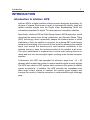
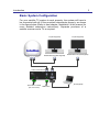
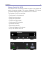
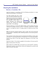
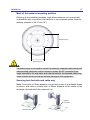
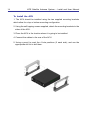
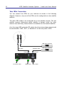
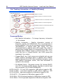
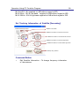
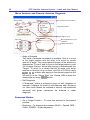
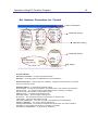
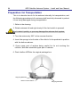
Intellian i6PE Serial Number This serial number will be required for all troubleshooting or service calls made regarding this product. Notice All Right Reserved ® ® Intellian i6PE and Intellian are the registered trademarks of Intellian Technologies, Inc., and should not be appropriated without permission by Intellian Technologies, Inc., and the information contained in this manual is the property of Intellian Technologies, Inc. Any and all parts of this manual shall not be reproduced and distributed in any form without prior written consent by Intellian Technologies, Inc. The information contained in this manual shall be subject to change at any time without notice due to the functional upgrades of the product. Copyright© Intellian Technologies, Inc. Doc. No. I6PE-DC V100 CONTENTS INTRODUCTION .............................................................................................. 1 INTRODUCTION TO INTELLIAN I6PE ................................................................... 1 FEATURES OF INTELLIAN I6PE ........................................................................... 4 BASIC SYSTEM CONFIGURATION ......................................................................... 5 INSTALLATION ................................................................................................ 4 SYSTEM COMPONENTS ....................................................................................... 4 TOOLS REQUIRED FOR INSTALLATION ................................................................ 7 PLANNING THE INSTALLATION............................................................................ 8 INSTALLING THE ACU ................................................................................. 13 CONNECTING THE SYSTEM TO A GPS ............................................................... 18 TARGET SATELLITE SETTING ............................................................................ 19 ADJUSTING THE LNB SKEW ANGLE (LINEAR POLARIZATION ONLY) ................ 20 OPERATION INSTRUCTION ....................................................................... 21 INTRODUCTION ................................................................................................ 21 OPERATION USING THE ACU .................................................................... 22 ACU SOFT KEYS ............................................................................................. 22 NORMAL MODE ............................................................................................... 22 SET UP MODE .................................................................................................. 26 OPERATION USING PC CONTROLLER PROGRAM ............................. 48 INTRODUCTION ................................................................................................ 48 PROGRAM INITIALING AND SERIAL PORT SETUP .............................................. 49 MAIN MENU – USING DEFAULT DUAL-SAT MODE ........................................... 50 SET SATELLITE INFORMATION .......................................................................... 51 MAIN MENU- USING ADVANCED TRI-SAT MODE ............................................. 53 SET SATELLITE INFORMATION .......................................................................... 54 CONTROLLER MENU ......................................................................................... 57 TROUBLESHOOTING ................................................................................... 62 PREPARATION FOR TRANSPORTATION ................................................ 64 WARRANTY ..................................................................................................... 65 APPENDIX : TECHNICAL SPECIFICATION ............................................ 66 Introduction 1 INTRODUCTION Introduction to Intellian i6PE Intellian i6PEis a digital satellite antenna system designed specifically for all types of vessels (Anchored or transit) to automatically identify, track and capture satellite signals from the Digital Video Broadcasting (DVB: the international standard for digital TV transmissions) compatible satellites. Specifically, Intellian i6PE has Wide Range Search (WRS) algorithm, which minimizes the search time during initialization, and Dynamic Beam Tilting (DBT) technology, which dynamically shapes the antenna beam to utilize stabilization. Once the satellite is acquired, the antenna DBT continuously measures the heading, pitch, and roll of the vessel by obtaining the satellite signal level around the antenna point, and transmits commands to the antenna motors to keep the antenna pointed at the satellite at all times. This active stabilization is enhanced by a conical scan tracking function to detect and lock onto the strongest signal, resulting in the clearest reception possible. Furthermore, the i6PE has expended its elevation angle from -15 ~ 90 degrees which enable the system to receive satellite signal at polar regions. The i6PE has a built-in GPS system which enhances the speed of satellite signals acquisitions. In addition, the i6PE provides the embedded auto skew angle control system to maintain the optimal signal strength and increase the quality of satellite receptions in weak satellite single coverage area. 2 i6PE Satellite Antenna System – Install and User Manual Features of Intellian i6PE Low elevation angle Intellian i6PE is primary designed for receiving satellite signal at polar regions with its low elevation angle design. With an extra pointing angle, Intellian i6PE can track satellite down to 15 and up to 90 degrees elevation. Enjoy satellite broadcasts at sea Intellian i6PE is the most modern antenna system that enables you to receive a high quality broadcasting signal at sea, where the atmospheric and environmental condition are very harsh. Fully automatic control system Fully automatic control system allows you to simply turn the power switch on, and have crystal clear, high quality satellite television in motion or at anchor. High quality antenna High tech parabolic antenna technology has been adopted for this antenna system, which is optimal for marine conditions. This enables you to receive the optimal signal level even when it is raining or snowing. Fast and efficient search for the satellite The WRS (Wide Range Search) algorithm allows for the antenna system to search the satellite within the shortest amount of time and to detect the satellite signal under any position and with any directional movement of the ship. Easy installation and outstanding reliability Intellian i6PE uses only one RF cable for installation. This makes installation easy. Power, RF and Data signals transfer from the antenna the ACU through this single cable. In addition, Intellian i6PE provides highly reliable system through the implementation of a modularized design and the usage of strictly proved components. Built-in GPS and Automatic Skew Angle control system Intellian i6PE has imbedded GPS and automatic skew control system to ensure that the antenna system is able to maintain the optimal signal strength. Introduction 3 Basic System Configuration For your satellite TV system to work properly, the system will have to be connected with all of the provided components properly, as shown in the figure below (Refer to next chapter „Installation‟ in this manual for more detailed connection instructions). Separate purchase of a satellite receiver and a TV is required. TV (Not Supplied) TV (Not Supplied) Satellite Receiver (Not Supplied) Satellite Receiver (Not Supplied) Antenna Control Unit PC( Not Supplied) DC Power on Vessel (DC-10.8-15.6V) NMEA GPS i6PE Satellite Antenna System – Install and User Manual 4 Installation The components of the Intellian i6PE have been designed to be modular so that it is suitable for simple installation on all types of vessels. System Components Antenna Unit The antenna of Intellian i6PE is composed with the following components for the optimum search and reception of the satellite signal. Mechanical Unit – manipulates the antenna to receive the optimal satellite signal regardless of the movement of the vessel. Control Unit – controls mechanical operation of the antenna. RF Unit – transmits the optimum satellite signal to the receiver. Radome – protects the antenna from the severe marine environment. Installation 5 Antenna Control Unit (ACU) The Antenna Control Unit (ACU) provides the power to the antenna and controls the various settings of the antenna. Additionally, VFD (Vacuum Fluorescent Display) allows for you to operate the ACU in the dark. The functions of the ACU are as follows: Provide power for the antenna unit Monitor the antenna status Change the target satellite Set up the user environment Set the current GPS information Set satellite information Move antenna manually Perform self-diagnosis of the antenna Set up the interface with a PC Front Rear i6PE Satellite Antenna System – Install and User Manual 6 Installation Kit Contain the items required for securing the antenna unit and ACU to your boat. Antenna Hex. Bolt 5EA Hex Head Wrench Bolt 5EA Flat Washer 5EA ACU Spring Washer 5EA Tapping Screw (Φ4x16L) 5EA Hex. Nut 5EA Machine Screw (Φ3x8L) 5EA Other Components No Components Size Q’ty - 2EA 1 ACU Bracket 2 RG6 (Antenna – ACU RF Cable) 15m 1EA 3 RG6 (ACU – IRD Cable) 3m 1EA 4 Power Cable 10m 1EA 5 PC Serial Cable 1.8m 1EA 6 NMEA Connector AK950-2 1EA 7 Power Connector AK950-3 1EA Hex Bolt M8x50L 5EA Tapping Screw ø4x16L 5EA Tapping Screw ø38L 5EA Flat Washer M8 5EA Spring Washer M8 5EA 8 9 Install CD - 1 EA 10 Manual - 1 EA 11 Mounting Template - 1 EA 12 Quick Installation Guide - 1EA Installation 7 Tools Required for Installation Power Drill Cross-Head Screwdriver Φ10mm Drill Φ80mm Hole Saw 11mm Spanner 13mm Spanner Pencil 5mm Allen key 8 i6PE Satellite Antenna System – Install and User Manual Planning the installation Selection of Installation Site Install the antenna in accordance with the following procedures to insure maximum performance of the antenna. The ideal antenna site has a clear view of the horizon/satellite all around. Please be sure there are no obstacles within 15 degrees above the antenna. Any obstacles located above a 15 degree elevation can prevent the antenna from tracking the satellite signal (Refer to the drawing). 15° Antenna Unit Obstacle Keep the antenna out of line with nearby radars, as their energy levels may overload the antenna front-end circuits. If necessary, position the antenna unit so it is at least four feet (1.2 meters) above or below the level of the radar. Make sure that the mounting surface is rigid, so that it will not flex when the vessel vibrates. If necessary, add a stiffening member to the mounting site to strengthen it. The movement of the antenna can be minimized by installing it at the center of the ship. For optimal performance of the antenna, it is not recommended to install at any corner of the ship, where the movement of the ship is the greatest. Install the bottom of the antenna parallel to the surface of the sea and fix tightly to the structure of the ship. When setting the antenna down, be careful not to have the RF connector. Striking the connector on the bottom directly will damage the connector and make connection impossible. Installation 9 Cables Before installing the system cables, you need to take the following points into consideration. All cables need to be well clamped and protected from physical damage and exposure to heat and humility. Cable with an acute bend is not allowed. Where a cable passes through an exposed bulkhead or deckhead, a watertight gland or swan neck tube should be used. Power requirements You need to follow the power requirements to avoid damage the system. Intellian i6PEhas been designed to work on a boat‟s power supply rated at 12VDC (acceptable range: 10.8~15.6 V DC). If your IRD(s) and television(s) require a 110V/240V AC power supply, you will need to install a suitable DC to AC converter to operate the unit(s) from your boat‟s DC power supply. Extending the cables The cables that have been supplied with your Intellian system should be of adequate length to complete the installation on most boats. Power Cable This cable supplied at a length of 10m. RF Cable This cable is supplied at a length of 15m. If a longer length is required you should replace this cable with an extended RF cable supplied by Intellian Technologies. WARNING Exceeding the indicted cable lengths will result in reduced performance of your system. i6PE Satellite Antenna System – Install and User Manual 10 Installation and Mounting of antenna The method of installation and mounting of antenna may vary with vessel design but the following procedures are applicable in most situations, and will result in a secure and effective installation. Confirmation of size prior to installation Confirm the height and diameter of the bottom surface of the antenna before installing it. The space must be sufficient for installing the antenna unit considering the height and diameter of the antenna. The height and the diameter of the bottom surface of the antenna are as shown in the following drawing. If possible, install the antenna using a power tower. 75.4cm (29.7”) Ø 70cm (27.5”) WARNING Before installing the antenna you have to remove the radome and remove the shipping foam from the antenna interior. Replace the radome before installation. The system functions will be abnormal if the radome is off. Installation 11 Mark of the antenna mounting position Referring to the mounting template, mark where antenna is to be mounted on board the ship (it must be a flat surface) or on a separate power tower by drawing a square of 30.37 cm (12”). 30.37cm (12”) 30.37cm (12”) WARNING If a power tower is not sued to mount the antenna, separate cable shock and waterproofing measures must be taken to protect the RF connector from begin exposed to the sea water and external shocks. An exposed cable may cause electric shock and cause serious damage to the equipment. Securing hole for bolts and cable way Make 4 bolt holes of 10mm diameter, one at each corner of a rectangle drawn as above, and make a circular hole of 80mm diameter at the center of the rectangle, through which the cable will run. ø 80mm Hole saw Ø 10mm Drill i6PE Satellite Antenna System – Install and User Manual 12 Connection of the RF cable Remove the rubber protector from RF connector. Connect the RF cable to the RF connector under the base plate through the access hole using a 11mm spanner. Be careful not to tighten it too much, as you may damage the connector. 11mm Spanner Antenna Unit RF Cable Optional WARNING Do not use excessive force when using the spanner, this will damage the threads. Be careful that the connectors do not contact the mounting surface of the antenna, this may cause a critical malfunction and serious damage to the equipment. Mounting the antenna Attach the antenna by using the hex head bolts (M8X50L), M8 spring washers, and M8 flat washers supplied. Antenna Unit Support Deck M8 Flat Washer M8 Spring Washer M8 Hex. Bolt 13mm Spanner Installation 13 Installing the ACU ACU dimensions 22.8cm (9”) 18.5cm (7.3”) 21.68cm (8.5”) 17.8cm (7”) 5.38cm (2.1”) 5.5cm (2.2”) Selection of Installation Site The ACU should be installed below deck, in a location that is : Dry, cool, and ventilated. Easy accessible from your main TV viewing area. 14 i6PE Satellite Antenna System – Install and User Manual To Install the ACU 1. The ACU should be installed using the two supplied mounting brackets which allow for a top or bottom mounting configuration. 2. Using the self tapping screws supplied, attach the mounting brackets to the sides of the ACU. 3. Place the ACU in the location where it is going to be installed. 4. Connect the cables to the rear of the ACU. 5. Using a pencil to mark the 4 hole positions (2 each side), and use the appropriate drill bit to drill them. Installation 15 Connecting the System Cables After installation and fixation of the antenna, connect the ACU to the antenna. Refer the drawing below to connect cables. SINGLE IRD Connection RF Cable ACU IRD Cable Antenna DC Power Cable NMEA GPS IRD (Not Supplied) Receiver PC( Not supplied) Connect the RF Cable (15m) from the RF 1 connector on the antenna to the ANT. RF1 connector on the rear of ACU. Connect the ACU-IRD Cable (3m) from the RECEIVER connector on the rear of the ACU to RF on the IRD. Connect the power cable (10m) from DC power connector on the rear of ACU to a power source at 12V DC . Press the POWER ON switch in front of the ACU to start the operation of the antenna system automatically. 16 i6PE Satellite Antenna System – Install and User Manual Twin IRDs Connection You can connect two IRDs for your antenna as shown in the following diagram. However, only one of the IRDs can be configured as a two satellite receiver. The other IRD needs to be configured as a one satellite receiver. The two satellite receiver determines which satellite is tracked, while the other receiver can watch any channel which is available from the tracked satellite. As in the single IRD option the RF cables from the antenna base plate should be connected to „LNB‟, „ANT‟, or „Satellite In‟ on the rear panel of IRD. IRD 1(Not Supplied) ACU IRD Cable RF Cable Antenna DC Power Cable NMEA GPS Receiver PC Cable IRD 2(Not Supplied) Installation 17 Multiple IRDs Connection In order to connect multiple IRDs to the antenna, you will need to purchase a suitable active multiswitch. The multiswitch has to be installed between the antenna unit and the IRDs as shown in the following diagram. ACU IRD Cable RF Cable Antenna Receiver Multi switch (Not supplied) DC Power Cable IRD1 NMEA GPS IRD 2 PC Cable IRD 3 IRD 4 ※ IRD 1~4 : Not supplied i6PE Satellite Antenna System – Install and User Manual 18 Connecting the system to a GPS For improved satellite tracking, you can connect your satellite TV system directly to your boat‟s NMEA 0183 GPS system. To do this you will need lengths of cable suitable for connecting to your GPS system and the green 2-way ACU GPS connector supplied with your Intellian i6PESatellite TV System. To connect the system to a GPS 1. Strip back the insulation of each cable and connect a cable to each terminal of the 2-way connector. 2. Tighten the locking screws. 3. Connect the cable from the +ve (positive) terminal of the ACU GPS connector to the NMEA OUT wire of the boat‟s GPS system. 4. Connect the cable from the –ve (negative) terminal of the ACU GPS connector to the ground wire of the boat‟s GPS system. 5. Refit the ACU GPS connector to the rear of the ACU. NMEA out (+) Ground (-) Installation 19 Target Satellite Setting You can select the target satellite to receive satellite signal from. If the target satellite is not on the list you will have to register the target satellite. GPS Setting You can input the GPS information through the ACU or the PC Program. To setting the GPS information, the antenna system has to be in „SET UP mode‟. For detailed instructions, please refer to page 38; „Setting the GPS‟, and page 59; „Set Antenna GPS and find Antenna Angle‟. Satellite registration You can register the target satellite through the ACU or the PC program. To register the target satellite, the antenna system has to be in „SET UP mode‟ and the required information is, Satellite name, Satellite Longitude, Method of Satellite Identification, Frequency of each of the band, Symbol Rate, Network ID, Power Change method. For detailed instructions, please refer to page 31; „Edit Satellite Information‟, page 53; „Set Satellite Information‟, and page 60; „Set Tracking Information of Satellite‟. Satellite Pair Selection You can select the Satellite Pair from the list through the ACU or the PC program. You can easily select the target satellite from the satellite pair. For detailed instructions please refer to page 29; „Setting the Satellite pair‟, page 53; „Set Satellite Information‟. Target Satellite Selection Choose the target satellite from the Satellite Pair. When selecting through the ACU, you have to press the left button to select the target satellite while the antenna system is in either „Searching Mode‟ or „Tracking Mode‟. When using the PC program you can select either satellite „A‟ or satellite „B‟ from „Tracking Satellite‟ at anytime. 20 i6PE Satellite Antenna System – Install and User Manual Adjusting the LNB Skew Angle (Linear polarization only) Auto Skew Angle Adjustment for i6PE Intellian i6PE with an embedded auto skew angle control system. Therefore, manual adjustment of skew angle by user is not required. The skew angle is continuously adjusted automatically through the calculation of the optimum skew angle by using the information of the targeted satellite and the output value from the GPS sensor. Together with such location information of the ship as ship‟s longitudinal and latitudinal position change from movement the skew angle will be adjusted accordingly. The skew angle of LNB is shown from the ACU and GUI Program. Skew sensor LNB Skew Motor 21 Operation Instruction Operation Instruction Introduction This section of the handbook describes how to set up your Satellite TV System after installation using the ACU or PC controller program and includes the following functions: System start up. Changing the default satellite. Monitoring the antenna status. Setting sleep mode. Entering setup mode. Setting the satellite pair. Editing satellite information. Setting the antenna parameter. Setting the LNB local frequency. Setting GPS. Setting the DiSEqC method. Display versions. Display power status. Setting antenna go position. Setting antenna move step. Setting remote control. Setting the factory default parameters. Performing diagnostic tests. WARNING Note: Many of the above functions will only be required only after initial installation of your system. Refer to the Quick Installation Guide before operating the system. i6PE Satellite Antenna System – Install and User Manual 22 Operation Using the ACU ACU Soft Keys BACK POWER BACK Press to select On-screen option Normal Mode Start Up With the system installed and power applied, the ACU screen will show the following sequence: INITIALIZE ACU INTELLIAN i6 PE 1.Communication is being established between the antenna and the ACU. The ACU initialized. INITIALIZE ANTENNA INTELLIAN i6 PE 2. The antenna is initialized. SEARCH B:DTV119 A: DTV101 SETUP 3. The antenna is searching for Satellite A. TRACKING B:DTV119 A: DTV101 SETUP 4. The antenna has located the satellite and is now tracking. Operation Using the ACU 23 Change of Target Satellite Your antenna is programmed with two candidates of target satellites as default Dual-sat mode. Use advanced Tri-sat mode for targeting three satellites. To change the target satellite, press LEFT soft key. The target satellite is changed and is automatically tracked by the antenna. Default Dual-sat Mode TRACKING A:DTV101 B:DTV119 SETUP 1. Press LEFT soft key for tracking Satellite B. TRACKING A:DTV101 2. The antenna is tracking Satellite B. B:DTV119 SETUP 24 i6PE Satellite Antenna System – Install and User Manual Advanced Tri-sat Mode TRACKING A:DTV101 A: DTV101 DTV119 B:DTV119 SETUP DTV110# 1. Press LFET soft key for tracking Satellite B. TRACKING B: DTV119 DTV110# DTV101 2. The antenna is tracking Satellite B. TRACKING B: DTV119 DTV110# DTV101 3. Press LFET soft key for tracking Satellite C. TRACKING C: DTV110# DTV101 DTV119 4. The antenna is tracking Satellite C. * Register a key on your remote control to track alternative target satellites. See page 44. Operation Using the ACU 25 Monitoring the current status of the antenna While POWER ON to Intellian i6/i6P, ACU displays the status of the antenna. The various ACU displays may be shown according to the current status of the antenna. SEARCH A: DTV101 B:DTV119 SETUP 1. The antenna is searching for Satellite A. TRACKING A:DTV101 B:DTV119 SETUP 2. The antenna is tracking Satellite A. ANTENNA IS UNWRAPING B:DTV119 SETUP 3. The antenna is unwrapping the cable. TRACKING A:DTV101 B:DTV119 SETUP 4. The antenna is again tracking satellite A. Press center soft key to display position detail. AZ : ###.# EL : ##.# SIGNAL:###● [VL] 5. Antenna position detail and signal strength are displayed. ###.##E ##.##N SETUP 6. Press center soft key to display current GPS information. Press SETUP to return to main setup mode. i6PE Satellite Antenna System – Install and User Manual 26 Sleep Mode If the antenna lost the tracking satellite in sleep mode, sleep mode is cancelled. TRACKING :A:DTV101 B:DTV119 SETUP 1. Press BACK to enter sleep mode. TRACKING :A:DTV119 ▌B:DTV119 SETUP 2. Press Back again for exiting sleep mode. * Register a key on your remote control to change sleep mode. See page 44. Set Up Mode Begin Set-Up Mode To enter the Set-up Mode simply follow the instructions below: TRACKING B:DTV119 A:DTV101 SETUP 2. Press YES to enter setup mode. SETUP MODE? YES 1. With the antenna tracking . Press SETUP. NO SET SAT PAIR ? PREV YES NEXT 3. Press Yes to set the satellite pair. Operation Using the ACU 27 Setting the Satellite Pair You can change the satellite pair if you decide to receive satellite television service from a different service provider. Example1. Changing the target satellite without using DiSEqC: 1. Press YES to enter setup mode. SETUP MODE? YES NO SET SAT PAIR ? PREV YES NEXT 2. Press YES to set satellite pair. SET TRIPLE SAT ? YES NO 3. Press YES to set triple satellite. SAT A : DTV101 PREV SELECT NEXT 4. Set satellite A Press PREV to show previous satellite name. Press SELECT to set chosen satellite to SAT A. Press NEXT to show next satellite name. SAT B : DTV119 PREV SELECT NEXT 5. Set satellite B Press PREV to show previous satellite name. Press SELECT to set chosen satellite to SAT B. Press NEXT to show next satellite name. SAT C: DTV110# PREV SELECT NEXT 6. Set satellite C Press PREV to show previous satellite name. Press SELECT to set chosen satellite to SAT C. Press NEXT to show next satellite name. SAVE ? YES NO 7. Press YES to save selections. Press NO to cancel and return to main setup mode. i6PE Satellite Antenna System – Install and User Manual 28 Example2. Changing the target satellite using DiSEqC: 1. Press YES to enter setup mode. SETUP MODE? YES NO SET SAT PAIR ? PREV YES NEXT 2. Press YES to set satellite pair. SAT A : DTV101 PREV SELECT NEXT 3. Set satellite A Press PREV to show previous satellite name. Press SELECT to set chosen satellite to SAT A. Press NEXT to show next satellite name. SAT B : DTV119 PREV SELECT NEXT 4. Set satellite B Press PREV to show previous satellite name. Press SELECT to set chosen satellite to SAT B. Press NEXT to show next satellite name. SAT A* : DTV101 PREV SELECT NEXT 5. Set satellite A* when DiSEqC is active from IRD. Press PREV to show previous satellite name. Press SELECT to set chosen satellite to SAT A*. Press NEXT to show next satellite name. SAT B* : DTV119 PREV SELECT NEXT 6. Set satellite B* when DiSEqC is active from IRD. Press PREV to show previous satellite name. Press SELECT to set chosen satellite to SAT B*. Press NEXT to show next satellite name. SAVE ? YES NO 7. Press YES to save selections. Press NO to cancel and return to main setup mode. Operation Using the ACU 29 Edit Satellite information It is possible to modify the existing satellite information and input new satellite information into the ACU as well. It is not recommended for a novice satellite service user to use this mode. 1. Press YES to enter setup mode. SETUP MODE? YES NO SET SAT PAIR ? PREV YES NEXT 2. Press NEXT twice to enter edit satellite info mode. x2 EDIT SAT INFO ? PREV YES NEXT 3. Press YES to edit satellite info. SAT NAME : DTV101 PREV SELECT NEXT 4. Set the satellite name. PREV – Shows previous satellite name. SELECT – Select the displayed satellite for editing. NEXT – Shows next satellite name. Press ENTER to move to next screen. SAT NAME : DTV101 INPUT + 5. Input the satellite name. + Increases the value. - decreases the value. Change the underscored digit using the +/- buttons. Press INPUT to accept the value and move to next digit. Press BACK to move to previous digit. SAT NAME : DTV101 INPUT + 6. Press ENTER to move to next screen. Press BACK to return previous screen. LONGITUDE 124.00 E INPUT + 7. Input the satellite position. +increases a value. – decreases a value. Change the underscored digit using the +/- buttons. Press INPUT to accept the value and move to next digit. Press BACK to move to previous digit. 30 i6PE Satellite Antenna System – Install and User Manual VER LOW 12598 21096 INPUT + 8. Input the tracking frequency (MHz) and symbol rate (KHz) for vertical low band. VER LOW NID 0x0003 INPUT + 9. Input the network ID (NID) for vertical low band. HOR LOW 12523 21096 INPUT + 10. Input the tracking frequency (MHz) and symbol rate (KHz) for horizontal low band. HOR LOW NID 0x0003 INPUT + 11. Input the network ID (NID) for horizontal low band. VER HIGH 12598 21096 INPUT + 12. Input the tracking frequency (MHz) and symbol rate (KHz) for vertical high band. VER HIGH NID 0x0003 INPUT + 13. Input the network ID (NID) for vertical high band. HOR HIGH 12523 21096 INPUT + 14. Input the tracking frequency (MHz) and symbol rate (KHz) for horizontal high band. Operation Using the ACU 31 HOR HIGH NID 0x0003 INPUT + VERIFY : DVB DECODE PREV SELECT NEXT VOLTAGE: AUTO PREV SELECT NEXT DISEQC: ONLY 22KHZ PREV SELECT NEXT SAVE ? YES NO 15. Input the network ID (NID) for horizontal high band. 16. Select the verification method 1) of tracking satellite. PREV – Shows previous method. SELECT – Set the displayed method. NEXT – Shows next method. 17. Select the voltage supplymethod 2) to LNB (AUTO recommended ) 18. Select the DISEQC method 3) (AUTO recommended) 19. Press YES to save the input information. Press NO to cancel and return to main setup mode. 1) Verification method SIGNAL – use only signal level for tracking DVB LOCK – use only DVB Lock signal for tracking DVB DECODE – verify satellite using DVB decoding method for tracking DSS DECODE – decode only DSS Lock signal for tracking 2) Voltage supply method AUTO- change voltage to LNB by IRD voltage ONLY 13V – always supply 13V to LNB ONLY 18V – always supply 18V to LNB 3) DISEQC method AUTO – change signal to LNB by IRD DISEQC ONLY 0KHZ – always supply 0kHz to LNB ONLY 22KHZ - always supply 22kHz to LNB i6PE Satellite Antenna System – Install and User Manual 32 Setting the Antenna Parameters It is not recommended for a novice satellite service user to use this mode. Consult Intellian for changing antenna parameters. 1. Press YES to enter setup mode. SETUP MODE? YES NO SET SAT PAIR ? PREV YES NEXT 2. Press NEXT three times to enter set antenna parameter mode. x3 SET ANT PARAMETER? PREV YES NEXT PARAM: SCAN OFF PREV YES NEXT WRS LEVEL : 0500 INPUT + SATNAMESAVE : DTV101 ? YES INPUT NO + 3. Press YES to set antenna parameter. 4. Select the PARAM 1) – SCAN OFF PREV – Shows previous parameter. SELECT – Set the displayed parameter. NEXT – Shows next parameter. Press ENTER to move to next screen. 5. Input the WRS LEVEL. +increases the value. – decreases the value. Change the underscored digit using the +/- buttons. Press INPUT to accept the value and move to next digit. Press BACK to move to previous digit. Press ENTER to move to next screen. 6. Press YES to save the input information. Press NO to cancel and return to main setup mode. Operation Using the ACU 1) Parameter Setting method SCAN OFFSET – The actual angle between the marked point on the sub-reflector and the datum. TRACK SCALE – To control the tracking speed while antenna is tracking the satellite. High Track Scale value resulting in high tracking speed. DETECT LEVEL – The basic single detection level. TRACKING LEVEL – The basic signal tracking level EL ADJUST – The mechanical tolerance compensation of elevation limit. WRS LEVEL – The basic WRS detection level. POWER THRESHOLD – The value to identify Vertical/Horizontal or RHCP/LHCP. DISEQC LEVEL – The value to identify 22KHz tone. OFFSET RH-LH – The difference value between RHCP/LHCP and SCAN OFFSET. USE WRS – To apply WRS while antenna is searching for satellite. OFFSET DIFFERENCE – To apply Offset Difference. 33 i6PE Satellite Antenna System – Install and User Manual 34 Setting the LNB local frequency It is possible to select a local frequency from ACU. It is not recommended for a novice satellite service user to use this mode. CASE 1. Single band LNB is used. 1. Press YES to enter setup mode. SETUP MODE? YES NO SET SAT PAIR ? PREV YES NEXT 2. Press NEXT four times to enter set local frequency mode. x4 SET LOCAL FREQ? PREV YES NEXT LNB TYPE : SINGLE PREV SELECT NEXT LOCAL FREQ: #####MHz INPUT + 3. Press YES to set local frequency. 4. Select the LNB Type 1) – SINGLE. PREV – Shows previous LNB type. SELECT – Set the displayed LNB type. NEXT – Shows next LNB type. Press ENTER to move to next screen. 5. Input the local frequency of LNB. +increases the value. – decreases the value. Change the underscored digit using the +/buttons. Press INPUT to accept the value and move to next digit. Press BACK to move to previous digit. Press ENTER to move to next screen. SAVE ? YES NO 6. Press YES to accept the data. Press NO to cancel and return to main setup mode. Operation Using the ACU 35 CASE 2. Universal LNB is used. (Low band local frequency-9750 MHz/ High bnad local frequcny 10600 MHz) 1. Press YES to enter setup mode. SETUP MODE? YES NO SET SAT PAIR ? PREV YES NEXT 2. Press NEXT four times to enter set local frequency mode. x4 SET LOCAL FREQ? PREV YES NEXT LNB TYPE : UNIVERSAL PREV SELECT NEXT SAVE ? YES NO 3. Press YES to set local frequency. 4. Select the LNB Type 1) – UNIVERSAL. PREV – Shows previous LNB type. SELECT – Set the displayed LNB type. NEXT – Shows next LNB type. Press ENTER to move to next screen. 5. Press YES to accept the data. Press NO to cancel and return to main setup mode. 1) LNB Type SINGLE: Single Band LNB Asia 11300 MHz, Japan 10678MHz, Korea 10750MHz, America 11250MHz UNIVERSAL : Universal LNB Low band local frequency -9750 MHz High band local frequency -10600 MHz i6PE Satellite Antenna System – Install and User Manual 36 Setting the GPS It is possible to set up and modify the GPS information, which enhances the antenna functionality. 1. Press YES to enter setup mode. SETUP MODE? YES NO SET SAT PAIR ? PREV YES NEXT 2. Press NEXT to enter GPS setup mode. x1 SET GPS ? PREV YES 3. Press YES to set GPS. NEXT LONGITUDE ###.## E INPUT + 4. Input the longitude data. +increases the value. – decreases the value. Change the underscored digit using the +/- buttons. Press INPUT to accept the value and move to next digit. Press BACK to move to previous digit. LONGITUDE ###.## E INPUT + 5. Press ENTER to move to next screen. Press BACK to move to previous screen. LATITUDE ##.## N INPUT + 6. Input the latitude data. +increases the value. – decreases the value. Change the underscored digit using the +/- buttons. Press INPUT to accept the value and move to next digit. Press Back to move to previous digit. SAVE ? YES NO 7. Press YES to accept data. Press NO to cancel and return to main setup mode. Operation Using the ACU 37 Setting the DiSEqC Method DiSEqC selection can be made from ACU. It is not recommended for a novice satellite service user this mode. 1. Press YES to enter setup mode. SETUP MODE? YES NO SET SAT PAIR ? PREV YES NEXT 2. Press NEXT five times to enter DISEQC mode. x5 USE DISEQC ? PREV YES NEXT DO NOT USE DISEQC PREV SELECT NEXT SAVE ? YES NO 3. Press YES to use DISEQC. 4. Select the DiSEqC Method 1) PREV – Shows previous DiSEqC Method. SELECT/ENTER – Set the displayed DiSEqC method. NEXT– Shows next DiSEqC Method. Press ENTER to move to next screen. 5. Press YES to accept the selection. Press NO to cancel and return to main setup mode. 1) DiSEqC method DO NOT USE DISEQC – DiSEqC is not in using. USE TO CHANGE BAND – DiSEqC is used to change to low and high band. USE TO CHANGE SAT – DiSEqC is used to change tracking satellite. i6PE Satellite Antenna System – Install and User Manual 38 Display Versions This sequence enables you to see what version of antenna and ACU software version are installed on your system. 1. Press YES to enter setup mode. SETUP MODE? YES NO SET SAT PAIR ? PREV YES NEXT 2. Press NEXT six times to enter the view version mode. x6 VIEW VERSION ? PREV YES NEXT 3. Press YES to view version. SF-601S S/N: 0000000000 EXIT 4. Antenna product name and S/N are shown. Press center soft key to view antenna software version. Press EXIT to return to main setup mode. ANT S/W VER : 4.00 S/N: 0000000000 EXIT 5. Antenna software version and S/N are shown. Press center soft key to view ACU software version. Press EXIT to return to main setup mode. ACU S/W VER : 0.01 S/N: 0000000000 EXIT 6. ACU software version and S/N are shown. Press EXIT to return to main setup mode. Operation Using the ACU 39 Display Power 1. Press YES to enter setup mode. SETUP MODE? YES NO SET SAT PAIR ? PREV YES NEXT 2. Press NEXT seven times to enter the view power mode. x7 VIEW POWER ? PREV YES NEXT 3. Press YES to view power. ACU POWER : 27.1 V EXIT 4. ACU Voltage is shown. Press center soft key to view antenna voltage. Press EXIT to return to main setup mode. ANT POWER : 25.9 V EXIT 5. Antenna Voltage is shown. Press center soft key to view IRD Voltage and frequency. Press EXIT to return to main setup mode. IRD : 18V + ##kHz EXIT 6. IRD Voltage and frequency are shown. Press EXIT to return to main setup mode. i6PE Satellite Antenna System – Install and User Manual 40 Setting Antenna Go Position The antenna can be controlled manually by using ACU. 1. Press YES to enter setup mode. SETUP MODE? YES NO SET SAT PAIR ? PREV YES NEXT 2. Press NEXT nine times to enter the antenna go position mode. x9 ANT GO POSITION? PREV YES NEXT GO TO - AZ : ###.# INPUT + GO TO EL : ###.# INPUT + GOTO POSITION ? YES NO AZ:###.# EL:###.# EXIT 3. Press YES to go position. 4. Input position value for azimuth (AZ) axis. + increases the value. – decreases the value. Change the underscored digit using the +/- buttons. Press INPUT to accept the value and move to next digit. Press BACK to move to previous digit. Press ENTER to move to next screen. 5. Input position value for elevation (EL) axis. + increases the value. – decreases the value. Change the underscored digit using the +/- buttons. Press INPUT to accept the value and move to next digit. Press BACK to move to previous digit. Press ENTER to move to next screen. 6. Press YES to move the antenna to input position. Press NO to return to the Antenna Go Position mode. 7. Press EXIT to return to main setup mode. Operation Using the ACU 41 Setting Antenna Move Step The antenna may be moved by 1° step manually by using ACU. 1. Press YES to enter setup mode. SETUP MODE? YES NO SET SAT PAIR ? PREV YES NEXT 2. Press NEXT ten times to enter the antenna move step mode. x10 ANT MOVE STEP ? PREV YES NEXT 3. Press YES to move step. STEP AZ : ###.# CCW EL CW 4. Move the antenna in the azimuth (AZ) axis. CW – Move the antenna clockwise. CCW – Move the antenna counter-clockwise. EL – Go to elevation control screen. STEP EL : ##.# DOWN EXIT UP 5. Move the antenna in the elevation (EL) axis. UP – Move the antenna up. DOWN – Move the antenna down. EXIT – Return to Antenna Move Step mode. i6PE Satellite Antenna System – Install and User Manual 42 Setting Remote Control 1. Press YES to enter setup mode. SETUP MODE? YES NO SET SAT PAIR ? PREV YES NEXT 2. Press NEXT eight times to enter remote control setting mode . x8 SET REMOCON ? PREV YES NEXT 3. Press YES to set remote control. FUNC : CHANGE SAT NEXT SELECT EXIT 4. Select the Function 1) NEXT – Shows next function. FUNC : SLEEP MODE NEXT SELECT EXIT PRESS A REMOTE KEY BACK EXIT 5. SELECT/ENTER –Registers a key on remote control . 6. Point remote control to ACU . Press any key on remote control for selected function and press same key again for confirmation. Press BACK to move to previous screen. Press EXIT to return to main setup mode. Operation Using the ACU FAILED - TRY AGAIN 43 7. If failed to press same key twice, TRY AGAIN will be displayed. THAT KEY IS USING 8. If failed to register a free key, KEY IS USING will be displayed. REMOTE KEY REGISTED 9. REMOTE KEY REGISTED will be displayed if key has been properly registered. FUNC : CHANGE SAT NEXT SELECT EXIT 10. Press NEXT to shows next function. Press EXIT to return to main setup mode. 1) Function CHANGE SAT SLEEP MODE CLEAR REGISTERED KEY Change the target satellite. Enter sleep mode. Clear registered key. i6PE Satellite Antenna System – Install and User Manual 44 Executing Antenna Diagnosis It is possible to see the antenna status by reviewing the result of diagnosis of the antenna. Refer to the following codes, to understand the diagnosis results. 1. Press YES to enter setup mode. SETUP MODE? YES NO SET SAT PAIR ? PREV YES NEXT 2. Press NEXT eleven times to enter the antenna diagnosis mode. x11 ANT DIAGNOSIS ? PREV YES NEXT 3. Press YES to diagnosis antenna. CODE 101 TESTING. RESULT: ? EXIT 4. CODE 101 is being tested. Press EXIT to return to main setup mode. CODE 101 PASSED. RESULT: 1 EXIT 5. CODE1) 101 is pass. Press EXIT to return to main setup mode. Operation Using the ACU 45 CODE 101 : Communication between antenna and antenna control unit is tested. If failed, check the power and data cable. CODE 102 : AZ CW limit is tested. If failed, check the limit sensors, motor ,and belt for AZ axis. CODE 103 : AZ CCW limit is tested. If failed, check the limit sensors, motor ,and belt for AZ axis. CODE 104 : EL axis is tested. If failed, check the limit sensors, motor ,and belt for EL axis. CODE 105 : Sub-reflector is tested. If failed, check the sub-reflector. CODE 106 : LNB is tested. If failed, check the LNB and control board. CODE 107: Skew System tested. If failed, check the control board, skew motor ,and skew sensor CODE 108 : Antenna Input Power tested. If failed, check the RF cable. CODE 109 : ACU Power tested. If failed, check the ACU power cable and Input DC power. CODE 110 : IRD Power tested. If failed, check the ACU to IRD cable and IRD power. RESULT STATUS : ● is pass. Number is fail(● ● 3 ● ● ● ● 8 ● ●). And ? Is Testing. i6PE Satellite Antenna System – Install and User Manual 46 Setting Region 1. Press YES to enter setup mode. SETUP MODE? YES NO SET SAT PAIR ? PREV YES NEXT 2. Press NEXT twelve times to enter the load region information mode. x12 LOAD REGION INFO? PREV YES NEXT CONTINENT: EUROPE PREV SELECT NEXT REGION : ITALY PREV SELECT NEXT LOAD? YES LOADING : ▐ ▐ DO NOT TURN OFF! NO 3. Press YES to load region information. 4. Select the continent1). PREV – Shows previous continent. SELECT– Select the displayed continent for editing. NEXT – Shows next continent. 5. Select the region 2). PREV – Shows previous region. SELECT– Select the displayed region for editing. NEXT – Shows next region . 6. Press YES to accept the selection. Press NO to cancel and return to main setup mode 7. After loading, auto restart. 1) CONTINENT N. AMERICAN, S.AMERICAN, EUROPE, ASIA.. 2) REGION New York, Miami, UK, JAPAN.. Operation Using the ACU 47 Setting the factory default parameters Initialize all of the antenna information to the factory set up. 1. Press YES to enter setup mode. SETUP MODE? YES NO SET SAT PAIR ? PREV YES NEXT 2. Press NEXT thirteen times to enter the default setting mode. x13 SET DEFAULT ? PREV YES NEXT 3. Press YES to set default parameters. i6PE Satellite Antenna System – Install and User Manual 48 OPERATION USING PC Controller Program Introduction GUI Software of Intellian i6PE has been coded for the user to easily set up the antenna by using the user‟s personal computer. Using the GUI program enables the user to easily monitor and modify the information of antenna, satellite and GPS. Additionally, the detail diagnostic method of the antenna is provided by the GUI program. To start this GUI program, 1. Connect one end of PC serial cable to the serial port on the computer. 2. Connect the other end of the PC serial cable to the “PC Interface” on the rear of ACU. 3. Execute GUI program by inserting the CD-ROM supplied into the CD-ROM drive of the computer. 4. After turning on the power of the ACU, if the blue status circle does not change to „Search‟ or „Tracking‟ from „Initialize‟, then you have to change the “PC Interface” terminal of ACU for PC program use rather than GPS use. Operation Using PC Contoller Program 49 Program Initialing and Serial Port Setup The communication between the ACU and antenna must be established as the first step in order to start setting your antenna. Baudrate setting Communication status display Serial port setting Connect/Disconnect Button Command Button Baud Rate Setting – To display communication speed. Connection Status Display – To display communication port between ACU and PC. Serial Port Setting – To select serial port to be used. Connect/ Disconnect – To establish communication between PC and ACU. 50 i6PE Satellite Antenna System – Install and User Manual Main Menu – Using Default Dual-sat Mode Controller Menu Antenna status monitoring Select & Monitor target satellite Satellite pair DTV101 – SAT A without DiSEq C DTV119 – SAT B without DiSEq C Load Default 1 ) Update Default 2 ) Local frequency Signal strength Antenna Status Monitoring Search – Antenna is searching for the selected satellite. Tracking – Antenna is tracking the selected satellite. Initialize – Antenna or the ACU is initializing. Unwrap – Antenna is unwrapping the wire. Setup – Antenna is in setup mode. Comm. – Antenna is possible communication. Definition of Program Command Buttons Restart – To exit setup mode and restart antenna again. Setup – To enter the setup mode. Get Antenna Information – To indicate the information on display after receiving it input to the antenna. Factory Setting – To initialize all antenna information to the default as same as ex-factory status. Load Default – To show the up-to-date information input to PC program on display. Update Default – To update the antenna information by the up-to-date input to PC program. Operation Using PC Contoller Program 51 Set Satellite Information Satellite name and longitude Satellite Verif ication method Select Triple Satellite Register satellite f or tracking DiSEqC using method Select LNB type Set local f requency of LNB Satellite Information The name, longitude and confirmation method of the satellite is displayed when a satellite is selected in the list box. Push “Edit Satellite Information” button to update the information on modifying the value. DiSEqC When the operation method of DiSEqC is selected to “Change Band”, DiSEqC may be used for updating the local frequency and to “Change Satellite”, for updating the target satellite. Registration of target satellite In case that the DiSEqC is selected to “Not Use” or “Change Band”, only “Register for Sat A” and “Register for Sat B” may be registered. Pushing or button after selecting the satellite in the list box makes it possible to register A or B. In case that DiSEqC is selected to “Change Satellite”, “Register for Sat A” and “Register for Sat B” are activated and the target satellite when DiSEqC is available may be registered by pushing and buttons. Local Frequency In case that DiSEqC is selected to “Change Band”, be sure to push the “Universal LNB” button. In case that the DiSEqC is selected to “Not Use” or “Change Satellite”, be sure to push “Si ngle Band” button and key in into the Local Frequency, and then push “ Set Local Frequency” button. 52 i6PE Satellite Antenna System – Install and User Manual Command Button Edit Satellite Information – To modify the satellite information. Register for Sat A – To register a satellite to satellite A. Register for Sat B – To register a satellite to satellite B. Not Use – Do not use DiSEqC. Change Band – To use DiSEqC to change band. Change Satellite – To use DiSEqC to change the satellite. Singe Band – Antenna in use of Single LNB. Universal Band – Antenna in use of universal LNB. Set Local Frequency – To select local frequency of LNB. Operation Using PC Contoller Program 53 Main Menu- Using Advanced Tri-sat Mode Controller Menu Antenna status monitoring Select & Monitor target satellite Satellite pair DTV101 – SAT A without DiSEq C DTV119 – SAT B without DiSEq C DTV110# – SAT C with DiSEq C 1 Load Default ) Update Default2 ) Local frequency Signal strength Antenna Status Monitoring Search – Antenna is searching for the selected satellite. Tracking – Antenna is tracking the selected satellite. Initialize – Antenna or the ACU is initializing. Unwrap – Antenna is unwrapping the wire. Setup – Antenna is in setup mode. Comm. – Antenna is possible communication. Definition of Program Command Buttons Restart – To exit setup mode and restart antenna again. Setup – To enter the setup mode. Get Antenna Information – To indicate the information on display after receiving it input to the antenna. Factory Setting – To initialize all antenna information to the default as same as ex-factory status. Load Default – To display the up-to-date information input to PC program. Update Default – To update the antenna information by the up-to-date information input to PC program. i6PE Satellite Antenna System – Install and User Manual 54 Set Satellite Information Satellite name and longitude Satellite Verif ication method Select Triple Satellite Register satellite f or tracking DiSEqC using method Select LNB type Set local f requency of LNB Satellite Information The name, longitude and confirmation method of the satellite is displayed when a satellite is selected in the list box. Push “Edit Satellite Information” button to update the information on modifying the value. DiSEqC When the operation method of DiSEqC is selected to “Change Band”, DiSEqC may be used for updating the local frequency and to “Change Satellite”, for updating the target satellite. Registration of target satellite In case that Tri-sat Mode is selected and the DiSEqC is selected to “Not Use, only “Register for Sat A”, “Register for Sat B” and “Register for Sat A” and “Register for Sat B” are activated and the target satellite when DiSEqC is available may be registered by pushing and buttons. Local Frequency In case that DiSEqC is selected to “Change Band”, be sure to push the “Universal LNB” button. In case that the DiSEqC is selected to “Not Use” or “Change Satellite”, be sure to push “Single Band” button and key in into the Local Frequency, and then push “ Set Local Frequency” button. Operation Using PC Contoller Program 55 Command Button Edit Satellite Information – To modify the satellite information. Tri- sat Mode – To use Triple Satellite. Register for Sat A – To register a satellite to satellite A. Register for Sat B – To register a satellite to satellite B. Register for Sat C – To register a satellite to satellite C. Not Use – Do not use DiSEqC. Change Band – To use DiSEqC to change band. Change Satellite – To use DiSEqC to change the satellite. Singe Band – Antenna in use of Single LNB. Universal Band – Antenna in use of universal LNB. Set Local Frequency – To select local frequency of LNB. Load and Update Default Command Button 1) Load Default: Click “load default” button to select *.rif file according to your region. i6PE Satellite Antenna System – Install and User Manual 56 2) Update Default: Click “Update default” button to open update default Dialogue. Click “yes” button to update the system. 3) Click “confirm / yes” button to complete the update. Operation Using PC Contoller Program 57 Controller menu Set Antenna GPS and Find Antenna Angle Antenna makes use of GPS information to search satellite quickly. The more precise the GPS information is, the quicker the antenna is able to search the satellite. The method to input information into GPS is to push “Set GPS” button after keying in the latitude and longitude information on “City GPS”. Pushing “Add City” button stores the GPS information. By selecting the stored region in the list box, the GPS information of such region is displayed. The Intellian i6PEsatellite TV antenna system utilizes GPS data to locate the satellite faster. Position stored in Antenna GPS Message Satellite Longitude Calculated Angle City GPS data Command Buttons Load GPS Files – Reads in the various city information from the GPS files. Add City – Adds the name of city and its GPS information to GPS files Delete City – Deletes the name of city and its GPS information from the GPS files. Set GPS – Inputs the indicated GPS information on display to antenna. Find Angles & Skew Antenna GPS – Finds the current antenna angles and Skew angle in relation to the longitude of satellite and GPS. Find Angles & Skew City GPS – Finds the current city angles and Skew angle in relation to the latitude of satellite and GPS. 58 i6PE Satellite Antenna System – Install and User Manual Set Tracking Information of Satellite [Primary] Satellite to be edited Satellite inf ormation f or Vertical & Low band Satellite inf ormation f or Horizontla & Low band Satellite inf ormation f or Vertical & High band Satellite inf ormation f or Horizontal & High band Power supplying method DiSEqC using method Command Button Edit Satellite Information – To change frequency information of the antenna Satellite Information – Satellite information consists of frequency, symbol and NID(Network ID) of a transponder in tracking satellite. There are four groups of satellite information. „Vertical/RHCP‟ is applied when IRD supply 13V, and „Horizontal/LHCP‟ is applied when IRD supply 18V. „LOW‟ is applied when DiSEqC signal is not detected from IRD, „HIGH‟ is applied when DiSEqC signal is detected from IRD. If you select „Not Use‟ or „Change Satellite‟, two „HIGH‟ groups are inactivated. If you select Change Band‟, two „High‟ groups are activated and you can modify satellite information which is applied when DiSEqC signal is detected from IRD. After modifying information, press „Edit Satellite Information‟ button, then new information is updated in the antenna. Pol & Band Control – The power controls 13V, Vertical (RHCP) and 18V, Horizontal (LHCP) bands. The Band controls High and Low bands. (AUTO RRECOMMEDED) AUTO & AUTO : 13V and 18V supplied to LNB without regard to IRD. AUTO & 0KHz : Low band supplied to LNB without regard to IRD AUTO & 22KHz : High band supplied to LNB without regard to IRD 13V & AUTO : 13V supplied to LNB without regard to IRD. 13V & 0KHz :13V & Low band supplied to LNB without regard to IRD. 13V & 22KHz :13V & High band supplied to LNB without regard to IRD. Operation Using PC Contoller Program 59 18V & AUTO :18V supplied to LNB without regard to IRD. 18V & 0KHz : 18V & Low band supplied to LNB without regard to IRD 18V & 22KHz :18V & High band supplied to LNB without regard to IRD. Set Tracking Information of Satellite [Secondary] Satellite to be edited Satellite inf ormation f or Vertical & Low band Satellite inf ormation f or Horizontla & Low band Satellite inf ormation f or Vertical & High band Satellite inf ormation f or Horizontal & High band DiSEqC using method Command Button Edit Satellite Information – To change frequency information of the antenna. 60 i6PE Satellite Antenna System – Install and User Manual Move Antenna and Execute Antenna Diagnosis The antenna current position Diagnosis results Target angle to go to Move the antenna in f our directions Skew Inf ormation Angle of Antenna Two kinds of antenna movement is available. One is to move to the target position and the other is to move by certain amount of angle. The current position(angle) of the antenna is displayed as “Current” and to move to the target position, push “Go to target Position” button after keying in desired angle into “Target”. To move to a certain amount of angle only, move antenna to direction of up or down, and CW or CCW by using buttons after keying in the desired angle into the AZ and EL in the “Mover Step” box. Rotate LNB to direct the skew angle by using button. Self-Diagnosis If “Diagnosis” button is pressed to carry out self- diagnosis of antenna, it displays the result of self-diagnosis after carrying it out. Blue circle means the antenna is normal; red represents abnormal and green represents the antenna is under diagnosis. Command Button Go to Target Position – To move the antenna to the present position. Diagnosis – To diagnose the antenna (BLUE – Passed, RED – Failed, GREEN – Under diagnosis) Operation Using PC Contoller Program 61 Set Antenna Parameters for Control Product Inf ormation Parameter Setting Parameter Setting Parameter Setting Flag Setting Command Buttons Set Control Parameter– To register parameters values. Set Flags – To set f lag setting f or WRS Method or Of f set Dif ference. Product Information – Antenna dish size. Serial NO, Voltage f or antenna and ACU, Sof tware version f or ACU and Control. Parameter Setting – To set antenna parameter values. SCAN OFFSET : The actual angle between the marked point on sub-ref lector and the datum. TRACK SCALE : To control the tracking speed while antenna is tracking the satellite. High track scale value resulting in high tracking speed. DETECT LEVEL : The basic single detection level. TRACKING LEVEL : The basic signal tracking level EL ADJUST : The mechanical tolerance compensation of elevation limit. WRS LEVEL : The basic WRS detect ion level. VOLTAGE THRESHOLD :The value to identif y Vertical/Horizontal or RHCP/LHCP DISEQC THRESHOLD : The value to identif y 22KHz tone. OFFSET DIFFERENCE : The dif f erence value between RHCP/LHCP and SCAN OFFSET . USE WRS : To apply WRS while antenna is searching f or satellite. USE OFFSET DIFFERENCE : To apply Of f set Difference. i6PE Satellite Antenna System – Install and User Manual 62 Troubleshooting Symptom Antenna not functioning No picture on TV set Intermittent picture for short intervals System works at the dock but not underway System will not find satellite „Snowy‟ television picture 1 X 2 X X X Possible cause* 3 4 5 6 7 X X X X X X X X X X X X 8 X X X X Note : * for an explanation of possible cause and their remedies refer to the following paragraphs 1. Blown fuse, low power or wiring Check that the in-line quick blow fuse (if fitted) has not blown or the circuit breaker has not tripped. Replace fuse with one of the same type and rating. If you have extended the power cable from the antenna unit, check that there is no power loss. Check the system wiring and connections. 2. Satellite signal blocked Satellite signals can be blocked or degraded by buildings, other boats or equipment on your boat. Check to see if the antenna has a clear view of the sky. 3. Outside satellite coverage zone Y our system will provide excellent reception within the antenna coverage area for your satellite television service. However, signal quality may degrade as you approach the edges of this zone. 4. Radar interference The energy levels radiated by radar units can overload the antenna a front-end circuits. Make sure that your antenna is installed as described in page 8; „Selection of Installation Site‟. 5. Incorrect or loose RF connectors As part of the regular maintenance recommended by Intellian Technologies, Inc., all connections should be checked to ensure that they have not become loose. A loose RF connector can reduce signal quality. 6. Multi-switch interference If you have multiple satellite receiver (IRD) connected to your system, make sure that you are using an active not passive multi-switch. Trobleshooting 63 7. Satellite receiver (IRD) troubleshooting Your satellite receiver (IRD) may be the cause of less than ideal operation. 1) Check the satellite receiver‟s (IRD‟s) configuration to ensure that it is programmed for the area in which you are operation. 2) Unplug the satellite receiver (IRD) from the power supply for 1 second. Reconnect and allow the system to initialize. 8. LNB fault If you have an LNB fault, it may require replacing. Contact your local dealer, national distributor or Intellian Technologies, Inc. product support for further assistance. i6PE Satellite Antenna System – Install and User Manual 64 Preparation for Transportation This is to describe how to fix the antenna internally for transportation, and the following procedures to fix antenna shall be strictly observed to protect it from being damaged during transportation. 1. Refer to the drawing. 2. Rotate antenna left and right slowly till the limit switch is pressed. Don‟t rotate it quickly, or you may damage the antenna limit system. WARNING 3. Turn the antenna by 360° to the reverse direction. 4. Insert the sponge in both sides of the dish to fix the pedestal in position with the bottom radome. 5. Cover upper part of radome being careful for it‟s not touching the reflector, and then assemble upper part of radome. 6. Pack Intellian i6PEinto the original package box. Shipping Restraint Bottom of the radome Shipping Restraint Warranty 65 Warranty This product is guaranteed by Intellian Technologies Inc., against defect due to faulty workmanship or materials and this guarantee covers for 2-year parts and 1-year labor for labor performed at Intellian Technologies, Inc. service center from the date of purchase of the product. You are requested to present a copy of the purchase receipt issued by Intellian Technologies, Inc. that presents the date of purchase for after sales service under warranty. In case of failure to present the date of purchase, the warranty period is to be calculated to 30 days after the manufacturing production date. If you discover a defect, Intellian Technologies, Inc. will, at its option, repair, replace or refund the purchase price of the product at no charge to you, provided you return it during the warranty period, transportation charges prepaid, to the factory direct. Please attach your name, address, telephone number, a description of the problem and a copy of the bill of sale or sales receipt as proof of date of original retail purchase, to each product returned to warranty service. Alternatively, you may bring the product to an Authorized Intellian Technologies, Inc. dealer/distributor for repair. This Limited Warranty does not apply if the product has been damaged by accident, abuse, misuse or misapplication or has been modified without the written permission of Intellian Technologies, Inc.; if any Intellian Technologies, Inc. serial number has been removed or defaced; or if any factory-sealed part of the system has been opened without authorization 66 i6PE Satellite Antenna System – Install and User Manual Appendix : Technical specification General Approvals CE – conforms to FCC – verified to EU Directive 89/336/EEC CFR47:Part 15 Dimensions Satellite antenna unit Antenna dish diameter Antenna control unit 70cm (27.5”) x 75.4cm(29.7”) 60cm(23.6”) 17.8cm(7”)x21.68cm(8.5”)x5.38cm(2.1”) Weight Satellite antenna unit Antenna control unit 20.4 kg (45 lbs) 1.2kg (2.6 lbs) Environmental Operating temperature range Storage temperature range Humidity limit -15°C to +55°C -25°C to +70°C 95% R.H Operating voltage 10.8 ~ 15.6 V DC Power consumption Typ. 30W, Max. 50W Antenna system performance Frequency Ku-band(10.7 to 12.75 GHz) Minimum EIRP 47dBW Azimuth range 680° Elevation range -15° ~ +90° Ship‟s motion Roll ±25° Pitch ±15° Roll and pitch response rate 45° per second Turn rate 45° per second Intellian Technologies, Inc. HQ Dongik Building 7th Flr., 98 Nonhyun-Dong, Gangnam-gu, Seoul 135-010, Korea Tel : +82-2-515-4923 Fax: +82-2-545-4903 Factory SK Ventium 104-501, 522 Dangjeong-Dong, Gunpo-Si, Kyunggi-Do 435-776, Korea Phone: +82-31-436-1488 Fax: +82-31-436-1489 R&D Center SK Ventium 104-601, 522 Dangjeong-Dong, Gunpo-Si, Kyunggi-Do 435-776, Korea Phone: +82-31-436-2280 Fax: +82-31-436-2284 Intellian Technologies USA, Inc. 9261 Irvine Blvd. Irvine, CA 92618 USA Phone: +1-949-916-4411 Fax: +1-949-271-4183 E-Mail : [email protected] Homepage : http://www.Intelliantech.com