1
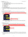
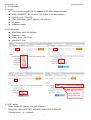
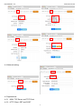
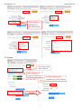
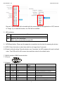
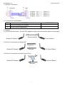
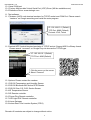
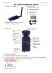
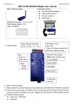
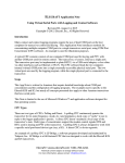
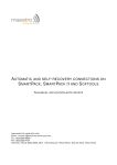
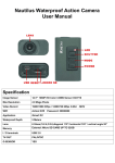
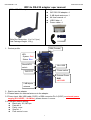
User Manual V1.0 Date: 2015.01.05 WiFi to RS-232 adapter user manual Package Contents: WiFi RS-232 adapter x 1 2 dBi dipole antenna x 1 A4 User manual x 1 USB Cable x 1 Power cable x 1 WiFi to RS-232 adapter White Box Dimension: 11 x 6 x 5 (cm) Total Package Weight: 126 g DB9 (Female) 1. Product profile: LED: System: Red Status: Blue Reset/WPS switch Mini USB Power switch DCE/DTE External Power GND +4.5~24V 2 dBi dipole antenna 2. Start to use the adapter 2.1 Please fasten the external antenna to the adapter. 2.2 Power input: Mini USB cable (5VDC) or DB9 connector Pin 9 (5VDC) or external power supply (4.8~24VDC, 1.0 A Max.), please choose 1 source. 2.3 COM port default setting: Baud rate: 115,200 bps Data bit: 8 Parity: none Stop bit: 1 Flow control: none 1 User Manual V1.0 Date: 2015.01.05 2.4 Network default setting: Simple AP with DHCP server SSID: Serial2WiFi_ab_cd (“ab” and “cd” is the last 4 code of Mac address) Security(WPA2): 12345678 IP: 192.168.10.1 Socket port: 8080 Channel: 6 Log in ID: admin Log in password: admin 2.5 DCE/DTE switch: DCE side. The switch will swap TX,RX,CTS,RTS of the COM port. Generally, DCE side for PC or NB setup. The user will test and switch to the correct side for the remote device. 3. DB9 Pin9 Power Input or Output: 3.1 External Power input or DB9 Pin 9 Power input: The two DIP switches toward N/A side by default. Please do not switch any DIP switch toward the 5V side when the power switch is in the “External/Pin9 In” side. Power input or DB9 Pin9 Remark: The power cable is used for the external power input which support larger range of voltage, 4.5~24VDC. 3.2 DB9 Pin 9 Power output: The DB9 Pin9 will power the external device by 5VDC via DB9 Pin9 when the power input comes from USB only. Please choose the USB adapter which will power larger than 1000mAh and do not power the external device which will consume exceed 100 mAh. Power input 3.3 The RS-232 temperature/humidity sensor, active RFID reader or other sensors will be powered by the DB9 pin9 directly without extra power supply. If you need the options, please contact the suppliers. 2 User Manual V1.0 Date: 2015.01.05 4. Configuration: 4.1 Log in: Connect with the WiFi RS-232 adapter by PC,NB or Mobile terminal SSID: Serial2WiFi_ab_cd (abcd: Last 4 code of the Mac address) Security code: 12345678 Execute browser, type IP address: 192.168.10.1 ID: admin Password: admin 4.2 Serial setting: Baud Rate: 9600~921600 bps Data Bits: 8 only Parity: None, Odd, Even Stop Bits: 1 only Please type the none-standard baud rate here 4.3 WiFi setting: Mode: Simple AP, Station, Dual (AP & Station) Encryption: Open, WPA TKIP, WPA AES, WPA2 TKIP, WPS2 AES Channel: auto,1~11, 6 (default) 3 User Manual V1.0 Date: 2015.01.05 4.4 Network setting: 4.5 Applications: 4.5.1 M2M: TCP Server and TCP Client 4.5.2 HTTP Client: GET and POST 4 User Manual V1.0 Date: 2015.01.05 The function is available on RS-485 adapter 4.6 System: F/W version and Mac address Mac address will output to serial port The I/O function is not available for serial adapter Enable 5 User Manual V1.0 Date: 2015.01.05 Remark: The NTP data will be bundled with the sensor data for the application of IOT, Internet of Things. If you need the function, the F/W will be modified. 5. LED indication: LED Status Red Indicates system ready Blue Solid On: WiFi connected Flash: data is transmitted through WiFi 6. WPS/Reset button: Please put the paperclip or small pin into the hole for pressing the button. 6.1 WPS: Press the button in short time which is not longer than 3 seconds. 6.2 Reset to default setting: Press the button over 5 seconds, the WiFi adapter will reset to default value. The LEDs will be off for some time and then reboot to the default value. 7. RS232 Interface: DB9 Female with Nut 7.1 Pin-out: 7.2 Signals: Pin 1 CD Input 2 TxD Output DCE Direction Output Input 3 RxD Input Output Received data Input Output Contact manufacturer to set this N/A N/A Signal ground Contact manufacturer to set this 4 5 Signal DSR GND DTE Direction Description Not connected Transmitted data 6 DTR Output Input 7 CTS Input Output Clear to send 8 RTS Output Request to send (Default) 9 Vcc Input Input Input External Power supply (Remark 1) 6 User Manual V1.0 Date: 2015.01.05 7.3 DSR/DTR Connection: 8. Command set: Not Available ITEM FUNCATION 1 Inquire the setting of the adapter 2 Set the COM port parameters COMMAND 9. Network: 9.1 One to one connection: The two WiFi adapters will be connected directly without access point. Connect directly Simple AP (Default) 1 Client (Station) 9.2 One to 5 connection via Simple AP Broadcast Simple AP (Default) Uni-cast 5 Clients (Station) 9.3 One to 5 connection via other Access Point: Broadcast Simple AP (Default) 5 Clients (Station) Uni-cast 7 User Manual V1.0 Date: 2015.01.05 10. Virtual COM port 10.1 Factory Mac bundled Virtual Serial Port (VSP) Driver (Will be available soon) 10.2 Reference Driver: www.eterlogic.com 11. Test software: 11.1 Teraterm: ASCII code terminal emulator for TCP/IP socket and COM Port. Please search “teraterm” on Google searching and install the main program. IP: 192.168.10.1 (Default) TCP Port: 8080 (Default) Protocol: IPV4, Telnet 11.2 Android APP: Android terminal emulator of TCP/IP socket. Support ASCII or Binary format. Please search “uconnect” on Google Play site choose the TCP/IP type. IP: 192.168.10.1 (Default) TCP Port: 8080 (Default) Click the menu on the corner Select “Connect” 12. Options: Please contact the vendors. 12.1 RS-232 Temperature and Humidity Sensor 12.2 RS-232 Bluetooth BLE Active RFID Reader 12.3 RS-232 Gas, CO, CO2, Smoke Sensor 12.4 IR Temperature Sensor 12.5 IR Remote controller 12.6 Power Plug Remote controller 12.7 LED Light DAC Remote controller 12.8 Home Gateway 12.9 Indoor Real Time Location System (RTLS) Remark: All contents are subject to change without notice. 8