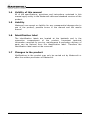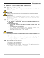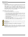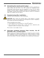
1
USERS- AND INSTALLATION MANUAL Mass Sine 24/5000 230V AC Mass Sine 24/4000 117V AC Inverter MASTERVOLT B.V. Snijdersbergweg 93 1105 AN Amsterdam The Netherlands ENGLISH: NEDERLANDS: DEUTSCH: FRANÇAIS: PAGE 1 PAGINA 25 SEITE 49 PAGE 73 Tel.: +31 20 3422100 Fax.: +31 20 6971006 e-mail: [email protected] WEB-site: www.mastervolt.com Language : English Version : V1.1-050209 2 February 2005 / Mass Sine 5000 / EN CONTENTS V1.1 February 2005 1 GENERAL INFORMATION ................................................................ 5 1.1 Use of this manual .......................................................................5 1.2 Warranty specifications ................................................................5 1.3 Quality .......................................................................................5 1.4 Validity of this manual..................................................................6 1.5 Liability ......................................................................................6 1.6 Identification label .......................................................................6 1.7 Changes to the product ................................................................6 2 SAFETY GUIDELINES AND WARNINGS............................................ 7 2.1 Warnings and symbols .................................................................7 2.2 Use for intended purpose ..............................................................7 2.3 Organizational measures ..............................................................7 2.4 Installation, maintenance and repair ..............................................8 2.5 Warning of special dangers ...........................................................8 2.6 Warning regarding life support applications .....................................8 3 OPERATION .................................................................................... 9 3.1 Introduction................................................................................9 3.2 Switching on and off ....................................................................9 3.3 Indicator lights ............................................................................9 3.4 On the remote control ................................................................ 11 3.5 Maintenance ............................................................................. 11 4 INSTALLATION ............................................................................. 12 4.1 Environment ............................................................................. 12 4.2 Wiring...................................................................................... 12 4.3 Mounting of the cabinet .............................................................. 12 4.4 Connecting ............................................................................... 13 4.4.1 Opening the front panel ........................................................ 13 4.4.2 Connecting AC wiring & earth wiring ....................................... 13 4.4.3 DC wiring............................................................................ 14 4.4.4 Battery cable connections...................................................... 14 4.5 Connecting the remote control panel ............................................ 15 4.6 Commissioning after installation .................................................. 15 4.7 Automatic switching between Mass inverter, the AC generator and / or shore power.................................................................. 15 5 TROUBLE SHOOTING .................................................................... 16 6 TECHNICAL DATA ......................................................................... 17 6.1 230V Inverters .......................................................................... 17 6.2 117V Inverters .......................................................................... 18 7 DIMENSIONS ................................................................................ 19 8 INSTALLATION DRAWINGS .......................................................... 20 February 2005 / Mass Sine 5000 / EN 3 4 February 2005 / Mass Sine 5000 / EN 1 1.1 GENERAL INFORMATION Use of this manual This manual serves as a guideline for the safe and effective operation, maintenance and possible correction of minor malfunctions of the Mastervolt Mass Sine. This manual is valid for the following models: 1. 2. 3. 4. Mass Mass Mass Mass Sine Sine Sine Sine 24/5000 24/5000 24/4000 24/4000 230V 230V 117V 117V AC-50Hz, AC-60Hz, AC-60Hz, AC-50Hz, art. art. art. art. No No No No 24095100. 24195100. 25024000. 25124000. It is therefore obligatory that every person who works on or with the Mass Sine must be completely familiar with the contents of this manual, and that he/she carefully follows the instructions contained herein. Installation of, and work on the Mass Sine, may once be carried out by qualified, authorized and trained personal, consistent with the locally applicable standards and taking into consideration the safety guidelines and measures (chapter 2 of this manual). Save this manual at a secure place! 1.2 Warranty specifications Mastervolt guarantees that this product has been built according to the legally applicable standards and specifications. Should work take place, which is not in accordance with the guidelines, instructions and specifications contained in this users manual, then damage may occur and/or the unit may not fulfil its specifications. All of these matters may mean that the guarantee may become invalid. The warranty is limited to the costs of repair and/or replacement of the product. Costs for installation labour or shipping of the defective parts are not covered by this warranty. 1.3 Quality During their production and prior to their delivery, all of our units are exhaustively tested and inspected. The warranty period is two years after date of purchase. February 2005 / Mass Sine 5000 / EN 5 1.4 Validity of this manual All of the specifications, provisions and instructions contained in this manual apply solely to the Mastervolt-delivered standard versions of the product. 1.5 Liability Mastervolt can accept no liability for any consequential damage due to use of the product, possible errors in the manual and the results thereof. 1.6 Identification label The identification labels are located at the backside and in the connection compartment of the product. Important technical information required for service, maintenance & secondary delivery of parts can be derived from the identification label. Therefore the identification label must not be removed! 1.7 Changes to the product Modifications to the product may only be carried out by Mastervolt or after the written permission of Mastervolt. 6 February 2005 / Mass Sine 5000 / EN 2 2.1 SAFETY GUIDELINES AND WARNINGS Warnings and symbols Safety instructions and warnings are marked in this manual by the following symbols: CAUTION! Special data, restrictions and rules with regard to preventing damage. WARNING! A WARNING refers to possible injury to the user or significant material damage to the product if the installer / user does not (carefully) follow the procedures. 2.2 Use for intended purpose • • The product is constructed as per the applicable safety-technical guidelines. Use the product only: − with a fuse, protecting the wiring between product intput and battery; − in a technical correct condition; − in a closed, well-ventilated room, protected against rain, moisture, dust and non condensing circumstances; − observing the instructions in this manual. WARNING! Never use the product in situations where there is danger of gas or dust explosion! • 2.3 Use other than as mentioned above is not considered to be consistent with the intended purpose. Mastervolt is not liable for any damage resulting from unintended use. Organizational measures The installer / user must always: • have access to this manual; • be familiar with the contents of this manual. This applies particularly to Chapter 2, Safety Guidelines & Warning. February 2005 / Mass Sine 5000 / EN 7 2.4 Installation, maintenance and repair If the product is switched off during maintenance and/or repair activities, it should be secured against unexpected and unintentional switching on: • switch off the connection with the batteries and remove the battery fuse of the product; • be sure that third parties cannot reverse the measures taken. 2.5 Warning of special dangers • • • • • • • 2.6 Connect the earth of the inverter output to the central ground and use an RCCB switch in the inverter output. Secure the DC wiring with a fuse, according to the guidelines in this user manual. Connection and protection of your electrical system must be done in accordance with local standards. Do not work on the product or the electrical installation if it is connected to a power source. Only allow changes in your electrical system to be carried out by qualified electricians. Check the wiring at least once a year. Defects such as loose connections, heat damaged cables etc. must be corrected immediately. Not only the batteries, but the product as well can become a projectile if your transport is involved in an accident! Ensure adequate and secure mounting and always use suitable handling equipment for transportation. Except for the connection compartment the cabinet of the product must not be opened. There are no serviceable parts inside the cabinet. Only qualified, authorized and trained electrician installers are authorized to open the connection compartment. Warning regarding life support applications Mastervolt products are not sold for applications in any medical equipment intended for use as a component of any life support system unless a specific written agreement pertaining to such intended use is executed between the product manufacturer and Mastervolt. Such agreement will require the equipment manufacturer either to contract for additional reliability testing of the Mastervolt parts and/or to commit to undertake such testing as a part of the manufacturing process. In addition such manufacturer must agree to indemnify Mastervolt from any claims arising from the use of Mastervolt parts in the life support equipment. 8 February 2005 / Mass Sine 5000 / EN 3 3.1 OPERATION Introduction The Mass SINE inverter is a fully automatic high efficiency inverter developed and produced by Mastervolt Amsterdam. The MASS SINE inverter is part of a series of advanced quality battery chargers and inverters supplied by Mastervolt all over the world. The MASS SINE inverter converts DC voltage to 230VAC~50/60Hz or 117VAC~60/50Hz. The AC output voltage has a sinusoidal waveform for reliable and trouble free operation of connected equipment. The inverter is protected against overload, short circuit and over temperature. In case of overload, the inverter will reduce its output power. 3.2 Switching on and off Switching on: Put the on/off/remote switch on the front of the inverter on "on". The green lamp “inverter on” lights up, and the inverter will start. If you use a remote control panel, put the on/off/remote switch to “remote”, and put the on/off switch on the remote control panel to “on”. Switching off: Put the on/off/remote switch on the front of the inverter on "off". The inverter stops and all the lights that are on, go off. CAUTION! Switching off the inverter with the switch on the front or via the remote does not break the connection to the mains or the batteries. 3.3 Indicator lights The functions of the indicator lights on the front are: LED Inverter on Overload Meaning Inverter is switched on Inverter is overloaded February 2005 / Mass Sine 5000 / EN Short description The green light shows when the inverter is switched on. Glows if the inverter is overloaded. When the inverter is overloaded, the power limit reduces the output voltage. Depending on the load, the inverter will shut down after a short period. 9 LED Overload + on slow Meaning Overload in wait state Overload + on fast Inverter is switched off Low battery Battery voltage is too low Temperature 10 Inverter is overheated Short description When the inverter is in a state of overload for a long period of time the inverter will switch off and the overload + on indicators will flash slowly. This takes approx. 20 seconds after which the inverter automatically will restart. This so called wait state gives the inverter time to recover from any heavy surge loads and the battery time to recover in case of an empty battery. When the inverter is switched of 10 times with intervals no more than 30 seconds apart the inverter will switch off permanently and the “overload” and ON indicators will flash fast. To switch the inverter on again, you must manually switch the inverter off and on. When the output is short circuited, the inverter will go into overload. The “overload” and ON indicators will flash slowly. The inverter will try to start up ten times. If the short circuit is not removed, the inverter will switch off permanently. Remove the short circuit and reset the inverter by switching it off and on. The inverter is switched off if the battery voltage is too low (see table below). If the voltage rises above the values given below, the inverter restarts automatically. Switching off voltage: 19V Switching on voltage: 22V The inverter switches off in high ambient temperatures and / or sustained overload. After cooling down, the inverter restarts automatically. February 2005 / Mass Sine 5000 / EN 3.4 On the remote control If you use a remote control panel, put the on/off switch to “remote”, and put the on/off switch on the remote control panel to ON. The meaning of the illuminated LED’s is: • • inverter on: inverter is switched on failure: inverter is overloaded, overheated or battery voltage is too low If the failure lamp is lit you can check the nature of the failure on the inverter front. 3.5 Maintenance For reliable and optimum function examine your electrical installation on a regular base, at least once a year. Defects such as loose connections, burnt wiring etc. must be corrected immediately. Keep the inverter dry, clean and dust-free, in order to ensure good heat discharge. If necessary, use a soft clean cloth to clean the cabinet. Never use any liquids, acids and/or scourers. February 2005 / Mass Sine 5000 / EN 11 4 INSTALLATION During installation and commissioning of the MASS inverter, the Safety Guidelines and Measures are applicable at all times. See chapter 2 of this manual. 4.1 Environment Install the MASS inverter in a dry, well ventilated, dust free situation. Locate the inverter as close as possible to the DC distribution in order to keep the battery cables short. Do not locate the inverter in the same compartment as the batteries. The heat of the inverter is discharged by a fan with a variable speed, from the top and side of the cabinet to the bottom of the cabinet. When fitting the inverter be sure that: • the air flow is not obstructed; • the inverter is mounted vertically; • no water and / or dust can enter the cabinet. WARNING! Never use the inverter in locations where there is gas or explosion danger! 4.2 Wiring The routing of the wires has influence on the EMC behavior of the system in which the inverter is a component. This is caused by the fact that wires are excellent receivers and transmitters of radio frequency electro magnetic interference. Most problems originate from mutual interference between wires and cables. Therefore you should separate AC and DC cables and lay the cables in metal cable trunk and connect this trunk to ground. The metal of the trunk offers a low resistance to interference currents, so that these currents run via the trunk to ground. A compromise would be to lay the cables besides a metal strip. If this solution is also not workable then make a cable loom. 4.3 Mounting of the cabinet Use suitable screws and dowels to fix the MASS inverter to the wall. To mount the MASS inverter follow the described instructions: 1. Determine the mounting points (see Figure 7-1). 2. Drill mounting holes for the cabinet. 3. Mount the MASS inverter with four screws or bolts (M6) to the wall. 4. Fasten all screws or bolts securely. 12 February 2005 / Mass Sine 5000 / EN 4.4 Connecting The Mastervolt Service Centres have all accessories available, e.g. battery terminals and supply cables in all sizes. Refer to the installation drawings during installation (chapter 8) WARNING! Before beginning to connect the wiring, make the AC and DC distribution voltage-free. 4.4.1 Opening the front panel Loosen the two Philips screws that secure the front cover plate for two turns. Pull the grey front panel away from the cabinet (downwards). The terminals and cable glands are now accessible. 4.4.2 Connecting AC wiring & earth wiring The inverter is protected against overload and short circuit, so it is not necessary to install a fuse in the output of the inverter. CAUTION! For safe installation it is necessary to: • connect the earth (PE) and neutral (N) of the inverter output to the central ground; • insert a RCCB (earth leakage) switch of 30mA in the inverter output. Please acquaint yourself with the local regulations on this issue! WARNING! Check whether the voltage from the inverter is the same as the connected equipment. WARNING! The earth wire offers protection only if the inverter cabinet is connected to the earth. Connect the inverter's earth terminal (at the right hand side of the AC terminal block) to the hull or chassis via the earth stud. To connect the Mass SINE inverter to the mains: 1. Switch the on/off/remote switch to 'off'. The L1, N and PE terminals are situated on the left hand side inside the cabinet. 2. Connect the AC on-board system brown phase 4mm/AWG 11 wire to terminal L1, the blue neutral wire to terminal N and the green/yellow earth wire to terminal PE. February 2005 / Mass Sine 5000 / EN 13 4.4.3 DC wiring Keep the cable length as short as possible, this will keep the system efficiency as high as possible. The recommended minimum size of the battery cables is 4 x 50mm/AWG 0 (see Figure 8-2) or 2 x 70mm/AWG 2/0 with two jumpers (included, see Figure 8-3). The recommended length is a maximum of 3 meters. When longer cables are required, use thicker cables. When possible, use coloured (red and black) battery cables. If this is not possible, mark the cables with red and black isolation tape or heat shrink sleeve. 4.4.4 Battery cable connections To connect the Mass SINE inverter to the batteries: 1. Pull the battery cables through the glands at the bottom side of the inverter. Keep the cable connection between batteries and inverter as short as possible (maximum 3 meters). 2. Connect the black negative battery cable to the negative connection bolt (right) and the red positive battery cable to the positive bolt (left) of the inverter. 3. Cut the cables to the right length and fix, if necessary; connect cable clamps to both ends. 4. Connect the negative cable to the negative battery pole and the positive cable via the inverter fuse to the positive red pole. CAUTION! Pull the battery cables through the glands before you install the cable clamps. CAUTION! Reversing positive and negative will cause major damage to the inverter. This damage is not covered by the guarantee. CAUTION! Too-thin cables and/or loose connections can cause dangerous overheating of the cables and/or terminals. Therefore tighten all connections well, in order to limit transition resistance as much as possible. Use DC cables of the correct size. 14 February 2005 / Mass Sine 5000 / EN 4.5 Connecting the remote control panel The remote control panel C4-RI for the MASS inverter comprises an off/on switch and two LED’s. The LED 'inverter on' indicates proper functioning of the inverter and the availability of 230/117V AC output voltage. The LED 'failure' indicates overload, over temperature or too low voltage. Connect the remote control panel by means of a telephone cable (not supplied with the panel). 4.6 Commissioning after installation Carefully check the polarity of the connections. CAUTION! Only insert the inverter fuse if the polarity is correct. Switching on with incorrect polarity will damage the inverter irreparably. The inverter fuse cannot prevent this. If the connections are correct: • check whether the on/off switch is in the OFF position; • when inserting the inverter fuse, a spark will occur, caused by the capacitor used in the inverter. This is normal. The inverter is now ready for use. 4.7 Automatic switching between Mass inverter, the AC generator and / or shore power Please contact your Mastervolt supplier if you intend to use the inverter with a generator or shore power connection. Hand switched or simple relay switching systems could damage your inverter, because of the lack off time delay. This kind of damage is not covered by the warranty. February 2005 / Mass Sine 5000 / EN 15 5 TROUBLE SHOOTING Malfunction No output voltage and no indication lights No output voltage, LED low batt is lit. No output voltage and LED temp is lit. Inverter goes on and off, LED on and LED low bat are blinking in turn. Possible cause High output voltage DC fuse blown. Switch set to remote, but no remote present. Flat battery. The inverter has been overloaded. Flat battery. Cables too thin. Connections are corroded or bad. Inverter goes on and off, LED on and overload blink in turns one time per second, ventilator is running at full speed. Inverter goes on and off, LED on and overload blink in turns five times per second, ventilator is running at full speed. Inverter is overloaded. Inverter has been switched off ten times as a result of an overload situation or a short circuit. What to do Check battery voltage and switch charger off. (LED’s off) Replace the fuse. Put switch at on. Charge the batteries, the inverter will switch on if the battery voltage is above 22V. Reduce the load and let the inverter cool down. Disconnect load and charge batteries. Replace with cables of correct diameter. Tighten the connections. If the cables are burned, replace them. Reduce the load on the inverter. Reduce the load or the short circuit. Reset the inverter manually by means of the on/off switch. If you cannot correct a problem with the aid of the malfunction table, contact your Mastervolt Service Centre or Mastervolt Amsterdam for an extended service list, telephone: INT+ 31-20-3422100. 16 February 2005 / Mass Sine 5000 / EN 6 TECHNICAL DATA 6.1 230V Inverters GENERAL Function apparatus supplying of AC equipment Models 24/5000 Manufacturer Mastervolt, Amsterdam INPUT Battery voltage nominal 24V Switch off voltage low 19V Switch on voltage low 22V Switch off voltage high 32V Switch on voltage high 30V Maximal ripple 5% Current (nominal load) 240A No load 300mA/7W Fuse 2X160A or 1x250A slow blow DC Cable 4x50mm²/AWG 0 or 2x70 mm²/AWG 2/0 with two jumpers (included). OUTPUT Output voltage 230VAC, ±5% Output waveform true sine wave Frequency 50Hz, ±0.01% (60Hz model orderable) Nominal power Tamb=40°C 4000W Half hour power Tamb=25°C 5000W Peak power 9000W Cos phi All power factors allowed. Efficiency nominal 90% CLIMATE Nominal temperature -20 till 40°C / -4°F till 104°F Cooling Cooling partial conventional / forced with temperature regulated fan Humidity < 95% relative humidity, non condensing. ENCLOSURE Dimensions (hxwxd) 470x315x254 mm / 18.5x12.4x10.0 inch Weight 25 kg / 55 lbs Protection degree IP 23 STANDARDS Emission EN 50081-1:1992 Immunity EN 50082-1:1997 Safety EN 60950:2000 February 2005 / Mass Sine 5000 / EN 17 6.2 117V Inverters GENERAL Function apparatus supplying of AC equipment Models 24/4000 Manufacturer Mastervolt, Amsterdam INPUT Battery voltage nominal 24V Switch off voltage low 19V Switch on voltage low 22V Switch off voltage high 32V Switch on voltage high 30V Maximal ripple 5% Current (nominal load) 200A No load 300mA/7W Fuse 2x160A or 1x250A slow blow DC Cable 4x50mm²/AWG 0 or 2x70 mm²/AWG 2/0 with two jumpers (included). OUTPUT Output voltage 117VAC, ±5% Output waveform true sine wave Frequency 60Hz, ±0.01% (50Hz model orderable) Nominal power Tamb=40°C 3500W Half hour power Tamb=25°C 4000W Peak power 7000W Cos phi All power factors allowed. Efficiency nominal 90% CLIMATE Nominal temperature -20 till 40°C / -4°F till 104°F Cooling Cooling partial conventional / forced with temperature regulated fan Humidity < 95% relative humidity, non condensing ENCLOSURE Dimensions (hxwxd) 470x315x254 mm / 18.5x12.4x10.0 inch Weight 25 kg / 55 lbs Protection degree IP 23 STANDARDS 18 Emission EN 50081-1:1992 Immunity EN 50082-1:1997 Safety EN 60950:2000 February 2005 / Mass Sine 5000 / EN 7 DIMENSIONS 315 10.5 294 254 11 21 405.5 470 241 Figure 7-1: Dimensions inverter. February 2005 / Mass Sine 5000 / EN 19 8 INSTALLATION DRAWINGS ON OFF 123456 AC Output DC input DC Fuse L1 N PE BATTERY + BATTERY _+ _ Figure 8-1: Installation of the Mass SINE. 20 February 2005 / Mass Sine 5000 / EN + – + – Figure 8-2: Option 1 – 4 x 50mm² / AWG0 – + Figure 8-3: Option 2 – 2 x 70mm² / AWG2/0 February 2005 / Mass Sine 5000 / EN 21 22 February 2005 / Mass Sine 5000 / EN CE DECLARATION OF CONFORMITY Manufacturer: Mastervolt Address: Snijdersbergweg 93 1105 AN Amsterdam The Netherlands Herewith declares that: Product: 1. 2. 3. 4. Mass Mass Mass Mass Sine Sine Sine Sine 24/5000 24/5000 24/4000 24/4000 230V 230V 117V 117V AC-50Hz, AC-60Hz, AC-60Hz, AC-50Hz, art. art. art. art. No No No No 24095100. 24195100. 25024000. 25124000. Is in conformity with the provision of the EC, EMC directive 89/336/EEC and amendments 92/31/EEC, 93/68/EEC The following harmonized standards have been applied: Generic emission standard EN 50081-1:1992, Generic immunity standard EN 50082-1:1997, And the safety directive 73/23/EEC and amendment 93/68/EEC, with the following standard: Low voltage standard EN 60950:2000, Amsterdam, R.J. ter Heide, Managing Director MASTERVOLT February 2005 / Mass Sine 5000 / EN 23 Snijdersbergweg 93, 1105 AN Amsterdam, The Netherlands Tel : + 31-20-3422100 Fax : + 31-20-6971006 24 e-mail : [email protected] February 2005 / Mass Sine 5000 / EN