1
!
"#
$
!
"
!"!#
!
!
!
"
!
$!
#
%!
!
!!""##!#!
!
" #$# #
!" !"
!" AXIOMTEK is a trademark of AXIOMTEK Co., Ltd.
MS-DOS, and Windows !95 are trademarks of Microsoft
Corporation.
AWARD is a trademark of Award Software, Inc.
IBM, PC/AT, PS/2, VGA are trademarks of International
Business Machines Corporation.
Intel and Pentium are trademarks of Intel Corporation.
C&T is a trademark of Chips and Technologies, Inc.
SST is a trademark of Silicon Storage Technology, Inc.
Other brand names and trademarks are the properties and
registered brands of their respective owners.
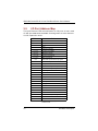
Chapter 1 Introduction
Chapter 2 Jumpers and Connectors
! "
# $
2.2.1
2.2.2
2.2.3
2.2.4
2.2.5
2.2.6
2.2.7
2.2.8
2.2.9
%
CPU Bus Clock: JP8 ...........................................7
DiskOnChip Memory Segment: JP2................8
COM1~COM4 Mode: JP11, JP14, JP15, JP16...8
COM4 Mode Select: JP10, JP12, JP13 .............8
Flat Panel Power Selection (V DDM of CN11 and
CN6): JP9 ...........................................................9
Watchdog Trigger Mode Setting: JP7..............9
CMOS Clear Jumper: JP4 .................................9
Audio Line Out/Speaker Out Jumper: JP18.....9
Keyboard Wakeup Function Setting: JP3 ...... 10
& '
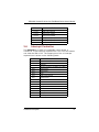
Chapter 3 Hardware Description
%
%
%%
%
%"
%-
%$
%0
( &)& *+ ( *,+)
( *& %
*./*& .* "
3.8.1
3.8.2
3.8.3
3.8.4
Flat Panel/CRT Interface Controller............... 15
Features ........................................................... 15
VGA/Flat Panel Connectors ........................... 16
Flat Panel Connector Pin Description ........... 17
%1 .& 0
%' ))* 0
% )* 1
Table of Contents
3.11.1 Serial Ports IRQ Selection ................................ 19
3.11.2 Serial Ports +5V and +12V Power Selection .. 19
Table of Contents
% .*,+ '
3.12.1 Digital I/O Software Programming ................ 21
%%
%
%"
%-
%$
%0
%1
%'
2&&(+2
( 34),(& & /5& %
&)& %
)&,'& )&*,*
& "
)
+5& 0
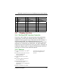
Chapter 4 Display Drivers
6% %
67%" %
%
+, %"
4.1.1
4.1.2
4.1.3
4.1.4
4.2.1
4.3.1
4.3.2
4.3.3
Driver Installation - DOS Setup ....................... 32
Changing Display Drivers from DOS .............. 33
Changing Display Drivers from Windows....... 33
Changing Color Schemes .............................. 33
Driver Installation ............................................ 34
Driver Installation ............................................ 35
WIN-OS/2 ......................................................... 36
Driver Diskette Copy ....................................... 37
Chapter 5 Ethernet
"
"
"%
* %1
%1
.8 %1
Chapter 6 Audio Device
-
-
-%
* .8 Table of Contents
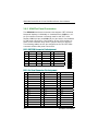
Chapter 7 Award BIOS Utility
$
$
$%
$
$"
$-
/ %
&3 9! 5(( "
&(+( -
*+( "'
$$
$0
$1
$'
$
$
$%
$
$"
$-
$$
&5( "-
)( "1
)),)&*& -%
*+. -"
. --
*)5 -$
8,) $'
*./!..
. $
8:/ $
/ 658 $"
);+ $"
7.6.1
Onboard VGA Functions ................................ 55
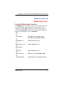
Appendix A
Watchdog Timer
565 $$
Appendix B
AUDIO/NET Driver
Installation under
Win95/98
Table of Contents
SBC8360 Socket370 All-in-One Petit Board Series User’s Manual
#$%
%
&
'()*+,
-
-./.0
#
%
1
$2
$234567#&
,8
9
:(+;'/(/"+;'/(/$9//$9<.=>.4$"/4
$2,%'
+
+
%#
Introduction
"
SBC8360 Socket370 All-in-One Petit Board Series User’s Manual
8'
%
%&%
'(
#" CPU
!"Intel Celeron
!"Intel Pentium III
#" System Chipset: Intel 440BX Core Logic Controller
#" Processor Socket:
ZIF Socket370
#" Bus Clock: 66/100 MHz
#" BIOS
!"Award BIOS, Y2K compliant
!"2Mbit Flash ROM, DMI, Plug and Play
#" System Memory
!"One 168-pin DIMM
!"Maximum SDRAM of up to 256MB (buffered)/128MB
(unbuffered)
#" L2 Cache: Integrated in CPU
#" Onboard IDE
!"2 channels up to 4 devices (IDE1 x 44-pin, IDE2 x 40-pin)
!"PIO Mode 0-4, DMA Mode 0-2 and Ultra DMA/33
!"LS-120 & ZIP Bootable
#" Onboard Multi-I/O
!"One floppy port (box header) supporting up to two
devices (LS-120 & ZIP Bootable)
!"One SPP/EPP/ECP parallel port (box header), LS-120
supported
/
Introduction
SBC8360 Socket370 All-in-One Petit Board Series User’s Manual
!"Four 16550 UARTs compatible serial ports with +5V/+12V
power output in pin 1 or pin 9 via jumper setting (TTL
level reserved in COM2):
#"3 x RS-232 (box header)
#"1x RS-232/422/485 box header and selectable via
jumper setting
#"1 x IrDA (box header) for wireless communcation
#" Real Time Clock: Dallas /ST12887 or latest product
#" Watchdog Timer
!"System reset or Non-Maskable Interrupt software
programmable Time interval and jumper selectable
!"64 levels, 0.5~8 / 5~80 / 50~800 / 100~1600 seconds
#" Ethernet
!"Realtek 8139 PCI Bus 10/100M Base-T
!"Wake-On-LAN (via ATX power)
!"RJ-45 interface (box header) equipped
#" Digital I/O: 4-channel TTL/DTL compatible input and
output
#" USB Interface: 2 USB ports with fuse protection and
complies with USB Spec. Rev. 1.1A
#" Power Management: ACPI (Advanced Configuration and
Power Interface)
#" Hardware Monitoring
!"Winbond W83781D
!"Monitoring for CPU/system temperatures, system voltage,
and chassis/fan speeds
#" Onboard Display
!"AGP interface controller with integrated 2MB SDRAM
!"VGA chipset: C&T 69000 AGP-1x supporting CRT/LCD
displays
!"Supports up to 1280 x 1024 256-color resolution on noninterlaced CRT monitors, and 1024 x 768 16 bit-color on
LCD panel monitors
#" DiskOnChip : supports M-Systems DiskOnChip
#" Expansion Slots:
!"One 16 Bit PC/104 connector
!"One EISA slot for PCI/ISA expansion
Introduction
(
SBC8360 Socket370 All-in-One Petit Board Series User’s Manual
#" Onboard Audio
!"ESS Solo-1 1938 32-bit PCI 2.1 AudioDrive controller
!"High quality ESFM Music Synthesizer
!"Dynamic range (SNR) over 80dB
!"Integraed Spatializer 3D audio effects processor
!"32-bit Sound Blaster and Sound Blaster Pro compatible
!"16-bit stereo ADC and DAC
!"PC97/PC98 and WHQL specifications
!"Full-duplex operation for simultaneous record and
playback
!"Internal MIC-in, Line-in, Speaker/Line-out interface
reserved
#" Other Features
!"Win 95/98/2000 Software-off
#" Form Factor: Current 5.25” form factor
#" Dimensions: 203.20 x 146.05 mm 2
NOTE:
%&)
Specifications are subject to change without
notice.
#''
#"Ethernet Utility
#"Flat panel/CRT Drivers
#"Audio Drivers
9
Introduction
SBC8360 Socket370 All-in-One Petit BoardSeries User’s Manual
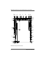
)&%
*#
+,-
.
1
'#<(?*
7
Jumpers and Connectors
.
SBC8360 Socket370 All-in-One Petit Board Series User’s Manual
'#<(?*@+0%
?
Jumpers and Connectors
SBC8360 Socket370 All-in-One Petit Board Series User’s Manual
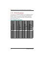
)&)
/#$'
-
1
1
1
Jumper
JP1
JP2
JP3
JP4
JP7
JP8
JP9
JP10
JP11
JP12
JP13
JP14
JP15
JP16
JP18
Default Setting
Reserved
Jumper Setting
Open
DiskOnChip Memory Segment
Setting: D0000 - D1FFF
Keyboard Wakeup Function Setting:
Disabled
CMOS Clear Setting: Normal
Watchdog Timer Mode Setting: NMI
CPU Bus Clock Settings: 66MHz
Flat Panel Power Selection: 5V
COM4 Settings: RS-232
COM3 Mode: Pin 1=DCD, Pin 8=RI
COM4 Settings: RS-232
COM4 Settings: RS-232
COM2 Mode: Pin 1=DCD, Pin 8=RI
COM4 Mode: Pin 1=DCD, Pin 8=RI
COM1 Mode: Pin 1=DCD, Pin 8=RI
Audio Line Out/Speaker Out
Setting: Line Out
Short 1-2, 3-4
Short 1-2
Open
Short
Short
Short
Short
Short
Short
Short
Short
Short
Short
1-2
1-2,
1-2
3-5,
3-5,
3-5,
1-2
3-5,
3-5,
3-5,
3-4
4-6
4-6
4-6
4-6
4-6
4-6
Short 1-3, 2-4
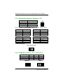
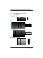
Options
Setting
66MHz
Short 1-2, 3-4 (default)
Short 3-4
100MHz
Jumpers and Connectors
JP8
)
SBC8360 Socket370 All-in-One Petit Board Series User’s Manual
Options
D0000
D2000
D4000
D6000
–
–
–
–
Settings
D1FFF
D3FFF
D5FFF
D7FFF
JP2
Short 1-2, 3-4 (default)
Short 1-2
Short 3-4
All Open
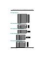
!"#$"$%$&
COM1
JP16
Pin 1=5V
*Pin 1=DCD
Pin 8=12V
*Pin 8=RI
Short
Short
Short
Short
1-3
3-5
2-4
4-6
Short
Short
Short
Short
1-3
3-5
2-4
4-6
COM2
JP14
Pin 1=5V
*Pin 1=DCD
Pin 8=12V
*Pin 8=RI
Short
Short
Short
Short
1-3
3-5
2-4
4-6
Short
Short
Short
Short
1-3
3-5
2-4
4-6
COM3
JP11
Pin 1=5V
*Pin 1=DCD
Pin 8=12V
*Pin 8=RI
COM4
JP15
Pin 1=5V
*Pin 1=DCD
Pin 8=12V
*Pin 8=RI
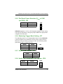
JP11/14/15/16
" "#'$$ COM4
JP10
RS-232 (default)
RS-422
RS-485
3-5, 4-6
1-3, 2-4
1-3, 2-4
JP12
JP13
3-5, 4-6
1-3, 2-4
1-3, 2-4
1-2
3-4
5-6, 7-8
JP10/12
<
JP13
Jumpers and Connectors
SBC8360 Socket370 All-in-One Petit BoardSeries User’s Manual
% ())*+, -.
)#.&/0
VDDM
JP9
Settings
5V
Short 1-2 (default)
Short 2-3
3.3V
>((4>.4
1
& 1)#2#3
#%,
BC#%,
Options
Settings
NMI
Short 1-2 (default)
Short 2-3
Open
RESET
Disabled
JP7
3 )"
Options
Clear CMOS
Normal
Settings
Short 1-2
Open (default)
4#56)
Options
Settings
Line Out
Short 1-3, 2-4 (default)
Short 3-5, 4-6
Speaker Out
Jumpers and Connectors
JP18
A
SBC8360 Socket370 All-in-One Petit Board Series User’s Manual
0 78)#1)( JP3
Options
Settings
Disabled
Short 1-2 (default)
Short 2-3
Enabled
)&
#%,
'
&
#(
Connectors
Label
Connectors
Label
CPU and System Fan
Connector
CN1, CN7,
CN26
COM1
CN18
Power Connector 1
CN2
COM2
CN19
KeyLock/Power LED
CN3
COM3
CN20
Audio Connector
CN4
COM4
CN21
IDE Channel 1
CN5
VGA Connector
CN22
Flat Panel Connector
CN6, CN11
Printer Port Connector
CN23
Reset Connector
CN8
Digital I/O Connector
CN24
IrDA Connector
CN9
Ethernet Connector
CN25
USB Connector
CN10
Power Button
Connector
CN27
KB and PS/2 Mouse
CN12
Reserved
CN29
EISA Connector
CN13
Temperature Sensor
Connector
CN30
PC/104 8-bit Connector
CN14
HDD Active LED
JP5
PC/104 16-bit
Connector
CN15
FDD Connector
CN16
IDE Channel 2
CN17
"*
Internal Speaker
Connector
Net LED
Link LED: 1-2
Tx/Rx: 3-4
JP6
JP17
DiskOnChip Connector U13
Jumpers and Connectors
SBC8360 Socket370 All-in-One Petit Board Series User’s Manual
!
&%
"'
#
%#%,
'
#%,
,B3
2'$/ B$/*** A.$A<
C'2'
#%,
1
#%,#%,#
#%,
4
1
C
#%,
&)
#
#%,
??
"**C0-
#%,#
1
&
0
'2'
6
%
%
2'/C@&%;2C
&1
*$
"$*
#%,
"?<CC
:7CC
=+
/.?C';6C
-
"?C(/C?9C"/<C
/.?C
NOTE:
Use SDRAM modules with PC100 or PC133
specifications when running 100MHz CPU bus
speed. With 66MHz CPU, SDRAM modules with PC66,
PC100 or PC133 specifications can be used. You
have to install the Intel Celeron processor before
installing the memory modules.
Hardware Description
""
SBC8360 Socket370 All-in-One Petit Board Series User’s Manual
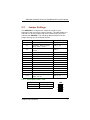
&2
0
"'
%#%,$2
"D
$2+
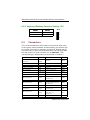
Address
Devices
000-01F
DMA controller #1
Interrupt controller #1
Timer
Keyboard controller
Real time clock, NMI
DMA page register
Interrupt controller #2
DMA controller #2
Clear math coprocessor busy signal
Reset math coprocessor
Math processor
Disable watchdog timer operation (read)
Enable watchdog timer operation (read)
Watchdog
Digital I/O
Fixed disk controller
Game port
Winbond I/O #2
Parallel port #2
Prototype card
Reserved
Parallel port #1
SDLC #2
SDLC #1
MDA video card (including LPT1)
EGA card
CGA card
020-03F
040-05F
060-06F
070-07F
080-09F
0A0-0BF
0C0-0DF
0F0
0F1
0F8-0FF
120
121
122
123
1F0-1F8
200-207
250-25F
278-27F
300-31F
360-36F
378-37F
380-38F
3A0-3AF
3B0-3BF
3C0-3CF
3D0-3DF
Continued . . . . .
"/
Hardware Description
SBC8360 Socket370 All-in-One Petit Board Series User’s Manual
Address
3F0-3F7
3F8-3FF
3E8-3EF
2F8-2FF
2E8-2EF
3F0-3FF
&3
Devices
Floppy disk controller
Serial port #1 (COM1)
Serial port #3 (COM3)
Serial port #2 (COM2)
Serial port #4 (COM4)
Winbond I/O #1
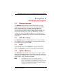
0#'
"**E%#
"?'68@+
'6%#"?
8
NMI
IRQ0
IRQ1
IRQ2
IRQ3
IRQ4
IRQ5
IRQ6
IRQ7
IRQ8
IRQ9
IRQ10
IRQ11
IRQ12
IRQ13
IRQ14
IRQ15
Hardware Description
Parity check error
System timer output
Keyboard
Interrupt rerouting from IRQ8 through IRQ15
Serial port #2
Serial port #1
Audio
Floppy disk controller
Parallel port #1
Real time clock
Ethernet
Serial port #3
Serial port #4
PS/2 Mouse
Math coprocessor
Primary IDE channel
Secondary IDE Channel
"(
SBC8360 Socket370 All-in-One Petit Board Series User’s Manual
&
0
0(
/%#
&
9&
$
?9
99&
/.&
9*
&
(.&
CN5: IDE Connector Pin Assignment
Pin
1
4
7
10
13
16
19
22
25
28
31
34
37
40
43
Description
Reset #
Data 8
Data 5
Data 11
Data 2
Data 14
GND
GND
IOR #
No connector
Interrupt
No connector
HDC CS0 #
GND
GND
Pin
2
5
8
11
14
17
20
23
26
29
32
35
38
41
44
Description
GND
Data 6
Data 10
Data 3
Data 13
Data 0
No connector
IOW #
GND
No connector
No connector
SA0
HDC CSI #
Vcc
No connector
Pin
3
6
9
12
15
18
21
24
27
30
33
36
39
42
Description
Data 7
Data 9
Data 4
Data 12
Data 1
Data 15
No connector
GND
IOCHRDY
GND-Default
SA1
SA2
HDD Active #
Vcc
CN17: 40-pin IDE Connector Pin Assignment
Pin
1
4
7
10
13
Description
Reset #
Data 8
Data 5
Data 11
Data 2
Pin
2
5
8
11
14
Description
GND
Data 6
Data 10
Data 3
Data 13
Pin
3
6
9
12
15
Description
Data
Data
Data
Data
Data
7
9
4
12
1
Continued . . . . .
"9
Hardware Description
SBC8360 Socket370 All-in-One Petit Board Series User’s Manual
Pin
16
19
22
25
28
31
34
37
40
&4
Description
Data 14
GND
GND
IOR #
No connector
Interrupt
No connector
HDC CS0 #
GND
Pin
17
20
23
26
29
32
35
38
Description
Data 0
No connector
IOW #
GND
No connector
No connector
SA0
HDC CSI #
Pin
18
21
24
27
30
33
36
39
Description
Data 15
No connector
GND
IOCHRDY
GND-Default
SA1
SA2
HDD Active #
'*
0(
())692:-)
#F?A***$
456
/C456;6C
#;
#;+
"/<*+"*/9/.??9*+9<*"?C
"*/9+)?<
"/<*+"*/9#F?A***
?9
//?A<"
'B
"?C/9+
()
#"Fully compatible with IBM TM
VGA
#"Flat panel and CRT monitor
can be displayed
simultaneously
#"Onboard 2M bytes VGA
RAM
#"Supports panel resolution
up to 1280x1024
#"Supports non-interlaced
CRT monitors with
resolutions up to 1280x1024
256 colors
#"Direct interface to Color
Hardware Description
and Monochrome Dual
Drive and Single Drive
panels
".
SBC8360 Socket370 All-in-One Petit Board Series User’s Manual
#"SMARTMAP intelligent
color to gray scale
conversion enhances text
legibility
#"Integrated programmable
linear address feature
accelerates GUI
performance
Hardware Description
#"Hardware Windows
acceleration
#"Built-in 44 pins general
purpose connector for flat
panel display, and an
extended 20-pin for 36 bit
XVGA flat panel
")
SBC8360 Socket370 All-in-One Petit Board Series User’s Manual
,;46())
#;456
"?
#;456
:99=
:/*=
#456
18
#;$456
CN22: CRT/VGA Connector Pin Assignment
Pin
1
4
7
10
13
16
Signal
Pin
Red
N/A
N/A
AGND
AGND
No connector
2
5
8
11
14
Signal
Pin
Signal
AGND
Blue
DDC DAT
GND
Vertical Sync
3
6
9
12
15
Green
AGND
GND
Horizontal Sync
DDC CLK
CN11: Flat Panel Connector Pin Assignment
Pin
Signal
Pin
Signal
Pin
Signal
1
-12V
2
+12VM
3
GND
4
GND
5
VDDM
6
VDDM
7
ENAVEE
8
GND
9
P0
10
P1
11
P2
12
P3
13
P4
14
P5
15
P6
16
P7
17
P8
18
P9
19
P10
20
P11
21
P12
22
P13
23
P14
24
P15
25
P16
26
P17
27
P18
28
P19
29
P20
30
P21
31
P22
32
P23
33
GND
34
GND
35
SHFCLK
36
FLM
37
M
38
LP
39
GND
40
ENABKL
41
GND
42
-SHFCLK
43
VDDM
44
VDDM
"?
Hardware Description
SBC8360 Socket370 All-in-One Petit Board Series User’s Manual
CN6: Flat Panel Connector for XVGA
Pin
1
4
7
10
13
16
19
Description
Pin
2
GND
P25
P28
GND
P32
P35
+12VM
5
8
11
14
17
20
Description
Pin
3
GND
P26
P29
P30
P33
VDDM
+12VM
6
9
12
15
18
Description
P24
P27
GND
P31
P34
VDDM
" ())
Name
P0~P35
ENABKL
SHFCLK
M
LP
FLM
+12VM
ENAVEE
VDDM
Description
Flat panel data output
Activity Indicator and Enable Backlight outputs
Shift clock. Pixel clock for flat panel data
M signal for panel AC drive control
Latch pulse. Flat panel equivalent of HSYNC
First line marker. Flat panel equivalent of VSYNC
+12V power controlled by chipset
Power sequencing controls for panel LCD bias volt
3.3V or 5V selected by JP9
Hardware Description
")
SBC8360 Socket370 All-in-One Petit Board Series User’s Manual
&5
+''*
(9
./.G(?*D$"/C
(.G
)/*D$"99C$/<<C
CN16: Floppy Disk Connector Pin Assignment
Pin
1
4
7
10
13
16
19
22
25
28
31
34
Description
GND
No connector
GND
Motor enable A#
GND
Motor enable B#
GND
Write data#
GND
Write protect#
GND
Disk change#
Pin
Description
Pin
2
Reduce write current
GND
Index#
GND
Drive select A#
GND
STEP#
GND
Track 0 #
GND
Side 1 select#
3
5
8
11
14
17
20
23
26
29
32
6
9
12
15
18
21
24
27
30
33
Description
GND
No connector
GND
Drive select B#
GND
Direction#
GND
Write gate#
GND
Read data#
GND
&%
0(
#"Standard mode: IBM PC/XT, PC/AT and PS/2 TM
compatible with bi-directional parallel port
#"Enhanced mode: Enhance parallel port (EPP) compatible
with EPP 1.7 and EPP 1.9 (IEEE 1284 compliant)
#"High speed mode: Microsoft and Hewlett Packard
extended capabilities port (ECP) IEEE 1284 compliant
7%"
:(#0=7%/:()<0=7%(:/)<0=
2'#C2'
"<
Hardware Description
SBC8360 Socket370 All-in-One Petit Board Series User’s Manual
CN23: Parallel Port Connector Pin Assignment
Pin
Description
Pin
Description
1
Strobe#
14
Auto Form Feed#
2
Data 0
15
Error#
3
Data 1
16
Initialize#
4
Data 2
17
Printer Select In#
5
Data 3
18
GND
6
Data 4
19
GND
7
Data 5
20
GND
8
Data 6
21
GND
9
Data 7
22
GND
10
Acknowledge#
23
GND
11
Busy
24
GND
12
Paper Empty#
25
GND
13
Printer Select
26
No connector
&%%
0(
;'/(/
;'/(/$9//$9<.1
6>.4$"/4
"
<
1
)
:9<
"*;H
;H9;H(
2'
;H
"*""
2'
)
=%,)#=,*
#2C>.4$>"/4"
<
1:''//=
;'/(/
Hardware Description
"A
SBC8360 Socket370 All-in-One Petit Board Series User’s Manual
Pin
Description
Pin
Description
1
3
5
7
9
Data Carrier Detect (DCD)
Receive Data (RXD)
Transmit Data (TXD)
Data Terminal Ready (DTR)
Ground (GND)
2
4
6
8
10
Data Set Ready (DSR)
Request to Send (RTS)
Clear to Send (CTS)
Ring Indicator (RI)
No connector
;'9//$9<.
Pin #
1
2
3
4
5
6
7
8
9
10
Signal Name
R2-422
TXNo connector
TX+
No connector
RX+
No connector
RXNo connector
GND
No connector
RS-485
DATANo connector
DATA+
No connector
No connector
No connector
No connector
No connector
GND
No connector
&%)
-
0
8
9
$2
$2
,
%':,%'=
$2
CN24: Digital I/O Connector
Pin
1
3
5
7
9
/*
Signal
DIO Out 0
DIO Out 2
GND
DIO In 1
DIO In 3
Pin
2
4
6
8
10
Signal
DIO Out 1
DIO Out 3
DIO In 0
DIO In 2
GND
Hardware Description
SBC8360 Socket370 All-in-One Petit Board Series User’s Manual
):6-*))
$2
Output Address Bit
Out-0
Out-1
Out-2
Out-3
123
123
123
123
!
Out 123h, 03h
Out 123h, 0Ah
0
1
2
3
Out-0,
Out-2,
Out-0,
Out-1,
Out-1
Out-3
Out-2
Out-3
Turn
Turn
Turn
Turn
On
Off
Off
On
!
If INPUT 123 is
(1011), then INPUT-2 is “0”
If INPUT 123 is (1100), then INPUT-0 & 1 are “0”
** The INPUT signal has to be TTL signal
&%
$
"
"
C#"9?<"<;
#:;#=
"/<#C2';6C
'"/<<)68#C2';6C
'&,%6
"*
;#
#C2';6C
Hardware Description
/"
SBC8360 Socket370 All-in-One Petit Board Series User’s Manual
&%1
6*7
)
"#
%'$/
"*
$
CN12: Keyboard and PS/2 Mouse Connector Pin Assignment
Pin
1
2
3
4
5
&%2
Description
Keyboard Vcc
Keyboard Data
Keyboard CLK
GND
Vcc
Pin
6
7
8
9
10
Description
Mouse Vcc
Mouse Data
Mouse CLK
GND
+12V
,':,'=
,'
"*,'
CN10: USB Connector
Pin
Pin
Description
1
VCC
6
UV1+
2
VCC
7
GND
3
UV0-
8
GND
4
UV1-
9
GND
UV0+
10
GND
5
//
Description
Hardware Description
SBC8360 Socket370 All-in-One Petit Board Series User’s Manual
&%3
;I9.
&
"*"**1
:1="*$"**
CN25: 10/100-Base-T Interface
Pin
Description
Pin
Description
1
Tx+ (Data transmission positive)
2
Tx- (Data reception negative)
3
Rx+(Data reception positive)
4
RJ-1 (for 100-Base-T only)
5
RJ-1 (for 100-Base-T only)
6
Rx- (Data reception negative)
7
RJ-2 (for 100-Base-T only)
8
RJ-2 (for 100-Base-T only)
9
No connector
10
GND
&%
*$
+
""
#%,
%8
Pin
1
2
3
Hardware Description
Description
Sensor
+12V
GND
/(
SBC8360 Socket370 All-in-One Petit Board Series User’s Manual
&%4
%1
%#$"*9
(?+(<
'6%#$"*9
%#$"*9
+
$2
CN14: PC/104 Bus Pin Assignment
Pin#
Pin Name
Pin#
Pin Name
1
IOCHCHK*
SD6
SD4
SD2
SD0
AEN
SA18
SA16
SA14
SA12
SA10
SA8
SA6
SA4
SA2
SA0
2
0V
+5V
-5V
-12V
+12V
SMEMW*
IOW*
DACK3*
DACK1*
REFRESH*
IRQ7
IRQ5
IRQ3
TC
+5V
0V
5
9
13
17
21
25
29
33
37
41
45
49
53
57
61
/9
6
10
14
18
22
26
30
34
38
42
46
50
54
58
62
Pin# Pin Name Pin#
3
7
11
15
19
23
27
31
35
39
43
47
51
55
59
63
4
SD7
8
SD5
12
SD3
16
SD1
IOCHRDY 20
24
SA19
28
SA17
32
SA15
36
SA13
40
SA11
44
SA9
48
SA7
52
SA5
56
SA3
60
SA1
64
0V
Pin Name
RESETDRV
IRQ9
DRQ2
ENDXFR*
(KEY)
SMEMR*
IOR *
DRQ3
DRQ1
SYSCLK
IRQ6
IRQ4
DACK2*
SALE
OSC
0V
Hardware Description
SBC8360 Socket370 All-in-One Petit Board Series User’s Manual
CN15: PC/104 Bus Pin Assignments
Pin# Pin Name Pin#
1
5
9
13
17
21
25
29
33
37
0V
IOCS16*
IRQ11
IRQ15
DACK0*
DACK5*
DACK6*
DACK7*
+5V
0V
2
6
10
14
18
22
26
30
34
38
Pin Name
0V
LA23
LA21
LA19
LA17
MEMW*
SD9
SD11
SD13
SD15
Pin#
Pin Name
Pin#
3
MEMCS16*
IRQ10
IRQ12
IRQ14
DRQ0
DRQ5
DRQ6
DRQ7
MASTER*
0V
4
7
11
15
19
23
27
31
35
39
8
12
16
20
24
28
32
36
40
Pin Name
SBHE*
LA22
LA20
LA18
MEMR*
SD8
SD10
SD12
SD14
(KEY)
&%5
00
'6$%#'6
%#
+
CN13: PCI/ISA Slot Connector Pin Assignment
Pin
A1
A4
A7
A10
A13
A16
A19
A22
A25
A28
A31
B3
Description
-IOCHK
SD5
SD2
IOCHRDY
SA18
SA15
SA12
SA9
SA6
SA3
SA0
+5V
Pin
A2
A5
A8
A11
A14
A17
A20
A23
A26
A29
B1
B4
Description
SD7
SD4
SD1
AEN
SA17
SA14
SA11
SA8
SA5
SA2
GND
IRQ9
Pin
A3
A6
A9
A12
A15
A18
A21
A24
A27
A30
B2
B5
Description
SD6
SD3
SD0
SA19
SA16
SA13
SA10
SA7
SA4
SA1
RESETDRV
-5V
Continued . . . . .
Hardware Description
/.
SBC8360 Socket370 All-in-One Petit Board Series User’s Manual
Pin
B6
B9
B12
B15
B18
B21
B24
B27
B30
C2
C5
C8
C11
C14
C17
D2
D5
D8
D11
D14
D17
E2
E5
E8
E11
E14
E17
E20
E23
E26
E29
F1
Description
DREQ2
+12V
-SMEMR
-DACK3
DREQ1
IRQ7
IRQ4
TC
OSC
LA23
LA20
LA17
SD8
SD11
SD14
-IOCS16
IRQ12
-DACK0
DRQ5
-DACK7
-MASTER
GND
+5V
-PCIRST
GND
AD30
No connector
AD24
AD18
No connector
-CBE2
GND
Pin
B7
B10
B13
B16
B19
B22
B25
B28
B31
C3
C6
C9
C12
C15
C18
D3
D6
D9
D12
D15
D18
E3
E6
E9
E12
E15
E18
E21
E24
E27
E30
F2
Description
-12V
GND
-IOW
DREQ3
-REFRESH
IRQ6
IRQ3
BALE
GND
LA22
LA19
-MEMR
SD9
SD12
SD15
IRQ10
IRQ15
DREQ0
-DACK6
DREQ7
GND
-PIRQA
KEY
-PGNT0
PCLK0
No connector
AD28
AD22
No connector
AD16
-TRDY
GND
Pin
B8
B11
B14
B17
B20
B23
B26
B29
C1
C4
C7
C10
C13
C16
D1
D4
D7
D10
D13
D16
E1
E4
E7
E10
E13
E16
E19
E22
E25
E28
E31
F3
Description
-0WS
-SMEMW
-IOR
-DACK1
SYSCLK
IRQ5
-DACK2
+5V
-SBHE
LA21
LA18
-MEMW
SD10
SD13
-MEMCS16
IRQ11
IRQ14
-DACK5
DREQ6
+5V
GND
-PIRQC
+5V
-PREQ0
GND
KEY
AD26
AD20
KEY
-FRAME
-STOP
-PIRQB
Continued . . . . .
/?
Hardware Description
SBC8360 Socket370 All-in-One Petit Board Series User’s Manual
Pin
F4
F7
F10
F13
F16
F19
F22
F25
F28
F31
G3
G6
G9
G12
G15
G18
H2
H5
H8
H11
H14
H17
Description
-PIRQD
+5V
-PGNT1
AD31
KEY
AD25
AD21
KEY
-IRDY
-PERR
-CBE1
KEY
AD11
AD6
KEY
GND
AD15
GND
AD10
AD5
AD0
+5V
Hardware Description
Pin
F5
F8
F11
F14
F17
F20
F23
F26
F29
G1
G4
G7
G10
G13
G16
G19
H3
H6
H9
H12
H15
H18
Description
+5V
PCLK1
GND
AD29
No connector
-CBE3
AD19
No connector
-DEVSEL
No connector
PAR
GND
AD9
AD4
+5V
GND
AD14
KEY
AD8
AD3
KEY
GND
Pin
F6
F9
F12
F15
F18
F21
F23
F27
F30
G2
G5
G8
G11
G14
G17
H1
H4
H7
H10
H13
H16
H19
Description
KEY
GND
-PREQ1
No connector
AD27
AD23
No connector
AD17
-PLOCK
No connector
GND
AD13
-CBE0
AD2
+5V
-SERR
AD12
GND
AD7
AD1
+5V
GND
/)
SBC8360 Socket370 All-in-One Petit Board Series User’s Manual
&)
-$
(
JP5: HDD Active LED
Pin
Description
1
Vcc
2
Signal
CN9: IrDA Connector
Pin
Signal
Pin
Signal
1
Vcc
2
Vcc
3
No connector
4
No connector
5
No connector
6
IRRX
7
No connector
8
GND
10
IRTX
9
GND
CN4: Audio Connector
Pin
1
Signal
Pin
Signal
MIC-IN
2
GND
3
Line In L
4
GND
5
Line In R
6
GND
7
Audio Out L
8
GND
9
Audio Out R
10
GND
CN3: KeyLock and Power LED
Pin
/<
Description
1
Vcc
2
No connector
3
GND
4
KeyLock
5
GND
Hardware Description
SBC8360 Socket370 All-in-One Petit Board Series User’s Manual
CN2: Power Connector
Pin
Description
1
+5V
2
GND
3
+12V
4
5VSB
5
Soft on/off
6
-12V
7
GND
8
+5V
CN27: Power Button Connector
Pin
Description
1
PW_BN+
2
PW_BN-
CN30: Temperature Sensor Connector
Pin
Description
1
Sensor
2
GND
JP17: Net LED Connector
Pin
Description
1
Link LED+
2
Link LED-
3
Tx/Rx LED+
4
Tx/Rx LED-
JP6: Internal Speaker Connector
Pin
Description
1
Speaker Out
2
Speaker Out
3
Int. Buzzer
4
+5V
Hardware Description
/A
SBC8360 Socket370 All-in-One Petit Board Series User’s Manual
(*
SBC8360 Socket370 All-in-One Petit Board Series User’s Manual
"
!
#!$
7#$456
#F?A***
':''=
%:=
'B
+@$CC7#&7
%
?A***
/.?D+"?;6C
(/
"/<*+"*/9/.?
<**+?**/.?
?9*+9<*"?C?A***
?9
//?A<"'B7#
"?C/9+7#
-
8
9<*
?A***456
2'632C&D
4562'
:C 2'$/
%7=#0%'J
#
$
Display Driver Diskettes
C
KDisplay Driver Diskettes
@
Display Drivers
("
SBC8360 Socket370 All-in-One Petit Board Series User’s Manual
1&%
8
&%,
C 4("+K
2'
" >:
))?
Step 1 456
; + Step 2 % ("+Display Driver Diskette
6
#$%&
%'$%&
'&,%
%
,
$%&%$%&
$(&
6
'
:
#L B2 '= %$&
)
+2'
Step 3 #
:#L B2 '=
Step 4 %'$%& '
,Display
$%&6
,
:M=
$%&
Step 5 @
$%&
'
2'*+$%& (/
Display Drivers
SBC8360 Socket370 All-in-One Petit Board Series User’s Manual
" )
)>
-
2' '9
.
:M=
VGA
640x480, 16 colors
Super VGA
800x600, 16 colors
" )
)>
-1#*
Windows
SetupC
K
'Change System Settings
2#
Display6
#
OK@
"" )
6
K
@Control PanelMain
'
ColorK#
OK
Display Drivers
((
SBC8360 Socket370 All-in-One Petit Board Series User’s Manual
1&)
8
9
&2,
C
(.+
B
" >:
))
Step 1 B
456
; B#%C
5#(,-.option
'
+Change Display Type
#Change6
+#Other'
+
Step 2 %Windows NT Display Driver Diskette
6%$%&
Chips
and Technologies Video Controller
C
+#
2
Step 3 ,+/0,1(,-.23,/
OK
'
+
(9
Display Drivers
SBC8360 Socket370 All-in-One Petit Board Series User’s Manual
1&
)
2'$/4(*
2B7K
" >:
))
456
456
2'$/
456
456
456
'
456%
Step 1 22'$/
Step 2 %#0%'?A***
6
#$%&
+%
44
##$%&
6
#
L2'/
2%
6
NOL2'/LB'677L#B'7725
Step 3 6
''
'
@2'$/
@%
'# @
%6
#
?...*
OK
Display Drivers
(.
SBC8360 Socket370 All-in-One Petit Board Series User’s Manual
6
-
?9*+9<*+/.?#
'
5/ ,1-63,/
Step 4 2''
'@
%
'#'
;2'$/,J5
NOTE: Always use the INSTALL.CMD for the first installation
of the video device drivers. Thereafter, perform
Step 4 above when changing video resolutions.
" 1:.?6
%
B2'$/
1.
The WIN-OS/2 full screen session should be set to
Enhanced Capability. The default setting is Standard
Mode. If this setting is not changed, Windows will not
run correctly.
2.
WIN-OS/2 should be started by selecting the WINOS/2 Full Screen Icon in the Command Prompts folder,
or with the WIN command in a DOS Full Screen or OS/2
Full Screen session.
3. Do not start WIN-OS/2 in a DOS or OS/2 Window. The
system does not support the enhanced video mode
being used in a window, and therefore will not run.
4.
(?
When running a full screen WIN-OS/2 session, do not
use ALT-HOME to switch to Windows DOS session.
Display Drivers
SBC8360 Socket370 All-in-One Petit Board Series User’s Manual
" >
@2'$/
G#'%"G
2'$/
Step 1 #2'$/
Step 2 %
66#L
76&76#'%"
NOTE: If you encounter problems when loading Full
Screen OS/2 or WIN-OS/2, check if you are using
lmouse.drv driver in the WINDOWS/SYSTEM
subdirectory. If so, then you must edit the
CHIPS550.DSP file and modify the following line:
BOOT OS2MOUSE.DRV MOUSE.DRV
to
BOOT OS2MOUSE.DRV LMOUSE.DRV
Display Drivers
()
SBC8360 Socket370 All-in-One Petit Board Series User’s Manual
(<
SBC8360 Socket370 All-in-One Petit Board Series User’s Manual
%
&
2&%
0#
8
%
%&&&&
<*/(
;I9.:#B/.=
2&)
+#
#"10Mb/s and 100Mb/s operations
#"Supports 10Mb/s and 100Mb/s N-Way auto
negotiation
#"Full duplex capability
#"Full compliance with PCI Revision 2.1
#"PCI Bus Master data transfers
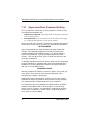
2&
:
#''
&
+1
BB /+(+9+
C76BC (" B A.$A<C76B
''#2,B32B'
%
Ethernet
(A
SBC8360 Socket370 All-in-One Petit Board Series User’s Manual
9*
SBC8360 Socket370 All-in-One Petit Board Series User’s Manual
'!$
3&%
0#
&'''""A(<
&'''"(/%#
%
%
C#77
/'#
;'(/*
3&)
+#
!"PCI parallel bus interface, version 2.1
!"Full native DOS games compatibility, via three
technologies:
#"
TDMA
#"
DDMA
#"
PC/PCI
!"Dynamic range (SNR) over 80dB
!"Integrated 3-D audio effects processor
!"High-Quality music synthesizer
3&
:
#''
2'9
6
B9* A. A<
A<'&
Audio Device
9"
SBC8360 Socket370 All-in-One Petit Board Series User’s Manual
9/
SBC8360 Socket370 All-in-One Petit Board Series User’s Manual
(
' )*#
6
2';2C'
;6C:#C2';6C=
'
&%
-
#'
'K
2B
NO
NO
$N#ON6O
N&O
%2':%2'=
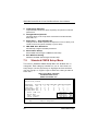
TO ENTER SETUP PRESS DEL KEY
'
2@@2B
G;&'&G
N#ON6O
NO
PRESS <F1> TO CONTINUE, <CTRL-ALT-ESC> OR <DEL> TO ENTER
SETUP
Award BIOS Utility
9(
SBC8360 Socket370 All-in-One Petit Board Series User’s Manual
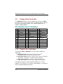
&)
6*
Up arrow
Down arrow
Left arrow
Right arrow
Esc key
PgUp/“+” key
PgDn/“−“ key
F1 key
(Shift) F2 key
F3 key
F4 key
F5 key
F6 key
F7 key
F8 key
F9 key
F10 key
&
Moves cursor to the previous item
Moves cursor to the next item
Moves cursor to the item on the left hand
Move to the item in the right hand
Main Menu -- Quits and deletes changes into CMOS
Status Page Setup Menu and Option Page Setup Menu -Exits current page and returns to Main Menu
Increases the numeric value or makes changes
Decreases the numeric value or makes changes
General help, only for Status Page Setup Menu and Option
Page Setup Menu
Change color from total 16 colors. F2 to select color
forward, (Shift) F2 to select color backward
Reserved
Reserved
Restores the previous CMOS value from CMOS, only for
Option Page Setup Menu
Loads the default CMOS value from BIOS default table,
only for Option Page Setup Menu
Loads the Setup default , only for Option Page Setup Menu
Reserved
Reserved
Saves all the CMOS changes, only for Main Menu
;-
.'
#" Main Menu
#" Status Page Setup Menu/Option Page Setup Menu
!
"
99
Award BIOS Utility
SBC8360 Socket370 All-in-One Petit Board Series User’s Manual
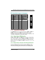
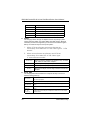
&1
"
"#
26
2'#C2'',C
CCC
+,
N&O
↑↓→← ! "
#$%& ' (
)*+,-*%./ 0!01
" 2%
%1345( 666
#" Standard CMOS Setup
#$%&
#" BIOS Features Setup
'
#" Chipset Features Setup
#" Power Management Setup
()(
#" PnP/PCI Configuration
$*+
(,'
#" Load BIOS Defaults
#$%&
)
Award BIOS Utility
9.
SBC8360 Socket370 All-in-One Petit Board Series User’s Manual
#" Load Setup Defaults
-
).
#" Integrated Peripherals
$/%$("0
&-&$0(-0
#" Supervisor / User Passwords
-0
&)1$
&02&
#" IDE HDD Auto Detection
'
#" Save & Exit Setup
&)-,%&)-,%&
#" Exit Without Saving
'
-,%&)
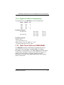
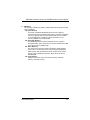
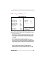
&2
"
#'
"#
'
#C2''C
"*
&
,
N%,ON%O
% )""3355,127!#8#99:
" )**"",$$$$$$
;<=<
1"%15% 10$$$$$$>>>>>>
1"%15!%& 0$$$$$$>>>>>>
0.3%15% 10$$$$$$>>>>>>
0.3%15!%& 0$$$$$$>>>>>>
1& #6??2@6A.% "015B?$;
1& 0. ' .3 3 "015#?@@B;
3 0
* 1 "015@8?;
%!
.!!11010%! "015#A@B$;
↑↓→← ! "C>03+5
# !()*+,-*%./ 0!01
9?
Award BIOS Utility
SBC8360 Socket370 All-in-One Petit Board Series User’s Manual
#" Date
0
3
day
date
month
year
The day of week, from Sun to Sat, determined by the BIOS,
is read only
The date, from 1 to 31 (or the maximum allowed in the
month), can key in the numerical / function key
The month, Jan through Dec.
The year, depends on the year of BIOS
#" Time
45
03677677
#" Primary Master/Primary Slave/Secondary
Master/Secondary Slave
)
58
4
"
$("#$%&58
1
1/9(/−
":
)
)
$
)
01
)
$10
"
"
)
)
$ (("&($0&'
$ ((&-&$0&:'
$ ((-(*%,0&:'
CYLS.
number of cylinders
LANDZONE
landing zone
HEADS
number of heads
SECTORS
number of sectors
write precom
MODE
HDD access mode
PRECOMP
$
)
0:%:"
"
#" Drive A type/Drive B type
)'
)#
Award BIOS Utility
9)
SBC8360 Socket370 All-in-One Petit Board Series User’s Manual
None
No floppy drive installed
360K, 5.25 in
5.25 inch PC-type standard drive; 360Kb capacity
1.2M, 5.25 in
5.25 inch AT-type high-density drive; 1.2MB capacity
720K, 3.5 in
3.5 inch double-sided drive; 720Kb capacity
1.44M, 3.5 in
3.5 inch double-sided drive; 1.44MB capacity
2.88M, 3.5 in
3.5 inch double-sided drive; 2.88MB capacity
#" Video
)
'
0
)
&;)6
1.
When VGA as primary and monochrome as
secondary, the selection for the video type is “VGA
Mode”.
2.
When monochrome as primary and VGA as
secondary, the selection of the video type
is ”Monochrome Mode”.
EGA/VGA
CGA 40
CGA 80
MONO
Enhanced Graphics Adapter/Video Graphics Array. For EGA,
VGA, SEGA, or PGA monitor adapters.
Color Graphics Adapter, power up in 40 column mode
Color Graphics Adapter, power up in 80 column mode
Monochrome adapter, includes high resolution monochrome
adapters
#" Error halt
9<
No errors
Whenever the BIOS detects a non-fatal error, the system will halt and
you will be prompted.
All errors
The system boot will not stop for any error detected.
All, But
Keyboard
System boot will not stop for a keyboard error; it will stop for all other
errors.
All, But
Diskette
System boot will not stop for a disk error; it will stop for all other
errors.
All, But
Disk/Key
System boot will not stop for a keyboard or disk error; it will stop for
all other errors.
Award BIOS Utility
SBC8360 Socket370 All-in-One Petit Board Series User’s Manual
#" Memory
%&<%&
=#$%&
!"Base Memory
%&#$%&
<
)=
)
84>84>
0?57>?57>
!"Extended Memory
#$%&
%&
),#
-1@
!"Other Memory
?57>745>
(%&
)
)
,
&
*',
!"Total Memory
&0
0
Award BIOS Utility
9A
SBC8360 Socket370 All-in-One Petit Board Series User’s Manual
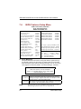
&3
0
+#
#'
"#
1 %1../
. 1.%!%* ' 1.%!%* -%* * 4./
10 01"E 1 %1 40D 1
. !+ 00 F . D%(!0((51& 00(!0((5 4
00("04%
% -$
(0.
5( "%% ./
5( "%% )*%1 ,
5( "% !%5) ,
15
(0.
%! .00(
/.+01
! +01GB?
(010+01 .9A
%E! 3
.%E! 3
.%E! 3
.%E! 3
.%E! 3
.%E! 3
22
%E! 3
%E! 3
.
%
%E! 3
B
-A$
(
%E! 3
.%E! 3
0.>
-
< 3 0
*%30D
.%E! 3
8$$$>*%30D
%E! 3
$$$>*%30D
%E! 3
$$$$>@*%30D
%E! 3
?$$$>:*%30D
%E! 3
8$$$>*%30D
%E! 3
$$$>*%30D
.%E! 3
5( )5( B,B?$'?8$-?
'(%.0.)!!1 .,%E! (!%55( 1./
.!5
(!%55( + 1
.!5
↑↓→← ! "
# !(C>03+5
A
!3%! )*+,-0!01
B0%3
+%!
:0%3 ( +%!
#" Virus Warning
(
0
);
)
Disabled
Disk boot sector is to be modified
Type "Y" to accept write or "N" to abort write
Award Software, Inc.
Enabled
Disabled
NOTE:
.*
Activates automatically when the system boots up causing a
warning message to appear when there is an attempt to access
the boot sector or hard disk partition table.
No warning message will appear when attempts to access the
boot sector or hard disk partition table are made.
This function is only available with DOS and other
operating systems that do not trap INT13.
Award BIOS Utility
SBC8360 Socket370 All-in-One Petit Board Series User’s Manual
#" CPU Internal Cache/External Cache
)0
-1/
Enabled-1
)
&-1$-'
Enabled
Disabled
Enable cache
Disable cache
#" CPU L2 Cache ECC Checking
!
0"---1(A4#
0
Enabled
#" Quick Power On Self Test
%&<%&=
$"
0#$%&
%&
Enabled
Enabled
Disabled
Enable Quick POST
Normal POST
#" Boot Sequence
$#,-
(%&
)'<
=0$#,-
)'0
)-<
=
)0#$%&
.
)$
)'
-0
$("
)(0"0
B&-&$
)
-(*%,
)
)
<0(%&=()A,C,SCSI
A,C,SCSI
System searches for the operating system from the floppy disk drive. If it
fails, it will search from the hard disk drive. If operating system is still not
found, it’ll seek from the SCSI device.
C,A,SCSI
System searches for the operating system from the hard disk drive first. If
it fails, it will search from the floppy disk drive. If operating system is still
not found, it’ll seek from the SCSI device.
C,CDROM,A
System searches for the operating system from the hard disk drive first. If
it fails, it will search from the IDE CDROM drive. If operating system is still
not found, it’ll seek from the floppy disk drive.
CDROM,C,A
System searches for the operating system from the IDE CDROM drive
first. If it fails, it will search from the hard disk drive. If operating system is
still not found, it’ll seek from the floppy disk drive.
D,A,SCSI
System searches for the operating system from the second IDE HDD first.
If it fails, it will search from the floppy disk drive. If operating system is
still not found, it’ll seek from the SCSI device.
Award BIOS Utility
."
SBC8360 Socket370 All-in-One Petit Board Series User’s Manual
E,A,SCSI
System searches for the operating system from the third IDE HDD first. If
it fails, it will search from the floppy disk drive. If operating system is still
not found, it’ll seek from the SCSI device.
F,A,SCSI
System searches for the operating system from the fourth IDE HDD first. If
it fails, it will search from the floppy disk drive. If operating system is still
not found, it’ll seek from the SCSI device.
SCSI,A,C
System searches for the operating system from the SCSI device first. If it
fails, it will search from the floppy disk drive. If operating system is still
not found, it’ll seek from the first IDE HDD.
SCSI,C,A
System searches for the operating system from the SCSI device first. If it
fails, it will search from the first IDE HDD. If operating system is still not
found, it’ll seek from the floppy disk drive.
C only
System only searches for the operating system from the first IDE HDD.
LS/ZIP,C
System searches for the operating system from the 120MB LS floppy or
the 100MB ZIP drive first. If it fails, it’ll search from the first IDE HDD.
#" Swap Floppy Drive
&()
!
0#$%&
)()'
()#0
()#()'#
0
Disabled.
#" Boot Up Floppy Seek
(%&0#$%&
)057C7
0
3?7>57D47>0
4,#
55,#C7
)Enabled
Enabled
BIOS searches for floppy disk drive to determine if it is 40 or 80
tracks. Note that BIOS can not tell from 720K, 1.2M or 1.44M drive
types as they are all 80 tracks.
Disabled
BIOS will not search for the type of floppy disk drive by track
number. There will be no warning message displayed if the drive
installed is 360K.
#" Boot Up NumLock Status
)On
On
Off
./
Keypad functions confine with numbers
Keypad functions convert to special functions (i.e., left/right
arrow keys)
Award BIOS Utility
SBC8360 Socket370 All-in-One Petit Board Series User’s Manual
#" Gate A20 Option
)Fast
Normal
Fast
The A20 signal is controlled by keyboard controller or chipset
hardware.
Default: Fast. The A20 signal is controlled by Port 92 or chipset
specific method.
#" Typematic Rate Setting
)
Disabled
Enabled
Enable typematic rate and typematic delay programming
Disabled
Disable typematic rate and typematic delay programming. The
system BIOS will use default value of these 2 items and the
default is controlled by keyboard.
#" Typematic Rate (Chars/Sec)
)6
6
8
10
12
15
20
24
30
6 characters per second
8 characters per second
10 characters per second
12 characters per second
15 characters per second
20 characters per second
24 characters per second
30 characters per second
#" Typematic Delay (Msec)
)
)250
250
250 msec
500
500 msec
750
750 msec
1000
1000 msec
#" Security Option
&02
&
)Setup
Award BIOS Utility
.(
SBC8360 Socket370 All-in-One Petit Board Series User’s Manual
System
Setup
NOTE:
The system will not boot and access to Setup will be denied if the
incorrect password is entered at the prompt.
The system will boot, but access to Setup will be denied if the
correct password is not entered at the prompt.
To disable security, select PASSWORD SETTING
at Main Menu and then you will be asked to
enter password. Do not type anything, just
press <Enter> and it will disable security. Once
the security is disabled, the system will boot
and you can enter Setup freely.
#" PCI/VGA Palette Snoop
&
EF'
,"F$&'/E"&'EF'-
-$/EF'!
0-$/EF',"F
$&'/E"&'EF'
!
0-$/EF'
,"F$&'/E"&'-
#" Assign IRQ for VGA
"
EF'($*+)
Enabled
Disabled
#" OS Select for DRAM >64
%&/4(*',
?5,#$%&/4
(*',
?5,#0)&%&4'0<
%&4=0
:%:%&4
)Non-OS2
#" Report No FDD For Win 95
!
G8$*+?<
)=
)
No
#" Video BIOS Shadow
E
)
)
#$%&
*', )0
)Enabled
Enabled
Disabled
Video BIOS shadowing is enabled
Video BIOS shadowing is disabled
#" C8000 - CBFFF Shadow/DC000 - DFFFF Shadow
*%,
*',
?>34>/
)Disabled
Enabled
Disabled
.9
Optional shadow is enabled
Optional shadow is disabled
Award BIOS Utility
SBC8360 Socket370 All-in-One Petit Board Series User’s Manual
NOTE:
1. For C8000-DFFFF option-ROM on PCI BIOS – BIOS
automatically enables the shadow RAM. User
does not have to select the item.
2. IDE second channel control:
Enable: enables secondary IDE port and BIOS
will assign IRQ15 for this port.
Disable: disables secondary IDE port and IRQ15
is available for other device(s). The item is
optional only for PCI BIOS.
3. Some sound cards have an onboard CD-ROM
controller that uses IDE Secondary Port. To
avoid PCI IDE conflict, disable the IDE
secondary channel control so that the CD-ROM
may work.
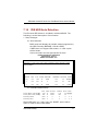
3& 8)#,;4(
4562'
456
#" LCD Type
'
EF'
A-(0#$%&
&
8A-()6
!"Type 1/13
1024 x 768
DSTN
!"Type 2
1280 x 1024
TFT
!"Type 3
640 x 480
DSTN
!"Type 4
800 x 600
DSTN
!"Type 5
640 x 480 (16bit)
TFT
!"Type 6
640 x 480 (24bit)
TFT
!"Type 7
1024 x 768
TFT
!"Type 8/9/10 800 x 600
TFT
!"Type 11/12
800 x 600
DSTN
!"Type 14
1280 x 1024
DSTN
!"Type 15
1024 x 600
DSTN
#" VGA Expansion (Full Screen)
))0
)
)"
(
Award BIOS Utility
..
SBC8360 Socket370 All-in-One Petit Board Series User’s Manual
#" Display Type During/After POST
)%&.!
incorrect display settingBoth0%&
.)
$Default0
EF'#$%&)-*%0
A-(%0#0
(
&
'
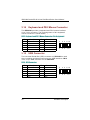
+#
#'
"#
'
#%,
-
SDRAM RAS-to-CAS Delay
SDRAM RAS Precharge Time
SDRAM CAS latency Time
SDRAM Precharge Control
DRAM Data Intgrity Mode
System BIOS Cacheable
Video BIOS Cacheable
Video RAM Cacheable
8 Bit I/O Recovery Time
16 Bit I/O Recovery Time
Memory Hole at 15M-16M
Passive Release
Delayed Transaction
AGP Aperture Size (MB)
:
:
:
:
:
:
:
:
:
:
:
:
:
:
3
3
Auto
Disabled
Non-ECC
Disabled
Disabled
Disabled
1
1
Disabled
Enabled
Disabled
64
CPU Warning Temperature
Current System1 Temp.
Current System2 Temp.
Current CPU Temperature
Current FAN1 Speed
Current FAN2 Speed
Current FAN3 Speed
Vcore :
VTTP :
Vcc3 :
+5V :
+ 12 V :
ESC
F1
F5
F6
F7
:
:
:
:
:
↑↓→←
Quit
Help
PU/PD/+/Old Values
(Shift)
Load BIOS Defaults
Load Setup Defaults
: Disabled
:
:
:
:
:
: Select Item
: Modify
F2 : Color
#" SDRAM RAS-to-CAS Delay
;*'&-'&
-A>43
)
0
(*',
(
)
(*',
-1
.?
Award BIOS Utility
SBC8360 Socket370 All-in-One Petit Board Series User’s Manual
#" SDRAM RAS Precharge Time
!(*',
0*'&
(*',(
)
)
2
3
#" SDRAM CAS latency Time
;-'& -A>4030'
)
0
(*',
()
(*',
-1
#" DRAM Data Integrity Mode
(*',
Non-ECC
#" System BIOS Cacheable
&"
#$%&*%,7777
0 )0
0
)
Disabled
#" Video BIOS Cacheable
E
#$%&*%,*',
E
&
)
#" Video RAM Cacheable
&"
)
#$%&*%,-7777
-D0)
)0
0
)
Disabled
#" 8/16 Bit I/O Recovery Time
$/%)
-$
$/%$&'
-$$&'
)<=?/C
$/%
)1C#$/%*)
1
?#$/%*)
#" Memory Hole at 15M-16M
;)$&'
*%,!
)
0
.
)Disabled
Award BIOS Utility
.)
SBC8360 Socket370 All-in-One Petit Board Series User’s Manual
#" Passive Release
!
0-1-$
)
%0-$
(*',
#" Delayed Transaction
34
&Enabled-$
)4)Enabled
Disabled
#" AGP Aperture Size (MB)
H
-$
'F
)5,0C,0?,034,0?5,0
4C,
48?,
#" Power Supply Type
)&AT
#" CPU Warning Temperature
-1
-1
)Disabled
#" Current System1/System 2/CPU Temperature
#" Current FAN1/FAN2/FAN3 Speed
*,
<)=-1
$-
#" Vcore/VTTP/VCC3/+5V/+12V
)
)
$-
.<
Award BIOS Utility
SBC8360 Socket370 All-in-One Petit Board Series User’s Manual
&4
"-$
#'
%C'
+.0.
%E! 3
0D 1%.%/ " .
0.10!E5
1 +. < I@>:29>#AJ2
1"%15$
HH !0%3!0E%!" 1& .HH
%E! 3
%E! 3
3 0
++ *03
<C!%.4
1"%15#
%E! 3
3 0
+++ 1
03 " 0K 03 %.3E503 ( .303 0D 10D.
*10! 55! >0.01
0+>
++E5 >
%4 (0.
%.3E5
@
%E! 3
%E! 3
%E! 3
%E! 3
B-6AL
%E! 3
.%.>
++
.%E! 3
0.3%15$
0.3%15#
!0((54
1%!01
%1%!! !01
%E!
%E!
%E!
.%E!
%E!
81 %4( .3
%E! 3
↑↓→← ! "
# !(C>03+5
A
!3%! )*+,-0!01
B0%3
+%!
:0%3 ( +%!
3
3
3
3
3
#" ACPI function
/
'
)
-
,<'-$=)"
0(
<
=
#" Power Management
<
=)
(H0&
0
&
6
Max Saving
User Define
Min Saving
Disabled
Award BIOS Utility
Maximum power savings. Only Available for SL CPUs.
Inactivity period is 1 minute in each mode.
Sets each mode individually. Select time-out periods in the
PM Timers section, following.
Minimum power savings. Inactivity period is 1 hour in each
mode (except the hard drive).
Default value
.A
SBC8360 Socket370 All-in-One Petit Board Series User’s Manual
#" PM Control by APM
$'
)
,<',=
0
;))
)Yes
No
Yes
System BIOS will ignore APM when power managing the system
System BIOS will wait for APM’s prompt before it enters any PM
mode (i.e., DOZE, STANDBY or SUSPEND).
Note: If APM is installed or if there is a task running, even when
the timer has timed out, the APM will not prompt the BIOS
to put the system into any power saving mode!
NOTE:
If APM is not installed, this option has no effect.
#" Video Off Method
(
Turns OFF vertical and horizontal synchronization
ports and writes blanks to the video buffer
Select this option if your monitor supports the Display
Power Management Signaling (DPMS) standard of the
Video Electronics Standards Association (VESA). Use
the software supplied for your video subsystem to
select video power management values.
System only writes blanks to the video buffer.
V/H SYNC+Blank
DPMS
Blank Screen
#" Video Off After
'))
0
)
Standby
NA
Suspend
Standby
Doze
NOTE:
System BIOS will never turn off the screen
Screen off when system is in SUSPEND mode
Screen off when system is in STANDBY mode
Screen off when system is in DOZE mode
Green monitors detect the V/H SYNC signals to turn off its
electron gun
#" Modem Use IRQ
3, 4, 5, 7, 9,
10, 11, NA
For external modem, 3 or 4 will be used for card type
modem. It is up to card definition. Default is 3.
#" Doze Mode
'
)<=0-1
)
?*
Award BIOS Utility
SBC8360 Socket370 All-in-One Petit Board Series User’s Manual
)Disabled
Disabled
1/2/4/6/8/10/20/30/40
Min/1 Hr
System will never enter doze mode
Defines the continuous idle time before the
system entering DOZE mode.
#" Standby Mode
'
)<=0
)
)
)
)Disabled
Disabled
1/2/4/6/8/10/20/30/40
Min/1 Hr
System will never enter STANDBY mode
Defines the continuous idle time before
the system entering STANDBY mode.
If any item defined in (J) is enabled &
active, STANDBY timer will be reloaded
#" Suspend Mode
'
)<=0
)-1
)Disabled
Disabled
1/2/4/6/8/10/20/30/40
Min/1 Hr
System will never enter SUSPEND mode
Defines the continuous idle time before the
system entering SUSPEND mode.
If any item defined in (J) is enabled &
active, SUSPEND timer will be reloaded
#" HDD Power Down
'
))<8=0
)
))
)
Disabled
Disabled
1/2/3/4/5/6/7/8/9/10/
11/12/13/14/15 Min
HDD’s motor will not power OFF.
Defines the continuous HDD idle time before
the HDD enters power saving mode (motor
OFF)
#" Throttle Duty Cycle
!(H
0-1
;
)62.5%
#" PCI/VGA Act-Monitor
!"
0)
)&
)Disabled
Award BIOS Utility
?"
SBC8360 Socket370 All-in-One Petit Board Series User’s Manual
#" Soft-Off by PWR-BTTN
'I$
%.
Instant-Off
(default)
This option follows the conventional manner systems perform
when power is turned OFF. Instant-Off is a soft power OFF
sequence requiring only the switching of the power supply button
to OFF.
Delay 4 Sec.
Upon turning OFF system from the power switch, this option will
delay the complete system power OFF sequence by
approximately 4 seconds. Within this delay period, system will
temporarily enter into Suspend Mode enabling you to restart the
system at once.
#" Wake Up on LAN
'
#" IRQ 8 Break Suspend
;$*+C<*-=
&
)
Disabled
#" Reload Global Timer Events
!Enabled0)
)
&
#" IRQ3 -7, 9-15, NMI
Primary IDE 0
Primary IDE 1
Secondary IDE 0
Secondary IDE 1
Floppy Disk
Serial Port
Parallel Port
?/
The
The
The
The
The
The
The
The
default
default
default
default
default
default
default
default
value
value
value
value
value
value
value
value
is
is
is
is
is
is
is
is
“Disabled”.
“Disabled”.
“Disabled”.
“Disabled”.
“Disabled”.
“Disabled”.
“Enabled”.
“Disabled”.
Award BIOS Utility
SBC8360 Socket370 All-in-One Petit Board Series User’s Manual
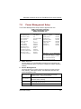
&5
0
(-#
#'
%#%#
%#$2
#%,
+
.%!! 3
0
01 0.10!! 35
%.%!
0.+/1%0.%%
%E! 3
>@
%/. 30 /%5
>?
%/. 30 /%5
>A
%/. 30.
>:
%/. 30 /%5
>9
%/. 30.
>#$
%/. 30 /%5
>##
%/. 30 /%5
>#-
%/. 30.
>#?
%/. 30.
>#A
%/. 30.
>$
%/. 30.
3E% %331
/.01
.E0%13* 1. 0010"
>#
>@
>A
>B
>:
↑↓→← ! "
# !(C>03+5
A
!3%! )*+,-0!01
B0%3
+%!
:0%3 ( +%!
%/.
%/.
%/.
%/.
%/.
30.
30.
30.
30.
30.
.%E! 3
%E! 3
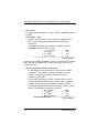
#" PNP OS Installed
&;)
<0!
G8=
)No
#" Resources Controlled By
'
#$%&
)$'0
.<$*+=0(,'0
1
(,'
0
#$%&
)Manual
Award BIOS Utility
?(
SBC8360 Socket370 All-in-One Petit Board Series User’s Manual
#" Reset Configuration Data
:0)
(
&"
"
&-(<"&-(=&)
)
Disabled
#" IRQ n Assigned to
!
0
0
)
6
Legacy ISA Devices compliant with the original PC
AT bus specification, requiring a specific interrupt
(such as IRQ4 for serial port 1).
2. PCI/ISA PnP Devices compliant with the Plug and
Play standard, whether designed for PCI or ISA bus
architecture.
1.
)$*+PCI/ISA PnP $*+8/G/4/5/8
Legacy ISA$*+3/5/D/7/
#" DMA n Assigned to
!
0(,'
0
)
6
Legacy ISA Devices compliant with the original PC
AT bus specification, requiring a specific DMA
channel.
2. PCI/ISA PnP Devices compliant with the Plug and
Play standard, whether designed for PCI or ISA bus
architecture.
1.
)(,'PCI/ISA PnP
#" Used MEM base addr
&
.
&N/A
#" Assign IRQ for USB
$*+1&#
)Enabled
#" OnBoard Ethernet BootROM
#$%&%&'!(
#*%,:)
?9
Award BIOS Utility
SBC8360 Socket370 All-in-One Petit Board Series User’s Manual
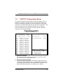
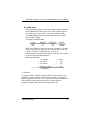
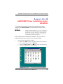
&%
0
(#
2';2C
STANDARD CMOS SETUP
INTEGRATED PERIPHERALS
BIOS FEATURES SETUP
SUPERVISOR PASSWORD
CHIPSET FEATURES SETUP
USER PASSWORD
POWER MANAGEMENT SETUP
IDE HDD AUTO DETECTION
PNP/PCI CONFIGURATION SAVE & EXIT SETUP
LOAD BIOS DEFAULTS
EXIT WITHOUT SAVING
LOAD SETUP DEFAULTS
ESC : Quit
$ % & ' : Select Item
F10 : Save & Exit Setup
(Shift)F2 : Change Color
Load BIOS Defaults except Standard CMOS Setup
2'
#C2'';6CK
B
Award BIOS Utility
?.
SBC8360 Socket370 All-in-One Petit Board Series User’s Manual
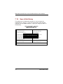
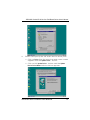
&%%
#'
(#
STANDARD CMOS SETUP
INTEGRATED PERIPHERALS
BIOS FEATURES SETUP
SUPERVISOR PASSWORD
CHIPSET FEATURES SETUP
USER PASSWORD
POWER MANAGEMENT SETUP
PNP/PCI CONFIGURATION
LOAD BIOS DEFAULTS
IDE HDD AUTO DETECTION
Load Setup Defaults (Y/N)? N
SAVE & EXIT SETUP
EXIT WITHOUT SAVING
LOAD SETUP DEFAULTS
ESC : Quit
$ % & ' : Select Item
F10 : Save & Exit Setup
(Shift)F2 : Change Color
Load BIOS Defaults except Standard CMOS Setup
'&,%
#C2'';6CK
B
??
Award BIOS Utility
SBC8360 Socket370 All-in-One Petit Board Series User’s Manual
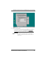
&%)
0-
'
IDE HDD Block Mode
: Enabled
Onboard Serial Port 2
: 2F8/IRQ3
IDE Primary Master PIO
: Auto
UART Mode Select
: Strandard
IDE Primary Slave PIO
: Auto
Onboard Parallel Port
: 378/IRQ7
IDE Secondary Master PIO
: Auto
Parallel Port Mode
: ECP+EPP
IDE Secondary Slave PIO
: Auto
ECP Mode Use DMA
:3
IDE Primary Master UDMA
IDE Primary Slave UDMA
IDE Secondary Master UDMA
IDE Secondary Slave UDMA
On-Chip Primary
PCI IDE
On-Chip Secondary PCI IDE
USB Keyboard Support
Init Display First
:
:
:
:
:
:
:
:
EPP Mode Select
Onboard Parallel Port 3
Onboard Parallel Port 4
: EPP1.7
: 3E8/IRQ10
: 2E8H/IRQ11
POWER ON Function
Onboard FDC Controller
Onboard Serial Port 1
: Button Only
: Enabled
: 3F8/IRQ4
Auto
Auto
Auto
Auto
Enabled
Enabled
Disabled
PCI/ISA
↑↓→←: Select Item
ESC: Quit
F1 : Help
PU / PD / + / - : Modify
F5 : Old Values
(Shift)F2 : Color
F6 : Load BIOS Defaults
F7 : Load Setup Defaults
: =6
+
#" IDE HDD Block Mode
#
0
0
/$$("
)
<
)
=0"
/
)
)
User Define
#" IDE Primary/Secondary Master/Slave PIO
$("$%<
$/%=
$%
<75=$("
)
$("
,
75)
)
$'
0
)
)Auto
#" IDE Primary/Secondary Master/Slave UDMA
1(,'/33$("
)
)
(,'
)
<!
G8%&*4
$("
)=$
)
1(,'/330'
#$%&
)Auto
Award BIOS Utility
?)
SBC8360 Socket370 All-in-One Petit Board Series User’s Manual
#" On-Chip Primary/Secondary PCI IDE
$("
$("&"
)
)Enabled
NOTE:
Choosing Disabled for these options will
automatically remove the IDE Primary Master/Slave
PIO and/or IDE Secondary Master/Slave PIO items
on the menu.
#" USB Keyboard Support
&"
1&#
)
1&#
)Disabled
#" Init Display First
)-$/$&'%
)PCI/ISA0
Onboard.
#" POWER ON Function
%:.
)Button-Only
BUTTONONLY
Follows the conventional way of turning OFF system power (via power
button).
Password
Upon selecting this option, the KB POWER ON Password line appears.
Press <Enter> and you’ll be prompted to enter and confirm a password of
your choice.
After setting the password, succeeding attempts to power ON the system
will result to null. For system to activate, user must input the password via
keyboard then press <Enter>.
Hot KEY
This option is very similar with that of Password. Hot-key combinations
range from Ctrl-F1 to Ctrl-F12. User may define this combination from the
Hot key Power ON option.
Mouse
Left
This allows system to POWER ON by clicking the left mouse button. To
enable, user must reboot and allow system to finish booting up otherwise
the setting will not take effect.
Mouse
Right
This allows system to POWER ON by clicking the right mouse button. To
enable this setting, user must reboot and allow system to finish the boot
up process otherwise the setting will not take effect.
#" Onboard FDC Controller
&"
<(-=
$
(-
)0(
)Enabled
?<
Award BIOS Utility
SBC8360 Socket370 All-in-One Petit Board Series User’s Manual
#" Onboard Serial Port 1/2/3/4
&
)3F8/IRQ4%
&0
2F8/IRQ3%
&403E8H/IRQ10%
&
30
2E8H/IRQ11%
&5
#" UART Mode Select
6
1.
2.
3.
IrDA
ASKIR IrDA-compliant serial infrared port
Standard (default value)
NOTE:
The UART Mode Select will not appear on the
menu once you disable the setting of Onboard
Serial Port 2.
,6;C
'6'D;6
;++6
;
#" Onboard Parallel Port
&A
<=
)378/IRQ7
NOTE:
Choosing Disabled for this option will remove the
Parallel Port Mode option on the menu.
#" Parallel Port Mode
&
<=&
:
.
)ECP+EPP
NOTE:
Selecting EPP on this option will allow selection
to the EPP Mode (EPP1.7, EPP1.9)
ECP mode selection will provide option for ECP
Mode Use DMA.
Choosing ECP+EPP modes will provide selections
for both EPP Mode Select and ECP Mode Use
DMA.
#" ECP Mode Use DMA
&(,'
#" EPP Mode Select
&"DG
Award BIOS Utility
?A
SBC8360 Socket370 All-in-One Petit Board Series User’s Manual
&%
#': -
K
1.
2.
supervisor password: can enter and change the options
of the setup menus.
user password: just can enter but do not have the right
to change the options of the setup menus.
ENTER PASSWORD:
N&O
#C2'K
N&OKN&O
1N&O
6
2
'
PASSWORD DISABLED.
'-
6
8
2'8
-
K
8
2'
@'C
''
'
8
''
'
)*
Award BIOS Utility
SBC8360 Socket370 All-in-One Petit Board Series User’s Manual
&%1
0
.
#
&&
6
2'
"'#
NO6
2'
0
B2;C6776F76;5&
0
76
76
,
=
< # )<,
A#B
##-$
#B
-
A#B
A-?
@
A#B
AB$
=
BAA@A
###9
A9
@-
$
###9
B@
@-
BAA@A
###9
A9
NO'
#C2''
< %3 1 0"(
%.3K0. 01 03 1"%15% 1 1)A#B,
##-$
#B
BAA@A
###9
A9 1"%15!%& 0. )-$@,
B8?
#B
BAA@A
B8A
@8 >>>>>>>>>>
0.3%15% 1
0. $
$
$
$
$ $
0.3%15!%& 0. $
$
$
$
$ $
0C2&
0
Award BIOS Utility
)"
SBC8360 Socket370 All-in-One Petit Board Series User’s Manual
/0C
6
2' ( 0 B2;C67 76 F
76;5&
!"B2;C67
5
2'
&
+
F
B2;C67
"*/9"?F?(
#
: "*/9=
+0
:
"?=
+'
:
?(=
+
: ."/=
./<C
0B2;C67
+
0-./<C-
P
!"LBA (Logical Block Addressing) mode
60
./<C
F
0
0&
F
0
)/
+0-
76
<95
#
: "*/9=
+0
: /..=
+'
:
?(=
+
: ."/=
<"95
Award BIOS Utility
SBC8360 Socket370 All-in-One Petit Board Series User’s Manual
!"4
71
&+
0
6
'
'&0"*/9
76:
76=
6
2'
0P
&+76;5&
#K7'
""/*
.?*
0&6'
"?
(/
'
.A
.A
C2&
B2;C67
76;5&
2'2':2'=
"*/9
/6
/6
B"(
0
P
C+0-
#
+ 0
+ '
+ : "*/9=
:
(/=
:
?(=
: ."/=
"5
(;
7676;5&
0
6
6
0';:B"(=0
76:76;5&=
2'B"(
Award BIOS Utility
)(
SBC8360 Socket370 All-in-One Petit Board Series User’s Manual
&%2
:
<
,
#'
K8
#C2'B
'
STANDARD CMOS SETUP
INTEGRATED PERIPHERALS
BIOS FEATURES SETUP
SUPERVISOR PASSWORD
CHIPSET FEATURES SETUP
USER PASSWORD
POWER MANAGEMENT SETUP
IDE HDD AUTO DETECTION
!"#$%
!&'()$*+
SAVE & EXIT SETUP
PNP/PCI CONFIGURATION
LOAD BIOS DEFAULTS
EXIT WITHOUT SAVING
LOAD SETUP DEFAULTS
ESC : Quit
F10 : Save & Exit Setup
$ % & ' : Select Item
(Shift) F2 : Change Color
Save Data to CMOS & Exit Setup
)9
Award BIOS Utility
SBC8360 Socket370 All-in-One Petit Board Series User’s Manual
&%3
,
8#
:-
'+'
K8
'
B
'
STANDARD CMOS SETUP
INTEGRATED PERIPHERALS
BIOS FEATURES SETUP
SUPERVISOR PASSWORD
CHIPSET FEATURES SETUP
USER PASSWORD
POWER MANAGEMENT SETUP
IDE HDD AUTO DETECTION
,-)$)$.%-$
!")&/+
PNP/PCI CONFIGURATION
SAVE & EXIT SETUP
LOAD BIOS DEFAULTS
EXIT WITHOUT SAVING
LOAD SETUP DEFAULTS
$ % & ' : Select Item
ESC : Quit
F10 : Save & Exit Setup
(Shift) F2 : Change Color
Abandon all Data & Exit Setup
&%
6
#C2'
#C2'
'
2@@2B
G;&'&GK
N#ON6O
NO
,
NO
2'
#C2'
Award BIOS Utility
).
SBC8360 Socket370 All-in-One Petit Board Series User’s Manual
)?
SBC8360 Socket370 All-in-One Petit Board Series User’s Manual
'+'
,
-
-
8-
+#
#%,
/*
:BC=
1@
Start
↓
Un-Lock WDT
:
OUT 120H 0AH ; enter WDT function
OUT 120H 0BH ; enable WDT function
↓
Set multiple (1~4)
:
OUT 120 0NH ; N=1,2,3 or 4
↓
Set base timer (0~F)
:
OUT 121 0MH ; M=0,1,2,…F
↓
re-set timer
:
OUT 121 0MH ; M=0,1,2,…F
↓
IF No re-set timer
:
WDT time-out, generate RESET or NMI
↓
IF to disable WDT
:
OUT 120 00H ; Can be disable at any time
↓
WDT counting
Watchdog Timer
))
SBC8360 Socket370 All-in-One Petit Board Series User’s Manual
M
0
1
2
3
4
5
6
7
8
9
A
B
C
D
E
F
)<
N
1
0.5 sec.
1 sec.
1.5 secs.
2 secs.
2.5 secs.
3 secs.
3.5 secs.
4 secs.
4.5 secs.
5 secs.
5.5 secs.
6 secs.
6.5 secs.
7 secs.
7.5 secs.
8 secs.
2
5
10
15
20
25
30
35
40
45
50
55
60
65
70
75
80
secs.
secs.
secs.
secs.
secs.
secs.
secs.
secs.
secs.
secs.
secs.
secs.
secs.
secs.
secs.
secs.
3
50
100
150
200
250
300
350
400
450
500
550
600
650
700
750
800
secs.
secs.
secs.
secs.
secs.
secs.
secs.
secs.
secs.
secs.
secs.
secs.
secs.
secs.
secs.
secs.
4
100
200
300
400
500
600
700
800
900
1000
1100
1200
1300
1400
1500
1600
secs.
secs.
secs.
secs.
secs.
secs.
secs.
secs.
secs.
secs.
secs.
secs.
secs.
secs.
secs.
secs.
Watchdog Timer
SBC8360 Socket370 All-in-One Petit Board Series User’s Manual
'+
'*!)./&!$
,0%.0
+
A<
IMPORTANT:
During Win95 installation, do not attempt to
install your Sound Card & Network Adapter
hardware outright; doing so will install the
older versions of the device drivers within
the Win95/98 setup program.
6 A.$A<
A.$A<
1.
Launch the Control Panel window
(" Select the Start button at the bottom left corner of
the screen then click on Settings.
(" Choose Control Panel from the list and the following
window appears on your display.
AUDIO/NET Driver Installation under Win95/98
)A
SBC8360 Socket370 All-in-One Petit Board Series User’s Manual
2.
Access the System Properties window
(" Double-click on the System icon and then choose
Device Manager from the menu.
(" A new window will pop-up with the Other Devices
represented by a “?” mark. Click this “?” mark and
2 devices marked with “?” appears on its subset
device list. One device specifies the PCI
Multimedia Audio; and another device specifies
the PCI Ethernet Controller. Refer to the following
illustration for a more accurate description.
3.
Enter the PCI Multimedia Audio Device Properties window
(" Insert the ESS1938S Driver for Win95/98 diskette into
your Drive A:.
(" Move the cursor to the PCI Multimedia Audio Device,
double-click your left mouse button and the PCI
Multimedia Audio Device Properties window pops up as
illustrated on the next page.
<*
AUDIO/NET Driver Installation under Win95/98
SBC8360 Socket370 All-in-One Petit Board Series User’s Manual
4.
Detect and specify the .INF audio device driver path
(" Click on Driver from the menu bar and a new screen
appears with the Update Driver... button.
(" Click on this Update Driver... button and the Update
Device Driver Wizard window below appears.
AUDIO/NET Driver Installation under Win95/98
<"
SBC8360 Socket370 All-in-One Petit Board Series User’s Manual
(" Choose Search for a better driver than the one your device
is using now then click on the Next> button to
proceed. The system then searches for the .INF
audio driver file starting from A: drive.
5.
Completing the installation
(" Once the driver file in Drive A: is detected, the
Update Device Driver Wizard window will list the
detected driver. Refer to the screen below.
(" Click on the Next button to complete the
installation of the ESS Solo-1 PCI AudioDrive.
6Finish ESS Solo-1 PCI AudioDrive Properties
#CloseSystem Properties
</
AUDIO/NET Driver Installation under Win95/98
SBC8360 Socket370 All-in-One Petit Board Series User’s Manual
6ESS Solo-1 PCI AudioDrive-8,2/
'
#
A.$A<
6.
Enter the PCI Ethernet Controller Properties window
(" Return back to the Device Manager window shown in
Step 2.
(" Insert the RTL8139 Net Device Driver for Win95/98 diskette
into Drive A:.
(" Move the cursor to the PCI Ethernet Controller
then double-click your left mouse button. The
screen then displays the PCI Ethernet Controller
Properties window.
AUDIO/NET Driver Installation under Win95/98
<(
SBC8360 Socket370 All-in-One Petit Board Series User’s Manual
7.
Detect and specify the .INF network device driver
path
(" Click on Driver from the menu bar and a new screen
appears with the Update Driver... button.
(" Click on this Update Driver... button and the Update
Device Driver Wizard window appears as shown on the
next page.
(" Choose Yes (Recommended) then click on the Next>
<9
AUDIO/NET Driver Installation under Win95/98
SBC8360 Socket370 All-in-One Petit Board Series User’s Manual
button to proceed. The system then searches for
the .INF network driver file starting from A: drive.
AUDIO/NET Driver Installation under Win95/98
<.
SBC8360 Socket370 All-in-One Petit Board Series User’s Manual
8.
Capping the installation
(" Once the network device driver in Drive A: is
detected, the Update Device Driver Wizard window will
list the detected driver.
(" Click on the Finish button to complete the
installation of the PCI Ethernet Controller.
9.
Provide Network Information
(" Right after completing the network adapter
installation, the system displays the Network window
requiring you to fill up your computer’s name, the
workgroup it will appear in, and a short description
of it. Refer to the following screen.
(" After filling up the items, press the Close button to
exit.
<?
AUDIO/NET Driver Installation under Win95/98
SBC8360 Socket370 All-in-One Petit Board Series User’s Manual
10.
Reboot the system
(" Your system will now ask you whether you’d like to
reset the computer. This signifies the successful
installation of your RTL8139 NET Device Driver into
Win95/98. Click on the Yes button.
NOTE:
We highly recommend that you reset the
system in order for the new network driver to
take effect.
AUDIO/NET Driver Installation under Win95/98
<)