1
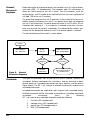
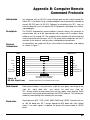
Appendix B: Computer Remote
Command Protocols
Introduction
Any computer with an RS-422 serial interface port can be used to control the
Rainin RP-1 Peristaltic Pump. Interface adapters are commercially available to
convert RS-232 ports to RS-422. Software for controlling the RP-1 from an
external computer must use specific RS-422 protocols, described in the following paragraphs.
Description
The RS-422 bidirectional communications channel allows the computer to
communicate with up to 64 slave devices with unique unit ID numbers, designated as units 0 through 63. The computer communicates with one pump at a
time by transmitting the pump’s unit ID. The pump which recognizes the unit ID
connects to the channel, and any other selected device disconnects.
Physical
Connections
All connections are made with 9-pin sub-miniature D-connectors and cabling
as shown in Figure 1.
PUMP
COMPUTER
1
1
RESERVED
1
1
6
6
RESERVED
6
6
OUT -
2
2
2
2
IN -
OUT +
7
7
7
7
IN +
IN -
3
3
3
3
OUT -
IN +
8
8
8
8
OUT +
CLOCK IN -
4
4
4
4
CLOCK OUT -
CLOCK IN +
9
9
9
9
CLOCK OUT +
5
5
RESERVED
5
5
M
F
9-CONDUCTOR FLAT CABLE
#28 AWG, 0.050 SPACING
M
F
Figure 10:
RS-422 SIgnal Lines
CONNECTORS ARE 9-PIN SUBMINIATURE D-TYPE
Data Format
Data communication is asynchronous, eight-bit, even parity, consisting of one
start bit, eight data bits, one parity bit and one stop bit.
RP-1 pumps check for even parity and use even parity when replying. Parity
error causes the pump to disconnect from the RS-422 channel. This can be corrected by reconnecting then restarting the message.
Baud rates
Baud rates are: 600, 1200, 2400, 4800, 9600 and 19200. The clock will run
at 16X the baud rate. RP-1 pumps operate at 600 baud with their internal
clocks. If no clock signal is supplied, the pump will communicate at 19200
baud.
21
Connect/
Disconnect
Sequence
Before connecting to a particular pump, the computer must first send a disconnect code (255 - FF hexadecimal). The computer waits 20 milliseconds to
allow any active device to turn off its driver. Then the computer sends the
desired pump’s unit ID number as an eight-bit byte with the most significant bit
set (add 128 to the unit ID number).
The pump that recognizes the unit ID connects its transmitter to the communications channel and echoes the unit ID. Any device which does not recognize
the unit ID will disconnect. The active pump will echo its unit ID within 20 milliseconds after receiving it — if no response is received in that time, the computer may assume the pump is unavailable. The selected pump remains connected until the disconnect code or the unit ID of another device is received.
The connect/disconnect flow chart is shown below.
START
DISCONNECT
ALL DEVICES
20 MS
DELAY
SEND SELECTED
UNIT ID NUMBER
N
20 MS
TIMEOUT
?
UNIT ID
ECHOED
?
N
Y
Figure 9: Connect/
Disconnect Sequence
Commands
ERROR
HANDLER
Y
SELECTED DEVICE
IS CONNECTED
Two types of commands can be sent via the RS-422 channel; buffered and
immediate. Buffered commands are instructions, and are executed as background processes. Immediate commands are status requests, and are given a
higher priority. The RP-1 will interrupt a buffered command to respond to an
immediate command.
Immediate commands are single-letter status requests with immediate priority.
Buffered commands will be interrupted to complete an immediate command.
Immediate
commands
(from
the
following
RP-1 set:) can be any valid data character except the following:
1
2
3
4
22
line-feed (0A hexadecimal)
carriage return (0D hexadecimal)
pound sign (23 hexadecimal) or
NAK (15 hexadecimal)
Immediate commands return messages of one or more characters. Each character must be sent within 20 milliseconds after the command character has
been transmitted. The first character is sent as a response to the command. The
computer gets additional characters in response by sending an ACK (6 hexadecimal). The last character of an immediate command has its most significant
bit set to 1. The host computer will not “ACK” it.
Buffered commands consist of an ASCII string of one or more characters preceded by a line feed <LF> (0A hexadecimal) and followed by a carriage return
<CR> (0D hexadecimal). The pump echoes with a line feed <LF> if ready for
a command and with a pound sign <#> (23 hexadecimal) if not ready. If not
ready, the computer retries sending the line feed until the pump echoes a line
feed.
Once the pump echoes the line feed, each subsequent character will be echoed
if there is no error. If there is an error, no echo will be made and the pump will
disconnect from the channel. If the computer is checking echoes and receives
one with an error, it can send a NAK (15 hexadecimal) and the pump will
retransmit the character.
The pump can be “locked” (put into “Remote” with the “L” buffered command.
When the pump is unlocked, it will ignore all buffered commands except the “L”
command.
A List of the RP-1 immediate and buffered commands follows:
Command
I
Command
List
Mode
I
Description
Request Contact Input Status
Return: “ab”
where “a” reflects pin 3 (START/STOP input) and “b” reflects pin 1
(CW/CCW input)
The allowable values are:
“1” for an inactive or high input (open)
“0” for an active or low input (closed)
Default response: “11”
Command
R
Mode
B
Description
Set a new speed
“Rn”
where “n” is a 1-4 digit integer interpreted as the value of the new speed
in hundredths of a revolution per minute. Example: “R1250” means
12.5 r.p.m. This command changes the speed of the pump if the mode
is in Remote control. If the speed given requires an increase in rotation
rate, a ramp is calculated and executed. If the new speed is less than
the present rotation rate, the effect is almost immediate.
23
Where direction (‘j’ command) and speed (‘R’ command) are to be
used, this ‘R’ command should precede the ‘j’.
See note at end of this document on how to set RPM given tubing type,
inside diameter, and desired flowrate.
Command
R
Mode
I
Description
Read Display
Return: “dXX.XXca”
Where “d” is the direction status
“ “ a space if stopped
“+” if CW
“-” if CCW
“XX.XX” is the speed status in rpm
“48.00” at full speed
“c” is the control status
“K” if started through the keypad
“R” if started through the contacts
or set to remote mode through GSIOC
“a” is the autostart condition
“*” if in autostart condition (display flashing)
“ “ a space if not in autostart
Default return: “ 12.50K “ when the pump is new.
S
B Set the mode
“SK” for Keypad control
“SR” for Remote control
Any other letter following the S is ignored. If the pump has been enabled
by the Run signal on its back panel, the pump will ignore this command
to change mode. The computer should check the results of this command by issuing the ‘?’ command.
Command
V
Mode
I
Description
Request Analog Input Status
Return: “vvv”
Where “vvv” is a 3 digit decimal number ranging from 000 to 255. A
response of 255 corresponds to 5V or open circuit.
The last character of the returned message has its high bit set.
Command
!
Mode
B
Description
Set Select Code
“!nn”
Where “nn” is the new select code for this instrument. The new code
can range from 00 through 63. This command instructs the instrument
to immediately change its select code because it will be selected through
this new code for all future commands. The pump must be locked for
this command to have any effect.
24
Command
%
Mode
I
Description
Module Identification
Return: “RP1V1.x”
Identifies the pump as a RP1 pump
(Note: Should be V1.9 or larger. If not, call
Technical Service, 800-543-4030 for newer chips.)
Command
j
Mode
B
Description
Set Direction
“jF” for forward (CW),
“jB” for Backwards (CCW)
Sets pump’s motor direction. Can be read in ‘d’ field of ? command. This
command has the “side effect” of starting the pump - just as the circular arrow keys do from the front panel. If the pump is stopped, this command will start it rotating at the currently defined rate. If the pump is
already rotating in the direction specified by this command, this command has no effect. If the pump is rotating, this command will reverse
the pump’s direction. The ‘R’ command, used to set the rotation rate,
should precede this command.
Command
L
Mode
B
Description
Lock. Enable Remote Control
Only the Stop key remains active. Pushing it once is enough to generate a “Panic Stop” condition.
Command
U
Mode
B
Description
Unlock. Exit Remote Control
Releases the pump from remote control, returning control to the keyboard.
Command
?
Mode
I
Description
Request Status
Return: “ceds”
where
“c” is control status: “K” is for keypad mode, “R” is for remote mode, “X”
is External Input Mode (from back panel).
“e” is for Error status. This is normally a blank. If the Stop key is hit, this
field becomes ‘S’. Once read by this command, it returns to being a
blank again.
“d” is direction of rotation: “F” for forward (CW when viewed from above)
and “B” for backwards (CCW)This definition does not require the pump
to be running.
“s” is “S” for stop (no motion), or “F” for flowing (rotating). This is independent of the panic stop error logic.
25
Because the command buffer is 40 characters long, a buffered command string
can be as long as 39 characters, the last character being the CR (carriage
return) ASCII code.
Note: Users want to set flowrates in mL/min while the pump must be controlled
in RPM. For the conversion, the computer will need to know the tubing material, inside diameter, and flowrate at some specified RPM. This information is
contained in the table below. Note that the conversion factor, RPM per unit
flowrate, can be obtained by dividing the MaxRPM (always 48 RPM for this
pump) by the “Max” flowrate value listed in the user manual column of that
name. For Polyvinyl Chloride (PVC) tubing of inside diameter 0.25 mm, the
Max flowrate listed is 0.33 mL/min (this value presumes 48 RPM). The computer will need to form a conversion factor of 48 / 0.33 or 144 (for this userspecified tubing). When the user’s method asks for a flowrate of 0.2 mL/min,
for example, the computer will have to calculate an RPM value of 0.2 x 144,
or 28.8 RPM. The corresponding ‘R’ command would then appear as ‘R2880’.
26