1
333 and 334 Pumps
User’s Guide
333 and 334 Pumps
User’s Guide
801422B/©2000 Gilson S. A. All rights reserved
February 2000
Table of Contents
Safety
Declaration of Conformity
1 Introduction
Notational Conventions and Units ............................................ 1-2
Software Related Conventions (331 Pump) ....................... 1-2
Units and Conversion Factors .............................................. 1-2
Overview ........................................................................................ 1-4
User’s Guide Description and Applicability ..................... 1-4
Hardware Description ............................................................ 1-5
331 Pump Software Description ........................................... 1-5
Operating Principle ................................................................ 1-6
Unpacking ...................................................................................... 1-7
Hardware .................................................................................. 1-7
Software .................................................................................... 1-7
Warranty ......................................................................................... 1-8
Customer Service .......................................................................... 1-9
2 Description
331 Pump’s Hydraulic Components ......................................... 2-3
332 Pump’s Hydraulic Components ..............................................
Pressure Module ...................................................................... 2-3
Outlet Filter .............................................................................. 2-3
Pump Heads .................................................................................. 2-4
Optional Components .................................................................. 2-5
Solvent Valve Block ................................................................ 2-5
Solvent Degasser ..................................................................... 2-5
333 Pump Control Components ................................................. 2-6
Control Panel ........................................................................... 2-6
Stand-by Panel ......................................................................... 2-7
Rear Panel - Electrical Connectors ............................................. 2-8
Power Connector ..................................................................... 2-9
Input/Output Signal Connectors (333 Pump) .................. 2-9
GSIOC Connectors .................................................................. 2-9
Accessories ................................................................................... 2-10
Table of Contents-1
3 Installation
Electrical Connections – Switching On ..................................... 3-2
Power Supply ........................................................................... 3-2
Fuse Installation and Voltage Selection .............................. 3-2
Switching-on ............................................................................ 3-2
Electrical Connections - Communications ............................... 3-3
Contact Connections ............................................................... 3-3
Powering an External Relay .................................................. 3-4
Output Signals ......................................................................... 3-4
Input Signals ............................................................................ 3-4
GSIOC Connections ................................................................ 3-6
GSIOC ID .................................................................................. 3-7
Bit Rate ...................................................................................... 3-7
Twin Pump Systems ............................................................... 3-8
Hydraulic Connections ................................................................ 3-9
Solvent Inlet Lines ................................................................... 3-9
Piston Rinsing Chamber ...................................................... 3-10
Injector Connection ............................................................... 3-10
Drip Tray ................................................................................. 3-11
Solvent Valve Block Installation ......................................... 3-11
Pump Head Installation ....................................................... 3-11
Accessories ................................................................................... 3-12
Degasser .................................................................................. 3-12
Column Holder ...................................................................... 3-12
Solvent-bottle Tray ................................................................ 3-14
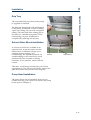
Positioning the Pumps ............................................................... 3-15
Horizontal Configuration .................................................... 3-15
Vertical Stacking .................................................................... 3-16
Setting-up ..................................................................................... 3-17
Basic Elements ....................................................................... 3-17
Config. Example 1: Binary Gradient or Isocratic ............ 3-19
Config. Example 2: Solvent Mixing and Injection .......... 3-22
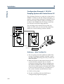
Config. Example 3:
333-334 Pumping System with Control from a PC ......... 3-24
4 Software
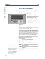
Using the Control Panel ............................................................... 4-2
Display Unit ............................................................................. 4-2
Keypad ...................................................................................... 4-2
Switching On the Pump ............................................................... 4-3
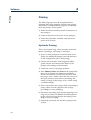
Priming ........................................................................................... 4-4
Hydraulic Priming .................................................................. 4-4
After Priming ........................................................................... 4-5
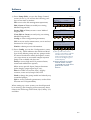
Configuring .................................................................................... 4-6
Introduction .............................................................................. 4-6
Procedure .................................................................................. 4-6
Table of Contents-2
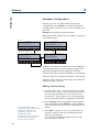
Hardware Configuration ....................................................... 4-8
Hydraulic Configuration ....................................................... 4-9
Safety Functions .................................................................... 4-13
Electrical Contacts ................................................................. 4-15
GSIOC ID and Miscellaneous ............................................. 4-16
Manual Operations ..................................................................... 4-18
Introduction ............................................................................ 4-18
Procedure ................................................................................ 4-18
Hydraulic Priming ................................................................ 4-18
Manual Flow Control ........................................................... 4-19
Output ..................................................................................... 4-20
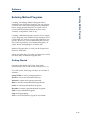
Entering Method Programs ....................................................... 4-21
Getting Started ....................................................................... 4-21
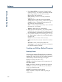
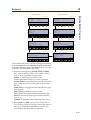
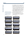
Creating and Editing Method Programs .......................... 4-22
Method Program Work Sheet ............................................. 4-29
File Management ......................................................................... 4-30
Procedure ................................................................................ 4-30
Good Laboratory Practice (GLP) Functions ........................... 4-33
Procedure ................................................................................ 4-33
Audit Trail .............................................................................. 4-34
Dismounting Pump Heads and
Accessing Maintenance Logs .............................................. 4-34
Seal Installation ..................................................................... 4-36
Leak Test ................................................................................. 4-38
Mixing Test ............................................................................. 4-38
Running a Method Program ..................................................... 4-39
Preparing for a Run .............................................................. 4-39
Starting and Stopping a Run ............................................... 4-39
Post Run Information ........................................................... 4-41
Information Transfer ............................................................. 4-42
Control of A Model 15X Detector ............................................ 4-44
Introduction ............................................................................ 4-44
Procedure ................................................................................ 4-44
Software Functions ............................................................... 4-45
PC Software for 333 and 334 Pump Control .......................... 4-46
5 Maintenance and Troubleshooting
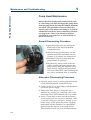
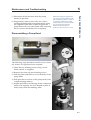
Pump Head Maintenance ............................................................ 5-2
Normal Dismounting Procedure .......................................... 5-2
Alternative Dismounting Procedure ................................... 5-2
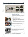
Disassembling a Pump Head ................................................ 5-3
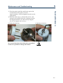
Replacing a Piston Seal .......................................................... 5-4
Piston Rinsing Chamber ........................................................ 5-4
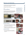
Piston and Bellows .................................................................. 5-5
Reassembling a Pump Head ................................................. 5-6
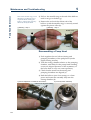
Check Valves .................................................................................. 5-8
Cleaning a Check Valve ......................................................... 5-8
Table of Contents-3
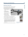
Replacing a Check Valve ........................................................ 5-9
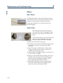
Filters ............................................................................................. 5-10
Inlet Filters .............................................................................. 5-10
Outlet Filter ............................................................................ 5-10
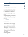
Troubleshooting ........................................................................... 5-11
Error LED (333 Pump) .......................................................... 5-11
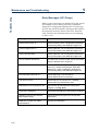
Error Messages (333 Pump) ................................................ 5-12
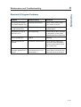
Electrical & Program Problems .......................................... 5-13
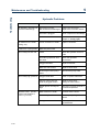
Hydraulic Problems .............................................................. 5-14
6 Reference Information
Technical Data ............................................................................... 6-2
Gilson 333 and 334 (33X) Pumps.......................................... 6-2
Working Range & Performance Data .................................. 6-3
Control Characteristics ........................................................... 6-6
Hydraulic Components .......................................................... 6-9
Quality References ................................................................ 6-11
Environmental Conditions .................................................. 6-12
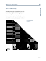
Solvent Miscibility ...................................................................... 6-13
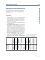
Flow Rate Accuracy .................................................................... 6-14
Principle .................................................................................. 6-14
Adjustments ........................................................................... 6-15
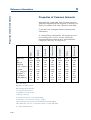
Properties of Common Solvents ............................................... 6-16
Safety Data for Flammable Solvents ....................................... 6-17
Definitions .............................................................................. 6-17
References ............................................................................... 6-18
Abbreviations for Thermoplastic Materials ........................... 6-19
Part Numbers ............................................................................... 6-20
Gilson 333 Pump ................................................................... 6-20
Gilson 334 Pump ................................................................... 6-22
Additional Accessories for 333 and 334 Pumps .............. 6-23
7 GSIOC
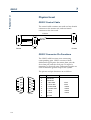
Physical Levell ............................................................................... 7-2
GSIOC Control Cable ............................................................. 7-2
GSIOC Connector Pin Functions .......................................... 7-2
Electrical Level .............................................................................. 7-3
Bit Rates .................................................................................... 7-3
GSIOC IDs ................................................................................ 7-4
Character Level & Format ........................................................... 7-5
Disconnect and Connect Sequences .......................................... 7-6
Immediate Command Protocol .................................................. 7-7
Introduction to GSIOC Commands ........................................... 7-8
Commands for 333 and 334 Pumps ........................................... 7-9
Operational Functions ............................................................ 7-9
Maintenance Functions ........................................................ 7-10
Description of Commands ................................................... 7-10
Table of Contents-4
Safety
Read this section carefully before installing and operating the pump.
For safe and correct use of the pump, it is essential that both operating and service
personnel follow generally accepted safety procedures as well as the safety instructions
given in this document, the 333 and 334 Pump User’s Guide.
The instruments described in this document are piston pumps, which should only be
used in an indoor environment for pumping purposes by qualified personnel. If a 333
Pump, or a 334 Pump, is used in a manner not specified by Gilson, the protection
provided by the pump may be impaired.
Voltages present inside the 333 and 334 Pumps are potentially dangerous. If there is a
problem with any pump, the power cable should be removed until qualified service
personnel have repaired it. This is to prevent anyone from inadvertently using the
pump, thus causing possible harm to themselves, or damage to the pump itself.
The leakage current of a 333 Pump, and of a 334 Pump, is within the limits allowed by
safety standards of laboratory equipment. An efficient ground connection is imperative
for the physical protection of the user.
Power supply cord reference 500005 is for use in France and Germany. Power supply
cord reference 500006 is for use in USA and Canada. For other countries contact your
local Gilson distributor.
The maximum voltage for any electrical device connected to each input or output
contact of a 333 Pump is 48 V.
However, adequate protection including clothing and ventilation must be provided if
dangerous liquids are used. In case of incidental spillage, carefully wipe with a dry cloth,
taking into account the nature of the spilled liquid and the necessary safety precautions.
Safety-1
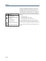
Safety
Symbol Explanation
~
Alternating current
PROTECTIVE CONDUCTOR
TERMINAL
I
On (Supply switch)
O
Off (Supply switch)
Caution, risk of electric shock
!
Safety-2
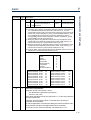
Caution (refer to User’s Guide)
Cleaning, dismantling, maintenance, adjustment
and repair should only be performed by personnel
trained in such work, and who are aware of the
possible dangers involved. Neither a 333 Pump, nor
a 334 Pump, nor the pump heads, may be sterilized,
using an autoclave, or any other device. When you
need to clean a pump, use one of the three following
methods:
1 - a clean dry cloth,
2 - a cloth dampened with water,
3 - a cloth dampened with soapy water.
If a cloth dampened with soapy water is used to
clean the pump, only domestic soap may be used.
No other form of detergent or chemical may be used.
These electronic and hazard symbols appear on the
pump:
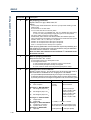
Declaration of Conformity
Application of Council Directives:
89/336/EEC and 73/23/EEC
Standards to which Conformity is Declared:
Electromagnetic Compatibility:
EN 50081-1 (1992) and EN 50081-2 (1992) for emission
EN 50082-1 (1998) and EN 50082-2 (1995) for immunity
Safety:
EN61010-1, (1993, including AMD A2: 1995),
UL 3101-1 (1993) and CAN/CSA 1010-1 (1992, including MOD2:
1997)
Manufacturer:
Gilson S.A.
72, rue Gambetta
BP45
95400 Villiers-le-Bel
France
Type of Equipment:
Laboratory Equipment
Product:
333 and 334 Pumps
Beginning with Serial Number:
196534 for 333 and 196540 for 334
I, the undersigned, hereby declare that the equipment specified above,
conforms to the above Directives and Standards.
Hervé Le Dorze
Quality Assurance Manager
Place: Sarcelles
Issue Date: 03/01/2000
The Gilson S.A. quality assurance system is registered as complying with ISO 9001
International Quality Standard, Registration Certificates No. 6621 and No. 18623 BVQI.
Declaration of Conformity-1
Introduction
1
Gilson 333 and 334 single-solvent pumps are for use in preparative chromatography
(20 to 100 mm bore columns). Described in this User’s Guide they are individually known
as 333 Pumps and 334 Pumps. Also described is Gilson 333-334, as a gradient system.
1-1
1
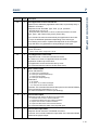
Notational Conventions and Units
Introduction
Notational Conventions and Units
Software Related Conventions (333 Pump)
The software displays messages and read only values
on the control panel’s screen as normal typeface
inside a frame. This convention is followed in this
User’s Guide.
For software options where a key must be pressed, the
related function is represented in bold (e.g. Edit, HELP).
When time is expressed in minutes it is to two
decimal places. For example, 7.75 min is actually 7
minutes and 45 seconds.
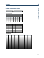
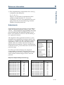
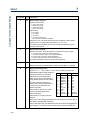
Units and Conversion Factors
Conversion Factors
To Convert
from:
atm
atm
bar
MPa
psi
1
0.987
9.87
0.068
International System of Units (SI)
Multiply by:
bar
MPa
1.013
1
10
0.069
0.101
0.1
1
0.0069
psi
14.7
14.5
145
1
1 atm = 760 mm Hg = 104 mm H2O
1 hPa = 1 mbar = 10 mm H2O
1 mm Hg = 1 Torr = 1.33 mbar = 133 Pa =
0.0193 psi
SI units are used in this document for specifications
and reference data, although “Units in Use with the
SI Unit” (e.g. bar and liter) are used in appropriate
contexts.
The following information comes from the Handbook
of Chemistry and Physics, 79th edition by D. R. Lide,
CRC Press, 1998-1999, Section 1.19-23.
Name, Symbol, and Conversion factors
Pressure (Derived Unit)
Name of the SI Unit: pascal (symbol: Pa)
Unit in Use with the SI Unit: bar (symbol: bar)
Thermodynamic Temperature (Base Unit)
Name of the SI Unit: kelvin (symbol: K)
T(K) = T (°C) + 273
T (°C) = [ T(°F) – 32] / 1.8
T (°F) = [1.8 x T(°C)] + 32
Length (Base Unit)
Name of the SI Unit: meter (symbol: m)
1 m = 3.28 feet = 39.4 inches
1 foot = 30.5 cm
1 inch = 25.4 mm
1-2
1
Introduction
Weight (Base Unit)
Name of the SI Unit: kilogram (symbol: kg)
1 kg = 2.20 pounds
1 pound = 0.454 kg
Prefixes
Multiples
Submultiples
Factor Prefix Symbol Factor Prefix Symbol
Prefix symbols should be printed in
roman type (upright) with no space
between the prefix and the unit
symbol (e.g. km for kilometer).
Prefixes are not to be used with
temperature units.
101
102
103
106
109
1012
1015
1018
1021
1024
deka
hecto
kilo
mega
giga
tera
peta
exa
zetta
yotta
da
h
k
M
G
T
P
E
Z
Y
10-1
10-2
10-3
10-6
10-9
10-12
10-15
10-18
10-21
10-24
deci
centi
milli
micro
nano
pico
femto
atto
zepto
yocto
Notational Conventions and Units
Volume (Derived Unit)
Name of the SI Unit: cubic meter (symbol: m3)
Unit in Use Together with the SI: liter (symbol: liter,
l or L).
1 liter = 1 dm3 = 1000 cm3
1 gallon (UK, liquid) = 4.55 liter
1 gallon (USA, liquid) = 3.79 liter
d
c
m
µ
n
p
f
a
z
y
1-3
1
Overview
Introduction
Overview
User’s Guide Description and Applicability
This user’s guide is both for 333 Pumps and for 334
Pumps. Information that applies uniquely to one or
other of these models is clearly identified at the
appropriate point. Except for the absence of two
components, no distinction is made at the hydraulic
level between the 334 (extra solvent remote-controlled
pump) and the 333 (primary solvent master-pump),
so much of this type of information (e.g. Chapters 2
and 5) relates to both 333 and 334 Pumps.
There are differences at the physical and electrical
level: 334 Pumps have no control panel or output
connector, so the information relating to the pump’s
software (e.g. Chapter 4) is only directly relevant to
a 333 Pump.
Chapter 1 contains brief descriptions of 333 and 334
Pumps, together with unpacking instructions, and
warranty details.
Chapter 2 contains descriptions of 333 and 334 Pump’s
major components.
Chapter 3 contains instructions for installing, and
setting-up 333 and 334 Pumps.
Chapter 4 contains details of the 333 Pump software
used for configuration and control. Directly, this
information only concerns 333 Pumps. However,
there are implications for any 334 Pumps controlled
from a 333 Pump.
If you use external software to control 33X Pumps
(up to three), you should refer to the manual for the
controlling software (e.g. UniPoint). Some
supplementary information has been included
relating to UniPoint and GLP functions.
Chapter 5 applies to 333 and 334 Pumps; it describes
preventive maintenance, troubleshooting, and
procedures for dismounting the heads.
1-4
Introduction
Overview
Chapter 6 contains reference information, relevant
to 333 and 334 Pumps: specifications, technical data,
hydraulic parameter information (solvent miscibility
and compressibility corrections), and separate parts
lists (items and references) for each pump model.
1
Chapter 7 contains information relating to GSIOC
control and a list of available commands.
Hardware Description
333 and 334 Pumps are reciprocating piston pumps
for preparative chromatography using from 20 mm
to 100 mm bore columns. Individually, they are for
single solvent delivery under high pressure. Each
33X Pump is equipped with two pump heads.
333 Pumps are master pumps designed to pump up
to three solvents (depending on the configuration).
They also have an integrated pressure, purge and
mixing module (PPMM), an outlet filter, and
optionally a solvent valve block.
333 Pumps have a control panel (integral keypad
and screen) for configuring, programming, and
coordinating with other equipment (pumps,
detectors, injectors, etc.).
334 Pumps are designed as slave pumps for delivery
of a second solvent (B) and (with two additional 334
Pumps) a third solvent (C), to be mixed with the
primary solvent (A) pumped by the 333.
334 Pumps have no PPMM, no outlet filter, and
because they have no control panel they are
physically shorter. They may be controlled by 333
Pump software using its control panel, or by PC based
software such as Gilson’s UniPoint and GSIOC
(Gilson Serial Input-Output Channel) commands.
333 Pump Software Description
Although the pre-installed software is designed to be
user-friendly, you are advised to read this guide carefully before using the pump. Programming consists
of entering configuration details for your pump, and
then a sequence of events (flow rate, composition,
electrical contacts, etc.) as a Method Program.
1-5
1
Overview
Introduction
By means of the pre-installed software (or PC based
software), a 333 Pump may be used to control a Gilson
detector and up to three other pumps, of the following
types: a 334 Pump, Gilson 30X Series Pumps (with any
head), or another 333 Pump. If solvent injection is
required, the injection pump must be of the 30X Series.
Alternatively, you may use Gilson UniPoint™ system
software to control 333 and 334 Pumps, and associated
Gilson equipment (via Gilson 506C interface and
GSIOC slave bus). Coordination with any other
instrument is carried out by electrical contacts.
One of the following Gilson detectors (UV-vis
absorbance detection) may also be controlled from a
333 Pump: single-wavelength Model 151 or 152,
dual-wavelength Model 155 or 156. You should refer
to the user’s guide of the relevant detector for full
information, including soft-key functions that are
accessible from the control panel of a 333 Pump.
Operating Principle
You have to go through three main steps before
running your 333 Pump based Method Program:
1) Define the system configuration (enter
descriptions of your pumping system’s hardware).
2) Select the type of events and key in the related
parameters (flow rate, composition, and
coordination). The Method Program (configuration,
list of events and associated parameters) is saved
automatically by the software.
3) Initialize the system by priming the solvent
channels; then run the Method Program.
1-6
Introduction
Hardware
Unpacking
Unpacking
1
You are advised to check your pump immediately,
even if it is not to be used until later. Upon receipt of
your instrument, unpack the unit carefully, inspect it
for possible damage, and check the contents of each
carton against the list of parts and accessories given
in the Chapter 6. Your supplier should be notified
immediately of any inconsistencies or any damage.
Your pump is delivered in a crate containing the
main module and accessories. The original packing
should be kept, especially for the period during
which the instrument is under warranty, in case the
equipment has to be returned to the factory.
Because of their weight (about 35 kg, 44 kg packed),
you should take special care when handling the
large cartons. Pump modules are heavy and should
be lifted from the carton with care, by two persons.
Instructions describing the unpacking procedures
are to be found on and in the carton.
Software
The software is pre-installed and is accessible, using
the control panel, immediately after switching on a
333 Pump.
1-7
1
Warranty
Introduction
1-8
Warranty
If the pump does not appear to function correctly,
first verify the electrical connections are correct and
that the instrument is switched on. Contact your
Gilson distributor for technical advice or possibly a
service visit. Any service required will be given
within the warranty conditions assured by your
Gilson distributor.
Introduction
Gilson and its worldwide network of authorized
distributors provide customers with four types of
assistance: sales, technical, applications and service.
Customer Service personnel are able to serve you
more efficiently if you provide the following
information.
Customer Service
Customer Service
1
1) The serial number and model number of the
equipment involved.
2) Type of computer (if used), available memory,
microprocessor and software version(s) in
operation.
3) The installation procedure you used.
4) A concise list of the symptoms.
5) A list of operating procedures and conditions you
were using when the problem arose.
6) A list of other devices connected to the system
and a system diagram showing the connections.
7) A list of other electrical connections in the room.
1-9
Introduction
1-10
1
Description
2
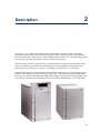
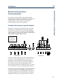
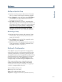
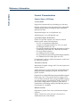
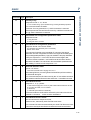
The front of a 333 Pump incorporates the control panel, and the pump’s principal
hydraulic components, which are pre-mounted. The hydraulics may be concealed by
the removable door. Also shown is the standby panel, which shows the operating status
of the pump, and may be used to switch on and off the pump.
The 334 Pump, which is shorter, has no control panel and operates in the slave mode.
There is a drip tray at the bottom of both pumps. Solvent bottles can be placed in a
removable tray at the top of a 333 or a 334 Pump, on the bench, or on the floor.
A single 333 Pump is for use in the isocratic mode. By adding one or two 334 Pumps two or
three solvents may be mixed. By adding a 30X pump, solvent injection may be performed.
However, in total no more than three additional pumps of any type may be controlled from
a 333 Pump, whether the controlled pumps be used for mobile phase, or for injection.
2-1
2
Description
Standby Panel
Control panel
Standby Panel
Solvent Tray
Inlet Tee
Outlet Tee
Pump Heads
Hydraulics
2-2
Drip Tray
Door
Drip Tray
Door
2
Description
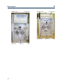
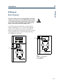
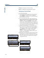
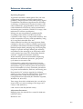
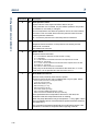
The principal hydraulic components of a
333 Pump are: pump heads, PPMM, and
the outlet filter. Construction characteristics
are given in Chapter 6.
For Pump 1 the filtered-solvent line
connects to the inlet-tee; outlets from the
tee connect to the pump heads (1L and 1R),
thus the motors pump the same solvent (A)
to the pressure module. For Pumps 2 and 3
the heads are respectively designated 2L
and 2R for solvent B, plus 3L and 3R for
solvent C.
Purge Valve (PV)
Outlet Filter (OF)
Two reciprocating pump motors are
contained within the body of the pump.
The tops of the pump motors protrude
through the front panel.
Pressure/Purge/Mixing Module
(PPMM)
Purge Line
333 Pump’s Hydraulic Components
333 Pump’s Hydraulic Components
Inlet Tee
Pump Head (L)
Pump Head (R)
Pressure, Purge and Mixing Module
(PPMM)
Three functions are combined in the PPMM:
- a pressure transducer (0-60 MPa),
- a static mixer to blend up to 3 solvents under high
pressure (2.85 ml chamber volume),
- a purge valve to manually switch the mobile phase
between outlet filter and drain.
To operate the purge valve, turn the black knob fully
clockwise to direct the flow to the outlet filter, fully
counterclockwise to direct the flow to the atmospheric
purge-outlet.
Outlet Filter
The outlet filter (Upchurch A332) characteristics are:
10 µm threshold, 1.6 mm thickness, 19 mm diameter,
and 160 µl total internal volume.
2-3
2
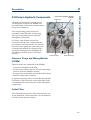
Pump Heads
Description
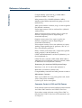
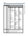
Pump Heads
Solvent Outlet Line
H3 pump heads for preparative use (flow rates
between 0.20 and 200 ml/minute, 21 MPa) are premounted directly onto the tops of the driving
mechanisms, which have the same axis as the piston
motors, so pump heads may be serviced with
relative ease. The pump heads must be dismounted
for routine servicing purposes (e.g. changing a
piston seal).
Each head has a solvent inlet port, a solvent outlet
port, an inlet port to the rinsing chamber, an outlet
port from the rinsing chamber, and a reciprocating
piston. Shown here are the external components, the
internal components are described in Chapter 5
(Maintenance).
Solvent Inlet (Check-Valve)
2-4
The piston seal and the bellows are inside the pump
head. The solvent inlet port and the solvent outlet
port are fitted with connectors containing the check
valves. All of these items can be serviced by the user.
Description
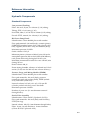
Solvent Valve Block
Up to four solvent lines may be connected to the
solvent block of each configured 333 or 334 Pump.
These solvents may be switched under software
control. Thus a two-solvent workstation, where each
pump is equipped in this way, permits selection of
solvents A1 to A4 from Pump A and B1 to B4 from
Pump B. Adding a third pump enables you to select
solvents C1 to C4.
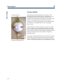
Optional Components
Optional Components
2
Solvent Degasser
The Gilson 864 Degasser is an on-line solvent degasser
with four channels, operating under a vacuum of
70 hPa. It maximizes the stability of the chromatographic results by removing dissolved gasses from
solvents, down to less than 0.4 ppm, for oxygen
dissolved in water, at a flow rate of 1 ml/minute. It is
compatible with 33X Pumps up to 10 ml/min (50 ml/
min with water) to maintain flow rate accuracy.
2-5
2
333 Pump Control Components
Description
333 Pump Control Components
The components for controlling from a 333 Pump are
at the front of the instrument. All electrical
connections are made at the rear.
Control Panel
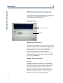
Display Unit (Screen)
Keypad
Display Unit and Screens
The 40-character, 8-line unit is used to display sets of
information: parameters, commands, messages (time
related events, flow rates, solvent composition, inrun information, etc.), and soft-key functions.
A ‘screen’ comprises of a set of information,
depending on the software and the choices that you
make. Each screen has a unique number, accessible
by pressing the HELP key.
Keypad and Function Keys
Soft-keys
The bottom line of the display unit is reserved for
labeling six variable-function soft-keys (identified by
the six evenly spaced circles just below the display
unit). The functions of the soft-keys, which are
determined by the software, may change from
screen to screen. For any given screen, the current
function is displayed above each active soft-key.
Inactive keys have no function displayed.
2-6
Description
Fixed function keys
In addition to the variable-function soft-keys, there
are fixed function keys as follows:
HELP: to display advice at any time, with no effect
on the operation of the pump,
ESC:
to change from a software level to a higher
one or quit a HELP screen,
CLEAR: to cancel your last entry before it is stored
in the memory,
333 Pump Control Components
Pressing a soft-key selects the function displayed
directly above it, for example: Edit, Create, and Run.
Descriptions of these and all other soft-key labels are
given in Chapter 4.
2
ENTER: to confirm a selection or value and store it
in the memory,
Arrow keys (4): to move from one variable field to
another (screen dependent),
Numeric keys (0 to 9, and .): to enter values (for
predefined parameters).
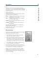
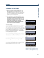
Stand-by Panel
The stand-by panel comprises an ON/OFF key and
three Light Emitting Diodes (LEDs):
1) The ‘POWER’ LED (green) lights up when the
main ON/OFF switch is set to ON.
2) The ‘ON’ LED (yellow) lights up when the main
ON/OFF (I/O) switch is set to ON (I) and the
ON/OFF key on the standby panel is set to ON
(pressing the key toggles between ON and OFF).
3) The ‘ERROR’ LED (red) lights up under certain
anomaly conditions (see Chapter 5).
The ON/OFF key on the panel is for use when you
want to turn off the power for a short period of time
or to stop the 333 or 334 Pump instantaneously.
When you want to turn off the power for a longer
period of time you should also switch off the power
using the main ON/OFF switch on the back panel of
the 333 or 334 Pump.
2-7
2
Rear Panel - Electrical Connectors
Description
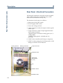
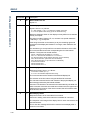
Rear Panel - Electrical Connectors
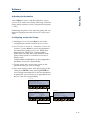
All electrical connections are made to the rear panel.
Also visible are the fan’s ventilation slots, which
must never be obstructed in any way.
The function of each item is as follows:
1 Main power ON/OFF switch.
2 Power supply cable socket.
3 Fuses and voltage selector.
4 14-pin connector socket for output contact signals
(relay type).
5 10-pin connector socket: 4 input signal channels
and 2 output channels:
1 digital output converted to analog (pin-9, 0-1 V,
configurable),
1 analog output (pin-10, 142-1000 mV, for
pressure).
6 GSIOC from controller (333 Pump or computer).
7 GSIOC to slave pump (333, 334 Pump and/or 30X
Pump) or Gilson 15X UV Detector.
14-pin Connector
GSIOC Connectors
10-pin Connector
Solvent Tray
Ventilation Slots
Rear Panel
Fixing Screw
(1 of 4)
Fan
ON/OFF Switch
Ventilation Slots
2-8
2
Description
333 Pump Control Components
For a 334 Pump, which has no other type of connector, a
pair of rotary switches for setting GSIOC ID number
setting and bit rate, replaces the left-most GSIOC socket.
Power Connector
The standard 3-pin connector accepts the power
supply cord supplied with your 333 or 334 Pump.
Power supply cord reference 500005 is for use in
France and Germany. Power supply cord reference
500006 is for use in USA and Canada. For other
countries, your local Gilson distributor can advise
you concerning the type of power connector to use.
Input/Output Signal Connectors (333
Pump)
The two sockets use the 14-pin and 10-pin connectors
supplied with your 333 Pump.
GSIOC Connectors
The 9-pin socket(s) accept standard GSIOC connectors.
The 333 Pump has two connectors (To Slave and From
Controller); the 334 Pump has one connector (From
Controller) and two switches for setting GSIOC
parameters.
Only use standard GSIOC
(Gilson Serial Input Output
Channel ) connectors.
2-9
2
Accessories
Description
Accessories
The standard accessories, supplied with the pump,
include plumbing items, tools, and electrical
connectors. Additional accessories, to be ordered
separately, include solvent valve block, solvent
degasser, an injection valve holder, extra plumbing
items, a column holder, electrical interfaces, and
cable kits. A shelf is available on which the pump
can be placed, allowing a 30X Pump to be placed
underneath.
A diskette is supplied containing Gilson’s Pump Data
Transfer Software, which enables the user to download
information from a 333 Pump to a Personal Computer
(PC).
Chapter 6 contains comprehensive lists of items
supplied as standard and additional accessories,
plus a list of recommended spare parts.
2-10
Installation
3
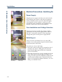
Your 333 or 334 Pump is delivered with its principal hydraulic components already
installed. You are advised to read this section, which contains important information
relating to both 333 and 334 Pumps; instructions are given for installing accessories,
where appropriate.
The software described in this Chapter is for users for whom a 333 Pump is the
controlling device. If your controlling device is a PC using (for example) Gilson’s
UniPoint Software, you should refer to the documentation relating to UniPoint.
The key steps, the minimum necessary to configure the pump(s) from a Master 333
Pump, are given in this Chapter – for full details of 333 software, refer to Chapter 4.
Here is a summary of the key steps:
1) Electrically connect the 333 or 334 Pump and any associated components (a detector,
other pumps, etc.), connect them to a suitable power supply, and switch-on all
components.
2) If control is from a Master 333 Pump, check or enter the configuration details using
the control panel on the 333 Pump. If control is from PC based software (e.g.
UniPoint) refer to the user’s guide for the controlling software.
3) Make the hydraulic connections to the 333 and 334 Pumps and their associated
components, then prime the pump(s); refer to Chapter 4.
You are then ready to enter or activate a Method Program using the control panel of the
333 Pump or from the controlling software.
For software information relating Gilson 15X Detectors, you are advised to refer to the
appropriate 15X Detector User’s Guide.
3-1
3
Electrical Connections - Switching-on
Installation
Electrical Connections - Switching On
Power Supply
Plug the power supply cord that you received with
the pump into the socket on the power receptacle
and to a suitable source of power. The actual plug
used depends on the country in which you will
operate the pump, should the one supplied not be
suitable, contact your Gilson representative.
Fuse Installation and Voltage Selection
There are no fuses to install, the pump is simply
connected to an AC power supply of 110/120 V or
220/240 V. Automatic selection of the operating
voltage takes place on the power supply board.
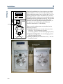
Switching-on
Gilson 333 and 334 Pumps have two ON/OFF
switches: one on the power receptacle and the other
at the front (above the LEDs).
To switch on a 333 or 334 Pump:
1) Press the switch on the power receptacle to the ‘I’
position; the ‘Power’ LED (green) on the front
panel should light-up; if it does not, check the
power connections.
333 Pump
3-2
334 Pump
2) Press the soft-touch key on the standby panel; the
‘ON’ LED (yellow) should light-up. With a 333
Pump, the start up screen should be visible on the
control panel’s display unit. The third indicator
light on a 334 Pump is labelled ‘Remote’; on a 333
Pump, it is labelled ‘Error’.
3
Installation
Electrical Connections - Communications
Electrical Connections Communications
You need to connect GSIOC cables between the
pumps, make connections to the detector, and make
any single-wire contact connections (for input/
output signals), which may be necessary for
communicating with other equipment.
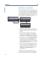
Contact Connections (Input & Output)
The input and output contact functions are shared
between two terminal blocks (14-pin and 10-pin)
situated on the pump’s back panel. The maximum
input voltage for any electrical device connected to
each input or output contact is 48 V.
Legend
NO = Normally Open
NC = Normally Closed
COM = Common
!"#
!"#
!"#
!"#
!"#
!"#
!"#
!"#
!"#
!"#
GSIOC
14-pin Connector
10-pin Connector
In order to connect signal wires to the terminal blocks,
you must first fit the appropriate connector (as
supplied in the standard accessories package).
The 14-pin connector fits the left-hand socket and
the 10-pin connector fits the right-hand socket.
After gently pushing each connectors into its socket,
you can connect wires to the appropriate terminal.
To connect a wire to the terminal you should strip back
the wire’s protective covering by 5 mm, undo the
terminal’s fixing screw, push the bared wire into the
corresponding hole in the terminal block, and then
tighten the fixing screw using a small screwdriver.
3-3
3
Electrical Connections - Communications
Installation
14-pin Connector
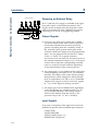
Powering an External Relay
A 12 V (500 mA) DC supply is available at the rightmost pair of pins of the left-hand terminal. This
supply can be switched manually from the control
panel or automatically from a Method Program by
connecting it to one of its neighboring outputs.
+
Power Contact
_
Output Signals
12 V Relay Coil
a) Four two-way relay-type outputs are available
via the left-hand socket. Each of these outputs is
electrically isolated from the others and from
ground. Switching from the ‘normally closed’ to
the ‘normally open’ position takes place under
software control (see Chapter 4) at pre-programmed
times. You can program these contacts to ‘Open’,
‘Close’, or ‘Pulse’, for a specific duration.
You connect one wire from the receiving device to
the common terminal of Output # 1 (2, 3, or 4) and a
second wire to either the corresponding ‘normally
open’ or ‘normally closed’ terminal, depending
on the requirements of the receiving device.
b) An output (pin # 9) is available on the right-hand
socket for feeding a recorder or a PC (via a suitable
interface). This output, which comes from the pump’s
microprocessor, can be configured to follow pressure,
flow, or composition (%A, %B, or %C). It is labelled
‘Digital’ but outputs a series of discrete signals
(0 - 1 V) via the digital-to-analog converter.
c) An output (pin # 10) is available on the right-hand
socket for feeding any suitable recorder or a PC
(via a suitable interface). This analog output,
which comes directly from the sensor, is for
pressure only (0.142 - 1 V for 0 - 60 MPa).
Input Signals
Four pairs of terminals of the right hand socket are
dedicated to specific software-related input functions:
START/END
PAUSE/RESUME
INPUT (WAIT) (Input # 1)
EMERGENCY (Input #2)
3-4
Installation
Except for WAIT, to activate one of these inputs, you
must change the state (close or open) of an output on
the external device.
START/END
An external relay contact, connected to this input,
may be used to start (OPEN ! CLOSE) and stop
(CLOSE ! OPEN) program.
PAUSE/RESUME
An external relay contact, connected to this input, may
be used to pause (OPEN ! CLOSE) and resume
(OPEN ! CLOSE) the Method Program currently
running. The pause may be configured (Chapter 4 )
with or without flow.
Electrical Connections - Communications
You connect a pair of wires from an output (e.g. relaytype) of the external device, to a pair of terminals,
for each of the functions that you want controlled
externally.
3
With flow means that pumping continues at the rate
and composition that existed at the time the pause
was initiated; when ‘resume’ is signaled the Method
Program continues from the same point.
INPUT (WAIT) (Input # 1)
An external relay contact, connected to this input, may
be used to signal to the Method Program currently
running the 333 Pump that the external equipment
(e.g. fraction collector, sampling injector) is ready.
EMERGENCY (Input #2)
Closing an external relay contact, connected to this
input, may be used to signal to the pump software
to start a Safety Program file (file 24).
3-5
3
Electrical Connections - Communications
Installation
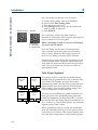
GSIOC Connections
When connecting more than two pieces of equipment
by GSIOC cable, the devices should be connected
linearly (i.e. in series) using shielded Y-type Gilson
cables (reference 500933). This type of cable has a
pair of female and male 9-pin D-connectors at one
end and a second female connector at the other.
You will need one less cable than the
number of devices being connected.
The first pair of devices in the chain
are connected using the female sockets
at either end of the cable. Then for the
third and subsequent devices, you
connect another cable between the
male socket on the GSIOC cable and
the appropriate socket on the next device. Thus, you
can ‘daisy-chain’ the pumps and other Gilson
equipment such as a 15X Detector.
A) A 334 (or a second 333 Pump) is being
controlled from a 333 Pump.
Plug one end of a GSIOC cable into the socket
marked ‘GSIOC FROM CONTROLLER’ on the
first pump (or detector) being controlled and plug
the other end into the socket marked ‘GSIOC TO
SLAVE’ on the controlling pump.
B) A 334 or 333 Pump is being controlled from a
computer.
Plug one end of a GSIOC cable into the socket
marked ‘GSIOC FROM CONTROLLER’ on the
first pump being controlled, plug the other end
into the GSIOC socket of a Gilson 506C System
Interface Module, and connect an RS232 cable
from the 506C to the computer. Alternatively you
can use a Gilson 605 RS232C-GSIOC Adapter.
Chapter 7 contains a description of the GSIOC cable,
connector pin-out information, a detailed description
of the GSIOC protocol, and a list of commands.
3-6
Installation
You must use the default values for a system where
a 333 Pump (Master) is controlling other devices
(slaves). By default the master pump is assigned ID
# 1, the slave elution pumps are assigned ID # 2, and
#3. The slave injection pump is assigned ID #4.
The GSIOC IDs may be changed where the pump(s)
are being controlled from a computer. In which case,
the configured IDs must correspond to those set
using the controlling software.
For each level, the GSIOC identification number (ID)
that you set must be unique for each item of Gilson
equipment.
For a 333 Pump, the ID (0-63) is configured as follows:
1) Switch on the pump; wait until initialized.
Electrical Connections - Communications
GSIOC ID
3
2) Press in turn: Edit, Config, Misc.
3) Key in the desired ID for the 333 Pump, then press
ENTER.
For a 334 Pump, the ID (0-9) is set mechanically
using the left-hand of the two selectors on the rear
panel (see Figure 3.5b).
For a 305 Pump, the ID (0-63) is configured using the
305 Pump’s keypad (see 305 Pump User’s Guide).
For a 306 Pump, the ID (0-63) is set mechanically
using switches on the rear panel (see 306 Pump
User’s Guide).
Bit Rate
You must use the default values for a system where
a 333 Pump (Master) is controlling other devices
(slaves).
When a 334 Pump is used as a slave to a 333 Pump,
the bit rate of the slave must be set to ‘External’.
Or, when the bit rates of the sending and receiving
devices need to be matched, you can set a specific
bit rate.
3-7
3
Electrical Connections - Communications
Installation
For a 333 Pump, the bit rate is set as follows:
1)
2)
3)
4)
GSIOC ID (0-9)
Switch on the pump; wait until initialized.
Press in turn: Edit, Config, Misc.
Press the down arrow key.
Press Change until you see the desired bit rate
(1200 to 19200 or External).
5) Press ENTER.
Bit Rate
For a 334 Pump, the bit rate (9600, 19200, or
External) is set mechanically using the right-hand of
the two selectors on the rear panel.
0 = External
1 = 9600 baud
2 = 19200 baud
When a 334 Pump is used as a slave to a 333 Pump,
you must select ‘External’.
For a 306 Pump, the bit rate is set mechanically
using switches on the rear panel (see 306 Pump
User’s Guide). When the 306 Pump is used as a
slave to a 333 Pump, you must select ‘External’.
External clock control should also be selected for all
pumps running under computer control. Internal is
used when the connected device does not provide a
clock source, in which case you have to select an
appropriate bit rate.
Twin Pump Systems
333 Pump
ID #1
To Slave
From
Controller
334 Pump
ID #2
From
Controller
333 Pump
ID #1
To Slave
From
Controller
334 Pump
ID #2
From
Controller
Two pumps may be connected in parallel thereby
doubling the programmed flow rate. In theory there
is no limit to the number of pumps that can be
connected in parallel, but the twin system with two
liquid streams is the most practical. The hydraulic
outlet tubings are connected together using a Teepiece to increase the overall flow rate.
To set-up 333 or 334 Pumps to operate in parallel, you
must give each of the paralleled pumps the same
GSIOC ID: the Master 333 Pump has an ID = 1 as does
its twin; the Slave 32X Pump and its twin both have an
ID = 2, and so on. The twinned pumps are connected
together using GSIOC cables.
When operating a twinned system, the commands
from the controlling device go to each pair of twins,
so that they act in unison. The twinned pumps must
have the same configuration as their master pumps.
3-8
3
Installation
Hydraulic Connections
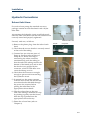
Hydraulic Connections
Solvent Inlet Lines
For each solvent pump, the standard accessory
package contains an inlet line fitted with a 20 µm
inlet filter.
Air entering the hydraulic circuit would adversely
affect the flow rate. Make sure that all connectors are
correctly seated and properly tightened.
Solvent Inlet Line
Proceed, with care, as follows:
Ferrule
1) Remove the plastic plug from the inlet of each
head.
Connector
2) Check that the reverse ferrule is correctly seated
at the end of the tubing.
3) Connect line A to inlet tee-piece of
Pump A, line B to inlet tee-piece of
Pump B, etc. When screwing or
unscrewing the white connector,
simultaneously push the tubing so
that the end of the tubing touches the
bottom of the female port and so that
the ferrule is not gripped by the
connector, which would other-wise
cause the tubing to twist.
Solvent Line
4) Check that the connectors are tight
enough to prevent air from entering
the hydraulic circuit.
5) In normal use, the pump operates
with the door closed, the solvent line
must therefore be threaded through
the port to the exterior, before
placing the inlet filter in the
appropriate solvent bottle.
6) Clip the solvent lines to the tray.
First, each tubing is attached to a clip
by pushing it gently into the fissure,
then the clip is pushed into the
appropriate slot on the tray.
Clip (Solvent Line)
Fissure
Clip (Rinsing Line)
7) Prime the solvent lines (refer to
Chapter 4).
3-9
3
Hydraulic Connections
Installation
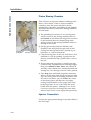
Piston Rinsing Chamber
If the solvent is an aqueous solution containing more
than 0.1 M of solute, which is solid in ambient
conditions, then the piston should be rinsed
continuously with water. A plumbing kit (ref: E66379)
should be installed for the piston rinsing chambers
of both heads.
1) The plumbing kit consists of: two rinsing lines,
which connect to the rinsing-chamber inlets at
the bottom of each head (the longer line connects
to the left head) and two shaped purge lines,
which connect to the rinsing-chamber outlets at
the top of each head.
Rinsing Line
(to Bottle)
Purge Line
(Rinsing Chamber)
2) Fill the glass bottle (reference E66386) with
distilled water and push the open end of each
rinsing line through the bottle’s pierced cap, to
between 1 to 2 cm of the bottom.
3) Clip the rinsing lines to the tray. Each line is first
attached to a clip by pushing it gently into the
fissure, and then the clip is pushed into a slot on
the tray.
4) Ensure that each purge line is closed (turn each
connector fully counterclockwise until finger tight),
then press Manual, Prime, Start. After about 20
seconds, water should have sufficiently filled the
rinsing line, even though some air is also present.
5) Press Stop; then undo both purge-line connectors.
Water will run from each purge line into the drip
tray; the rinsing lines and rinsing chambers will
fill with water. When you see bubble-free water
in the rinsing lines, and that air is no longer
exiting from the head via the purge lines, close
both purge lines. In use, water from the small
bottle rinses the piston - although it is a closed
circuit you may need to change the water from
time to time, and of course repeat this procedure.
Injector Connection
Connect the appropriate tubing to the outlet filter of
the 333 Pump.
3-10
3
Installation
Hydraulic Connections
Drip Tray
The removable drip-tray fitted to the pump
is supplied as standard.
The drip tray slots into the well at the bottom
of the pump. Installation consists of lifting
up the tray, fitting one end with a length of
tubing. The other end of the tubing goes to
the drain (or a suitable receptacle) via the
drain tubing exit port. Installation is
completed by replacing the drip tray.
Solvent Valve Block Installation
A solvent valve block is available as an
optional extra; it may be used to test the
effectiveness of different solvents (or to
perform rinsing, cleaning, and
conditioning). The liquids are routed via
suitable tubing to the valve block, which
performs all of the required switching
functions, at low pressure, under software
control.
Exit Port
Drain Tubing
This item would be pre-installed by your Gilson
representative. The solvent valve block replaces the
plate that can be seen just above the drip tray.
Pump Head Installation
The pump heads are pre-installed. However, for
routine servicing, you will need to remove the pump
heads (refer to Chapter 5).
3-11
3
Accessories
Installation
Accessories
Additional accessories may be obtained from Gilson,
these are: a degasser, a column holder, a holder for a
manual injection valve, and a shelf to enable you to
stack 333, 334 Pumps, and 15X Detectors. This shelf
is designed to support the weight of the pump and
solvent bottles. Assembly consists of using the
supplied screws to attach four legs to the metallic tray.
Space is available between the legs for a detector or
a 30X Pump.
The solvent-bottle tray, which is supplied as a
standard accessory, is easily fitted to both 333 and
334 Pumps.
Degasser
Please refer to the User’s Guide of the Gilson 864
degasser.
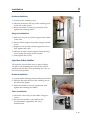
Column Holder
The column holder attaches to the left side of the pump.
Three pairs of column support, fitted with clips for
different diameter columns, are provided in the kit.
Column Support
Retaining Knob
Column Support
Knurled Screw
3-12
Retaining Stud
3
Installation
Retaining
Stud
1) Loosely fit the retaining stud.
2) Slide the studs into the tops of the retaining slots
at the side of the pump.
Accessories
Holder Installation
3) When the holder is correctly positioned, fully
tighten the retaining knobs.
Support Installation
1) Push one of a pair of column supports into either
of the slots.
2) Fix the column support in position using a knurled
screw.
Retaining Slot
3) Repeat for the second column support but don’t
fully tighten the screw.
4) Slide the second column support along the long
slot to match the length of the column.
5) Fully tighten the screws.
Injection Valve Holder
The injection valve holder has two pairs of holes,
one pair is for mounting the valve in the vertical
position and the other is for mounting the valve in
the horizontal position.
Holder Installation
1) Loosely fit the retaining studs to either pair of holes.
2) Slide the feet into the top of the retaining slot at
the side of the pump.
3) When the holder is securely positioned, fully
tighten the retaining-feet knobs.
Valve Installation
1) Secure the valve body to the holder using two
screws.
2) Fit the valve handle, as described in the
documentation supplied by the valve
manufacturer.
3-13
3
Accessories
Installation
3-14
Solvent-bottle Tray
The figure shows the tray being fitted to a 333 Pump.
For a 334 Pump, the tray simply sits on top of the
pump, its feet resting in the special recesses.
3
Installation
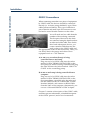
Horizontal Configuration
In normal use the pumps may be placed side-by-side
(see “Configuration Example 1”). The 333 Pump
(Solvent A), at the left, is fitted with PPMM and
outlet filter. To connect to the 334 Pump at the right,
you require a special shaped tubing (E66360),
available as a standard accessory. Solvent B is routed
via the outlet tee-piece of 334 Pump, to an inlet on
the PPMM of the 333 Pump, where the two solvents
are mixed at high pressure.
In order to maximize the
performance of your 333-334
Pumping System, it is important
that you use only the special
shaped tubing to link the two
pumps.
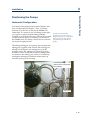
Positioning the Pumps
Positioning the Pumps
The tubing linking the two pumps goes through the
tubing port, together with solvent and rinsing port
tubings. In the figures, the tubing-port is in the
position where the tubings are “locked” in place.
To make it easy to install and to remove tubings, there
is a fissure in the tubing port, which is accessed by
rotating the tubing port until the fissure lines up
with the opening in its housing.
Connecting Tubing
(Side-by-side Configuration
Ref. E66360)
Tubing Port
3-15
3
Positioning the Pumps
Installation
Vertical Stacking
Connecting Tubing
(Vertical Stacking
Ref. E66451)
In order to maximize the
performance of your 333-334
Pumping System, it is important
that you use only the special
shaped tubing to link the two
pumps.
3-16
Where bench space is at a premium, the pumps may
be stacked one on top of the other. The 333 Pump
(Solvent A), at the top, is fitted with PPMM and
outlet filter. To connect to the 334 Pump at the bottom,
you require a special shaped tubing (E66451),
available as an additional accessory. Solvent B is
routed via the outlet tee-piece of 334 Pump, to an
inlet on the PPMM of the 333 Pump, where the two
solvents are mixed at high pressure.
The tubing linking the two pumps goes through the
tubing port, together with solvent and rinsing port
tubings. In the figures, the tubing-port is in the
position where the tubings are “locked” in place.
To make it easy to install and to remove tubings, there
is a fissure in the tubing port, which is accessed by
rotating the tubing port until the fissure lines up
with the opening in its housing.
3
Installation
Setting-up
Setting-up
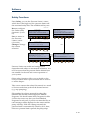
Basic Elements
Take care when you are reconfiguring a 333 Pump,
and have previously created Method Program files,
you will probably need to modify these files, if they
are to work correctly with the new configuration
(types of solvent, associated pumps, etc.).
A 333 Pump may be used alone, or as the master
pump controlling up to two other solvent pumps
(333 or 334). It may also be used to command an
injection pump (30X). 334 Pumps are for use as extra
solvent pumps always connected hydraulically to
the PPMM of a 333 Pump.
S c reen
P u mp f ile: 12
Lo op: 1
. 012 m l/ m in
15. 0 % A
E di t
Man ual R un
Outlet
St op
Outlet Tee
PPMM
Heads
OF
Inlet Tee
O u tle t
O u tle t Te e
Heads
In le t Te e
S o lv e n t In le t
( v i a 2 0 m filte r )
Solvent Inlet
(via 20 m filter)
Pump ID #2 or 3
Key:
PPMM = See text below
OF = Outlet Filter
T = Tee-piece
P um p ID #1
3-17
3
Setting-up
Installation
S c re e n
P u mp f i le : 1 2
Loop: 1
.0 1 2 m l /m in
1 5 .0 % A
E dit
Ma n ua l R un
St op
PPMM
OF
Outlet
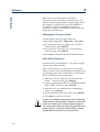
Three typical configurations are described in the
following Sections:
Outlet Tee
1) Binary Gradient (or an isocratic mixture of two
solvents): 333-334 Pumping System.
(or ternary gradient: 333-334-334 Pumping System ).
Heads
Inlet Tee
A2
A1
A3
SVB
Extended capabilities for solvent selection are offered
by the addition of a Solvent Valve Block (SVB) to any
of the configured pumps (A1 to A4, B1 to B4, C1 to C4).
Figure opposite shows how the addition of a Solvent
Valve Block (SVB) could be used to test the effectiveness
of different solvents, selected successively. The solvents
are routed via suitable tubing to the SVB, which
performs all of the required switching functions, at
low pressure (no mixing takes place between
solvents connected to a valve block).
A4
2) Injection Configuration: 333-334 Pumping System
and 30X injection pump.
3) Binary Gradient (controlled from a PC): 333-334
Pumping System.
Connecting Tubing
(Ref. E66360)
3-18
Installation
3
Setting-up
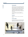
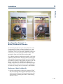
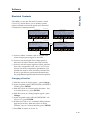
Configuration Example 1:
Binary Gradient or Isocratic
A 333 Pump may be set-up to control the flow and
composition on a time variant (gradient) or a time
invariant (isocratic) basis, when associated with a
334 Pump. Thus, you can pump gradients using two
solvents, or you can pump in isocratic mode, after
mixing (A from one pump, B from the other).
For a binary-gradient configuration, install a 333 Pump
(Master) at the left and a 334 Pump (Slave) at the right,
although the slave pump could be a second 333 Pump.
Solvent B is routed via the outlet Tee-piece of the 334
Pump to an inlet on the PPMM of the Master 333
Pump, where the two solvents are combined at high
pressure. When three solvents are to be combined, a
second slave pump can be connected to the PPMM.
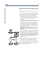
Setting-up - What You Must Do
1) Switch on the pump(s); check and set their GSIOC
IDs, the start-up screen appears (briefly, Screen 0);
then make the electrical connections between the
instruments, including the GSIOC cable linking
Master to Slave.
3-19
3
Setting-up
Installation
S c re e n 1
P u m p file : [- - ]
.0 0 0 m l/m in
0% A
0% B
0.0 M P a
M anual
Ed it
Screen 2
P u m p c on tro l
R u n file :
[--]
E dit file:
[--]
W a tc h file : [--]
File
C re ate C on fig
W atc h G LP
S creen 50
C o n fig u ra tio n
M o d e l: 3 3 3
In je c tio n fro m p u m p : N O
C o n tro lle d p u m p : 3 3 X (2 )
M a x im u m n u m b e r o f s o lv e n t s : T W O
C o n fig u ra tio n
M o d e l: 3 3 3
In je c tio n fro m p u m p : N O
M a x im u m n u m b e r o f s o lv e n ts : O N E
S afe ty
I/O
M is c C h an ge H ard
S afe ty
Hyd
I/O
M isc C ha n ge H ard
Hyd
ESC
S creen 78
H ardware
M od el: 3 33
C o n tro lle d p u m p s fo r:
E x t r a s o lv e n t
E x t r a s o lv e n t
Injection
C o n f ig u r a ti o n
ENTER
( id 2 ) : N o n e
( id 3 ) : N o n e
( id 4 ) : N o n e
Change
Scan
In the Figures given in this
Chapter: The key to push is
indicated by the lighter color
soft-key; follow the path
indicated by the arrows. When
you should push other control
panel keys (e.g. ENTER) these
are indicated in bold at the
appropriate point.
3-20
H a rd w a re
M o d e l: 3 3 3
C o n tro lle d p u m p s fo r:
E x tra s o lv e n t
E x tra s o lv e n t
In je c tio n
C o n fig u ra tio n
(id 2 ): 3 3 X
(id 3 ): N o n e
(id 4 ): N o n e
Change
Scan
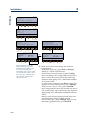
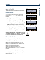
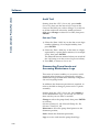
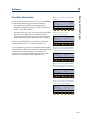
2) Check and if necessary change the software
configuration:
- at the Run Screen (1), press Edit, or Pump if
linked to a Gilson 15X Detector.
- at the Pump Control Screen (2) press Config.
- for a new pump, the Configuration Screen (50)
shows 333 as the model, H3 as the head type,
‘Injection from pump: NO’, ‘Maximum number
of solvents: ONE’.
- to add solvent pump B, press Hard; Screen (78)
appears, at ‘Extra solvent (id 2)’ press Change,
until you see ‘334’ (or ‘333’), press ENTER.
- the Configuration Screen (50) should now show
333 as the model, H3 as the head type, ‘Injection
from pump: NO’, ‘Maximum number of solvents:
TWO’.
- then for each solvent pump (if head type does
not match those fitted to either pump),
- select ‘Head type’, press Change, until you see
the head type fitted (H3), press ENTER.
3
Installation
Setting-up
S c re e n
P u mp f i le : 1 2
Loop: 1
.0 1 2 m l /m in
1 5 .0 % A
E dit
Ma n ua l R u n
St op
PPMM
OF
Outlet
Outlet
Outlet Tee
Outlet Tee
Heads
Inlet Tee
Solvent A
Pump ID #1
Heads
Inlet Tee
Solvent B
Pump ID #2 or 3
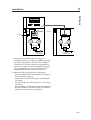
Alternatively, provided the first step (1) is
completed correctly, you may press Scan to identify
any connected pumps, which are then added to
Screen 78 next to their currently configured IDs.
You are now ready to create your Method Program
file(s). Optionally, you can modify advanced
configuration features (refer to Chapter 4).
3) Make the following hydraulic connections:
- from the Outlet Filter of the Master 333 Pump to
the downstream injector.
- solvent line A to the inlet Tee-piece on the Master
333 Pump,
- solvent line B to the inlet Tee-piece on the Slave
334 Pump,
- special tubing (ref: E66360) from the Tee-piece of
the Slave Pump to the inlet on the 333’s PPMM.
- prime the system (refer to Chapter 4).
3-21
3
Setting-up
Installation
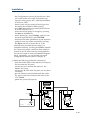
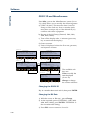
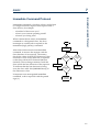
Configuration Example 2:
Solvent Mixing and Injection
A 333 Pump may be set-up to control the flow and
composition on a time variant (gradient) or a time
invariant (isocratic) basis; to carry out sample injection,
a 30X Pump must also be associated with the 333
Pump. In this case, the 333 Pump controls the injection
pump, flow, and composition. Solvent B is routed via a
Tee-piece to an inlet on the PPMM of the Master 333
Pump, where the two solvents are combined at high
pressure.
Setting-up – What You Must Do
1) Switch on the pump(s); check and set their GSIOC
IDs, the start-up screen appears (briefly, Screen 0);
then make the electrical connections between the
instruments.
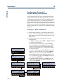
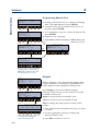
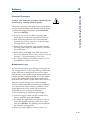
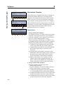
2) Check and if necessary change the software
configuration:
- at the Run Screen (1), press Edit, or Pump if linked
to a Gilson 15X Detector.
- at the Pump Control Screen (2) press Config.
- for a new pump, the Configuration Screen (50)
shows 333 as the model, H3 as the head type,
‘Injection from pump: NO’, ‘Maximum number
of solvents: ONE’.
- to add solvent pump B, press Hard; Screen (78)
appears, at ‘Extra solvent (id 2)’ press Change,
until you see ‘334’ (or ‘333’), press ENTER.
- to add the injection pump, press the down arrow
key; at ‘Injection (id 4)’ press Change, until you
see ‘30X’, press ENTER.
- to enable sample injection, press ESC, then at
configuration Screen (50), press Change, select
‘YES’, press ENTER.
S c re e n 1
P u m p f il e : [ - - ]
.0 0 0 m l/ m in
0% A
0% B
0.0 M P a
Manual
Edit
Sc reen 2
P u m p c o n tro l
R u n file :
[--]
E dit file :
[--]
W a tch file : [--]
File
C re a te C o n fig
W atch G L P
S c re e n 50
C o n f ig u r a ti o n
M odel: 333
In j e c t io n f r o m p u m p : N O
C o n t r o ll e d p u m p : 3 3 X ( 2 ) 3 0 X / 5 ( 4 )
M a x im u m n u m b e r o f so lve n ts : T W O
C o n f ig u r a ti o n
M o d e l: 3 3 3
In je c tio n f ro m p u m p : N O
M a x im u m n u m b e r o f so lv e n ts : T W O
Sa fety
I/O
M isc C ha nge H ard
Safety
Hyd
I/O
M isc C hang e H ard
ENTER
Hyd
ESC
S creen 78
H ard w a re
M o d e l: 3 3 3
C o n tro lle d p u m ps fo r:
E x tra so lv e n t
E x tra so lv e n t
In je c tio n
C o n fig u ra tio n
( id 2 ): 3 3 X
( id 3 ): N o n e
( id 4 ): N o n e
Change
3-22
ENTER
Scan
H a rd w a re
M odel: 333
C o n tr o ll e d p u m p s fo r :
E xtra solvent
E x tra so lve n t
I n j e c t io n
C o n fig u r a tio n
(id 2 ): 3 3 X
(id 3 ): N o n e
(id 4 ): 3 0 X
Change
Scan
C o n fig u ra tio n
M o d e l: 3 3 3
In je c tio n fro m p u m p : Y E S
C o n tro lle d p u m p : 3 3 X (2 ) 3 0 X /5 (4 )
M a xim um nu m ber o f solvents: TW O
S afety
I/ O
M is c C hang e H ard
Hyd
3
Installation
Setting-up
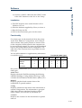
- the Configuration Screen (50) should now show
333 as the model, H3 or H2 as the head type,
‘Injection from pump: YES’, ‘Maximum number
of solvents: TWO’.
- then for each solvent pump (if head type does
not match those fitted to either pump),
- press Hyd, then at the next screen (90 for Solvent
A, 91 for Solvent B, etc.) :
- select the solvent pump to change by pressing
the Next or the Prev key,
- select ‘Head type’, press Change, until you see
the head type fitted (H3), press ENTER.
- head size and other parameters for the injection
pump (Screen 94) can be accessed by pressing
the Inject soft-key at Screen 90, 91, or 92.
Alternatively, provided the first step (1) is
completed correctly, you may press Scan to identify
any connected pumps, which are then added to
Screen 78 next to their currently configured IDs.
You are now ready to create your Method Program
file(s). Optionally, you can modify advanced
configuration features (refer to Chapter 4).
3) Make the following hydraulic connections:
- from the Outlet Filter of the Master 333 Pump to
the downstream Tee-piece.
- solvent line A to the inlet Tee-piece on the
Master 333 Pump,
- solvent line B to the inlet Tee-piece on the Slave
334 Pump,
- special connector (ref: E66360) from the outlet
Tee-piece of the Slave Pump to the inlet of the
333’s PPMM.
- prime the system (Chapter 4).
S c re e n
P u m p fil e : 1 2
Loop: 1
.0 1 2 m l /m in
1 5 .0 % A
E d it
M a n ua l R un
S to p
PPMM
OF
O u t le t
O u t le t
Te e - p ie c e
O u t le t Te e
O u t le t Te e
30X Pum p
H eads
Heads
In le t Te e
P um p ID # 4
I n le t Te e
S a m p le
S o lv e n t A
P um p ID # 1
S o lv e n t B
Pu m p ID #2 or 3
3-23
3
Setting-up
Installation
Configuration Example 3: 333-334
Pumping System with Control from a PC
The 333 Pump (Solvent A), at the left, is fitted with a
PPMM. To connect to the 334 Pump at the right, you
require a special shaped tubing (ref: E66360). Solvent
B is routed via the outlet tee-piece of 334 Pump, to
an inlet on the PPMM of the 333 Pump, where the
two solvents are mixed at high pressure.
The 333 Pump can be stacked on top of the 334
Pump: in which case you must use the connecting
tubing for vertical stacking, reference E66451.
Sc ree n
Pum p f ile: 12
L oop: 1
.01 2 m l/ m in
1 5.0 % A
E dit
Ma nua l R un
Stop
PPMM
OF
Outlet
Outlet
Outlet Tee
Outlet Tee
Heads
Heads
Inlet Tee
Inlet Tee
Solvent A
Pump ID #1
Solvent B
Pump ID #2 or 3
GSIOC Cable
Gilson Interface 506C
Setting-up – What You Must Do
1) The two pumps must have different GSIOC IDs
(except if working in parallel); normally 1 and 2.
Set their GSIOC IDs using the rotary switches on
their rear panel.
2) Make the electrical connections between the PC,
systems interface module. The two female
connectors on the GSIOC cable are plugged into
the “FROM CONTROLLER” sockets on the pumps
and a second cable connects from the male socket
to the next unit in the line (e.g. 15X Detector) or
the systems interface module (Gilson 506C).
3) Switch on the pumps.
4) Use the controlling software (UniPoint) to
configure and program the pumps.
3-24
Installation
Setting-up
5) Make the following hydraulic connections:
- from the Outlet Filter of the 333 Pump to the
downstream injector.
- solvent line A to the inlet tee-piece on 333 Pump,
- solvent line B to the inlet tee-piece on 334 Pump,
- special tubing (ref:E66360) from the outlet tee-piece
of the 334 Pump to the inlet of the 333’s PPMM.
- prime the system.
3
3-25
Installation
3-26
3
Software
4
4-1
4
Using the Control Panel
Software
Using the Control Panel
The control panel consists of a display unit and a
keypad.
Display Unit
The 40-character, 8-line display
unit is used to show time
related events, flow rate,
solvent composition, in-run
information, and so on. The
bottom line of the display unit
is for labeling six variablefunction soft-keys.
Keypad
The soft-keys are identified by the six evenly spaced
circles just below the display unit.
Pressing a soft-key selects the function displayed
directly above it, for example: Edit, Manual, and Run.
Descriptions of these and all other soft-key labels are
given later in this Chapter. Where a soft-key may
take an alternative label, the alternative is shown in
between parenthesis; for example, Edit (Pump).
In addition to the variable-function soft-keys, there
are fixed function keys as follows:
Four arrow keys:
to navigate around the screen,
Eleven numeric keys (0 to 9, and .):
to enter values (for predefined parameters),
ENTER to enter a value or option into memory,
HELP
For the screens that illustrate this
Chapter, the soft-key to press is
indicated by the lighter color
soft-key; follow the path
indicated by the arrows. When
you should press other control
panel keys (e.g. ENTER) these
are indicated in bold at the
appropriate point.
4-2
for detailed help messages (including the
screen number).
CLEAR to cancel a value before it is entered into the
memory,
ESC
to change from a software level to a higher
one.
4
Software
Switching On the Pump
Switching On the Pump
1) The power supply switch, located on the rear
panel, must be set to the ON position (I); the
POWER LED comes on. Next, press the ON/OFF
switch on the standby panel at the front of the
pump; the ON LED illuminates.
2) After switching on a 333 Pump, the display shows
Screen 0 for one second whilst initialization takes
place. During which time a message indicating
the software version is displayed, then you see
the ready-to-run screen (Screen 1). This dynamic
screen varies according to the associated
equipment, whether a Method Program exists,
and according to in-run information.
Screen 0
S creen
3 3 3 - H 3 V e rs io n 1 . 0 0
I n iti a l iz in g .. .
Wait for 1 second …
Screen 1
Screen 1 looks like this, the first time you switch on,
when a Gilson Model 15X Detector is associated
with the pump. In this case the top line is dedicated
to showing the output signal and wavelength of that
detector. Dual wavelength detectors (155 & 156)
have both output signals displayed. The Detect key
accesses the detector functions.
Screen 1 looks like this, the first time you switch on,
when no Method Program file has yet been run and
when there is no associated 15X Detector.
- 0.0 03 5 0 A U a t 2 5 4 n m
P u m p file : 11
. 0 0 0 m l/ m in
0% A 0% B
D e te c t o r f ile : 1
0 .0 M P a
Pum p Detect M anual
Zero
Screen 1
P u m p file : [--]
. 0 0 0 m l/ m in
0%A 0% B
E dit
0.0 M Pa
M anual
Screen 1
Screen 1 looks like this, when you switch on, and a
Method Program file has been run previously.
S cre en
P u m p file : 1 2
Loop: 1
.0 0 0 m l/m in
0%A
E d it
1 .0 0 m in
0.0 M Pa
0% B
M anual R un
Screen 1
Screen 1 may look like this where, at the end of the
Method Program, the flow rate is > zero.
S cre en
P u m p file : 1 2
Loop: 1
.4 9 8 m l/m in
9 5 .0 % A
5.0 % B
E d it
M anual R un
4 .00 m in
0.1 M Pa
Stop
Convention for pump file numbers:
Pump file: [- -] = no file selected.
Pump file: [xx] = file xx is selected but is empty.
Pump file: xx = file contains at least one event
(Method Program or Safety File)
4-3
4
Priming
Software
Priming
The following steps must be completed before
operating the pump, under the control of the pump’s
software, by a computer based program, or manually
from the pump’s control panel.
1) Make the electrical and hydraulic connections to
the pump(s).
2) Connect the power and switch on the pump(s).
3) Prime the hydraulics, initialize and run-in the
piston seals (if new).
Hydraulic Priming
This is an essential step, which must be carried out
before operating a 333 Pump or 334 Pump.
1) If one or more pumps are controlled from a 333
Pump, the additional pump(s) must be declared
in the configuration (see “Configuring”).
2) Fill the solvent bottles with (degassed) HPLCgrade solvents and immerse the filters of the
pumps’ inlet tubings in these bottles.
3) Switch the valve to the purge position.
4) Press Manual, Prime, then Start for the pump head
that is to be primed (see “Manual Operations” ).
If after two minutes, solvent does not flow from
the purge valve’s outlet, check that the valve is in
the open position, then remove the tubing and
attach a syringe to the purge valve’s outlet, using
a suitable adapter.
5) Draw solvent into the syringe while continuing to
pump. When solvent appears in the syringe,
press Stop, to cease pumping.
6) Reconnect the tubing and continue priming for as
long as is necessary. No bubbles should be present
in the solvent flowing through the tubing. Press
Stop, to cease pumping.
7) Repeat the procedure for the other pumps in the
system.
4-4
Software
B) Ensure that the purge valve is fitted with a drain
tube, before priming the pump.
Priming
A) Running a pump head dry, for more than a short
time, will damage the piston seal.
4
C) During priming the low pressure limit is inactive,
the high pressure limit is automatically set to 3
MPa, to protect the column if you forget to open
the purge valve, in which case the screen displays
the following message, ‘Open Purge Valve’.
After Priming
1) Use the GLP function Seal to initialize the piston
seals.
2) After completing the installation and configuration
processes, you can create and run Method
Programs.
4-5
4
Configuring
Software
Configuring
Introduction
To configure, you enter descriptions of your pumping
system’s hardware. You verify, and where necessary,
change the configuration (refer to “Hardware
Configuration” and “Hydraulic Configuration” for
detailed information.
As a minimum, you must correctly describe and
identify (GSIOC) all pumps: the controlling pump
(Master) and those it controls (Slaves).
Additionally, you may configure the input/output
signal parameters, safety functions, and fine tune
the hydraulic parameters (refill time, inlet pressure,
compressibility, etc.).
Procedure
Switch on the 333 Pump, then (after initialization)
you see the ready-to-run screen (Screen 1). You will
see the following soft-keys at one time or another:
Pump (Edit) to access pump operations,
Detect to access an associated detector,
Manual to prime and operate manually,
Run to run the current Method Program file,
Pause to interrupt the Method Program,
Resume to restart a paused Method Program,
End to stop a Method Program,
Stop to stop pumping and Method Program (if
running),
Zero to zero the detector signal (if associated).
4-6
4
Software
File to access the file management operations,
Screen 1
P u m p file : [--]
.0 0 0 m l/m in
0.0% A 0.0 % B
0.0 M P a
Manual
Edit
Edit (Create or View) to modify an existing
Method Program file,
Create (Edit or View) to enter a new Method
Program file,
View (Edit or Create) to read (only) an existing
Method Program file,
Sc re e n 2
P u m p c o n tr o l
R u n file :
[--]
E d it f il e :
[--]
W a tc h file : [-- ]
File
C re a t e C o n f ig
Config to enter configuration parameters,
GLP to access audit, maintenance, run-in and test
functions for a 333 pump,
Watch to obtain post-run information.
2) Press: Config, you see the ‘Configuration’ screen
(Screen 50), which indicates the model and head
type for the Master pump and any pumps under
its control. Inside this mainly descriptive screen,
you can activate an associated sample injection
pump. The available soft-keys are:
Safety to access high and low pressure limits,
restart and malfunction options,
I/O to access specific Input/Output functions
(pulse length, output signal type, etc.),
Configuring
1) Press: Pump (Edit), you see the ‘Pump Control’
screen (Screen 2) you will see the following softkeys at one time or another:
W atch G L P
S c re e n 5 0
C o n fig u r a tio n
M o d e l: 3 3 3 -H 3
I n je c t io n f ro m p u m p : N O
M a x im u m n u m b e r o f s o lv e n ts : O N E
S afety
I/O
M isc C h ang e H ard
Hyd
(1) The top-line of the in-run
screen is reserved for a Model
15X detector, if associated
with a 333 Pump (not shown
in most of the Figures given
in this Chapter).
(2) For the functions accessible
from the ‘Detect’ soft-key,
you should refer to the user’s
guide for the relevant
detector.
Misc for GSIOC id, bit rate, units, display
contrast, screen saver, beeper ON/OFF.
Hard to change the pump model and identify any
controlled pumps,
Hyd to access hydraulic parameters, such as Inlet
Pressure and Compressibility.
When setting-up a new system you should proceed
by reviewing, and changing where necessary, these
items in the following order: Hard, Hyd, Safety, I/O,
and Misc.
4-7
4
Configuring
Software
Hardware Configuration
Starting at Screen 50, which shows the current
configuration, press Hard, you see the ‘Hardware
Configuration’ screen (Screen 78). The available softkeys are:
Change to change the current selection,
Scan to check the GSIOC bus for suitably connected
and viable pumps.
S creen 50
C o n fig u ra t io n
M od e l: 3 3 3-H 3
C o n tr o lle d p u m p : 3 3 X
In jection from pu m p: N O
M a x im u m nu m b e r o f s o lv e n ts : T W O
C o n fig u ra t io n
M o d el: 3 33 -H 3
In je c tio n fr o m p u m p : N O
M a x im u m n u m b e r o f s o lv e n ts: O N E
Sa fe ty
I/O
M is c C han ge H ard
S a fe t y
Hyd
I/O
M isc C ha n ge Ha rd
Hyd
ESC
S creen 78
H a r d w a re C o n fig u r a tio n
M o d e l: 3 3 3 - H 3
C o n tr o lle d p u m p s fo r:
E x t r a s o lv e n t ( id 2 ) : N O N E
ENTER
In je c tio n ( id 4 ) : N O N E
Change
Scan
H a r d w a r e C o n fig u r a tio n
M o d e l: 3 3 3 - H 3
C o n tr o lle d p u m p s fo r :
E xtr a s o lv e n t (id 2 ): 3 3X
E xtr a s o lv e n t (id 3 ): N O N E
In je c tio n (id 4 ): N O N E
Change
Scan
A Master 333 Pump can control one or two additional
solvent pump (Slaves) and an injection pump. The
controlled pumps must be assigned as follows:
‘Extra solvent (id 2)’ can be a 333 Pump or a 334 Pump,
‘Extra solvent (id 3)’ can be a 333 Pump or a 334 Pump.
‘Injection (id 4)’ must be a 30X Pump, if an injection
(sample) pump is present.
Adding a Solvent Pump
1) Use the arrow keys to move the cursor to ‘Extra
solvent (id 2)’, if you want to add an extra pump
for solvent B, and then to ‘Extra solvent (id 3)’,
for solvent C. If you only have two solvent pumps,
the second pump must be configured as solvent B.
’Scan’ checks the ids of the
controlled pumps, which must be
connected via GSIOC, and
switched on. Scan does not
validate the pump’s
configuration - you must ensure
that you describe the pump
correctly to the software.
4-8
2) Press Change until you find the required option
(333 or 334) then press ENTER, or press Scan to
scan the GSIOC bus for devices connected to the
pump.
3) Press ESC to return to Screen 50; check that all
pumps are listed correctly, including the head
type (for 30X pumps):
e.g. 33X (for 333 and 334), 30X-10 (for 305, 306,
307, and 308), or NONE.
Software
1) Use the arrow keys to move the cursor to ‘Injection
(id 4)’ to assign a 30X Pump for injecting samples.
2) Press Change to select 30X, then press ENTER, or
press Scan to scan the GSIOC bus for devices
connected to the 333 Pump.
Configuring
Adding an Injection Pump
4
3) Press ESC to return to Screen 50; check that the
injection pump is listed correctly; the format for a
30X Pump is ‘30X-abc’, where ‘abc’ is the configured
pump-head size (see Hydraulic Configuration).
You must confirm the assignment as follows: with
the cursor at ‘Injection from pump: NO’ press
Change until you see ‘YES’, then press ENTER.
Removing a Pump
1) Use the arrow keys to move the cursor to ‘Extra
solvent (id 2)’, if you want to remove the extra
pump for solvent B.
2) Press Change until you find the required option
(NONE) then press ENTER.
3) With the cursor at the appropriate line, repeat for
‘Extra solvent (id 3)’ or repeat for ‘Injection (id 4)’.
Press ESC to return to Screen 50.
Hydraulic Configuration
Press Hyd to access the ‘Hydraulic Configuration’
screens for each of the solvent pumps defined earlier.
The first (Screen 90) is for Pump 1 (Solvent A), the
second (Screen 91) is for Pump 2 (Solvent B), and the
third (Screen 92) is for Pump 3 (Solvent C). You move
between screens using the Next/Prev keys. The
sample pump is accessed using the Inject soft key.
Each screen enables you to select the head type,
define a Solvent Valve Block (SVB), and name a
solvent for each of its four channels, or to specify a
value for compressibility for each.
The available soft-keys are:
Next to go the next screen,
Prev to go to the previous screen,
Adjust to configure advanced hydraulic functions,
4-9
4
Configuring
Software
Change to change the current selection,
Inject to configure the sample injection pump.
Configuring a Solvent Pump
For each solvent pump:
1) Check that the head corresponds to the type fitted;
press Change to modify the type configured,
press ENTER to confirm. For 333 and 334 Pumps
the head type must be H3.
2) For each pump fitted with a SVB: use the arrow
keys to select ‘Solvent valve block: NONE’; press
Change to select a solvent channel (A1 to A4, B1
to B4, C1 to C4), press ENTER to confirm. If no
SVB is fitted, you can skip this step, in which case
you see only one solvent channel per pump (A, B,
or C) for each of which you may select the solvent
type and enter a value for Inlet Pressure.
3) For each solvent channel (A or A1 to A4, B or B1 to
B4, C or C1 to C4), use the arrow keys to select a
solvent name (or enter a value for compressibility),
press Change to select another solvent, press
ENTER to confirm. For more, see ‘Named
Solvents - Compressibility’ (below) and for full
details, refer to Chapter 6.
4) Optionally, for each single-solvent channel pump,
you may key in a value for Inlet Pressure (0-50
MPa); that is the pressure at the inlet to the pump
head. This option is not offered when you have
configured an SVB.
S cre e n 5 0
C o n f ig u r a t io n
M o d e l: 3 3 3 -H 3
In je c tio n fro m p u m p : N O
C o n tr o l le d p u m p : 3 3 X
M a x im u m n u m b e r o f s o lv e n ts : T W O
S afety
I/O
M isc Chan g e Hard
Hyd
Screen 90
S cre e n 9 1
S o lv e n t A
H ead type: H 3
S o lv e n t v a lv e b lo c k : N O N E
S o lve n t A : W AT E R
In le t p r e s s u re : 0 .0 M P a
Next
In je c t C h a n g e
Ad just
Solvent B
Head type: H 3
S o lv e n t v a lv e b lo c k : B 1 s e le c te d
B1 HEXANE
B 2 W AT E R
B 3 W AT E R
B 4 W AT E R
P r e v In je c t C h a n g e
S creen 60
A d ju s t h y d ra u lic s
I n it ia l i z e p i s t o n b e f o r e in j e c t io n : N O
Change
4-10
A dju st
4
Software
Configuring
Adjusting the Hydraulics
Press Adjust to access ‘Adjust Hydraulics’ screen
(Screen 60) in order to access the following: ‘Initialize
piston before injection’ (only if ‘Injection from pump
‘= YES).
Initializing the piston of the injection pump 30X can
improve injection precision at low flow rates (set to
YES).
Configuring an Injection Pump
1) Starting at Screen 50, press Hyd to access the
configuration screen for solvent A (Screen 90).
2) At Screen 90 (or Screen 91 - solvent B, or Screen 92 solvent C), press Inject to access the parameters
for the injection pump (Screen 94): ‘Refill Time,
Inlet Pressure, Head Type, Compressibility.
Refill Time (125-1000 ms) is the duration of the
piston return stroke. If cavitation occurs use a
higher value.
Compressibility (0-2000 Mbar-1) is the compensation
parameter for solvent compressibility.
3) Use the arrow keys to move the cursor to the
parameter that you want to change.
4) Key in the desired value, then after keying in the
value press ENTER. After pressing ENTER the
cursor jumps automatically to the next parameter.
In particular, you must key in an appropriate (see
above) value for compressibility.
Screen 50
C o n fig u ra tio n
M o d e l: 3 3 3 -H 3
C o n tr o lle d p u m p : 3 3 X
In je c tio n fr o m p u m p : Y E S
M a x im u m n u m b e r o f s o lv e n t s : T W O
S a fe t y
I/O
M isc Chan ge Hard
Hyd
Screen 90
S cre e n 9 4
S o lv e n t A
Head type: H 3
S o lv e n t v a lv e b lo c k : A 1 s e le c te d
A 1 W ATE R
A 2 W AT E R
A 3 W ATE R
A 4 W AT E R
Next
In je ct C h a n g e
I n je c ti o n
R e fill tim e : 1 2 5 m s
In le t p re s s u re : 0 .0 M P a
Head type: 10
C o m p re s sib ility : 3 4 M b a r-1
Adjust
Change
4-11
4
Configuring
Software
Named Solvents - Compressibility
For each solvent channel (A1 to A4, B1 to B4, or C1
to C4) or pump (A, B, or C), you can select a solvent
from the list of names or press HYDRO-ORGANIC
to select from the list of mixtures. The software will
automatically enter a value for compressibility (as
given in Chapter 6). Alternatively, you can manually
key in a value for compressibility (see below).
S creen 90
S creen 96
So lven t A
H ead type: H 3
S o lv e n t v a lv e b lo c k : A 1 s e le c te d
A 1 W ATE R
A 2 W AT E R
A 3 W ATE R
A 4 W AT E R
Next
In ject C h an ge
Se lect so lven t A 1 :
> W AT E R
METHANOL
A C E T O N I T R IL E
TETRAHYDRO FURAN
Adjust
IS O P R O PA N O L
HEXANE
D IC H LO R O M E T H A N E
OTHER
Hydro-organic
S creen 98
S o lv e n t A 1 : w a te r-m e th a n o l
S e l e c t t h e n e a r e s t c o m p o s it io n
>10-90
4 0 -6 0
7 0 -3 0
20-80
5 0 -5 0
8 0 -2 0
30-70
6 0 -4 0
9 0 -1 0
Next
Prev
1) Starting at Screen 90 (or Screen 91 - solvent B, or
Screen 92 - solvent C), use the arrow keys to move
the cursor to the channel or solvent, then press
Change.
2) To select another solvent (Screen 96), use the
arrow keys to move the cursor to the required
solvent, then press ENTER. You are returned to
Screen 90, 91, or 92, where the new solvent name
should appear for the selected channel or pump.
3) Starting at Screen 96, press HYDRO-ORGANIC,
use the arrow keys to move the cursor to the
required mixture, then press ENTER. Screen 98
lists water-methanol mixtures and Screen 100 lists
water-acetonitrile mixtures; use Next and Prev to
switch between these screens.
4) To enter a value for compressibility (manually);
start at Screen 96, use the arrow keys to move the
cursor to OTHER, then press ENTER. You are
returned to Screen 90, where the solvent name is
replaced by a compressibility value
corresponding to the last configured solvent
(default value).
The moving cursor should be underneath the
default value. To enter a different value, key in the
required compressibility and then press ENTER.
4-12
4
Software
Configuring
Safety Functions
Press Safety, you see the ‘Pressure Limits’ screen,
which shows the high and low pressure limits and
the associated safety files. The available soft-keys are:
Next to configure
the ‘Other safety
functions’ (Screen
65).
Prev to return to
the ‘Pressure
Limits’ screen
(Screen 66).
Change to change
the current
selection.
Screen 50
C o n fig u r a tio n
M od el: 33 3-H 3
In je c tio n fr o m p u m p : Y E S
C o n tr o lle d p u m p s : 3 3 X -H 3 3 3 X - H 3 3 0 X - 1 0
M a x im u m n u m b e r o f s o lv e n ts : T H R E E
C o nfigu ration
M od el: 33 3-H 3
In je c tio n fr o m p u m p : Y E S
C o n tro lle d p u m p s : 3 3 X -H 3 3 3 X -H 3 3 0 X -1 0
M a x im u m n u m b e r o f s o lv e n ts : T H R E E
S a fety
S afe ty
I/O
M is c C h a n g e H a rd
Hyd
I/O
M isc C h an ge H ard
Hyd
Screen 65
P re s s u re lim its
H ig h : 2 8 . 0 M P a
Lo w : 00 .0 M P a
s ta rts file [2 1 ]
s ta rts file [2 2 ]
ESC
Next
Screen 66
O th e r s a fe t y fu n c tio n s
W h e n p o w e r re s to re d a fte r fa ilu re :
S t a r t f il e [ 2 3 ]
In p u t 2 c lo s e s ta r ts f ile [2 4 ]
M a lfu n c tio n s ta rts b e e p e r a la r m : Y E S
Pre v
ENTER
Change
O th e r sa fe ty fu n c tio n s
W h e n p o w e r re s to re d a fte r fa ilu re :
STOP
I n p u t 2 c l o s e s ta r t s f il e [ 2 4 ]
M a lfu n c tio n s ta rts b e e p e r a la rm : Y E S
P re v
Change
Pressure Limits are model and configuration
dependent and subject to automated validation. You
need to ensure that the pressure limits defined here
are suitable for the safe and correct operation of
your system.
Other safety functions allow you to decide on the
course of action after a power failure and to turn on
or off the beeper.
Take care to ensure that safety files started as a result
of choices made here perform the desired actions
(e.g. stop pumping).
File numbers 21 to 24 are reserved for safety files,
therefore they should not be assigned to Method
Programs. You should create Safety Programs for files
21-24 in the same way that you create Method
Programs. In each case, if you do not create the file, an
error message will be displayed on the screen and the
pump will stop. If file #21 is being executed, the
pressure limit is automatically raised by 10%; then,
if the new pressure limit is passed, the pump stops.
4-13
4
Configuring
Software
When the low pressure limit is crossed by
decreasing values, the effect is delayed by 0.3 of a
minute, whatever be the effect: stop pumping if file
22 is empty, or start file 22 if you have defined it.
The delay is to allow the Method Program to
continue, if a fugitive air bubble creates a brief and
abrupt pressure decrease.
Changing the Pressure Limits
The maximum values for these limits are
configuration dependent. High limit > Low limit.
1) Key in the new value for ‘High:’ (0 to 21 MPa) starts file [21], press ENTER.
2) Key in the new value for ‘Low:’ (0 to 60 MPa) starts file [22], press ENTER.
3) Press Next to configure the ‘Other safety functions’.
Other Safety Functions
One function is predetermined - you cannot change
‘Input 2 close starts file [24]’.
After a power failure you may choose to stop the
pump, continue with the file (Method Program) that
was running at the time of the failure, or start safety
file [23]. To select the required option:
1) With the cursor at ‘When power restored after
failure:’ - starts file [23], press Change.
2) At the required option (STOP, CONTINUE SAME
FILE, START FILE [23]), press ENTER.
3) With the cursor at ‘Malfunction sounds beeper
alarm:’, press Change.
4) At the required option (YES, NO), press ENTER.
5) Press ESC to return to Screen 50.
Caution: File numbers 21 to 24 are reserved for the
safety features described here. However, these files
do not exist until you create the Safety Programs.
You must ensure that any Safety Programs that you
create and save as files 21 to 24 function correctly
and provide the desired level of protection.
4-14
4
Software
Configuring
Electrical Contacts
Press I/O, you see the ‘Electrical Contacts’ screen
(Screen 70), which allows you to modify certain
options related to electrical signals (see ‘Electrical
Connections-Communication’).
S creen 50
C o nfigu ration
M ode l: 3 33 -H 3
In je c tio n fr o m p u m p : Y E S
C o n tro lle d p u m p s : 3 3 X -H 3 3 3 X -H 3 3 0 X -1 0
M a x im u m n u m b e r o f s o lv e n ts : T H R E E
C onfigu ration
M od el: 3 33 -H 3
In je c tio n fr o m p u m p : Y E S
C o n tro lle d p u m p s : 3 3 X -H 3 3 3 X -H 3 3 0 X -1 0
M a x im u m n u m b e r o f s o lv e n t s : T H R E E
S afe ty
I/O
M is c C h an ge H ard
S afety
Hyd
I/O
M isc C h a ng e H ard
Hyd
ESC
S creen 70
E le c tr ic a l c o n ta c t s
In p u t p a u s e : W IT H F L O W
C o n ta c t p u ls e d u ra tio n : 1 .0 0 m in
A n a lo g o u tp u t s ig n a l: % A
ENTER
Change
E le c t r ic a l c o n t a c t s
Inp ut pa us e: W IT H F LO W
C o n ta c t p u ls e d u ra tio n : 1 .0 0 m in
A n a lo g o u tp u t s ig n a l: % B
Change
a) You may either continue with or stop the flow
when an input pause signal is received.
b) You may set the length of an output pulse to
between 0.01 and 1 minute (0.6 to 60 seconds).
c) You may set the output signal to follow pressure,
flow rate, composition (%A, %B, or %C). If you
choose one of the composition parameters, you
should also enter a value for Delay Volume (0 to
90 ml) to get the best synchronization between
the programmed profile and the detected profile.
Changing a Function
1) With the cursor at ‘Input pause: ‘, press Change.
2) At the required option (WITH FLOW, WITHOUT
FLOW), press ENTER.
3) With the cursor at ‘Contact pulse duration:’, key
in a value (0.01 to 1), press ENTER.
4) With the cursor at ‘Analog output signal:’, press
Change.
5) At the required option (FLOW, PRESSURE, %A,
%B, or %C), press ENTER.
6) If either %A, %B, or %C is selected ‘Delay Volume:’
appears (next line). With the cursor at ‘Delay
Volume:’, key in a value (0 and 90), press ENTER.
7) Press ESC to return to Screen 50.
4-15
4
Configuring
Software
GSIOC ID and Miscellaneous
Press Misc, you see the ‘Miscellaneous’ screen (Screen
75), which allows you to modify the following items:
a) GSIOC id (0-63). This must be done if one 333
Pump is to be used as a slave to another (each
must have a unique id) or if the default id (#1)
conflicts with other equipment.
b) Bit rate of the 333 Pump (External, 1200, 2400,
4800, 9600, 19200).
c) Turn off the display after ‘x’ minutes (press any
key to reactivate the display).
d) Screen contrast.
e) Units of displayed values for flow rate, pressure,
and injection volume.
S c re en 50
C on f ig u r a tio n
M o d e l: 3 3 3 -H 3
In je ct io n f ro m p u m p : Y E S
C o n tro lle d p u m p s : 3 3 X - H 3 3 3 X - H 3 3 0 X - 1 0
M a xim u m n u m b er o f so lve nts : T H R E E
C o n f ig u r a tio n
M o d e l: 3 3 3 - H 3
I n j e c t io n f r o m p u m p : Y E S
C o n tr o lle d p u m p s : 3 3 X 3 3 X 3 0 X - 1 0
M a xim u m n u m b e r o f so lve n ts: T H R E E
Safety
Safety
I/O
Misc C hange H ard
Hyd
I/O
Misc C hange H ard
Hyd
ESC
S creen 75
M is c e l l a n e o u s
G S IO C u n it id : 1
B it ra te : 1 9 2 00
T u r n o ff d is p la y a ft e r
0 m in
S c re e n d is p la y c o n tr a s t : - - - - - - - - * (use horizon tal a rro w keys)
C hang e
EN TER
M is c e lla n e o u s
G S IO C u n it id : 1
B it rate : 9 6 0 0
T u r n o ff d is p la y a ft e r
0 m in
S c re e n d is p la y co n tr a s t : - - - - - - - - * (use horizon tal a rro w keys)
U nits
Change
U nits
The available softkeys are:
ESC
S c re e n 80
S e le c t u n its
F lo w r a te : l/m in
P ressure: bar
I n je c tio n v o lu m e : l
Change
Units to modify the
units displayed
(Screen 80).
Change to change
the current selection.
Changing the GSIOC ID
Key in a number between 0 and 63, then press ENTER.
Changing the Bit Rate
1) With the cursor at ‘Bit rate:’, press Change.
2) At the required option (EXTERNAL, 1200, 2400,
4800, 9600, 19200), press ENTER. EXTERNAL is
the recommended setting.
3) Press ESC once to return to Screen 50.
4-16
Software
1) Place the cursor at ‘Turn off display after: ... min:’.
2) Key in a number between 0 and 999 minutes,
then press ENTER.
Configuring
Changing the Screen Saver
4
The display is turned off at the end of the specified
period of time, counting from the moment when you
last pressed a key.
Otherwise, 0 disables the screen saver.
Changing the Screen Contrast
Press either of the horizontal arrow keys ( ) until
you arrive at a suitable level. This is shown as follows:
‘Screen display contrast: ----------* ‘ where the * marks
the current setting.
Changing the Units
1) Starting at Screen 75, press Units, you see the
‘Select Units’ screen (Screen 80).
2) With the cursor at ‘Flow rate: ml/min’, press
Change to select ‘µl’ or ‘ml’, then press ENTER.
3) With the cursor at ‘Pressure: MPa’, press Change
to select ‘MPa’ or ‘psi’ or ‘bar’, then press ENTER.
4) With the cursor at ‘Injection volume:’, press Change
to select ‘µl’ or ‘ml’ or ‘l’, then press ENTER.
You may also use the vertical arrow keys ( and )
to move the cursor from one parameter field to
another, but you must first confirm the previous
selection by pressing ENTER.
5) Press ESC once to return to Screen 75, twice to
return to Screen 50.
Beeper Status
1) Starting at Screen 75, press Other, you see Screen 76.
2) Use Change to set the keypad beeper to either
ON or OFF.
3) Confirm your selection by pressing ENTER.
4) Press ESC to return to Screen 50.
4-17
4
Manual Operations
Software
Manual Operations
Introduction
The following manual functions are available:
a) Prime the channels (must be done for a new pump
or pump head).
b) Pump solvents at a specific flow rate and
composition (to condition the column).
c) Operate the four contact outputs.
Procedure
Switch on the Model 333 Pump, after initialization
you see the ready-to-run screen (Screen 1). You will
see the following soft-keys at one time or another:
Pump (Edit) to access pump operations,
Detect to access an associated detector,
Manual to prime and operate manually,
Run to run the current Method Program file,
Pause to interrupt the Method Program,
Resume to restart a paused Method Program,
End to stop a Method Program,
Stop to stop pumping,
Zero to zero the detector signal (if associated).
Press: Manual, at the ‘Manual Control’ screen (Screen
8) you will see following soft-keys:
Flow to pump solvents at a specific flow rate.
Prime to prime specific channels.
Output to operate the four contact outputs.
Hydraulic Priming
Hydraulic priming is an essential precursor to
operating the pump. Refer to Page 4-4 for essential
information. You can prime any actively associated
pump (333, 334 , or 30X) from the 333 Master Pump.
Press Prime, you see the ‘Prime’ screen (Screen 25);
for each channel the available soft-keys are:
4-18
4
Software
Stop to stop pumping.
Manual Operations
Start to start pumping.
S cre e n 1
P u m p file : [--]
Valve to select solvent valve block channel (if fitted).
.0 0 0 m l/ m in
0%A 0% B
0 .0 M P a
Manual
E d it
Priming Channels
Screen 25 shows all of the currently configured
channels (up to 4) A, B, C, and Sample in this
example.
1) Open the purge valve to the drain vessel.
2) Press the Start soft-key corresponding to the
channel(s) you wish to prime. Self-priming is
generally obtained after 2 minutes. If not, press
Stop. Disconnect the drain tubing from the purge
valve, and replace it with a suitable syringe
equipped with its adapter. Press Start, then draw
on the syringe piston, while the pump is active.
3) When the line is filled with liquid, press the Stop
soft-key corresponding to the channel(s) you
wish to stop priming.
4) Press ESC to return to Screen 8. You must stop all
channels before pressing ESC, in order to leave
this screen.
S cre e n 8
M a n u a l c o n tro l
C o n d it io n o r s e t fl o w
P r im e c h a n n e ls
O p e ra te o u tp u t c o n ta c ts
F lo w
P rim e
O utput
S c re e n 2 5
P rim e
O p e n p u r g e v a lv e
B
C
A
S ta rt
S ta r t S to p
1 .5 M P a
S a m ple
Stop
Va lv e
S cre e n 26
S o l v e n t v a lv e b lo c k s
S o lv e n t A v a lv e b lo c k : A 1 s e l e c t e d
S o l v e n t B v a lv e b lo c k : B 2 s e le c t e d
S o lv e n t C v a lv e b lo c k : C 3 s e le c t e d
Change
Running a pump-head dry, for more than a short time,
will damage the piston seal. Therefore, be prepared
to intervene manually in the priming process.
Manual Flow Control
Press Flow, you see the ‘Manual Flow Control’ screen
(Screen 20); after entering the parameters the
available soft-keys are:
Start to start pumping after ramping on to the
desired flow rate and composition. Present if the
values demanded are different from the actual values.
Stop to stop pumping (immediately).
Present only if flow is not equal to zero.
End to interrupt the ramp-on (Screen 21), pumping
continues.
Zero to zero the detector signal (if associated).
Screen 20 is the ready-to-run screen, which displays
dynamic data for the pump and an associated
detector (top line).
4-19
4
Manual Operations
Software
Programming Manual Flow
S cre e n 1
P u m p fi le : [ - - ]
.0 0 0 m l/m in
0% A 0% B
E d it
0 .0 b a r
1) Starting at Screen 20, key in a value for ‘Ramping
time:’ (0 to 9999 minutes), press ENTER.
Manual
2) At the next line, key in a value for flow (0 to 15
ml/min), press ENTER.
S cre e n 8
3) At ‘Composition:’ key in a value (0 to 100) for %B,
press ENTER.
M a n u a l co n tro l
C o n d itio n o r s e t flo w
P rim e c h a n n e ls
O p e ra te o u tp u t c o n ta c t s
F lo w
P rim e
Output
4) Repeat for %C, if present.
5) Press Start to initiate pumping or ESC to abort and
return to Screen 8.
ESC
S cre e n 2 0
M a n u a l f lo w c o n t r o l
R a m p in g tim e : 2 .0 0 m in
1 0 .2 m l/m in
20 bar
C o m p o s itio n 2 5 % B
M a n u a l flo w c o n t ro l
R a m p in g tim e : 2 .0 0 m in
1 0 .2 m l/m in
20 bar
C o m p o s itio n 2 5 % B
Stop
Start
Stop
S cre e n 2 1
M an u a l flo w co n tro l
R a m p in g tim e : 2 .0 0 m in
9 .5 /1 0 . 2 m l/m in
C o m p o s i t io n 2 3 / 2 5 % B
20 bar
End
Back to Screen 20, at end of specified
‘Ramping Time’, or after pressing
End (pump continues at flow rate
and composition of Screen 21).
Output
Screen 1
P u m p fi le : [- - ]
.0 0 0 m l/m in
0%A 0% B
E d it
0 .0 M P a
Manual
Refer to Chapter 3 for a physical description of the
output connectors, which may be programmed to
send a signal to other equipment during a run.
M a n u a l c o n tr o l
Press Output, you see the ‘Operate Output
Contacts’ screen (Screen 27); for contact (1 to 4) the
available soft-keys are:
Screen 8
C o n d itio n o r s e t flo w
P rim e c h a n n e ls
O p e ra te o u tp u t c o n ta ct s
F lo w
P rim e
O u tput
Open to set the contact to normally open.
Close to set the contact to normally closed.
S cre e n 2 7
O p e ra te o u t p u t co n ta c ts
1
C LO SE
Open
2
C LO SE
Clo se
3
C LO SE
4
OPEN
P u ls e
The pulse length (0.01 to 1 minute)
is configurable (Config, I/O,
Contact Pulse Duration).
4-20
Pulse to change the state (open or closed) of the
contact.
1) Press either of the horizontal arrow keys to select
a contact.
2) Use the appropriate soft-key to change the
selected contacts state.
3) Press ESC to return to Screen 8.
Software
Creating and editing Method Program files is
detailed in the following Sections. You are advised
to check and correct the configuration parameters
before using the edit functions to create a list of
events and the related parameters (flow rates,
volumes, composition, and so on).
Creating a Method Program consists of two simple
steps: assigning a file number and entering a list of
events that you want to occur at the times that you
specify. However, it is recommended that you list
the events required by your Method Program, on
paper, before attempting to create the file.
Entering Method Programs
Entering Method Programs
4
Method Program files (1 to 20) can be looped and
linked to other files.
Safety Program files (21 to 24) are created in exactly
the same way as Method Program files.
Getting Started
Switch on the Model 333 Pump, then (after
initialization) you see the in-run screen (Screen 1).
You will see the following soft-keys at one time or
another:
Pump (Edit) to access pump operations,
Detect to access an associated detector,
Manual to prime and operate manually,
Run to run the current Method Program file,
Pause to interrupt the Method Program,
Resume to restart a paused Method Program,
End to stop a Method Program,
Stop to stop pumping,
Zero to zero the detector signal (if associated).
4-21
4
Entering Method Programs
Software
1) Press Pump (Edit), you see the ‘Pump Control’
screen (Screen 2); you may be presented with the
following soft-keys at one time or another:
File to access file operations,
Edit (Create) to review or modify a Method
Program, or ...
View to review a file that can’t be modified,
Create (Edit) to begin editing a Method Program,
Config to enter a configuration parameters for
the currently selected Edit File,
GLP to access audit, maintenance, run-in and test
functions for a 333 Pump,
Watch to obtain post-run information.
2) With the cursor on ‘Edit file: #’, key in the number
of the file that you wish to edit (or create). For a new
file the number is contained by square brackets [#].
3) Press Create or Edit (for an existing file), you see
the ‘Edit Method’ screen (Screen 30); the possible
soft-keys are:
Events to access or enter a list of events,
Link to link the file currently selected to another
file,
No Link to undo a link with another file,
Consump to see the predicted fluid consumption
for the file currently selected.
Creating and Editing Method Programs
Entering Events
With reference to the following figures, starting at
Screen 30, press Events (or Select), you see the ‘Edit
Method File’ screen (Screen 39); you will be presented
with soft-keys for the following event types:
FLOW to schedule the flow rates,
COMP to schedule a change in the composition of
the mobile phase,
WAIT to wait for a signal (e.g. injection) on input #2,
OTHER to schedule a switch Solvent Valve Block
event, or a detector event,
OUTPUT to schedule output signals,
INJ to schedule an injection from the pump (if
configured).
4-22
4
Software
E d itin g a n O ld F i le
C r e a ti n g a N e w F ile
P u m p f ile : [ - - ]
.0 0 0 m l/ m in
% A 0% B
P u m p f il e : 1 8
.0 0 0 m l/ m in
% A 0% B
0.0 M P a
P um p Detect M anual Run
Manual
E dit
0.0 M P a
Z e ro
S c re e n 2
Screen 2
P u m p c on tro l
P u m p c o n tro l
R u n f ile :
18
E d it file :
[19]
W a tc h file : 1 8
File
R u n file :
18
E d it file :
18
W a t ch file : 1 8
C r ea te C on fig W a tc h
GLP
File
E d it
C on fig
W atch G LP
S c re e n 30
S cre e n 30
E d it m e th o d
E d it m e th o d
M e t h o d fi le : [1 9 ]
N u m b e r o f lo o p s : 1
W h e n fin is h e d , lin k to file : N O N E
M e t h o d fi le : 1 8
N u m b e r o f lo o p s : 1
W h e n f in is h e d , l in k t o f ile : N O N E
E vents
E vents
Consump
S c re e n 3 9
S c re e n 3 5
E d it m e th o d f il e 1 9
F i le 1 8 e v e n t s lis t
S elect an event type:
S elect
F lo w
Comp
Wait
Entering Method Programs
Screen 1
Sc re e n 1
O utpu t O ther
In j
B E G IN N IN G O F F IL E
1 ) 0 . 0 0 m i n 1 m l/ m in
E N D O F FILE
D elete
Select
You can enter all or any of these event types according
to the requirements of your Method Program (see Method
Program work sheet, page 4-29). Whichever event types
you enter, the procedure is the same.
1) Press an event type key (FLOW, WAIT, COMP,
etc.); you see the first ‘File # xxxx events’ screen
(Screen 36), the possible soft-keys are:
Delete to remove an event from a file,
Present provided at least one event is present.
Create (Add) to create the first event in a new file
([#]), or the first event of this type in an existing
file (#),
Time (Flow) to toggle between injection flow rate
and duration,
Add (Create) to add an event to a file,
List to review the events currently present in a file,
Select to choose an event type to add to the file
(Screen 39),
Confirm to affirm the value entered (at Screen 36a)
2) Press Create or Add, you see the second ‘File #
xxxx events’ screen (Screen 36a); key in the time of
the event, followed by parameters, which vary
according to the event type (see below).
4-23
4
Entering Method Programs
Software
3) Press Confirm, then Add to add an event of the
same type (returns to Screen 36) or Select to choose
a different event type (returns to Screen 39).
After keying in one of a series of
parameter values, pressing ENTER
automatically moves the cursor on
to the next parameter. However,
you may use the horizontal arrow
keys ( ) to move the cursor to
the parameter that you wish to
modify.
4) Continue to cycle between Screens 36 and 36a (Add)
or Screens 36, 36a, and 39 (Select) until you have
completed the schedule of events. Normally, you
would enter the complete profile for events of one
type before using Select to access the next parameter
type (e.g. FLOW, then COMP, followed by INJ,
WAIT, and OUTPUT). If the events are not
entered sequentially, the software automatically
sorts them into the correct time-order.
5) When done, press ESC to return to Screen 30.
Here, by pressing Consump, you may access
solvent consumption (per loop) for the currently
configured channels (Screen 32) ; press ESC to
return to Screen 30.
C rea t in g a N e w F ile
E d it in g an O ld File
S c re e n 3 0
S cre e n 3 0
E d it m e th o d
E d it m e t h o d
M e t h o d f ile : [1 9 ]
N um ber of loops: 1
W h e n fi n is h e d , l in k to fi le : N O N E
M e t h o d f ile : 1 8
N um b e r o f lo o p s : 1
W h e n fin is h e d , lin k to file : N O N E
Events
Events
C onsum p
S c re e n 3 9
Screen 35
E d it m e t h o d f ile 1 9
F i le 1 8 e v e n t s l is t
S e le c t a n e ve n t ty p e :
S elect
F lo w
Com p
W a it
O utpu t O ther
In j
B E G IN N IN G O F F IL E
1 ) 0 .0 0 m in 1 0 m l/m in
E N D O F FILE
D el e te
S elect
S c re e n 3 6
F i le 1 9 f lo w e v e n ts
B E G IN N IN G O F F IL E
E N D O F F IL E
C re a te
S cre e n 3 6
F i le 1 8 f lo w e v e n ts
B E G IN N IN G O F F IL E
1 ) 0 .0 0 m in 1 0 .0 m l/m in
E N D O F FILE
List
S e lec t
D e le te A d d
S c re e n 3 6 a
F i le 1 9 f lo w e v e n ts
B E G IN N IN G O F F IL E
E N D O F F IL E
- -. -- m in - - - - m l/ m in
S cre e n 3 6 a
C on f ir m
S c re e n 3 6
F i le 1 9 flo w e v e n ts
S cre e n 3 6
F i le 1 8 f lo w e v e n ts
B E G IN N IN G O F F IL E
1 ) 0 . 0 0 m in 1 0 . 0 m l/ m in
2 ) 1 0 .0 0 m in 1 0 .0 m l/ m in
E N D O F F IL E
B E G IN N IN G O F F IL E
1 ) 1 0 .0 0 m in 1 0 .0 m l/m in
EN D O F FILE
4-24
S elect
F i le 1 8 f lo w e v e n ts
B E G IN N IN G O F F IL E
1 ) 0 . 0 0 m i n 1 0 .0 m l/ m in
1 0 .0 0 m in 1 0 . 0 m l/ m in
E N D O F FILE
C onfirm
D elete A dd
List
List
S e lec t
D e le te A d d
List
S elect
Software
1) Key in a time (0.00 to 9999 minutes), then press
ENTER,
2) Key in a flow rate (0 to 400 ml/min), then press
ENTER,
3) For a new event (after Add), press Confirm to
affirm the values entered,
4) Press ESC to go back to Screen 30.
COMP
Entering Method Programs
FLOW
4
1) Key in a time (0.00 to 9999 minutes), then press
ENTER,
2) Key in a percentage (0 to 100), for solvent channel
‘B’, then press ENTER,
3) Key in a percentage (0 to 100), for solvent channel
‘C’ (if configured),
4) For a new event (after Add), press Confirm to
affirm the values entered,
5) Press ESC to go back to Screen 30.
WAIT
1) Key in a time (0.00 to 9999 minutes), then press
ENTER,
2) Press Change to select either CLOSE or OPEN,
3) Press Confirm to affirm the value entered, or
CLEAR to abort the value.
4) Press ESC to go back to Screen 30.
OUTPUT
1) Key in a time (0.00 to 9999 minutes), then press
ENTER,
2) Key in an output contact number (1 to 4), then
press ENTER,
3) Press Change to select either CLOSE, OPEN, or
PULSE (see Section 4.2.2 for pulse length),
4) For a new event (after Add), press Confirm to
affirm the values entered,
5) Press ESC to go back to Screen 30.
4-25
4
Entering Method Programs
Software
INJ
You enter one injection event (per loop), specifying
the time at which the injection starts and the volume
to be injected. The third parameter can be either the
required flow rate or the length of the injection
(duration).
If you enter the required flow rate, the duration is
calculated according to the volume of sample you
specify, and vice versa. Flow rate and volume depend
on the size of head fitted to the 30X Pump. There are
two extra soft keys ( Screens 35 and 36) for an injection
event:
Time (Flow) to select time as the third parameter,
Flow (Time) to select flow rate as the third parameter.
1) Key in the time at which the injection starts (0.00
to 9999 minutes), then press ENTER,
2) Key in the volume of sample to be injected (0 to
500 ml), then press ENTER,
* Depends on the injection
volume entered previously.
3) Key in an injection flow rate (0.001 to 5 ml/
minute*), then press ENTER, or ...
4) Key in an injection duration (.001 to 9999
minutes*), then press ENTER,
5) Press Confirm to affirm the values entered,
6) Press ESC to go back to Screen 30.
OTHER
After pressing OTHER, you see Screen 40: for solvent
selection, press Solvent; for a detector event, press
Detect.
Solvent
1) Key in a time (0.00 to 9999 minutes), then press
ENTER,
2) Press Change to select from the available channels
(A1 to A4, B1 to B4, C1 to C4).
3) Press ENTER, then Confirm.
4) Press ESC to go back to Screen 30, or Prev.
Detect
1) Press Lamp off or Zero.
2) Key in a time (0.00 to 9999 minutes),
3) Press ENTER, then Confirm.
4) Press ESC to go back to Screen 30, or Prev.
4-26
Software
You create loops to repeat the Method Program ‘n’
times, which means the number of times the Method
Program will be executed before it ends. With
reference to Screen 30:
- if necessary, move the cursor using the vertical arrow
keys to the ‘Number of loops:’ line, key in a number
between 1 and 999, then press ENTER.
Linking Files
Entering Method Programs
Creating Loops
4
You link files so that they will be executed as a chain,
that is they will be run one after the other, starting with
the file currently selected. With reference to Screen 30:
- if necessary, move the cursor using the vertical
arrow keys to the ‘... link to file:’ line, press the Link
to, key in the number of the file (1-24) to which the
current file is to be linked, and then press ENTER.
To undo a link you must press the No Link key.
Listing Events
At Screens 36 or 36a, press List to list all of the events
entered in the currently selected file, the possible
soft-keys are:
Delete to remove an event from a file,
Time (Flow) to toggle between injection flow rate
and duration,
Change to change the state of an output,
Select to select an event type from Screen 39.
As well as reviewing a Method Program file, you
may change the parameters. In either case, you use
the vertical arrow keys ( and ) to scroll through
the list of events and to move the cursor from one
parameter field to another.
After keying in each new value, you must press
ENTER to confirm the value and move the cursor on
to the next parameter.
4-27
4
Entering Method Programs
Software
4-28
Deleting Events
1) At Screens 35 or 36, use the vertical arrow keys to
scroll through the list of events.
2) With the cursor at the line corresponding to the
event that you want to delete, press Delete.
3) At Screen 37, press Yes to confirm the deletion
(returns to Screen 35) or No to return to Screen 36.
4) Repeat for other events, if required, and press
List to review the revised Method Program file.
5) When done, press ESC to return to Screen 30.
4
Software
Entering Method Programs
Method Program Work Sheet
File Number:
Method Name
SETUP PARAMETERS
Pressure:
High limit =
Low limit =
Number of pumps =
Pump Line Model
Loops =
Solvent
I.D
Link file =
Refill
Comp
Head Size
A
B
C
D or Inj
I/O OPERATIONS
Time
Contact
State
Function
PROGRAM STEPS
Step No Time
Event
Operation
Step No Time
1
14
2
15
3
16
4
17
5
18
6
19
7
20
Event
Operation
8
9
10
...
11
12
13
30
4-29
4
Software
File Management
File Management
The file management facility enables you to see a list
of currently assigned files, to copy, lock, delete, and
edit files.
Procedure
Switch on the 333 Pump, then (after initialization)
you see the ready-to-run screen (Screen 1). You will
see the following soft-keys at one time or another:
Pump (Edit) to access pump operations,
Detect to access an associated detector,
Manual to prime and operate manually,
Run to run the current Method Program file,
Pause to interrupt the Method Program,
Resume to restart a paused Method Program,
End to stop a Method Program,
Stop to stop pumping,
Zero to zero the detector signal (if associated).
S cre e n 1
P u m p file : 1 9
. 0 0 0 m l/ m i n
0.0% A 0.0 % B
0.0 M P a
Manual
Edit
Screen 2
P u m p co n tro l
R u n file :
19
E d i t f il e :
[18]
W a tc h f il e : 1 9
File
C reate C o nfig
Watch GLP
S c r e e n 11
---
---
17+ 18
F il e 1 8
F ile d ire c to ry
---
---
*19
20
E dit
----
----
D elete
----
*16+
--
Lock
C opy
--
1) Press: Pump (Edit), you see the ‘Pump Control’
screen (Screen 2) you may be presented with the
following soft-keys at one time or another:
File to access the file management operations,
Edit (Create or View) to modify an existing
Method Program file,
Create (Edit or View) to enter a new Method
Program file,
View (Edit or Create) to review an existing
Method Program file,
Config to enter a configuration parameters for
the currently selected file,
GLP to access audit, maintenance, run-in and test
functions for a 333 Pump,
Watch to obtain post-run information.
2) Press: File, to access the file management screen,
you see the ‘File Directory’ screen (Screen 11), which
shows all currently assigned files. Use any of the
arrow keys to move around the screen.
Which of the possible soft-keys you see depends
on the state of the file (#) you select:
4-30
Software
File Management
[#] = file unedited (empty)
*# = file locked
#+ = file linked
Create (Edit or View) to enter a new Method
Program file,
Edit (Create or View) to modify an existing
Method Program file,
View (Edit or Create) to review an existing
Method Program file,
Delete to delete the currently selected file,
Lock (Unlock) to lock (or unlock) the currently
selected file,
Copy to copy the currently selected file.
Links shows which files are linked to the
currently selected file.
4
Create or Edit
These keys allow you to create a Method Program in
a previously empty file, or to edit an existing file.
View
View enables you to view a locked file, using the same
screens as Edit, but without the possibility to use the
Delete key to remove events from the file currently
selected, or to delete the file itself. However, you may
copy a locked file and then edit the copied file.
Delete
To delete a file press Delete (Screen 18), then press Yes.
If in doubt, press No, because a deleted file cannot
be recovered (unless a copy exists).
Pressing either key returns you to Screen 11.
Lock
To lock a file press Lock (Screen 19), then press Yes.
If in doubt, press No, a locked file cannot be edited
or deleted. However, you may copy a locked file, in
which case the copy is automatically unlocked by
the software. A locked file is indicated by an asterisk
before the file number (*#).
Pressing either key returns you to Screen 11.
4-31
4
File Management
Software
UnLock
To unlock a file press Unlock (Screen 19), then press
Yes. A locked file is indicated by an asterisk before
the file number (*#).
Pressing either key returns you to Screen 11.
Copy
To copy a file press Copy (Screen 14); key in the
number to which the currently selected file will be
copied. A message appears asking you to confirm your
actions; normally press Yes. Or, if in the destination
file already exists, press No, unless you want to overwrite the existing file. Care! overwritten files cannot
be recovered.
Pressing either key returns you to Screen 11.
Links
To see how the existing files are linked, press Links,
the following screen (Screen 12) shows the order in
which the linked files will be run.
‘Chain circular’ means that you have cross linked
files resulting in more than one occurrence of one or
more file numbers, in the series.
Take care, when linking files. Bad links can lead to
unforeseen consequences. Linking to a file that does
not yet exist is not allowed.
You should consider carefully your linking strategy,
create, and check the files before linking them (see
“Linking Files”).
4-32
4
Software
Good Laboratory Practice Functions
Good Laboratory Practice (GLP)
Functions
All of the following functions are available where
control is from a 333 Pump. UniPoint users should
refer to the UniPoint User’s Guide for Audit Trail
and Maintenance related functions.
a) Audit trail records the sequence of events that take
place during a run when you execute one or more
Method Program files. Audit trails are recoverable
by the PC based Pump Data Transfer software
supplied with each 333 Pump. From the Control
Panel of a 333 Pump you can only activate or
deactivate the audit trail function and adjust the
date and time.
b) You can access the pump’s maintenance logs for
the Master 333 Pump and its Slave 33X Pump (if
connected via GSIOC) and activate the dismount
function. When replacing any 333 or 334 Pump
head, you are obliged to use the dismount function
in order to be able to physically remove the head
from the front of the pump.
c) New piston-seals should be run-in after installation.
The seal installation procedure prepares the
piston seals in advance of a full run-in (10 to 12
ml/min using methanol or isopropanol).
d) ‘Leak’ is used to check the ‘watertightness’ of the
hydraulic circuit.
e) A pre-programmed qualification test is available to
test the mixing functions of the Master 333 Pump.
Procedure
S c re e n 1
P um p file: 1 9
. 0 0 0 m l/ m in
0 . 0 % A 0 .0 % B
0 .0 M P a
M anual
E d it
Switch on the 333 Pump, then (after initialization)
you see the ready-to-run screen (Screen 1).
1) Edit (Pump) to access pump operations, you see
the ‘Pump Control’ screen (Screen 2).
2) Press GLP, you see the ‘GLP’ screen (Screen 82);
the possible soft-keys are:
Audit to access the audit trail functions,
Maint to verify maintenance logs or dismount a
pump head,
Seal to install the piston seals,
Leak to test the hydraulic circuit,
Qualif to perform the qualification test.
S creen 2
P u m p c on tro l
R u n file :
19
E d it file :
[18]
W a tc h file : 1 9
F ile
C rea te C on fig
W a tch
GLP
S creen 82
A u d it tra il
M ain ten a nc e lo g s
S e a l in sta lla tio n
L e a k te s t
Q u a lific a tio n te s ts
A ud it M ain t
GLP
Seal
Leak
Q ua lif
4-33
4
Good Laboratory Practice Functions
Software
Audit Trail
Starting from the ‘GLP’ (Screen 82), press Audit
(Screen 83), then use the arrow keys to move the
cursor to the field you wish to change. To switch on
or off the audit trail: select the ‘Audit trail used:’
field, press Change to select ON or OFF, then press
ENTER.
Date and Time
1) Select the ‘Date:’ field, key in the date as a 6-digit
number (ddmmyy, for example 140299), then
press ENTER.
2) Select the ‘Time:’ field, key in the time as 4 digits
separated by a point (hours.minutes, for example
22.35), then press ENTER.
The date and time are retained when you switch off
the 333 Pump (or in the event of a power failure).
3) Press ESC, to return to Screen 82.
Dismounting Pump Heads and
Accessing Maintenance Logs
This series of screens enables you to review, and if
required (after changing a pump head), reset the
maintenance logs for each of the currently configured
333 and 334 pump heads.
In addition, the dismount procedure is required, in
order to be able to change a piston seal or a piston
assembly.
Starting from the ‘GLP’ (Screen 82), press Maint to
access ‘Maintenance logs’ (Screen 84); you will see
these soft-keys at one time or another:
Change to select the pump-head, then press ENTER
to confirm:
Solvent A Pump 1L, 1R; Solvent B Pump 2L, 2R;
Solvent C Pump 3L, 3R.
Dismount to move the pump head pistons to the
dismount position,
End to finish the dismount procedure,
Logs to review and reset the pump-head logs.
4-34
Software
Caution: The dismount procedure should only be
carried out by suitably qualified people.
The pistons must go to the dismount position before
you can physically remove the head(s) from the pump.
1) After selecting a pump-head, press Dismount,
then press ENTER.
2) You now see Screen 250; before pressing Yes
check that it is safe to set the piston in motion!
3) Wait while the piston moves to the dismount
position (Screen 254), until you see the message
‘Change heads’ (Screen 252).
4) Remove the pump head, carry out the required
servicing (see Chapter 5, Maintenance), and refit
the pump head.
Good Laboratory Practice Functions
Dismount Procedure
4
5) When done, press End; wait while the pistons
move into position (Screen 254a), until you see the
message ‘... dismount heads’ (Screen 256).
6) If you have finished press No to return to Screen
84 and ESC to return to Screen 82.
Maintenance Logs
You use this function to view the log of wear parts for
any configured 333 or 334 Pump. The log contains the
usage of the part to date (hours), the user set upper
limit (hours), or the number of operational piston cycles
that the part has completed (megacycle = one million
cycles). The parts logged are the piston, piston seal,
inlet check valve (‘In CV’), outlet check valve (‘Out CV’).
After the specified usage, you would normally
service or replace the part in question (see Chapter 5).
You specify limit values that are suitable for your
applications and in line with GLP procedures
applicable to your working environment.
1) After selecting a pump-head, press Logs.
2) To reset a logged value, use the vertical arrow
keys to select the part, press Reset.
3) To change an upper limit, use the arrow keys to
select the required field, key in the new value,
then press ENTER. The flashing cursor indicates
the currently selected field.
4) Press (two times) ESC, to return to Screen 82.
4-35
4
Good Laboratory Practice Functions
Software
Seal Installation
This procedure is designed for installing new pistonseals, using isopropanol. For a different solvent, you
should adapt the flow rate in proportion to the
viscosity of the solvent used.
The procedure is in two parts:
- first priming for two minutes at a fixed flow rate
to the drain (see table, below),
- second pumping at a pre-programmed gradient
(ascending then descending flow rate) against the
back pressure provided by the supplied capillary
tubing, for 14 minutes. If the pressure indicated
inthe table is reached before 2 minutes, then the
software interrupts the positive flow rate gradient,
and maintains, during 10 minutes, the flow rate
at the value that generated this pressure, otherwise
it goes to the flow rate indicated in the table and
maintains it during 10 minutes. At the end of this
time, the flow rate linearly decreases to zero in 2
minutes.
Implementation
The flow rate and pressure values (see table, below)
used by the pre-stored procedures are implemented
through two soft-keys: GLP/Seal and GLP/Leak.
Flow Rates and Pressure Values (F and P) Implemented by Pre-stored Procedures
GLP/Seal and GLP/Leak (Refer to ‘Implementation’, above).
Prime
Pump-Head
33X-H3
33X-H2
30X-5
30X-10
30X-25
30X-50
30X-100
30X-200
4-36
GLP/Seal
F
Fixed
ml/min
Purge F
Fixed
ml/min
50
35
5
10
25
50
100
200
50
35
3.75
7.5
18.75
22.5
22.5
22.5
GLP/Leak
Procedure F Procedure P Procedure P Procedure F
Default
Default
Default
Default
ml/min
MPa
MPa
ml/min
15
25
5
10
12
12
12
12
15
45
45
45
21
10.5
5.2
2.6
15
45
45
45
28
14
7
3.5
0.5
0.5
-
Software
GLP/Leak uses the supplied plug (ref: 410478),
which must be connected at the outlet filter.
You can select any configured pump. The parameters
are adjusted automatically by the software.
Starting from the ‘GLP’ (Screen 82), press Seal (Screen
265); you will see these soft-keys at one time or another:
Change to select the pump-head to run-in,
Start to start the pumping,
Continue to start pumping at the programmed rate,
Good Laboratory Practice Functions
GLP/Seal uses the supplied capillary, 0.13 x 1.6 x 185 mm
(ref: E66394), which is to be connected at the outlet
filter, and water as the recommended solvent. In these
conditions, the pressure is generally reached before
the default flow rate.
4
End to stop the pump.
1) Connect the supplied capillary tubing (ref:
E66394) to the outlet of the outlet filter; then
switch the purge valve to the drain position.
2) Press Change followed by ENTER, to select the
pump to run-in.
3) Optionally, if you are not using isopropanol as
the solvent, you may change the flow rate.
Normally, you should keep the default value
given in the table.
4) Press Start to start the pump (Screen 266) or End
to stop the pump (in an emergency).
5) After two minutes the pump stops (Screen 267);
switch the purge valve to the use position, then
press Continue.
6) The pump then runs the pre-programmed
sequence (Screen 268).
7) After the program has finished (Screen 265), press
ESC (Screen 82), then run the leak test or press
Seal to repeat the procedure for another pump.
4-37
4
Good Laboratory Practice Functions
Software
Leak Test
This test consists of pressurizing the pump at a user
selectable pressure, in a closed hydraulic circuit.
When this pressure is reached the pump stops. If
during the next 5 minutes the pressure decay is less
than 10 % the test is successful. For a successful test
‘OK’ is displayed on the screen, otherwise, ‘FAILED’
is displayed. Check for leaks before repeating the test.
Starting from the ‘GLP’ (Screen 82), press Leak (Screen
260); you will see these soft-keys at one time or another:
Start to start the test (pump starts),
End to end the test (pump stops).
1) The outlet from the pump (filter) should be sealed
with plug supplied, before running the test.
2) Maintain or modify the proposed values for flow
rate (0.5 ml/min) and pressure (15 MPa).
The selected test pressure must be
within the configured pressure
limits.
3) Press Start to start the pump or End to stop the
pump (in an emergency).
4) Press ESC, to return to Screen 82.
Mixing Test
This test is based on an ASTM method for determining
the linearity, accuracy, and repeatability of a binary
composition gradient. The test automatically
implements a program consisting of three loops.
Starting from the ‘GLP’ (Screen 82), press Mix (Screen
270) to perform the binary mixing test. For details, refer
to the document entitled ‘Operational Qualification
Procedure’, reference 804041.
4-38
Software
Preparing for a Run
In addition to creating your Method Program file,
the following steps must be completed before running
a Method Program.
1) Make the electrical and hydraulic connections
between the pump(s) and other equipment in the
system, as described in Chapter 3.
2) Connect the power and switch on all of equipment.
Running a Method Program
Running a Method Program
4
3) Configure the Master 333 Pump.
4) Prime the hydraulics, initialize and run-in the
piston seals (if new).
Starting and Stopping a Run
Switch on the Model 333 Pump, then (after
initialization) you see the ready-to-run screen
(Screen 1). Before starting the run, you may see the
following soft-keys:
Pump (Edit) to access pump operations,
Detect to access an associated detector,
Manual to prime and operate manually,
Run to run the current Method Program file,
Zero to zero the detector signal (if associated).
1) The cursor indicates the currently selected file
number; to select a different file key in its number,
then press ENTER.
2) Press: Run, you will see the following soft-keys at
one time or another:
Edit to view or modify any file during a run (it
may be another file),
Pause interrupt the Method Program (pumping
continues),
Resume to continue a paused Method Program,
End to stop the Method Program file (pumping
continues),
Stop to stop pumping (the Method Program may
continue).
4-39
Running a Method Program
Software
4
After pressing Run, the ready-to-run screen dynamically displays the flow rate and composition of the
mobile phase, and displays the pressure detected by
the pressure sensor. The top line of the screen is
reserved for information from a 15X detector (if
connected).
If you press Pause, the Method Program is interrupted,
but pumping continues at the rate and composition
that existed when that soft-key was pressed. A pause
time counter replaces the run time counter until you
press End or Resume. Pressing Resume, restarts the
Method Program, from the point at which it
interrupted. Pressing Stop during a pause stops
pumping until you press Resume.
Whenever you press End, the Method Program is
terminated, but pumping continues at the rate and
composition that existed when that soft-key was
pressed. After pressing Stop, you may need to press
End to terminate the Method Program.
When a Method Program comes to an end, the pump
continues to pump at the flow rate and composition
that were applicable at the last programmed event
(or at the end of ‘n’ loops); unless you program a
flow rate of zero at the end of the program, or link
the run file to a stop program, otherwise you must
press Stop to stop pumping.
You can press the Edit key, to access and change the
Method Program parameters, even when the Method
Program to be edited is running. When you see the
word ‘running’ after the file number (on selected
screens), it means that the Method Program is either
running or paused; it does not refer to the pistons,
which may be pumping or stopped. Likewise, the
absence of the word ‘running’ does not imply that
the pistons are not in motion.
4-40
4
Software
At the ‘Pump control’ screen (Screen 2), press Watch
to obtain the following post-run information:
- the minimum and the maximum pressures
attained during the latest run of the file selected
by the watch file number.
- the time taken per cycle for each piston (provided
the flow and composition remained constant
during the run). This may be useful information
when analyzing baseline pulsations (for example).
In the case of linked files, the first one is selected
automatically, but you can select another one.
For a complete log of events you should use the Audit
trail function. Audit trail records the unprogrammed
events that take place during a run when you
execute one or more Method Program files. Audit
trails are recoverable by PC based software .
Before a run of after pressing Stop
(no flow).
P u m p file : 1 9
Loop:
1
0 m l/m in
0 %A 0% B
Edit
7 .5 0 m in
1 6 .0 b a r
Manual
Run
During a run (flow and
composition changing).
P u m p file : 1 9
Loop:
1 / 3
4 .2 m l/m in
25 % A 75% B
Edit
Pause
1 .5 8/7 .5 m in
1 6.0 b a r
Running a Method Program
Post Run Information
End
During a run, after pressing Pause
(flow and composition constant at
rates when program was paused).
P u m p file : 1 9
Loop:
2 / 3
4 .2 m l/m in
25 % A 75% B
Edit
P a u s e 0 .5 0 m in
1 6.0 b a r
Resum e End
S top
During a run, after pressing End
(flow and composition constant at
rates when program was ended).
P u m p file : 1 9
Loop:
2
7 .0 m l/m in
16 % A 84% B
Edit
1 .5 0 m in
1 6.0 b a r
Manual R un
S top
After a run, before pressing Stop
(flow and composition constant at
rates when program ended).
P u m p file : 1 9
Loop:
3
1 0 .0 m l/m in
50 % A 50% B
Edit
7 .5 0 m in
1 6.0 b a r
Manual R un
S top
4-41
4
Running a Method Program
Software
Screen 1
Information Transfer
P u m p file : 1 9
.0 0 0 m l/ m i n
0 .0 % A 0 .0 % B
Edit
0.0 M P a
M anual
Screen 2
P u m p c o n tr o l
R u n file :
19
E d i t f ile :
[18]
W a tc h f il e : 1 9
File
C rea te C o n f ig
Watch
GLP
S cre e n 5
F i le 1 9 p o s t r u n in fo r m a t io n
M in i m u m p r e s s u re :
0 bar
M a x im u m p re ss u re :
69 bar
P is t o n c y c le tim e : 0 . 0 1 ( A ) 0 .0 1 (B )
Gilson software is supplied with each 333 Pump to
transfer information between a 333 Pump and a
computer. This diskette-based Pump Data Transfer
(PDT) software is for use on a Personal Computer
(PC) or similar, running under Windows 95 or higher.
Data transferred from the pump may be printed out
from the PC or saved as files. In addition previously
saved Configuration and Method Files may be
transferred from a PC to a pump.
Connections
1) Using a Gilson 605 Adapter
For simpler systems, or where control is normally
from the 333 Pump’s keyboard, a 605 Adapter is
normally sufficient. Your computer must have at
least one serial communications socket.
When connecting a Model 605 to an IBM PC (or
equivalent) having a 9-pin RS-232 output, a 9-pin D
(female) to 25 pin D (male) converter is required.
i) Connect the 9-pin (female) end of the converter
to the 9-pin (male) RS 232 socket on the PC.
ii) Connect the 25-pin (female) end of the Model
605 to the 25-pin (male) connector on the
converter.
iii)Connect the 9-pin (female) connector of the
Model 605 to the 9-pin (male) GSIOC socket on
the right-hand 9-pin (male) GSIOC socket
(From Controller) on the Master 333 Pump.
iv)When connecting to a two-pump system, a
GSIOC Cable is also required from the ‘To
Slave’ socket on the Master 333 Pump to the
‘From Controller’ socket on the slave pump.
2) Using a Gilson 506C Interface
For more complex systems, you need:
- a Model 506C Interface,
- a 9-pin D (female) to 25-pin D (male) converter,
- a 25-pin male-female connection cable.
i) Connect the 9-pin (female) end of the converter
to a 9-pin (male) RS 232 socket on the IBM PC.
ii) Connect the female connector of the 25-pin cable
to the 25-pin (male) connector on the converter.
iii)Connect the male connector of the 25-pin cable
to the RS-232 socket of the 506C Interface.
4-42
4
Software
Running a Method Program
iv)Connect a GSIOC cable from the GSIOC socket
of the 506C Interface to the 333 or 334 Pump.
Installation
1) The PDT Software runs under Windows 95 or
Windows NT 4.0.
2) Place the diskette supplied by Gilson, in drive A.
3) Run the Setup.exe file.
4) Follow the instructions given on the screen.
Functionality
Four data types can be transferred from the pump:
Audit Trail, Method, Configuration, and Counters.
After transfer, data can be printed or stored as files
on the computer. All files stored on the computer can
be recovered and printed. Two types can be transferred
back to the pump: Method and Configuration. The
table shows the functions that are possible for each
data type.
You can add comments or supplementary information
to each file saved.
Import
Audit
Method
Config
Counters
Transferable Data Types
Export
Open
Close
Save
Print
x
x
x
x
x
x
x
x
x
x
x
x
x
x
x
x
x
x
x
x
x
x
Drop down menus allow you to access the following
data types:
Audit Trail
Displays the Audit Trail File including the following
tabulated headings: Config, Method and Log. Config
contains the information detailed below (Main, etc.).
Method
Displays graphical and numeric data of the
transferred or opened method.
Config
Displays parameters and data for the transferred or
opened configuration. The information is grouped
under the following tabulated headings: Main,
Safety, Others, I/O, Solvent A, Solvent B, etc.
Counters
Displays the counters for the transferred or opened
data set.
4-43
4
Control of a Model 15X Detector
Software
Control of a Model 15X Detector
The following is a summary of information relating
to Gilson Model 15X Detectors. For complete
information, refer to the relevant detector user’s guide.
Introduction
Any one of the following Models can be controlled
from a 333 Pump:
- Model 151 Single Wavelength Detector (with
Control Panel),
- Model 152 Single Wavelength Detector (no
Control Panel),
- Model 155 Dual Wavelength Detector (with
Control Panel),
- Model 156 Dual Wavelength Detector (no Control
Panel).
Control includes programming two events in the 333
Method Program (detector signal autozero and
detector lamp off).
Procedure
1) Make sure the Detector ID is set to 16 (top switch)
and that the Baud rate is set to External (bottom
switch, at position = 0).
2) Connect a GSIOC cable from the ‘To Slave’ socket
on your 333 Pump to the appropriate socket on
the detector.
3) Switch on both the pump and the detector, at
their rear panels.
4) Switch on the pump and the detector lamp, at
their front panels (Power and Lamp On).
5) Wait (~ 1 minute) while the detector completes its
validation process; the top line of the pump’s
screen shows the status, and after validation of
the output from the active channel(s).
6) Press the Detect soft-key on the pump.
4-44
4
Software
Control of a Model 15X Detector
Software Functions
After pressing the Detect soft-key on the pump a
series of screens showing the pump parameters are
available. In addition you have access to the same
soft-key functions that are normally accessible from
the control panels of the Model 151 and Model 155
detectors.
The soft-keys are:
Next to access the following screen,
Previous to access the previous screen,
Mode to access mode and other soft-keys,
Event to output an event marker,
Zero to zero the baseline.
The following parameters can be viewed:
-
sensitivity for each channel,
peak width,
ratio multiplier (dual wavelength mode)
ratio threshold (dual wavelength mode)
After pressing Mode the following soft-keys become
available:
Single to select single-wavelength mode,
Dual to select dual-wavelength mode,
Scan to store a reference scan, (or to compare with
previous reference),
File to access the file functions,
Setup to configure the detector,
Status to view (and reset) lamp usage, etc.
For more information, refer to the 151 or 155
Detector User’s guide.
For all 15X detectors, the remote
indicator lights-up after pressing the
‘Detect’ key on the pump’s control
panel plus pressing a detector
command (e.g. Zero); after which,
for the 151 and 155 Detectors,
selections made from the pump’s
control panel are shown on its
screen and are mimicked on the
detector’s screen. Under remote
control, the 151 and 155 keyboards
no longer function.
4-45
4
PC Software for 333 and 334 Pump Control
Software
4-46
PC Software for 333 and 334
Pump Control
Users of Gilson’s UniPoint software who want to
control or communicate with 333 or 334 Pumps
should refer to the corresponding user’s guide for
further information.
GSIOC commands may also be used to dismount
and remount pump heads, and to read, modify, or
reset the maintenance counters.
1. Use the GSIOC Utility Software (installed with
UniPoint) including the following dialog boxes:
Identification Number, Command (Immediate or
Buffered), and Response.
2. Enter GSIOC commands and parameters
corresponding to the desired information, in the
appropriate dialog boxes.
Maintenance and Troubleshooting
5
For 333 and 334 Pumps, user maintenance is generally limited to the following:
1) cleaning check valves and filters,
2) replacing parts subject to wear and tear in each pump head: piston seal, check valves,
and piston assembly.
General guidelines for the periodic replacement of the ‘wear parts’ are indicated below,
according to the amount of use: intensive, regular, or occasional. This schedule should
be regarded as a guide; changes in performance, or visible leaks, give an indication that
a part should be changed.
Typical Replacement Schedule for Wear Parts
Component
Intensive (168 h/week)
Regular (40 h/week)
Occasional (10 h/week)
Piston seals
Check valves
Piston assembly
4.5 months (3000 h)
7 months (4500 h)
9 months (6000 h)
1-1.5 years (2500 h)
1.5 years (3000 h)
2-3 years (5000 h)
2 years (1000 h)
3 years (1500 h)
4 years (2000 h)
The figures are based on the assumption that the pump is working at half its maximum
flow rate and pressure.
The nature of the liquid pumped is a major factor affecting longevity of the piston seal:
• standard UHMWPE seals are best suited for water, aqueous solutions, alcohols,
acetonitrile, and (in general) polar solvents,
• black PTFE piston seals, offered as additional accessories, are best suited for
tetrahydrofuran, hexane, methylene chloride, carbon dioxide, and (in general) lowpolarity solvents.
You can check and reset your pump’s Maintenance Logs (press Edit, GLP, Maint ...).
If your type of use is intensive with relatively constant solvents and operating conditions,
then set the limiting values (numbers of hours) to reflect your experience as well as GLP
requirements.
5-1
5
Pump Head Maintenance
Maintenance and Troubleshooting
Pump Head Maintenance
Before a head can be physically removed from a 333
or a 334 Pump, you must disengage the pump-head
from the pump-motor, by using the software dismount
procedure. This procedure is accessed from the
control panel of the Master 333 Pump or by GSIOC
commands from the PC based controlling software
(see page 4-35). There is an alternative manual
procedure in case of the loss or unavailability of
power (see below).
Normal Dismounting Procedure
1)Open the purge valve, by turning the
black knob on the Pressure Module
counterclockwise.
2)After powering up the pump, use the
software dismount procedure (refer to
Chapter 4 ) to ‘release’ the pump head.
3)Disconnect all solvent lines from the
pump head(s) in question.
4)Progressively remove each of the two
screws securing the pump head to the
pump motor, using the supplied 5-mm
Allen wrench. Support the pump head
with your other hand, after loosening the
two screws (moderate force is required).
Alternative Dismounting Procedure
1) Open the purge valve, by turning the black knob
on the Pressure Module counterclockwise.
2) Switch off the 333 or 334 Pump(s) and disconnect
it from the power supply.
3) Remove the back panel (to which the fan is
attached) by undoing the retaining screws. The
mounting screws for both heads are now visible.
4) Insert a 3-mm Allen wrench into the mounting
screw, turning it in the clockwise direction, until
you reach a stop (you will hear a ‘thump’ as you
hit the stop). At this point, the piston engaging
mechanism will be withdrawn to a maximum
distance into the interior of the pump motor.
Then turn the wrench two turns counterclockwise.
5-2
5
Maintenance and Troubleshooting
6) Progressively remove each of the two screws
securing the pump head to the pump motor, using
the supplied 5-mm Allen wrench. Support the
pump head with your other hand, after loosening
the two screws (moderate force is required).
When remounting the pump head
you can leave the mechanism at the
fully withdrawn position - in fact, if
you turn the retaining screw fully
counterclockwise, you reach another
stop, and risk unscrewing the
mechanism (at the fully out
position), if excessive force is used.
Disassembling a Pump Head
�
Pump Head Maintenance
5) Disconnect all solvent lines from the pump
head(s) in question.
�
The following steps should be carried out on a clean,
dry surface. No special tools are required.
1) Undo the two retaining screws using a 3 mm
Allen wrench, as supplied.
2) Remove the white cap and retaining screws.
3) Pull the piston and bellows out of the body of the
pump head.
4) Pull apart the two halves of the pump head (with
a slight twisting motion).
5) Inspect the bellows for damage; if this component
needs to be replaced, use your thumbs to push it
firmly away from the retaining collar.
쒅
�
5-3
5
Pump Head Maintenance
Maintenance and Troubleshooting
White Cap
Piston and Bellows
Rinsing Chamber
Pumping Chamber
Replacing a Piston Seal
The following steps should be carried out on a clean,
dry surface. No special tools are required.
Piston Seal
1) Pull apart the two halves of the pump head (with
a slight twisting motion).
2) Remove the piston seal either by:
a) carefully levering out the seal using the end of
the Allen wrench, in which case the seal must
be discarded, or ...
b) blocking the outlet and using an air line,
inserted into the center of the seal, to blow the
seal out of the recess in the pump head.
3) Clean out any debris from the old seal remaining
in the recess using a soft cloth or an air line.
4) Push a new seal carefully into the recess. Only
use the type of seal specified in Chapter 6.
5) Initialize and run in the new seal(s).
Piston Rinsing Chamber
Outlet Port
When a pump is delivered, the inlet and outlet ports
to the rinsing chamber are fitted with plugs, which
prevent airborne particles from entering the ports.
If you do not need to use piston rinsing, you should
leave these plugs in place.
Inlet Port
5-4
If you pump a liquid containing more than 0.1 M of
solute, being solid in normal ambient conditions,
you must rinse the piston(s) when pumping, using
the same liquid, but without the solute.
5
Maintenance and Troubleshooting
You should change the rinsing liquid at least once a
week.
Piston and Bellows
Although the size and material of the piston-shaft
vary between different head sizes, the procedure is the
same; to inspect and if necessary replace the bellows,
follow the steps shown in the figure (a, b, c).
a) H3 Piston Assembly
Use your thumbs to remove the
bellows; moderate force is required.
When removing the bellows,
support the piston by the head, not
by the shaft. This advice applies
mainly to the smaller and more
fragile shafts such as those used to
demonstrate this procedure in the
figure (H1 head); the ceramic shafts
of H3 heads are thicker and less
susceptible to damage.
Pump Head Maintenance
To facilitate the required connections (refer to Chapter 3)
for the rinsing liquid a plumbing kit is available as a
standard accessory (ref: E66379).
b) Removing the Bellows
c) Individual Components (Piston & Bellows)
Mounting The Bellows
d) Inserting the Tool
e) Opening the Orifice
1) Insert the tool (ref: E66231), which ensures that
the orifice at the end of the bellows remains open,
into the open end of the bellows (d).
2) Place the tool on a firm, flat, surface.
3) Push down on the metallic ring using four digits (e),
until the orifice grips the end of the tool on its own.
f) Refitting - Step 1
Refitting The Bellows
1) The tool, which keeps the end of the bellows
open, enables the bellows to be slid back into
position (f).
쒅
5-5
5
Pump Head Maintenance
Maintenance and Troubleshooting
Pull on the metallic ring to refit
the bellows; moderate force is
required. When refitting the
bellows, support the piston by
the head, not by the shaft.
2) Pull on the metallic ring at the end of the bellows
until it can go no further (g).
3) Remove the tool and check that end of the
bellows (with the metallic ring) is correctly seated
against the piston collar (h).
g) Refitting - Step 3
g) Refitting - Step 2
Metallic Ring
쏡
Collar
Reassembling a Pump Head
1) Push together the two halves (rinsing and
pumping chambers) of the pump head (with a
slight twisting motion).
2) Turn the rinsing chamber relative to the pumping
chamber, until holes for the pump head retaining
screws are aligned (because of the asymmetry of
the holes there is only one correct position).
3) Check that the marks on the rinsing and
pumping chambers are aligned (a).
4) Refit the bellows (new if necessary) to a clean
piston and insert the assembly fully into the
rinsing chamber (b).
a) Correct Alignment of Chambers and Pistons
Cotter Pin & Alignment Marks
5-6
b) Correctly Piston Assembly
5
Maintenance and Troubleshooting
6) Refit the white cap (c), reinsert the screws, and
progressively tighten them (d), making sure that
the alignment marks are still correctly aligned
(do not overtighten the screws).
c) Refitting the White Cap
d) Tightening the Screws
Pump Head Maintenance
5) Turn the piston until the small cotter-pin at the
rounded end of the piston is in line
(approximately) with the alignment marks on the
pump head.
Do not turn the piston after the head is reassembled,
because it is possible to damage the bellows.
5-7
Check Valves
Maintenance and Troubleshooting
5
Check Valves
The two check valves, inlet and outlet, should be
cleaned periodically, to ensure reliable flow rates. If
they become partially blocked the flow rate will drop,
in which case they must be cleaned or replaced.
The inlet and outlet check valve
cartridges are identical for H3
heads (but the connectors are
not, take care).
For 333 and 334 Pumps, Gilson check valves are
supplied in the form of cartridges: one for the inlet
connector and one for the outlet connector.
Cleaning a Check Valve
This procedure is carried out with the check valves
in situ:
1) Open the purge valve to the drain position.
2) Pump isopropanol (provided the current solvent
and isopropanol are miscible).
3) When the pump head is full of isopropanol, stop
the flow for at least 15 minutes, to dissolve any
sticky deposits.
4) Reconnect the current solvent and pump to the
drain to clear the isopropanol.
5) Check that the flow rate has returned to normal,
if not remove the check valve.
6) Clean the check valve by blowing compressed air
though it, or replace it with a new one.
5-8
5
Maintenance and Troubleshooting
Check Valves
Replacing a Check Valve
You can, if necessary, replace a check valve without
dismounting the head. However, in this case you
must first turn off the pump and disconnect the
hydraulic tubing(s) from the connector(s).
1) Loosen the connector
using the supplied 14 mm
wrench.
2) Fully unscrew the
connector from the
pump head, by hand.
3) Remove the check valve
from the connector.
4) Make sure that the
connector and pumphead housing are clean.
Check Valve (H3)
5) Slide a new check valve, with the orientation
shown in the figure, into the connector.
6) Screw the connector into the pump-head housing.
7) Carefully tighten the connector using a torque
wrench set to 7 Nm. Or, turn the connector using
the 14-mm wrench until there is contact, then
tighten the connector by turning it a further 30°
in the clockwise direction. If leakage is observed,
tighten the connector progressively until the
leakage stops.
8) Run the pump and perform the leak test (Chapter 4).
Arrow on the H3 inlet an outlet
cartridges must point in direction
of solvent flow.
5-9
5
Filters
Maintenance and Troubleshooting
Filters
Inlet Filters
To protect the check valves, an inlet filter must be
used with all solvents. Inlet filters must be in good
condition for the pump to operate efficiently.
Change the inlet filter if you suspect that it has
become plugged.
Outlet Filter
The outlet filter protects the injection
valve and the column. A plugged outlet
filter may cause pressure build-up and
leaks.
You should routinely check and clean the
interior of the outlet filter, and when
necessary replace the filter cartridge.
1) Remove the filter from the pump.
2) Separate the two halves of the filter casing using
two 11 mm wrenches and remove the filter
cartridge.
3) Rinse the interior of both halves of the casing
using a suitable solvent, using an air line to
complete the cleaning process.
4) Clean the filter cartridge, using a jet of solvent, or
fit a new filter cartridge.
5) When you reinstall the filter cartridge, place it in
the black (downstream) half of the casing; this
ensures that the cartridge is properly seated
before reassembling the filter casing.
6) Reassemble the filter casing, using moderate
force, then refit the filter to the pump and reprime the system, checking for leaks.
5-10
Maintenance and Troubleshooting
When troubleshooting, try to check each part of the
system independently; try one solution at a time and
proceed in a systematic way.
If for example, the delivered flow rate is not correct,
check each pump head independently. Check the
solvent bottles, the connections between the bottles
and pump heads, inlet filters, outlet filters, and so
on. Systematically check each component in the
circuit, even if it’s new.
Troubleshooting
Troubleshooting
5
Refer to the following tables for diagnostic information
relating respectively to electrical and to hydraulic
problems.
Error situations are signalled by a 333 Pump by means
of an error message appearing on the screen and the
error LED on the front panel lighting up. On the 334
Pump the error LED is replaced by ‘remote’; this LED
simply indicates when the slave is being controlled
from the master.
Error LED (333 Pump)
The error LED could light-up (steady red) for any of
the following reasons:
1) A pump motor has ceased to function or has been
asked to function in a way that is not possible.
2) Communication has failed with a slave pump.
3) Pressure limits have been exceeded (high - file
#21 or low - file #22). Any attempt to run a file
that does not exist will activate the error LED.
4) Restart after a power failure has attempted to start
file #23. However, the file does not exist; the software stopped the pump and activated the error LED.
5) Input #2 was closed, attempting to start file #23.
However, the file does not exist; the software
stopped the pump and activated the error LED.
6) A maintenance counter limit has been reached
(see Chapter 4).
7) The audit trail is saturated.
8) Invalid setting.
5-11
Troubleshooting
Maintenance and Troubleshooting
5-12
5
Error Messages (333 Pump)
Many types of messages are displayed on the screen,
for example ‘errors’ during the entry of Method
Program or configuration parameters. For this type
of error the software displays messages that explain
the required corrective action. However, there are
some critical error situations that can occur during
or after a run.
Message
Corrective Action
“Pressure lower than ‘X’ ”
Check for leaks, check configuration parameters,
check and possibly rerun Method Program file.
“Pressure higher than ‘Y’ ”
Check hydraulics, check configuration parameters,
check and possibly rerun Method Program file.
“Input 2 was activated”
Check hydraulics, check configuration parameters,
check and possibly rerun Method Program file.
“Power restored after failure”
The latest run could be invalid. Check the system
before a possible rerun of this file.
“Channel ‘Z’ failing”
Failure may be caused by a blockage (tubing, check
valve, etc.). Check the hydraulics, especially
Channel ‘Z’, check configuration parameters,
check and possibly rerun Method Program file.
“Communication fails with ‘N ’ ”
Check that pump ‘N’ is switched on.
Check GSIOC ID and connections.
“File does not exist”
Check that you are trying to run a valid file.
Check that any linked files are valid.
“Maintenance limit is passed for ‘M’ ”
Service item ‘M’ and reset the counter (see
Chapter 4, Config, GLP).
“Audit trail is saturated”
Archive the audit trail (PC), then reset the audit trail.
“Validation process has restored
default parameter(s)”
Check all Method Program and configuration
parameters.
“RAM error contact your Gilson
representative”
Contact your distributor.
5
Maintenance and Troubleshooting
Problem
Possible Causes
Solutions
Pump does not operate no POWER indicator LED.
No power or fuse blown.
Check fuses, plug-in power
cord, switch on at rear.
Pump does not operate no ON indicator LED.
Pump is not operational.
Press the ON/OFF key on the
standby panel.
Pump does not stop at
the end of a run.
Not programmed.
Program a flow rate of zero and
a composition of zero at the
desired end time for all solvents.
Error LED lights up.
Various.
See text.
Slave pump does not
operate.
No GSIOC communication.
Check GSIOC cable(s) are
connected correctly between
pumps and that GSIOC ID #s
are correctly set.
Pump ‘X’ is missing
message appears on the
screen.
No GSIOC communication
or the Slave Pump (‘X’) is
not switched on.
Switch on the Slave Pump,
check GSIOC connectors, the
baud rate and ID of the slave.
Troubleshooting
Electrical & Program Problems
5-13
5
Troubleshooting
Maintenance and Troubleshooting
Hydraulic Problems
Possible Causes
Air bubbles in both the inlet
and the outlet tubings.
Tighten the connectors.
Inlet tubing is loose.
Nut and/or ferrule damaged. Replace the nut and/or ferrule
Inlet filter is plugged.
Clean or replace the inlet filter(s).
Refill time is too short.
Increase the refill time (see
Chapter 4, Config, Hyd).
Air bubbles in the outlet
tubing, only.
Loose connection of outlet.
Tighten connectors.
Leaks from a pump head.
Defective piston seal.
Replace the defective seal.
Abnormally low flow rate.
Leaks.
Check the hydraulic circuit for
leaks.
Air entering upstream from
the head.
Check the upstream
connections.
Plugged inlet filter.
Replace inlet filter.
Defective check valve.
Replace check valve.
Incorrectly mounted pump
head.
Remount the pump head.
Abnormally high pressure. Plugged outlet filter.
Baseline noise , periodic
pulses (see Chapter 4,
piston cycle time).
5-14
Solutions
Problem
Clean or replace outlet filter.
Column particle size too
small or plugged column.
Replace check valve.
Change or flush column.
Mobile-phase viscosity too
high.
Use lower viscosity solvents or
increase temperature.
Mixer volume too small.
Increase mixer volume.
Air in the hydraulics.
Prime the pump, degas the
solvent.
Faulty pressure module
Contact your Gilson
representative.
Reference Information
6
This Chapter contains Technical Data, Lists of Parts and after Reference Information.
6-1
6
Technical Data
Reference Information
Technical Data
The following information presents construction
and operational characteristics for Gilson 333 and
334 Pumps. The operational characteristics include:
[1] The bias of a measuring
instrument is the systematic error
of the indication of a measuring
instrument. The bias is normally
estimated by averaging the error
of indication over an appropriate
number of repeated
measurements (source:
Characteristics of Measuring
Instruments, in International
Vocabulary of Basic and General
Terms in Metrology, 2nd Edition,
ISO, 1993, Section 5).
[2] Gilson Operational Qualification
procedure for 333 and 334 Pumps,
based on P. A. Hartman, Proposed
Standard Practice for the Evaluation
of Gradient HPLC Pumps, ASTM E19.09.07, May 1990.
• Performance data, quantifying separately the
accuracy (bias [1]) and the associated repeatability
(Standard Deviation, SD) for pressure, flow rate,
two-solvent composition [2], and repeated sample
injection from an extra pump. These performance
data were estimated for common solvents (water,
methanol, acetonitrile, tetrahydrofuran, isopropanol,
hexane, and dichloromethane), 20-23 °C (988-1038 hPa,
45-75 % humidity), over the whole nominal ranges
for flow rate, and pressure, using the recommended
values for adjustment parameters (inlet pressure,
solvent name or compressibility correction), and
excluding the uncertainty in measurement
attributable to the measuring procedure.
• Limits of acceptance for the results specified in the
individual Quality Control Report supplied with
each pump and in the Operational Qualification
Procedure (to be implemented by qualified personnel).
Gilson 333 and 334 (33X) Pumps
Type of Pump
Gilson 333 Pump is a primary-solvent master pump,
equipped with a control panel, and a pressure, purge
and mixing module (PPMM). Gilson 334 Pump is a
secondary-solvent remote-controlled pump, without
a control panel, and without a PPMM.
Both are single-solvent, dual-piston, reciprocating
pumps; 200 ml/min and 21 MPa. Each pump is
factory-fitted with two H3 pump heads. Up to three
33X Pumps, including one 333 Pump (because it is
fitted with a PPMM) can be associated to deliver
three solvents, mixed at high pressure, flowing up to
599 ml/min at 33.3% of each.
Use of Pumps
For preparative-scale HPLC, 33X Pumps may be
used with 20 to 100 mm bore columns.
6-2
Reference Information
For isocratic mobile phases, one pump is used,
giving single-solvent delivery under high pressure,
with flow rate, and event programming (including
solvent switching, if a SVB is fitted).
Technical Data
For each configured pump, a Solvent Valve Block
(SVB) is available as an additional accessory; a SVB
enables four solvents to be switched under software
control (twelve solvents for three associated pumps).
6
For composition-gradient mobile phases (with highpressure mixing), binary systems require two pumps
(333 - 334); ternary systems require three pumps
(333 - 334 - 334). Composition, flow rate, and events
(including solvent switching, if SVB is fitted) are all
programmable from the 333 Pump, or from a PC
using Gilson software (UniPoint).
Working Range and Performance Data
Solvents
Nature: common solvents, buffers and any liquids
chemically compatible with the flow-path materials
(see below).
Viscosity: 0.3-20 mPa.s (cP).
Temperature: 2-40 °C.
Compressibility: up to 2000 Mbar-1.
Solute concentration: typically up to 1 M of solutes
being solid in ambient conditions (piston rinsing
chamber is a standard feature).
pH: 1-13 (if less than 0.1 M chloride ions).
Flow-path Materials
Metals: stainless steel (AISI 316L), and titanium
(ASTM grade 2).
Thermoplastics: FEP, PTFE, PCTFE, ETFE, and
UHMWPE.
Refractories (pump head): ruby and ceramics.
Pressure
Nominal range: from 0.5 MPa (5 bar, 70 psi) up to
21 MPa (210 bar, 3040 psi).
Selectable units: MPa, bar and psi (default: MPa),
three significant digits.
6-3
6
Technical Data
Reference Information
Readout increment: 0.1 MPa (1 bar, 10 psi).
Digital output acquisition period: 500-1000 ms (pin 9).
Analog output: 142-1000 mV for 0-60 MPa (pin 10).
Safety limits: low and high, both adjustable from 0
to 21 MPa (default: 0 and 21 MPa).
Accuracy (bias): < ± 2 % or 0.1 MPa whichever is greater.
Repeatability (SD): < 1 % or 0.1 MPa whichever is
greater.
Residual pulsation amplitude (according to the volume
of liquid pressurized downstream from the pump);
recorded from pin 10: < 0.1 MPa for 200 ml (40 x 250
mm column ); < 1 % or 0.3 MPa whichever is greater
for 10 ml (20 x 50 mm column); < 9 % or 1.3 MPa for
50 µl (0.25 x 1000 mm tubing).
Flow Rate
Selectable units: liter/h and ml/min (default: ml/min),
three significant digits.
Adjustment increment: 0.01 ml/min.
Adjustable range: from 0.02 ml/min for one solvent,
up to 599 ml/min for three solvents at 33.3 % each.
Single Solvent (333)
Nominal range: 0.2-200 ml/min
Accuracy (bias): < ± 1 % or 5.3 µl/min whichever is
greater.
Repeatability (SD): < 0.5 % or 2.7 µl/min whichever
is greater.
(< 0.2 % specified for 5-50 ml/min after a run of > 30
minutes with a new piston seal).
Two Solvents Mixed Under Pressure (333-334)
Nominal range: 2-200 ml/min, up to 400 ml/min for
50 %B.
Accuracy (bias): < ± 2 % or 53 µl/min whichever is
greater (mass flow-rate at constant temperature).
Repeatability (SD): < 0.7 % or 27 µl/min whichever
is greater.
Composition and Mixing
Number of solvents: three (A, B and C), each one
selectable out of four using the solvent selection valve
block supplied as an additional accessory for each pump.
6-4
Reference Information
Dwell volume (total system volume from mixing
point to filter outlet [2]): from 2.2 ± 0.1 ml at 2 ml/min
to 3.7 ± 0.1 ml at 200 ml/min, pressure-independent.
Effective mixing vol. (indicative of mixing volume
[2]): from 1.2 ± 0.1 ml at 2 ml/min to 2.7 ± 0.1 ml at
200 ml/min.
Technical Data
Composition increment: 0.1 %.
6
Composition time-constant (to reach the injection
valve with 63 % of the nominal composition value):
from 40 s at 2 ml/min to 1 s at 200 ml/min.
Gradient linearity range [2]: 1-98 %B for 10 ml/min
and higher.
Accuracy (bias): < ± 0.7 %B from 10 % composition
steps, for 10 ml/min and higher.
Repeatability (SD): < 0.5 % from 2 % composition
steps, for 10 ml/min and higher.
Residual UV-absorbance pulsation amplitude for
binary mixtures: < 2 % of the UV-absorbance contrast
between the two solvents, or 10 mAU/cm, whichever
is the greater.
Sample Injection from Extra Pump
Requirement: extra Gilson 30X pump (305/306/307/
308 with any head), tee fitting and extra tubing at
column inlet.
Volume range: from 2 x 10⁻³ to 102 x head size in ml
(10 µl to 20 liters).
Flow rate: from 2 x 10⁻³ to 1 x size in ml/min
(10 µl/min to 200 ml/min).
Minimum adjustments: 10-4 x head size for volume (ml)
and flow rate (ml/min).
Time: from 0.01 to 9999 min.
Injection volume accuracy (bias):
< ± 1 % or 5 x 10⁻⁵ x head size in ml, whichever is
greater, for the whole volume range.
Injection volume repeatability (SD):
< 0.5 % or 2 x 10⁻⁵ x head size in ml, whichever is
greater, for the whole volume range.
6-5
6
Technical Data
Reference Information
Control Characteristics
Control from a 333 Pump
Control Panel
Keypad: 25 functional keys including six soft-keys.
Display: eight lines of 40 characters each, adjustable
contrast (10-position), turning off after 0-999 min
(default: 10 min).
Keystroke beeper: on or off (default: on).
Alarm beeper: on or off (default: on).
Controlled Gilson Instruments
Gilson 333 (GSIOC master) can control a Gilson
detector and 3 other Gilson pumps:
- For UV-vis absorbance detection:
a single-wavelength model 151/152, or a dualwavelength model 155/156.
- For repeated sample injection into preparative systems:
a 30X Pump (305/306/307/308 with any head).
- For up to three solvents:
two additional 33X Pumps.
- For up to three solvents and repeated sample injection:
two additional 33X Pumps plus one 30X.
Coordination with any other instrument: carried out
by electrical contacts.
Electrical Contacts
Maximum accepted voltage: 48 V for each input and
output contact.
Inputs (TTL type): wait for injection (configurable and
programmable), emergency signal, run/end, and
pause/resume.
Outputs: four configurable and programmable outputs
(relay type, 30 V, 2 A); one DC power supply (12 V,
0.5 A, to be associated with a programmable output);
one digital output converted into analog signal (1 V,
pin 9) and configurable for pressure, flow rate or
composition; one analog output (142-1000 mV, pin 10)
for pressure (0 - 60 MPa).
Manual Control
Operations: prime, flow rate, and electrical output
contacts.
Prime: carried out at 50 ml/min, successive or
simultaneous for each channel.
6-6
Reference Information
Application methods: mobile-phase flow-rate and
composition (constant or multi-segment linear
gradient), sample injection from extra pump, digital
coordination with detector (signal autozero and lamp
switching), coordination by electrical contacts with
other instruments, programmable solvent selection
(with additional valve block), safety, maintenance,
and mixing test (see below); 20 files of 30 steps, with
indication of solvent consumption.
Technical Data
Operating Programs
6
Mixing test: pre-stored binary gradient profile,
according to the ASTM E-19.09.07 [2], for the
evaluation of the range of composition linearity, and
of the composition accuracy and repeatability, using
20 % steps and selectable flow rate.
Safety methods: four files of 30 steps (pressure limits,
emergency and power failure); anomaly processing
procedures with related outcomes including red light
indicator, beeper alarm, pumping stop, end of program,
display of specific message defining the anomaly,
and edition of this message in an audit trail which
can be printed out from a PC (Pump Data Transfer
software - supplied, 605 interface required).
Watch function: post-run information displaying
minimum and maximum pressures, plus piston
cycle times for isocratic work.
GLP functions: audit trail of unexpected events,
anomalies, conditional operations, loops and links;
maintenance logs for all wear parts (use and limits,
hours and number of cycles); automatic procedures
for piston seal installation, leak test, and mixing test.
Data transfer: PC software supplied on diskette
permits to view and print with headlines all method
files (application, safety and mixing test), plus
configuration and audit trail (605 interface required,
Windows 95, 98 or NT).
Time range: from 0.01 to 9999 min (0.6 s to 166 h) by
steps of 0.01 to 1 min according to the range used.
Loops: 1-999 (default: 1).
Link: one for each file (default: none).
Adjustment Parameters
Ramping time for manual flow control: 0-9999 min
(default: 0 min).
Head size: H3.
6-7
6
Technical Data
Reference Information
Compressibility correction (K0): 0-2000 Mbar-1
(default: 34 Mbar-1 for water).
Inlet pressure (P0): 0-20 MPa (default: 0 MPa).
Initialize piston before injection from pump: yes or no
(default: no).
After power failure: continue, stop, or start a specific
file (default: continue).
Pause input contact: with or without flow (default:
without flow).
Wait for injection input contact: close or open (no
default, compulsory answer depending on
associated injector).
Output contact state: close, open or pulse (no
default, compulsory answer depending on
associated instrument).
Pulse output contact: 0.01-1 min (default: 0.03 min).
Analog output profile (pin 9): pressure, %B, %C, or
flow rate (default: pressure).
Delay volume (associated with composition-profile
analog output): 0-90 ml (default: 0).
GSIOC unit identification: 0-63 for 333 (default: 1), 0-9
for 334 (default: 2).
GSIOC bit rate: external, 19200, 9600, 4800, 2400 or
1200 baud for 333 (default: external); external, 19200
or 9600 baud for 334 (default: external).
Parameters for Associated 30X Injection Pump
Head size: 5, 10, 25, 50, 100 or 200 (default: 5).
Refill time: 25-1000 ms (default 125).
Compressibility correction and inlet pressure: as above.
Maintenance Counters
Time: up to 9999 h for wear parts (piston seal, check
valves, and piston assembly).
Cycles: up to 108 for wear parts.
Computer Control of 333 and 334 Pumps
From a future version of Gilson UniPoint system software
via Gilson 506C interface and GSIOC slave bus.
From other system software: using Gilson 506C or
605 interface, GSIOC slave bus and commands (refer
to Chapter 7).
6-8
Reference Information
Standard Components
Low-pressure Plumbing
Filter: 316 steel, 20 µm, for 4.8 mm (3/16”) tubing.
Technical Data
Hydraulic Components
6
Tubing: FEP, 3.2 x 4.8 mm (3/16”).
Nut: POM, white, 5/16"-24 TPI, for 4.8 mm (3/16") tubing.
Ferrule: ETFE, natural, for 4.8 mm (3/16”) tubing.
H3 Piston Pump Heads
Identification: Gilson 866028 plus serial number.
Flow-path materials: 316 steel (body), ceramic (piston),
UHMWPE (standard piston seal), ruby (check-valve
ball), sapphire (check-valve seat), and titanium (body).
Maximum pressure: 21 MPa.
Stroke volume: 1595 µl.
Minimum piston cycle time at 200 ml/min: 956 ms for
atmospheric pressure, 881 ms for 21 MPa (1500 Mbar-1),
each piston delivering during half of the cycle.
Maximum instantaneous inlet flow rate: 399 ml/min
during 227 ms.
Dead volume: 848 µl.
Piston rinsing chamber volumes: 4.0 ml total and 1.2 ml
stroke (75 ml/min for 200 ml/min solvent delivery).
Pressure, Purge, and Mixing Module (PPMM)
Identification: Gilson 866344 plus serial number.
Flow-path materials: 316 steel (body, pressure
transducer, grid, and packing balls), PEEK (mobile
seal), and PTFE (fixed seal).
Internal volume: 2.85 ml (± 0.1 ml), 15.2 mm ID
cylinder packed with forty-one 5-mm balls.
Maximum pressure: 30 MPa.
Number of ports: six (2.1 mm diameter external
through-holes).
Outlet Filter Assembly
Identification: Gilson 410707 (Upchurch S-1579).
Flow-path materials: 316 steel (body and frit filter),
ETFE (frit ring).
Internal volume: 160 µl (2.1 mm diameter through-holes).
Filter: 10 µm, 1.6 mm thickness, 19 mm diameter
(Gilson 410730, Upchurch A331).
6-9
6
Technical Data
Reference Information
High-pressure Plumbing
Filter: 316 steel, 10 µm, 19 mm diameter, 1.6 mm
thickness, 81 µl, for 3.2 mm (1/8”) tubing.
Tubing upstream from the filter: 316 steel, 2.1 x 3.2 mm
(1/8”).
Tubing downstream from the filter: 2.1 x 3.2 mm (1/8”).
Nut: 316 steel, 1/4-28 TPI, for 3.2 mm (1/8”) tubing.
Ferrule: 316 steel, for 3.2 mm (1/8”) tubing.
Total Pressurized Volume
10.4 ml inside 333 Pump, 17 ml inside 333-334 Pumping
System.
Additional Components
Solvent Selection Valve Block
Identification: Gilson E66465 plus serial number.
Reference includes holder, four inlet tubings and filters,
tubing and Tee-piece for connecting to pump heads.
Flow-path materials: PTFE.
Number of ports: one outlet and four inlets to select
one solvent out of four.
Internal volume: 240 µl total per channel, including
80 µl in common path (3.2 mm diameter through-holes).
On-line Vacuum Solvent Degasser
Identification: Gilson 864 Degasser (Gilson E66250)
plus serial number.
Flow-path materials: PTFE and PPS.
Number of channels: four.
Internal volume: 9.2 ml per channel.
Pressure drop: < 25 hPa for water at 10 ml/min
Vacuum: 69-72 hPa.
Maximum flow rate per channel: 50 ml/min for
water and 10 ml/min for organic solvents to
maintain the flow-rate accuracy of 333 and 334
pumps.
Residual concentration of dissolved oxygen (oxygensaturated water, 1 ml/min, 25°C):
< 0.4 ppm for a single channel,
< 0.2 ppm for two channels in series.
Power consumption: 32 W.
Size: 80 (width) x 150 (height) x 260 (depth) mm.
Weight: 3 kg.
6-10
Reference Information
Outlet filter, piston seals, inlet check-valves, outlet
check-valves, piston assemblies.
Quality References
Technical Data
Wear Parts
6
Individual Quality Control Report
Flow Rate Accuracy and Repeatability
Conditions
Automated gravimetry, water 20-23 °C (988-1038 hPa,
45-75 % humidity), 0.9968 g/ml, 5 ml/min, 10 ± 2 MPa,
default values for all adjustment parameters.
Six measurements of 1 minute each, after a less than
30-minute run with a new piston seal.
Limits of Acceptance
Accuracy (bias): < ± 1 %
Repeatability (SD): < 0.3 % (< 0.2 % after a more than
30-minute run with a new piston seal).
Operational Qualification Procedure
Leak Test
Duration: Approximately 10 min.
Conditions
Pressure: 15 MPa.
Limit of Acceptance
Pressure decay: < 10 % in 5 min.
Complete Procedure for Composition and Flow-rate
Duration: Less than 2 hours, in total.
Conditions
Solvent A is methanol, solvent B is methanol plus 0.3 %
acetone, 10 ml/min, 1-2 MPa, mixing test program
pre-stored under GLP / Mix (to be recorded as file 20).
Three cycles of 27.5 min each including composition
ramp and steps.
UV-absorbance measurement, 265 nm, 500 mAUFS.
One measurement per step.
Digital flowmeter, typically 1 µl/min resolution, 0.20.3 ml priming volume,
± A % accuracy bias, R % repeatability RSD. Six
measurements.
6-11
6
Technical Data
Reference Information
Limits of Acceptance
Flow rate accuracy (bias): < ± (A + 2) %.
Flow rate repeatability (RSD): < (R2 + 0.72)0.5 %.
Composition linearity range: 2-97 %B.
Composition accuracy (bias): < ± 1 %B for each
composition step.
Composition repeatability (RSD): < 1 %.
Environmental Conditions
Operation
Voltage: 90-260 V, 50 or 60 Hz.
Power: 600 W.
Electrical installation: category II.
Temperature: 10-40 °C for 333 Pump, 4-40 °C for 334
Pump.
Humidity: 15-80 %.
Pollution: degree 2.
Storage
Temperature: -15 °C to 40 °C.
Humidity: as for operation.
Size and Weight
333 Pump: Width 260 mm, height 507 mm,
depth 410 mm. Weight: > 35 kg (44 kg packed).
334 Pump: Width 260 mm, height 387 mm,
depth 410 mm. Weight: > 35 kg (44 kg packed).
6-12
6
Reference Information
Solvent Miscibility
Solvent Miscibility
Miscibility means that solvents should mix with
each other in all proportions. That solvents should
be miscible is important both during elution and
when switching from one solvent to another.
You are advised to refer to the table, below, when
selecting solvents. For some solvents, lower toxicity
alternatives are indicated [(1), (2), (3)], as follows:
ACETIC ACID
ACETONE
ACETONITRILE
BUTYL ALCOHOL
CHLOROFORM (1)
(1) Dichloromethane.
(2) Tetrahydrofuran.
(3) Ethanol.
CYCLOHEXANE
DICHLOROETHANE (1)
DICHLOROMETHANE
DIMETHYLFORMAMIDE
DIMETHYL SULFOXIDE
DIOXAN (2)
ETHYLACETATE
ETHANOL
DI-ETHYLETHER
HEPTANE
HEXANE
METHANOL (3)
METHYLETHYL KETONE
I-OCTANE
PENTANE
ISOPROPANOL
DI-PROPYLETHER
TETRAHYDROFURAN
TOLUENE
WATER
XYLENE
MISCIBLE
IMMISCIBLE
6-13
6
Flow Rate Accuracy
Reference Information
Flow Rate Accuracy
Principle
1) To generate the selected flow rate with the specified
accuracy, maintained under high pressure and for
a variety of liquids, the soft-ware adds two
complementary corrections to the basic ‘piston
flow rate’. Defined from the piston stroke volume
only, the piston flow rate is theoretically accurate
only at atmospheric pressure.
The objective flow rate (F) is considered as the
sum of three components, F = F0 + F1 + F2
F0 , the piston flow rate decreases when pressure
increases,
F1, the compensation flow rate for the liquid
compressibility, increases with pressure,
F2 , the compensation flow rate for all other
factors, also increases with pressure.
The piston flow rate (F0 ) is defined by F0 = N0 VS ,
where:
N0 = number of piston cycles per unit time and VS =
piston stroke volume.
2) The compensation flow rate (F1) is calculated as a
function of five variables:
F1 = f1 (F0, VS, VD, P, X), where:
VD is the volume of the dead space inside the
compression chamber,
P is the operating pressure,
X is the compressibility of the liquid under the
pressure P.
In the software, X is calculated using the
simplified Tait equation: X = c/(P+ d)
Coefficient ‘c’ varies only slightly with the nature
of the liquid. It is a constant included in the
software. Coefficient ‘d’ is calculated (first
estimate), from liquid compressibility at
atmospheric pressure, X0 (for P=0). Values of X0
for some common solvents are given in the
following tables.
The operating pressure ‘P’ is continuously
transmitted by the Pressure Transducer to the
firmware in the pump.
6-14
6
Reference Information
Flow Rate Accuracy
3) The complementary compensation flow rate (F2)
is defined as the difference:
F2 = F - (F0 + F1)
When F2 was measured, experimental results
yielded a simple function: F2 = f2 (a, b, P).
Coefficients ‘a’ and ‘b’ were determined for each
pump head; they are manufacturing constants
related to the pump head size.
Adjustments
Experimental results showed that it was possible to
define an optimum empirical value K0 for X0. This
value K0 , called empirical compressibility correction
for use with Gilson 32X and 33X Pumps is given
below. Your attention is drawn to the fact that K0 is
not a physical constant.
The empirical values (generated at 20-23 °C) were
obtained from experiments to maximize the flow rate
accuracy, i.e. minimize the bias, minimize its pressure
dependence, center it on zero, and obtain closely
related values for common solvents having very
different physical properties. Extensive measurements
of the bias versus X0 were carried out over the whole
pressure range.
For Gilson 333 and 334 Pumps, the empirical
compressibility correction K0 maximizes the accuracy
of flow rate and two-solvent composition over the
whole of their nominal ranges for flow rate and
pressure.
K0 (Mbar-1)
Solvent
Water
Methanol
Acetonitrile
Isopropanol
Ethanol
Tetrahydrofuran
Hexane
Heptane
Dichloromethane
Chloroform
34
162
180
162
148
150
290
270
200
204
Empirical Compressibility Correction (K0)
Mixture
Water-methanol, 10-90
Water-methanol, 20-80
Water-methanol, 30-70
Water-methanol, 40-60
Water-methanol, 50-50
Water-methanol, 60-40
Water-methanol, 70-30
Water-methanol, 80-20
Water-methanol, 90-10
K0 (Mbar-1)
130
110
92
73
55
46
43
40
37
Mixture
Water-acetonitrile, 10-90
Water-acetonitrile, 20-80
Water-acetonitrile, 30-70
Water-acetonitrile, 40-60
Water-acetonitrile, 50-50
Water-acetonitrile, 60-40
Water-acetonitrile, 70-30
Water-acetonitrile, 80-20
Water-acetonitrile, 90-10
K0 (Mbar-1)
146
123
103
82
62
52
48
42
36
6-15
6
Properties of Common Solvents
Reference Information
Properties of Common Solvents
With reference to the table, lines 1 to 8 are physical
properties compiled from the Handbook of Chemistry and
Physics, 79th edition, D. R. Lide, CRC Press, 1998-1999.
Fc and 욼P/L are examples of basic hydrodynamic
calculations.
Methanol
Acetonitrile
Tetrahydrofuran
Isopropanol
Hexane
Dichloromethane
UVC (nm)
RI
BP (°C)
VP (hPa)
η (cP = mPa.s)
ρ (g/ml)
η/ρ (cP/g.ml-1)
Water
P’ is the polarity calculated by L.R. Snyder (Journal
of Chromatographic Sciences, 16, 223, 1978) from
experimental measurements by L. Rohrschneider
(Analytical Chemistry, 45, 1241, 1973).
180
1.333
100
32
1.00
0.997
205
1.329
65
169
0.60
0.79
190
1.344
82
118
0.37
0.78
212
1.406
66
216
0.55
0.88
205
1.378
82
60
2.3
0.78
195
1.376
69
202
0.33
0.66
233
1.424
40
582
0.44
1.32
1.00
46
28
0.17
10.2
0.76
123
21
0.10
5.1
0.47
99
13
0.06
5.8
0.62
93
18
0.10
4.0
2.9
100
83
0.40
3.9
0.50
160
14
0.06
0.1
0.33
97
9.4
0.08
3.1
-1
X0 (Mbar )
Fc (ml/min)
∆P/L (MPa/m)
P’
UVC: UV cutoff
RI: refractive index at 20 °C
BP: boiling point at 1013 hPa
VP: vapor pressure at 25 °C
η: kinematic viscosity at 20 °C
ρ: density at 20-23 °C
Fc: critical flow rate for a 0.25 mm ID tubing
Fc (ml/min) = 113 x 0.25 mm x η (cP)/ρ (g/ml)
∆P/L: linear pressure drop for 1 ml/min and 0.25 mm ID tubing
∆P/L (MPa/m) = 6.8 x 10-6 x 1 ml/min x 100 cm x η (cP)/(0.25 mm)4
X0: compressibility at 20 °C
6-16
6
Reference Information
Safety Data for Flammable Solvents
Safety Data for Flammable Solvents
For flammable solvants, the following table gives
safety data according to the following definitions
and references:
Definitions
1. The flash point (FP) is the lowest temperature at
which a substance or mixture in an open vessel
gives off enough combustible vapors to produce a
momentary flash of fire when a small flame is
passed near its surface [1].
2. A substance is classified as flammable if its FP is
lower than 38 °C [2].
3. The auto-ignition temperature (AIT) is the lowest
temperature at which a substance can self-ignite
at atmospheric pressure, without an external
ignition source. The determination of AIT is rather
imprecise and apparatus-dependent. Nevertheless,
the AIT indicates the maximum allowable surface
temperature of equipment and apparatus when
exposed to air-vapor mixtures of these substances [2].
Methanol
Acetonitrile
Tetrahydrofuran
Isopropanol
Hexane
Heptane
Ethyl acetate
Diethyl ether
BP (°C)
VP (hPa)
FP (°C)
AIT (°C)
LOF (%)
Volatile does not imply flammable;
for example dichloromethane is
volatile, but is non-flammable.
Ethanol
4. An explosive atmosphere consists of a mixture of
the vapor of a flammable substance being at a
temperature higher than its FP with air at a
concentration within the limits of flammability
(LOF) [3].
78
93
12
490
3-19
65
169
11
510
7-36
82
118
6
520
3-16
66
216
-14
320
2-12
82
60
12
540
2-12
69
202
-22
260
1-8
98
55
-4
230
1-7
77
121
-4
490
2-11
35
735
-45
190
2-36
6-17
6
Safety Data for Flammable Solvents
Reference Information
References
1. H. Bennett, Concise Chemical and Technical Dictionary,
Edward Arnold Ed., 1986.
2. W. E. Baker et al., Explosion Hazards and Evaluation,
Elsevier Sci. Publ., 1983.
3. Union des Industries Chimiques, L’Electricité
Statique en Atmosphère Explosive, Septembre 1982.
4. D. R. Lide, Handbook of Chemistry and Physics, 79th
ed., CRC Press, 1998-1999.
5. G. W. C. Kaye and T. H. Laby, Tables of Physical and
Chemical Constants, 16th ed., Longman Ed., 1995.
6. B. P. Mullins, Spontaneous Ignition of Liquid Fuels,
Butterworths Ed., 1955.
7. Chemical Safety Sheets, Working Safely with
Hazardous Chemicals, Kluwer Acad. Publ., Samson
Chem. Publ., Dutch Inst. for the Working
Environment, and Dutch Chem. Ind. Assoc., 1991.
8. F. A. Williams, Combustion Theory, Benjamin /
Cummings Publ., 1985.
6-18
Reference Information
EP
Ethylenepropylene
ETFE
Ethylenetetrafluoroethylene
(e.g. Tefzel™ from Du Pont de Ne mours)
FEP
Fluoride ethylenepropylene
PCTFE
Polychlorotrifluoroethylene
(e.g. Kel-F™ from 3M)
PE
Polyethylene
PEEK
Polyetheretherketone
POM
Polyoxymethylene
(e.g. Delrin™ from Du Pont de Nemours)
PP
Polypropylene
PPS
Polyphenylene sulfide
(e.g. Ryton™ from Phillips Petroleum)
PTFE
Polytetrafluoroethylene
(e.g. Teflon™ from Du Pont de Nemours)
Abbreviations for Thermoplastical Materials
Abbreviations for Thermoplastic
Materials
6
UHMWPE Ultra-high molecular-weight polyethylene
6-19
6
Part Numbers
Reference Information
Part Numbers
Pump, Standard Accessories, and Documents are
supplied as standard. Additional Accessories, Wear
Parts, and Replacement Parts, are available from
your Gilson distributor.
Gilson 333 Pump
Reference
Description
E66013
333 Pump (110 and 220 V), single solvent, 200 ml/min, 21 MPa
Gilson 333 Pumps can accept any electrical voltage
from 90 to 260 V (50 or 60 Hz). Each is supplied
with two power cords, part number 500006 for 110 V
and 500005 for 220 V.
Standard accessories
Reference
Hydraulic
866149
E66381
E66391
430057
E66394
E66384
E66379
E66386
410470
410471
410426
410425
E66463
6-20
Description
Quantity
Bottle tray for 333 and 334 Pumps
Inlet tubing, FEP, 3.2 x 4.8 x 1250 mm, 3/16”, with filter,
for connecting to pump (tee-piece)
Tubing, 316 steel, 2.1 x 3.2 x 500 mm, 1/8”, 1.73 ml (to injector)
Tubing, 316 steel, 1 x 1.6 x 600 mm, 1/16”, 471 µl (to injector)
Tubing, 316 steel, 0.13 x 1.6 x 185 mm, 1/16”, 2 µl pre-shaped
(GLP/Seal)
Adapter, 316 steel, 1/4” - 28 TPI male & 10-32 TPI female,
1 mm through, 11 µl
Plumbing kit for piston rinsing chambers (connect to pump heads)
Bottle, glass, 180 ml, pierced PE cap, screwed cap,
for piston rinsing solvent
Nut, 316 steel, 28 TPI, for 3.2 mm, 1/8” tubing (Upchurch C235)
Ferrule, 316 steel, for 3.2 mm, 1/8” tubing (Upchurch C236)
Nut, 316 steel, 10-32 TPI, for 1.6 mm, 1/16” tubing (Upchurch U400)
Ferrule, 316 steel, 10-32 TPI, for 1.6 mm, 1/16” tubing (Upchurch U401)
OQ plumbing kit
1
1
1
1
1
1
1
1
2
2
2
2
1
6
Reference Information
Description
Quantity
Mechanical
610101
610112
610117
610043
610045
E66157
E66158
E66231
Spanner for tubing nuts, 6.3 - 7.9 mm (¼” - 5/16")
Spanner for check valve holder, 14 mm
Spanner for outlet filter, double-ended 11 and 13 mm
Allen wrench, 3 mm (rear-end, to release pump head)
Allen wrench, 5 mm (front-end, to remove pump head)
Tubing clip, PP, for 3.2 mm, 1/8” for 333 and 334 Pump bottle-tray
Tubing clip, PP, for 4.8 mm, 3/16” for 333 and 334 Pump bottle-tray
Bellows mounting tool, POM, white, piston assembly, for pump heads
1
1
2
1
1
2
1
1
Electrical
506341
506367
500006
500005
Barrier strip connector, 14-pin (for output contacts)
Barrier strip connector, 10-pin (for input contacts and two outputs)
Power cord, 110 V
Power cord, 220 V
1
1
1
1
Part Numbers
Reference
Documents and Data Transfer Software
Reference
Description
804035
None
801422
804040
804041
801397
E66382
Quality control certificate, 333 and 334 Pumps
Quality control report, 333 and 334 Pumps
User’s guide, 333 and 334 Pumps
Installation Qualification procedure, 333 and 334 Pumps
Operational Qualification procedure, 333 and 334 Pumps
Unpacking notice
PC software for 333 Pump data-transfer
Quantity
1
1
1
1
1
1
1
6-21
6
Part Numbers
Reference Information
Gilson 334 Pump
Reference
Description
E66014
334 Pump (110 and 220 V), single solvent, 200 ml/min, 21 MPa
Gilson 334 Pumps can accept any electrical voltage
from 90 to 260 V (50 or 60 Hz). Each is supplied with
two power cords, part number 500006 for 110 V and
500005 for 220 V.
Standard accessories
Reference
Hydraulic
866149
E66381
Description
Quantity
Bottle tray for 333 and 334 Pumps
Inlet tubing, FEP, 3.2 x 4.8 x 1250 mm, 3/16”, with filter,
for connecting to pump (tee-piece)
Plumbing kit for piston rinsing chambers (connect to pump heads)
Bottle, glass, 180 ml, pierced PE cap, screwed cap,
for piston rinsing solvent
Tubing, 316 steel, 2.1 x 3.2 x 600 mm, 1/8”, 2.08 ml pre-shaped
(334 tee to 333 PPMM)
1
Mechanical
610101
610112
610117
610043
610045
E66157
E66158
E66231
Spanner for tubing nuts, 6.3 - 7.9 mm (¼” - 5/16")
Spanner for check valve holder, 14 mm
Spanner for outlet filter, double-ended 11 and 13 mm
Allen wrench, 3 mm (rear-end, to release pump head)
Allen wrench, 5 mm (front-end, to remove pump head)
Tubing clip, PP, for 3.2 mm, 1/8” for 333 and 334 Pump bottle-tray
Tubing clip, PP, for 4.8 mm, 3/16” for 333 and 334 Pump bottle-tray
Bellows mounting tool, POM, white, piston assembly, for pump heads
1
1
2
1
1
2
1
1
Electrical
500933
500006
500005
GSIOC cable
Power cord, 110 V
Power cord, 220 V
1
1
1
E66379
E66386
E66360
1
1
1
1
Documents
6-22
Reference
Description
804035
None
801397
Quality control certificate, 333 and 334 Pumps
Quality control report, 333 and 334 Pumps
Unpacking notice
Quantity
1
1
1
Reference Information
Reference
Hydraulic
E66250
400141
E66387
Description
Part Numbers
Additional Accessories for 333 and 334
Pumps
6
Gilson 864 degasser, 4-channel, PTFE and PPS, 9.2 ml, 70 hPa
Piston seal, PTFE, black, flange-type, Hastelloy C276 spring, for H3 pump head
Four-solvent selection valve block, PTFE, fully equipped, for 333 and 334 Pumps;
includes:
- 1 x 866383: Valve block, 4-solvent, without holder and tubing, for 333 and 334 Pumps
- 1 x E66369: Holder, valve block for 333 and 334 Pumps
- 3 x E66381: Tubing, FEP, 3.2 x 4.8 x 1250 mm, for 333 and 334 Pumps
- 1 x E66370: Tubing, FEP, 3.2 x 4.8 x 150 mm, with fittings (from valve to tee-piece)
- 1 x E66375: Tee piece, PTFE, 5/16”- 24 TPI, for 3/16” tubing
- 3 x E66158: Tubing clip for bottle tray, 4.8 mm (3/16"); 333 and 334 Pumps (clips
tubing to tray)
E66464
Fraction-collection valve block, PTFE, fully equipped, 33X Pumps; includes:
- 1 x 866053: Valve block, 4-solvent, without holder and tubing, 32X Pumps
- 1 x E66124: Holder, valve block, 32X and 33X Pumps
- 1 x 420564: Tubing, FEP, 1.6 x 3.1 x 4000 mm (from detector and to collection vessels)
- 6 x 410428: Nut, POM, white, 1/ 4"- 28 TPI, for 3.2 mm tubing (Upchurch P303)
- 6 x 410429: Inverted ferrule, ETFE, natural, for 3.2 mm tubing (Upchurch P300N)
- 1 x 410153: Coupling, PVDF, 1/ 4"- 28 TPI
E66451
430067
430046
Tubing, 316 steel, 2.1 x 3.2 x 663 mm, 2.30 ml, pre-shaped, 334 tee fitting to
PPMM (vertical stacking)
Tubing, 316 steel, 1 x 1.6 x 900 mm, 1/16”, 707 µl, system connections
Tubing, 316 steel, 2.1 x 3.2 x 2000 mm, 1/8”, 6.9 ml, system connections
Mechanical and Electrical
E66195
Valve holder without valve
E66197
Column holder, equipped for 2 to 20 mm i.d. column, for 333 and 334 Pumps
E66201
Shelf, 180 x 240 x 425 mm (external), for stacking pump or injector over detector
500944
Cable kit, 4-wire, 1.7 m, for electrical input/output contacts
Wear Parts
All wear parts are hydraulic parts.
Reference
Description
410730
400140
400141
E66330
E66333
Filter, 316 steel, 10 µm, 1.6 x 19 mm, for 333 and 334 Pumps (Upchurch A331)
Piston seal, UHMWPE, yellow, flange-type, Ti spring, for H3 pump head
Piston seal, PTFE, black, flange-type, Hastelloy C276 spring, for H3 pump head
Check-valve cartridge, inlet and outlet, for H3 pump head
Piston assembly, for H3 pump head
6-23
6
Part Numbers
Reference Information
Replacement Parts
Reference
Description
Hydraulic
866383
866149
410706
420606
410450
410451
410108
410472
410449
E66381
Valve block, 4-solvent, without holder and tubing, for 333 and 334 Pumps
Bottle tray, 33X Pumps
Inlet filter, 316 steel, 20 µm, 5/16” - 24 TPI, 4.8 mm tubing, no fitting
Tubing, FEP, 3.2 x 4.8 mm, 3/16”, per meter (H3 inlet)
Nut, POM, white, 5/16” - 24 TPI, 4.8 mm, 3/16” tubing (Upchurch P138)
Ferrule, ETFE, natural, 4.8 mm, 3/16”, tubing (Upchurch P133N)
Plug, PVDF, natural, 1/4” - 28 TPI
Plug, POM, white, 5/16” - 24 TPI (Upchurch P557)
Plug, POM, white, 5/16” - 24 TPI, with 1 mm through-hole
Inlet tubing, FEP, 3.2 x 4.8 x 1250 mm, H3 pump head; includes:
- 1 x 410706: Inlet filter, 316 steel, 20 µm
- 1 x 420606: Tubing, FEP, 3.2 x 4.8 x 1200 mm, 3/16” (H3 inlet)
- 2 x 410450: Nut, POM, white, 5/16”-24 TPI, 4.8 mm, 3/16” tubing (Upchurch P138)
- 2 x 410451: Ferrule, ETFE, natural, 4.8 mm, 3/16” tubing (Upchurch P133N)
E66379
Plumbing kit, piston rinsing chambers, 333 and 334 Pumps; includes:
- 1 x E66316: Tubing, FEP, 2 x 3 x 830 mm, 1/8”, right
- 1 x E66317: Tubing, FEP, 2 x 3 x 930 mm, 1/8”, left
- 2 x E66389: Tubing, FEP, 3.2 x 4.8 x 234 mm, 3/16”, preshaped
- 2 x 410429: Ferrule, ETFE, natural, 3.2 mm, 1/8” tubing (Upchurch P300N)
- 2 x 866183: Drain nut, PCTFE, natural, 5/16” - 24 TPI, 4.8 mm, 3/16” tubing, with seal
E66183
866067
866160
420028
E66463
Drain nut, PCTFE, natural, 5/16” - 24 TPI, 4.8 mm, 3/16” tubing, with seal
Bellows, fluoroelastomer, piston rinsing chamber, H1/H2/H3 pump heads
Drip pan, PP, with drain tubing (silicone, 4 x 6 x 1000 mm), 33X Pumps
Tubing, silicone, 4 x 6 mm, per meter (drip pan drain)
OQ plumbing line, fully equipped, 333 and 334 Pumps; includes:
-
430060
410426
410425
410456
E66357
E66450
E66355
E66356
E66360
E66314
866028
6-24
1 x 430060: Tubing, 316 steel, 0.25 x 1.6 x 550 mm
1 x 410426: Nut, 316 steel, 10-32 TPI, 1.6 mm (1/16”) tubing
1 x 410425: Ferrule, 316 steel, 10-32 TPI, 1.6 mm (1/16”) tubing
1 x 410456: Union fitting, 316 steel, 10-32 TPI, 0.025 µl (Upchurch U435)
Tubing, 316 steel, 0.25 x 1.6 x 550 mm
Nut, 316 steel, 10-32 TPI, 1.6 mm, 1/16” tubing
Ferrule, 316 steel, 10-32 TPI, 1.6 mm, 1/16” tubing
Union fitting, 316 steel, 10-32 TPI, 0.25 mm through, 0.025 µl (Upchurch U435)
Tubing, 316 steel, 2.1 x 3.2 x 210 mm, 727 µl, preshaped, 2 fittings,
PPMM to outlet filter
Tubing, 316 steel, 2.1 x 3.2 x 600 mm, 2.08 ml, preshaped, 2 fittings,
333 tee fitting to PPMM
Tubing, 316 steel, 2.1 x 3.2 x 197 mm, 682 µl, preshaped, 2 fittings,
right H3/33X to tee fitting
Tubing, 316 steel, 2.1 x 3.2 x 197 mm, 682 µl, preshaped, 2 fittings,
left H3/33X to tee fitting
Tubing, 316 steel, 2.1 x 3.2 x 600 mm, 2.08 ml, preshaped, 2 fittings,
334 tee fitting to PPMM
Tee fitting, 316 steel, 1/4” - 28 TPI, 2.1 mm through, 38 µl
H3 Pump Head for 333 and 334 Pumps
Reference Information
Description
866344
410707
PPMM, 316 steel and PTFE, 30 MPa, 2.85 ml, 333 Pump
Filter assembly, 316 steel, 2.1 mm thru, 10 µm, 1.6 x 19 mm, 21 MPa,
333 Pump (Upchurch S1579)
Filter, 316 steel, 10 µm, 1.6 x 19 mm, 333 pump (Upchurch A331)
Tubing, 316 steel, 2.1 x 3.2 x 500 mm, 1.73 ml, straight (to injector)
Tubing, 316 steel, 1 x 1.6 x 600 mm, 471 µl, straight (to injector)
Tubing, 316 steel, 0.13 x 1.6 x 185 mm, 2 µl, preshaped, one fitting (GLP/Seal)
Adapter, 316 steel, 1/4” - 28 TPI male and 10-32 TPI female, 1 mm through, 11 µl
Nut, 316 steel, 1/4” - 28TPI, for 3.2 mm, 1/8” tubing (Upchurch C235)
Ferrule, 316 steel, for 3.2 mm, 1/8” tubing (Upchurch C236)
Plug, 316 steel, 1/4” - 28 TPI, 333 and 334 Pumps
410730
E66391
430057
E66394
E66384
410470
410471
410478
Part Numbers
Reference
6
Mechanical and Electrical
E66211
Column holder clips, 1/4”, two units
E66212
Column holder clips, 1/2”, two units
E66215
Column holder clips, 1”, two units
E66157
Tubing clip, PP, for 3.2 mm, 1/8” tubing and 33X bottle tray, two units
E66158
Tubing clip, PP, for 4.8 mm, 3/16” tubing and 33X bottle tray
500933
GSIOC Cable
506341
Barrier strip connector, 14-pin (output contacts)
506367
Barrier strip connector, 10-pin (input contacts and two outputs)
Documents and Data Transfer Software
801422
User’s guide, 333 and 334 Pumps
804040
Installation Qualification procedure, 333 and 334 Pumps
804041
Operational Qualification procedure, 333 and 334 Pumps
E66382
PC software for 333 Pump data-transfer
6-25
Reference Information
6-26
6
GSIOC
7
GSIOC stands for Gilson Serial Input Output Channel. GSIOC is a bidirectional
communications channel that can link a controlling device with up to 63 other devices.
The system controller (or master module) controls all of the connected devices (or slaves) in
the system by sending GSIOC commands. The master communicates with one slave at a
time. When the master identifies a slave, it connects to the channel as the previous slave
disconnects.
Each device connected to the GSIOC channel is distinguished by a unique GSIOC identity
number (ID). For the 333 Pump the ID may be set to any number between 0 and 63; for
the 334 Pump the ID may be set from 0 to 9.
333 and 334 Pumps can receive GSIOC commands (as can most other Gilson modules).
333 Pumps are also capable of sending commands as the controlling device. Alternatively,
the controlling device may be a computer (via a suitable interface) on which a GSIOC
driver and the controlling software is installed. The controlling software must be able to
receive and transmit GSIOC commands, character-by-character, according to the protocol
specified in this document.
There are two command types that the controlling device sends to a slave device:
buffered and immediate. The slave executes buffered commands as background processes.
Immediate commands have a higher priority; the slave device interrupts the execution
of a buffered command to execute an immediate command. Immediate commands,
unlike buffered commands, allow the slaves to send data to the master. Therefore, status
requests from the master must be immediate commands.
Connections between devices are made with specific Gilson GSIOC cables (9-pin D
connectors). The multi-drop protocol allows the addition of more slaves into the system
by permitting the cabling to be connected as a daisy-chain.
7-1
7
Physical Level
GSIOC
Physical Level
GSIOC Control Cable
The control cable contains one male and one female
connector at the master end, and one female
connector at the slave end.
770 mm
78 mm
Female
Male
Female
GSIOC Connector Pin Functions
The GSIOC cable has nine wires connecting
corresponding pins. GSIOC consists of three
differential signal pairs: the master data pair, the
slave data pair, and the clock pair. To improve
immunity to electrical noise, differential signals are
used to eliminate ground loops in the system.
The pin-out and pin functions are as follows.
Pin
Male
7-2
Female
1
6
2
7
3
8
4
9
5
Function
Reserved
Reserved
- slave data
+ slave data
- master data
+ master data
- clock
+ clock
ground
Source
slave
slave
master
master
master
master
GSIOC
The signals on the GSIOC are differential and are
compatible with RS-422 and RS-485 specifications.
The master device drives both the master data pair
and the clock pair.
Electrical Level
Electrical Level
7
Each slave drives the slave pair only when it is
selected. All slaves must be capable of deselecting from
the channel on command. Both the controller and slaves
should look for parity, framing, and overrun errors.
Although GSIOC is differential, the common mode
voltage between slaves and masters should be less
than +/- 7V to ground. The ground connection is not
implemented in every GSIOC device, so they must
be grounded locally by connecting the machine to a
good earth circuit. This ensures compliance with the
common mode specification.
The GSIOC clock is either transmitted by the channel
link (external clock) or its local (internal) clock; in
which case Master and Slave must have the same bit
rate. The clock runs at sixteen times the desired bit
rate, normally set at 19200. For a 333 Pump the bit rate
may be set (using the control panel) to 1200, 2400,
4800, 9600, 19200, or External; for a 334 Pump three
switch setting are available: 9600, 19200, or External.
Bit Rates
When a 333 Pump is used as a slave to another 333
Pump, or is controlled from a computer, the bit rate
of the slave must be set to ‘External’. Or, when the
bit rates of the sending and receiving devices need
to be matched, you can set a specific bit rate for both.
For a 333 Pump, the bit rate is set as follows:
1)
2)
3)
4)
Switch on the pump; wait until initialized.
Press in turn: Edit, Config, Misc.
Press the H key.
Press Change until you see the desired bit rate
(1200 to 19200 or External).
5) Press ENTER.
For a 334 Pump the bit rate (9600, 19200, or External)
is set mechanically using the right-hand of the two
selectors on the rear panel.
7-3
7
Electrical Level
GSIOC
GSIOC IDs
The GSIOC IDs may be changed where the pump(s)
are being controlled from a computer. In which case,
the configured IDs must correspond to those set
using the controlling software. For each level (i.e.
from one Master), the GSIOC identification number
(ID) that you set must be unique for each item of
Gilson equipment.
For a 333 Pump, the ID (0-63) is configured as follows:
1) Switch on the pump; wait until initialized.
2) Press in turn: Edit, Config, Misc.
3) Key in the desired ID for the 333 Pump, then
press ENTER.
For a 334 Pump the ID (0-9) is set mechanically using
the left-hand of the two selectors on the rear panel.
7-4
7
GSIOC
Because the GSIOC is a multi-drop channel, with the
ability to have several slave units connected at the
same time, GSIOC reserves some of the possible
characters for channel control.
The data format is asynchronous serial, with one
start bit, eight data bits, one even parity bit, and one
stop bit. Any parity error can be corrected by
reconnecting and restarting the message.
Bit
s
0
1
2
3
4
5
6
7
p
s
Function
start bit
value 1
value 2
value 4
value 8
value 16
value 32
value 64
address flag if high*
parity (even)
stop (optional)
* Or the last character for an
immediate command response.
Character Level and Format
Character Level and Format
7-5
7
Disconnect and Connect Sequences
GSIOC
Disconnect and Connect Sequences
The following sequence is used to select a slave device:
1) The master sends a 255 ASCII character (FF hexadecimal) to disconnect all slaves from the GSIOC.
2) The master device uses one of the following
terminations to ensure that no slaves are active:
- passive (no break) termination; the master waits
for 20 milliseconds to allow all slaves to
disconnect,
- break active; the master receives a ‘break’
character as soon as a selected slave disconnects.
3) The master announces the binary name of the
desired slave device. The value of the binary name
is equal to the unit ID plus 128 (10000000 binary).
For example, if a unit’s ID is 16 (10000 binary) its
binary name is 10010000.
Binary names are used to identify devices because
GSIOC interprets unit IDs (ASCII 0 to 63) as
commands.
Start
Disconnect
all Slaves
Delay 20 ms
Send Unit
ID Code
no
20 ms
Timeout
?
yes
Error Handler
7-6
no
ID
Echoed
?
yes
Slave Unit
is Connected
4) The slave device that recognizes the binary name
as its own connects its transmitter to the slave data
channel and echoes its binary name to the master.
The selected slave device must respond within 20
milliseconds, otherwise the master assumes that the
desired slave is not available. Any slave device that
does not recognize its own name remains
disconnected.
5) After the slave device is connected, the master
device may send a command (immediate or
buffered) as described in the following Sections.
The selected device remains active until it receives
the disconnect code (FF hexadecimal) or the binary
name of a different slave device.
7
GSIOC
Immediate Command Protocol
Immediate Command Protocol
Immediate commands, which are always in the form
of a single character, request status reports from a
slave device, for example:
- what kind of device are you?
- what is your current operating mode?
- what are you doing now?
When a master device issues an immediate
command to a designated slave, the slave
interrupts its current job to respond to the
immediate (high priority) command.
After a slave device receives an immediate
command, it answers the request with the
first character of its response. The master
checks the value of the ASCII character. If the
character’s value is less than 128, it responds
to the slave with an ACK character (06 hexadecimal). This exchange continues until the
slave sends the last character of the response.
To indicate that the last character is being
sent, the slave adds 128 (10000000 binary) to
the characters value.
In response to an unrecognized immediate
command, a slave responds with the pound
sign (#).
Start
Send
Immediate
Command
no
Get Valid
Character
?
no
20 ms
Timeout
?
yes
Send ACK
no
Error Handler
Character
>127
?
yes
Immediate
Response
Complete
7-7
7
Introduction to GSIOC Commands
GSIOC
Introduction to GSIOC Commands
This document includes
commands for pumps that may
not be commercially available.
GSIOC commands for 333 and 334 Pumps are
detailed in the following tables, with their type
(buffered or immediate) and function. The response
format is described for immediate commands (type
‘I’). For buffered commands (type ‘B’) the
parameters are documented.
There are two devices types: input devices and
output devices. For a 333 Pump input devices are:
the keypad, the contact inputs, and the pressure
transducer. The 333 Pump output devices are: the
PPMM, the contact outputs, the display unit
(screen), and the 4-way valve block (optional).
The pump peripheral devices can be either driven by
the internal software or by the GSIOC bus. A type of
software switch (actually a dedicated GSIOC command)
is used to disconnect and reconnect each device
from the internal software, as illustrated below.
GSIOC
Bus
Input
device
Internal
Software
Output
device
1) When using any command, take care to use the
correct, command specific, syntax. A syntax
error could have unforeseen consequences.
2) The commands and parameters described in this
document are case specific. You must take care
to use the specified case (upper or lower).
7-8
7
GSIOC
Operational Functions
Command Type Description
%
%
$
?
?
C
C
D
D
E
E
F
F
G
G
H
H
I
I
i
J
J
j
K
K
n
N
O
O
o
Q
Q
S
T
t
U
W
W
w
z
I
B
I
I
B
B
I
B
I
B
I
B
I
B
I
I
B
B
I
I
B
I
I
B
I
I
I
B
I
I
B
I
I
I
I
B
B
I
I
I
Request module identification
Define Module identification
Master reset
Pump status
Application control
Reset maintenance counters
Read maintenance counters
Dims or brightens front panel display (333 Pump only)
Read file directory
Assigns a value to a parameter
Read the value of a parameter
Set pumping parameters
Returns pumping parameters
Write application event into Edit file
Read application event from Edit file
Reset Application event index
Delete application event from Edit file
Write contact inputs (333 Pump only)
Read contact inputs (333 Pump only)
Read contact input buffer (333 Pump only)
Write contact outputs (333 Pump only)
Read contact outputs (333 Pump only)
Read contact output buffers (333 Pump only)
Input remote keystrokes
Read key entry
Reset Audit trail configuration parameters index (333 Pump only)
Read Audit trail configuration parameters (333 Pump only)
Set Audit trail files index (333 Pump only)
Read audit trail files (333 Pump only)
Read audit trail files events (333 Pump only)
Enter pressure value
Read pressure value
Buffer status
Read Audit trail line (333 Pump only)
Reset audit trail file line index (333 Pump only)
Delete Audit trail file (333 Pump only)
Write display (333 Pump only)
Read display (333 Pump only)
Read display buffer (333 Pump only)
Read compression stroke
Commands for 333 and 334 Pumps
Commands for 333 and 334 Pumps
7-9
7
Commands for 333 and 334 Pumps
GSIOC
Maintenance Functions
Command Type Description
a
b
c
c
d
e
g
i
h
h
B
B
B
I
I
I
B
B
B
I
Dismount/Mount head
Start maintenance sequence
Calibrate pressure transducer
Pressure transducer calibration status
Leakage maintenance sequence status
Run in maintenance sequence status
This command is for Gilson use only
This command is for Gilson use only
This command is for Gilson use only
Motor status
Description of Commands
Command Type Description
%
I
Request module identification
Response format: xxx Va.bc where
Va.bc is the software version and xxx is the pump identification string.
xxx = ‘333’ for 333 Master Pump
xxx = ‘334’ for 334 Slave Pump
%
B
Define module identification
syntax is %string where:
string = ‘333’ for 333 Master Pump
string = ‘334’ for 334 Slave Pump
Comment: This command sets all parameters to the default value,
erases all applications, erases all counter values.
$
I
Master reset
returns $ and reset the machine in its power-up state.
7-10
7
GSIOC
?
I
Pump status
returns abcde where:
a is the application status:
‘S’ for Stop.
‘R’ for Running.
‘P’ for Pause.
‘C’ for Conditioning.
******* only for maintenance *******
‘0’ for <To run in new piston seal> sequence running.
1’ for < Leakage checking> sequence running.
b is the pump status
‘-’ for normal operation.
‘L’ for low pressure limit (the reading resets the low pressure limit state).
‘H’ for high pressure limit.
c is the invalid condition flag
‘-’ for normal operation.
‘I’ for invalid settings.
The invalid conditions flag is reset by: Start a file or send a flow=0
using the buffered ‘F’ command.
Commands for 333 and 334 Pumps
Command Type Description
d is the status of the right head actuator in single piston mode or the
status of both head actuators in Dual piston mode.
‘-’ for no errors.
‘E’ if there is an error.
e is the status of the left head actuator in single piston mode.
‘-’ for no errors or if the pump works in dual piston mode.
‘E’ if there is an error.
?
B
Application control
syntax is ?ab where a is:
‘S’ for Stop.
‘R’ for running application; b is the running file number.
‘P’ for Pause.
‘Q’ for Resume application.
This command will be ignored if it is inconsistent (e.g. run an application
which does not exist).
C
B
Write maintenance counters
Syntax is Cn,m=x where:
n is the Head identification.
n=1R means right head of master pump (if 333).
n=1L means left head of master pump (if 333).
n=2R means right head of slave pump 1.
n=2L means left head of slave pump 1.
n=3R means right head of slave pump 2.
n=3L means left head of slave pump 2.
m is the counter identification.
m=0
m=1
m=2
m=3
means
means
means
means
piston seal counter (for head counter).
piston counter (for head counter).
outlet check valve counter (for head counter).
inlet check valve counter (for head counter).
x = R means RESET counter; x = 0 to 65534 means set counter limit.
The limit value is in hours, except for solvent selector valve where the
limit is in 10000 cycles unit.
Command ‘Cn,m’ only sets the counter index used by the C immediate command.
7-11
7
Commands for 333 and 334 Pumps
GSIOC
Command Type Description
C
I
Read maintenance counters
Response format is n,m=xxx,yyy,zzz
n is the Head identification. See buffered C command.
m is the counter identification. See buffered C command.
xxx is the lifetime counter value in hours. (Does not exist for solvent
selector valve counter.)
yyy is the cycles counter value in unit = 10000 cycles.
zzz is the counter limit value. (In hours for all counters except for
solvent selector valve counter; for the solvent selector valve, the limit is
in 10000 cycles unit.)
The pump returns the counter with the index sets by the last buffered C command.
D
B
Dims or brightens front panel display
Syntax: Dn where:
n= 0 dims display
n= 1 brightens display.
D
I
Read file directory
Response format: returns all existing file number separated by a comma.
If there is no existing file, return ‘N’ (example: 1,5,21,24)
E
B
Assigns a value to a parameter
Syntax: Ennn=mmmmmmm where nnn is the parameter code (see below)
mmmmmm is the value assigned to the parameter.
The following list identifies the code assigned to each parameter;
it also gives the range of values that can be entered.
For ‘type’ R/W = Read/Write, R = Read only, L= available for N command.
Code Type
7-12
0
R/W
1
R/W
2
R
3
R
4
5
R
R
Parameter
Application number selected
to run (RFile)
Application number selected
for edition (EFile)
Currently running application
number (CFile)
Application state
Units
Range
1 to 24
1 to 24
1 to 24
returns: 0 if STOP,
1 if RUNNING,
2 if PAUSE,
3 if WAITING
CONTACT,
4 if WAITING
CONTACT and
PAUSE,
5 if INJECTING,
6 if INJECTING and
PAUSE.
1/100 min 1 to 999999
Running Elapsed time
Total flow rate of the pumping
system
1/10 µl/min Per pump 0 to
50000 for H2
Per Pump 0 to
2x10⁶ for H3
7
GSIOC
Code Type
Parameter
6
7
8
10
11
R
R
R
R
R/W
Percentage of Solvent A
Percentage of Solvent B
Percentage of Solvent C
Reserved for the SF pump
Pressure unit
12
R/W
Alarm
13
14
15
16
17
18
19
20
21
22
23
24
25
26
27
28
29
30
31
32
33
34
35
36
37
38
39
40
41
R/W L Pump A head size code
(can’t be changed if pumping)
R/W L Pump B head size code
(can’t be changed if pumping)
Units
1/10 %
1/10 %
1/10 %
Range
0 to 1000
0 to 1000
0 to 1000
0 for MPa, 1 for bar,
2 for psi
0 if beeper on alarm
is OFF,
1 if beeper on alarm
is ON
50 for H2,
200 for H3
50 for H2,
50 for H2,
200 for H3
R/W L Piston mode
2 for DUAL piston mode
(can’t be changed if pumping)
R/W L Pump A Inlet pressure
1/10 MPa 0 to 500
R/W L Pump B Inlet pressure
1/10 MPa 0 to 500
R/W L Reserved for 32X Pumps
ms
125 to 1000
R/W L Reserved for 32X Pumps
ms
125 to 1000
R/W L Reserved for 32X Pumps
Mbar-1 0 to 2000
R/W L Reserved for 32X Pumps
Mbar-1 0 to 2000
RL
Nb of solvents
1 to 3
(can’t be changed if pumping)
R/W L Mixing mode
0 for HPM
(can’t be changed if pumping)
R/W L Injection mode
0 for no injection,
(can’t be changed if pumping)
1 for injection
R/W L Signal output profile
0 for PRESSURE,
1 for FLOW,
2 for % of pump A,
3 for % of pump B,
4 for % of pump C,
R/W L Delay volume for signal
1/10 µl 0 to 900000
output % profile.
R/W L Contact output pulse duration 1/100 min 1 to 100
R/W L Audit trail option
0 if ON, 1 if OFF
R/W L Contact input PAUSE
0 if Pause
with/without flow
without FLOW,
1 if Pause with FLOW
R/W L Elution pump synchronization
0 if synchronization
before injection.
OFF,
R/W L Reserved parameter (Gilson only)
R
Pause time
1/100 min 0 to 999999
R
Wait contact time
1/100 min 0 to 999999
R/W Date (time)
min
0 to 23 x 60+59
R/W Date (day)
1 to 31
R/W Date (month)
1 to 12
R/W Date (Year)
0 to 99
R L Pump model
3 for 33X
R L Remote pump
0 for Master Pump,
1 for Slave Pump
R/W Link application
1 to 24
R/W Number of loops
1 to 999
Commands for 333 and 334 Pumps
Command Type Description
7-13
7
Commands for 333 and 334 Pumps
GSIOC
7-14
Command Type Description
Code Type
42
Parameter
R/W L Restart after power failed option
43
R/W
44
R/W L
45
46
47
48
49
50
R/W
R/W
R/W
R/W
R/W
R/W
51
52
R/W L
R/W L
53
54
55
56
R/W
R/W
R/W
R/W
57
R/W L
58
R/W L
59
R/W L
60
61
RL
RL
62
RL
63
RL
64
RL
65
66
67
R/W L
R/W
R
68
R
69
71
72
73
R
RW/L
RW/L
RW/L
L
L
L
L
L
L
L
L
L
L
Application locked
Units
Range
0 means Stop,
1 means Continue
current application,
2 means Start power
failed application
0 if application
unlocked, not equal 0
if application locked
33X: 200 for 333/334
Pump C head size code
(can’t be changed if pumping)
Reserved for 32X
Pump C inlet pressure
1/10 MPa 0 to 500
Reserved for 32X
1/10 MPa 0 to 500
Reserved for 32X
ms
125 to 1000
Reserved for 32X
ms
125 to 1000
Pump C Liquid compressibility Mbar-1 0 to 2000 (used in
HPM mode only)
Reserved for 32X
Mbar-1 0 to 2000
Inj pump head size code
30X: 5, 10, 25, 50,
(can’t be changed if pumping)
100, or 200
Inj pump Inlet pressure
1/10 MPa 0 to 500
Inj pump Refill time
ms
125 to 1000
Inj pump Liquid compressibility
Mbar-1 0 to 2000
High pressure limit
1/10 MPa 0 to 600 for 333, 334
- must be higher than low pressure limit!
0 to 300 for 331, 332
Low pressure limit
1/10 MPa 0 to 600 for 333, 334
- must be lower than high pressure limit!
0 to 300 for 331, 332
Reserved for 32X
1 for solvent A,
2 for solvent B,
3 for solvent C,
Reserved for 32X
0 for automatic
activation,
1 for STOP
Type of pump A
2=DUAL
Type of pump B
0=NO PUMP,
2=DUAL
Type of pump C
0=NO PUMP,
2=DUAL
Reserved for 32X
0=NO PUMP,
1=SINGLE,
2=DUAL, 3=P30X
Type of injection pump
0=NO PUMP,
3=P30X
Reserved for 32X
1/100 ml 0 to 9999
Keypad beeper
0 = OFF, 1 = ON
Control of pump channels
0 if controlled by
(see F Command)
the pump;
1 if controlled via GSIOC
Total flow of the pump
1/10 µl Same whether control
(see F Command)
is from pump or not.
Reserved for 32X
1/10 µl
Flow unit
2 = ml/min, 3 = L/h
Volume unit
0 = µl, 1 = ml, 2 = L
Pressure unit
0 = MPa, 1 = bar,
2 = psi
7
GSIOC
Code Type
Parameter
75
RW/L Pump A solvent selector
76
RW/L Pump B solvent selector
77
RW/L Pump C solvent selector
Units
Range
0 = none, 1 = A1,
2 = A2, 3 = A3,
4 = A4
0 = none, 1 = B1,
2 = B2, 3 = B3, 4 = B4
0 = none, 1 = C1,
2 = C2, 3 = C3, 4 = C4
Parameter codes 40, 41, and 43 refer to “Edit” application. This application is
defined by Edit Application number (code 1).
Comment: if the value mmmmmm and the ‘=’ sign are omitted, the value is
unchanged, but the command sets the parameter index to the specified
parameter (see above).
To define an application, first send the editing application number, add events
(see G and H commands) and then send all parameters defining this application;
the parameters have to be consistent.
Code Type
78
80
81
82
83
84
85
86
87
88
89
90
Parameter
to 79 Reserved
R/W L Pump A: selector A1
Solvent Compressibility K0
R/W L Pump A: selector A2
Solvent Compressibility K0
used only if solvent selector
is fitted to Pump A
R/W L Pump A: selector A3
Solvent Compressibility K0
used only if solvent selector
is fitted to Pump A
R/W L Pump A: selector A4
Solvent Compressibility K0
used only if solvent selector
is fitted to Pump A
R/W L Pump B: selector B1
Solvent Compressibility K0
R/W L Pump B: selector B2
Solvent Compressibility K0
used only if solvent selector
is fitted to Pump B
R/WL Pump B: selector B3
Solvent Compressibility K0
used only if solvent selector
is fitted to Pump B
R/W L Pump B: selector B4
Solvent Compressibility K0
used only if solvent selector
is fitted to Pump B
R/W L Pump C: selector C1
Solvent Compressibility K0
R/W L Pump C: selector C2
Solvent Compressibility K0
used only if solvent selector
is fitted to Pump C
R/W L Pump C: selector C3
Solvent Compressibility K0
used only if solvent selector
is fitted to Pump C
Units
Range
Mbar-1
0 to 2000 (see notes)
Mbar-1
0 to 2000 (see notes)
Mbar-1
0 to 2000 (see notes)
Mbar-1
0 to 2000 (see notes)
Mbar-1
0 to 2000 (see notes)
Mbar-1
0 to 2000 (see notes)
Mbar-1
0 to 2000 (see notes)
Mbar-1
0 to 2000 (see notes)
Mbar-1
0 to 2000 (see notes)
Mbar-1
0 to 2000 (see notes)
Mbar-1
0 to 2000 (see notes)
Commands for 333 and 334 Pumps
Command Type Description
7-15
7
Commands for 333 and 334 Pumps
GSIOC
Command Type Description
Code Type
91
96
100
101
102
103
104
105
106
107
108
109
110
111
116
120
Units
R/W L Pump C: selector C4
Solvent Compressibility K0
Mbar-1
used only if solvent selector
is fitted to Pump C
R/W L Injection pump liquid
Mbar-1
compressibility K0
R/W L Pump A: selector A1 Solvent Name
R/W L Pump A: selector A2 Solvent Name
R/W L Pump A: selector A3 Solvent Name
R/W L Pump A: selector A4 Solvent Name
R/W L Pump B: selector B1 Solvent Name
R/W L Pump B: selector B2 Solvent Name
R/W L Pump B: selector B3 Solvent Name
R/W L Pump B: selector B4 Solvent Name
R/W L Pump C: selector C1 Solvent Name
R/W L Pump C: selector C2 Solvent Name
R/W L Pump C: selector C3 Solvent Name
R/W L Pump C: selector C4 Solvent Name
R/W L Injection pump liquid
R L Post run information: file number
121
RL
Post run information: recorded
122
RL
123
RL
124
RL
125
RL
126
RL
Post run information:
maximum pressure
Post run information:
minimum pressure
Post run information:
cycle time - solvent A
Post run information:
cycle time - solvent B
Post run information:
cycle time - solvent C
Reserved
Pump A: selector A1
Liquid Compressibility
Pump A: selector A2
Liquid Compressibility
Pump A: selector A3
Liquid Compressibility
Pump A: selector A4
Liquid Compressibility
Pump B: selector B1
Liquid Compressibility
Pump B: selector B2
Liquid Compressibility
Pump B: selector B3
Liquid Compressibility
Pump B: selector B4
Liquid Compressibility
Pump C: selector C1
Liquid Compressibility
Pump C: selector C2
Liquid Compressibility
Pump C: selector C3
Liquid Compressibility
127 to 129
130 R/W L
131 R/W L
132 R/W L
133 R/W L
134 R/W L
135 R/W L
136 R/W L
137 R/W L
138 R/W L
139 R/W L
140 R/W L
7-16
Parameter
Range
0 to 2000 (see notes)
0 to 2000 (see notes)
See Table & notes
See Table & notes
See Table & notes
See Table & notes
See Table & notes
See Table & notes
See Table & notes
See Table & notes
See Table & notes
See Table & notes
See Table & notes
See Table & notes
See Table & notes
1 to 24 or 0 if none
selected
1= recorded
0 = not rec’d.
1/10 MPa see pressure limits
1/10 MPa see pressure limits
1/100 min 1 to 99999, 0 = n/a
1/100 min 1 to 99999, 0 = n/a
1/100 min 1 to 99999, 0 = n/a
X0
Mbar-1
0 to 2000 (see notes)
X0
Mbar-1
0 to 2000 (see notes)
X0
Mbar-1
0 to 2000 (see notes)
X0
Mbar-1
0 to 2000 (see notes)
X0
Mbar-1
0 to 2000 (see notes)
X0
Mbar-1
0 to 2000 (see notes)
X0
Mbar-1
0 to 2000 (see notes)
X0
Mbar-1
0 to 2000 (see notes)
X0
Mbar-1
0 to 2000 (see notes)
X0
Mbar-1
0 to 2000 (see notes)
X0
Mbar-1
0 to 2000 (see notes)
7
GSIOC
Code Type
Parameter
Units
Range
141 R/W L Pump C: selector C4
Liquid Compressibility X0
142 to 149 Reserved
Mbar-1
0 to 2000 (see notes)
Notes:
1) Concerning flow correction and pressure pulsation reduction; if the solvent is
one of the Named Solvents (for parameter codes 100 to 111, 116), the
corresponding solvent code is sent (see below). When the pump receives the
solvent code, it sets coefficients K0 and X0 to their predefined values. In case
of an undefined solvent, both the flow correction coefficient K0 (Solvent
Compressibility) and the pressure pulsation correction coefficient X0 (Liquid
Compressibility) must be sent to the pump.
2) Writing a K0 value (for any parameter code from 80 to 91) overwrites the current
value and sets the corresponding Solvent Name to ‘Other’. When writing K0, you
must also send a value for X0 (see parameter codes 130 to 141).
3) Writing an X0 value (for any parameter code from 130 to 141) overwrites the current
value and sets the corresponding Solvent Name to ‘Other’. When writing X0, you
must also send a value for K0 (see parameter codes 80 to 91, 96).
4) Except for ‘Other’, writing a Solvent Name (for any parameter code from 100 to 111)
overwrites the corresponding values for both K0 and X0.
Commands for 333 and 334 Pumps
Command Type Description
Solvent and Mixture Codes for Parameter Codes 100 to 111, 116
Solvent
Other
Water
Methanol
Acetonitrile
Tetrahydrofuran
Isopropanol
Hexane
Dichloromethane
Mixture
Water-acetonitrile,
Water-acetonitrile,
Water-acetonitrile,
Water-acetonitrile,
Water-acetonitrile,
Water-acetonitrile,
Water-acetonitrile,
Water-acetonitrile,
Water-acetonitrile,
E
I
10-90
20-80
30-70
40-60
50-50
60-40
70-30
80-20
90-10
Code
20
21
22
23
24
25
26
27
28
Code
0
1
2
3
4
5
6
7
Mixture
Water-methanol,
Water-methanol,
Water-methanol,
Water-methanol,
Water-methanol,
Water-methanol,
Water-methanol,
Water-methanol,
Water-methanol,
10-90
20-80
30-70
40-60
50-50
60-40
70-30
80-20
90-10
Code
30
31
32
33
34
35
36
37
38
Read value of parameter
Response format: nnn=mmmm, where
nnn identifies the parameter (see above)
mmmm is the value.
If the pump data base is busy, the response is ‘!’. In this case, send the
command again later.
Comment: Use the buffered ‘Ennn’ command first to specify the
parameter to be reviewed.
To read an application, first send the editing file number and then read
all parameters (see also read application events command).
In case of error (ex: EFile not defined): The response is ‘????’.
7-17
7
Commands for 333 and 334 Pumps
GSIOC
Command Type Description
F
B
Set pumping parameters
Syntax: Fabcccccc,ppp, dddd, eeee, ffff
Where:
a is the pump head identification: B for the 2 pump heads working in dual
piston mode.
b is the mode: F for flow mode.
cccccc is the flow value in tenth of µl/min.
Range: 333, 334; 0 to 2000000 331, 332; 0 to 500000 (for each pump)
If cccccc=0, the pump head(s) stop(s) and goes to its rest position.
ppp is the working pressure in tenth of MPa
In HPM mode, with a solvent valve block installed, the software opens the
valve-port where the percentage is not equal to 0 and closes the other 3 ports.
If dddd = eeee = ffff = 0, valve port 1 is opened.
If dddd = is not equal to zero valve-port 2 is opened.
If eeee = is not equal to zero valve-port 3 is opened.
If ffff = is not equal to zero valve-port 4 is opened.
Other pumping parameters such as head size, liquid compressibility, and
inlet pressure for the dual piston mode must be defined, using the buffered ‘E’
command, before to use the ‘F’ command.
Note: the time interval between two buffered ‘F’ commands must
be at least 0.01 min.
F
I
Returns pumping parameters
Response format: ‘abc’ where:
a is the piston mode: D for Dual piston mode
b is the right head status
F if the 2 heads (dual piston mode) are running in flow mode.
S if the 2 heads (dual piston mode) are stopped.
E if one of the two head motors is jammed (dual piston mode).
G
B
Add application event in Edit file
Syntax: G type, time, p1, p2, p3 where ‘type’ is the event code ‘time’ is
the event time in hundredth of min. ranging from 0 to 999999.
p1 to p3 are additional parameters depending on event type. The meaning and number
of parameters depends one event type (see below). When an event is added, it is sorted
by increasing time order and event type. If the application is full, the new event is ignored.
Parameter
Minimum
Maximum
5 for 32X
40 for 333
See F command
Event type = 1: MIXTURE EVENT
p1 Percentage of pump B in 0/00
0
p2
Percentage of pump C in 0/00
0
p3
Percentage of pump D in 0/00
0
1000 and p1+p2+p3
inferior or equal to 1000
1000 and p1+p2+p3
inferior or equal to 1000
1000 and p1+p2+p3
inferior or equal to 1000
Event type = 0: FLOW EVENT
p1 Flow 1/10 µl/min
Event type = 2: OUTPUT EVENT
p1 Output number
p2 Output state
Event type = 3: INJECTION EVENT
p1 Injection flow, 1/10 µl/min
p2 Injection volume, 1/10 µl
Event type = 5: WAIT EVENT
p1 Input state
7-18
1
4
0 = CLOSE, 1 = OPEN, 2 = PULSE
See min and max flow for the injection pump
See min and max volume for the injection pump
0 (wait input close) 1 (wait input opened)
7
GSIOC
G
I
Read application event from Edit file
Returns event, selected by application event index, as previously set by a
buffered G command.
Response format: EventNb, Type, Time, p1, p2, p3 where
EventNb range from 0 to 29.
Other parameters, separated by a comma, are defined in buffered G command.
Note: Type = 255 means empty event ( End of file ).
This command increments automatically the application event index.
p1 to p3 are additional parameters depending of the event type.
The meaning and number of parameters depends on the event type.
Pump will return only parameters corresponding to event type.
H
B
Delete application event from Edit file
Syntax: Hn where
Commands for 333 and 334 Pumps
Command Type Description
n is the event index. range from 0 to 29.
H
I
Reset Application event index
Response format: ‘H’ if there is at least one event.
‘N’ if there is no event or if application does not exists.
Application contains up to 30 events.
The application can be read back event by event.
This command sets the index to the first event if any.
I
B
Write contact inputs
Syntax: Iabcd where:
‘a’ is the input #1 (Start/End).
‘b’ is the input #2 (Pause/Resume).
‘c’ is the input #3 (Wait).
‘d’ is the input #4 (Emergency).
Parameters:
‘C’ for closed.
‘D’ for open. ‘X’ for state unchanged.
‘-’ for reconnect to internal software.
Comment: This command disconnects the input from the internal software
if the corresponding parameter is ‘C’ or ‘D’.
The value is stored in the contact input buffer(s).
I
I
Read contact inputs
Response format: ‘abcd’ as above; for each input:
‘C’ if closed and connect to internal software.
‘c’ if closed and disconnect from internal software.
‘D’ if open and connect to internal software.
‘d’ if open and disconnect from internal software.
This command reads the state of the physical input.
i
I
Read contact input buffer
Response format: same as I immediate command.
Comment: this command reads the input buffer of the internal software
instead of the physical input.
7-19
7
Commands for 333 and 334 Pumps
GSIOC
Command Type Description
J
B
Write contact outputs
Syntax: Jabcd where:
‘a’ is the Out1 relay.
‘b’ is the Out2 relay.
‘c’ is the Out3 relay.
‘d’ is the Out4 relay.
Parameters:
‘C’ for Close.
‘D’ for Open.
‘P’ for Pulse.
‘X’ for state unchanged.
‘-’ for reconnect to internal software.
Comment: This command disconnects the output from the internal
software if the corresponding parameter is ‘C’, ‘D’ or ‘P’.
The default pulse duration is 0.03 min unless set otherwise by the
buffered command E.
J
I
Read contact outputs
Response format: ‘abcd’ as buffered J command for each output:
‘C’ if closed and connects to internal software.
‘c’ if closed and disconnects from internal software.
‘D’ if open and connects to internal software.
‘d’ if open and disconnects from internal software.
The returned state(s) refers to the physical output(s).
j
I
Read contact output buffers
Response format and parameters: same as immediate J command.
K
B
Input remote keystrokes
Syntax: ‘K‘ + ‘=‘ + key codes+’|’, up to 32 key codes per command.
Parameters are ASCII codes, as follows:
Comment: when this command
has been sent, the keyboard is
locked but it can memorized up to
8 key strokes (beep can be heard).
The key codes are stored in a
buffer. At the time the keyboard is
reconnect to the software, the
buffer is cleared.
Command ‘K’ without any codes
reconnects the keypad to the
internal software.
Code Key name Code Key name
‘a’
‘b’
‘c’
‘d’
‘e’
‘f’
‘C’
‘E’
‘.’
‘X’
‘H’
‘U’
‘D’
Softkey F1
Softkey F2
Softkey F3
Softkey F4
Softkey F5
Softkey F6
Clear
Enter
Dec. point
Escape
Help
Up arrow
Down arrow
‘0’
‘1’
‘2’
‘3’
‘4’
‘5’
‘6’
‘7’
‘8’
‘9’
Zero
One
Two
Three
Four
Five
Six
Seven
Eight
Nine
‘L’
‘R’
Left arrow
Right arrow
Command ‘K=’ merely locks the
keypad.
Comment: The message ‘Keypad locked’ is shown on the lower line of
the display instead label of soft-key.
For the remote pumps, the remote led is turned on when the keypad lock
command (‘K=’ `) is received. It is turned off with the unlock command (‘K’).
7-20
7
GSIOC
K
I
Read key entry
Response format: ‘x..xx’, where
‘x..xx’ is an ASCII string, up to 8 characters long, encoding the last keys pressed.
This command clears the buffer.
Comment: If no key pressed, the ‘|’ ASCII characters is returned.
If the keyboard has not been disconnected by a buffered command ‘K’,
the ‘@’ ASCII characters is returned.
n
I
Reset Audit Trail configuration parameters index
Response format:
‘n’ if log file exist.
‘N’ if log file does not exists.
N
I
Read Audit Trail configuration parameters
Response format: nnn=mmmm where
Commands for 333 and 334 Pumps
Command Type Description
nnn identifies the parameter (see E command),
mmmm is the value.
This command is similar to the immediate ‘E’ command, but returns
information from the configuration recorded in the log file at the starting time.
Only the designated parameters (L type) are available. If the pump data base
is busy, the response is ‘!’. In this case, send the command again, later.
Comment: Use the immediate ‘n’ command first to set the index to the first
parameter in the table. The index is set to the next available parameters after
each reading. In case of error the response is ‘????’.
O
B
Set Audit Trail files index
Syntax: ‘On’ where
n sets the stored file index ranging from 0 to 9.
At the starting file time, the running file and its linked files (10 files maximum)
are stored with the log file.
This command sets the file index used by the ‘O’ immediate command
and resets the Audit Trail file event index used in the ‘o’ immediate command.
O
I
Read Audit Trail files
Response: n, m, p, q where:
n = File number ranging from 1 to 24, any other value means the file does not exist.
m = 0 if file is not locked, m=1 if it is locked.
p = Nb of loop.
q = Linked file. (255 if there is no linked file)
Command reads the audit trail file selected by the index sets with the
buffered O command, which must be used before.
o
I
Read Audit Trail files’ events
See G Command for response format.
Returns event, selected by Audit Trail file event index.
This command increments automatically the Audit Trail file event index.
This index is reset by the O buffered command which must be used before.
7-21
7
Commands for 333 and 334 Pumps
GSIOC
Command Type Description
Q
B
Enter pressure value
Syntax: ‘Qbxxx’ in bar, Qpxx.xin MPa or Qkx.xx in kpsi
If the parameter xxx is omitted, only the GSIOC pressure unit (used in
immediate ‘Q’ command) is changed.
This command does not affect the pressure unit for the user interface.
Comment: This command disconnects the pressure value from the
internal pressure transducer.
‘Q-’ reconnects pressure to the internal pressure transducer.
Q
I
Read pressure value
Response format: as above, in the pressure unit used by the last
buffered ‘Q’ command.
The default unit is the bar.
S
I
Buffer status
Response format: ab where:
a = 0 if the GSIOC buffered command buffer is empty.
a = 1 otherwise.
b = 0 if all buffered commands have been accepted since the last
immediate ‘S’ command.
b = 1 if one or more buffered command has been rejected since the last
immediate ‘S’ command.
b is reset to 0 after it has been transmitted.
If the pump received several commands at the same time, or in the
mean time, it is not possible to know where the error is.
T
I
Read Audit Trail file line
Returns event pointed by Audit Trail line pointer.
Response format: Event code,YY,MM,DD,HH,mm,par1,par2. where:
Event code is the event code (see below).
YY is the year (0 to 99).
MM is the month (1 to 12).
DD is the day (1 to 31).
HH is the hour (0 to 23).
mm is the minute (0 to 59).
Par1 is the first additional value (0 to 255).
Par2 is the second additional value (0 to 65535).
Some parameters are not required for all events. In this case, the
parameter exists in the response but has no meaning.
When the pump data base is busy, the response is ‘!’, so try again. If there
are no available events or if the audit trail line pointer reaches the last line,
the response is ‘|’.
This command increments automatically the Audit Trail line pointer. Use
immediate T command to set pointer at the beginning of the file.
7-22
7
GSIOC
(continued)
Event Code Event Designation
‘a’
‘b’
‘c’
‘d’
‘e’
‘f’
‘g’
‘h’
‘i’
‘j’
‘k’
‘l’
‘m’
‘n’
‘o’
‘A’
‘B’
‘C’
‘D’
‘E’
‘F’
‘G’
‘H’
‘K’
t
I
Par1
Par2
Start of application
Application number
End of application
Stop application
Pause application
Resume application
Application modification
Application number.
Configuration modification
Pressure limit reached
0 for high pressure limit Pressure limit in
tenths of MPa
Counter change
Head identification:
Counter code:
0 for head A
0 for piston seal
1 for head B
1 for piston
2 for head C
2 for out check valve
4 for inj head
3 for in check valve
Counter limit
as for event code ‘i’
as for event code ‘i’
Power failure
0 for STOP option
1 for Continue option
2 for start safety file
Audit Trail is full
Injection event
Loop file begin
Loop number
Link to next file
Link file
Pressure limit reached
0 for high pressure limit Pressure limit in
(safety file absent)
tenths of MPa
1 for low pressure limit Pressure limit in
tenths of MPa
Power failure (safety file absent)
Emergency input activated (emergency file absent)
Invalid conditions
Flag reset by start a file or flow using the
buffered ‘F’ command
Hydraulic failed
Pump Number
0 for pump A
1 for pump B
2 for pump C
4 for inj pump
Slave module absent
Unit ID
Running file does not exist
Validation process has restored parameters to the default values
Pressure limit reached
0 for high pressure limit Pressure limit in
(safety file already running)
tenths of MPa
1 for low pressure limit Pressure limit in
tenths of MPa
Commands for 333 and 334 Pumps
Command Type Description
Reset Audit Trail line index
Response format: ‘T’ if file exists. ‘N’ if file does not exists.
The Audit trail file is an event file. Each line store one event. This file is
read via GSIOC, event by event. See immediate ‘S’ command.
This command sets the index to the first line.
7-23
7
Commands for 333 and 334 Pumps
GSIOC
Command Type Description
U
B
Delete Audit Trail file
Syntax ‘U’.
W
B
Write display
Syntax: Wm=xx..xx|. Where:
m = line number = 0 to n-1, n being the number of the line.
xx..xx is an alphanumeric string up to 40 characters long.
Note that characters shown on the display unit may differ from characters
sent by a computer.
The string is made of: letters A-Z, a-z, numbers 0-9, special characters
! »#$%&’()*+,-./{|}~ and space.
If the string is less than 43 characters (3+40), the remaining right-most
characters of the display are blanked. If it is longer, extra characters are
ignored.
The vertical bar (|) is not required if this command is the last one in the buffer.
This command disconnects the corresponding line from the internal
software. The syntax has several variants:
W0=xx..x disconnects and writes xx..x on line 1.
Wn= xx..x disconnects and writes xx..x on line n+1.
W= disconnects the whole display (but lines are not blanked).
W0= disconnects line 1(but lines are not blanked).
Wn= disconnects line n+1(but lines are not blanked).
W reconnects all lines.
W0 reconnects line 1.
Wn reconnects line n+1.
W
I
Read display
Response format: Wn=xx..xx. Where:
n is the line number (0 to 7).
xx..xx is a 40-character alphanumeric string.
This command returns the contents of the selected display line.
The selection of the line is done using the buffered W command.
The characters returned are the real contents of the physical display, not
the message produced by the internal software.
Comment: The first line to be returned is the last entered by the buffer ‘W’
write command. If the write command has not been used, the upper line is
read at the first occurrence of the read command, the second line is read
at the second, and so on.
w
I
Read display buffer
Response format: as for immediate W command.
Comment: reading mechanism same as immediate W command.
The response is the image of the display line if it were connected to the
internal software.
This is also the message which will be restored to the display after a
reconnect command.
7-24
7
GSIOC
z
I
Read compression stroke
Response format: aaaa, bbbb. Where:
aaaa is the Head A compressibility stroke (if flow>zero) in one thousandth of
the actual* piston stroke (0 to 1000).
bbbb is equal to 0 and has no meaning in this context.
* Actual Stroke = Complete Stroke multiplied by % of stroke.
a
B
Dismount/Mount heads
Syntax: an. Where:
n = D means send the two pump heads to the dismount position (both heads
simultaneously).
n = N means to initiate the head mounting sequence (both heads simultaneously).
b
B
Start maintenance sequence
Syntax: bnm,p,q. Where:
Commands for 333 and 334 Pumps
Command Type Description
n = ‘0’ -> Start <To run in new piston seal> sequence.
m = ‘S’ to start sequence.
p = the run in head:
0 for heads of pump A
1 for heads of pump B
2 for heads of pump C
3 not used in this context.
4 for the head of the inj pump
q = the flow rate used to reach the run in pressure in tenth of µl.
m = ‘C’ to continue sequence after priming. (see immediate ‘e’ command).
n = ‘1’ -> Start < Leakage test> sequence.
m = test pressure value in tenth of Mpa ranging from up to system maximum
pressure.
p = the flow rate used to reach the test pressure in tenth of µl.
n = ‘S’ -> Stop running maintenance sequence.
If m,p,q are not useful, they do not exist.
c
B
calibrate pressure transducer
Syntax: cammm. Where:
a = ‘L’ for low point calibration
a = ‘H’ for high point calibration
mmm is the calibration pressure in tenths of MPa (0 to 600) for the high
point calibration. It does not exist for low point calibration.
c
I
Pressure transducer calibration status
Response format: a. Where:
a = ‘|’ if there is no calibration before.
a = ‘Y’ if the previous calibration command was successful.
a = ‘N’ if the previous calibration command was unsuccessful.
d
I
Leakage maintenance sequence status
Response format: a. Where
a
a
a
a
=
=
=
=
‘R’ for sequence running.
‘K’ if last sequence was successful.
‘F’ if last sequence failed.
‘|’ if no leakage sequence.
7-25
7
Commands for 333 and 334 Pumps
GSIOC
Command Type Description
e
I
Run in maintenance sequence status
Response format: a. Where
a = ‘P’ during priming phase of the sequence.
a = ‘E’ when the pump is waiting before to begin the pressurization phase
(see buffered ‘b’ command ).
a = ‘R’ during pressurization phase.
a = ‘|’ if no Run In sequence.
g
B
Direct setting of motor frame control
This command is for Gilson use only.
i
B
Update current frame
This command is for Gilson use only.
h
B
Control the motor rotation
This command is for Gilson use only.
h
I
Motor status
Response format: abcd. Where:
a = R if right motor is running, else = S.
b = E if right motor error, else = N.
c = R if left motor is running, else = S.
d= E if left motor error, else = N.
7-26
World Wide Web: www.gilson.com
E-mail: [email protected], [email protected], [email protected]
World Headquarters
Gilson, Inc.
3000 W. Beltline Hwy., P.O. Box 620027, Middleton, WI 53562-0027, USA
Telephone: (1) 800-445-7661 or (1) 608-836-1551 • Fax: (1) 608-831-4451
Gilson S.A.
19 avenue des Entrepreneurs, B.P. 45
95400 Villiers-le-Bel, France
Telephone: (33) 1-34-29-50-00 • Fax: (33) 1-34-29-50-80