1
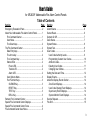
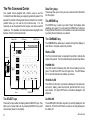
Fire Command Center XR2400F Users Guide 1 Silencing an Alarm While the fire alarm horns, strobes, or sirens are sounding use one of the following methods to silence the alarm. 1. Turn the keyswitch to enable the four function keys. Then press the SILENCE key. 2. Enter your user code. Then press COMMAND. Note: You may silence an alarm using both of the above methods on the Remote Fire Command Center as well. Copyright© 2000 Digital Monitoring Products, Inc. Information furnished by DMP is believed to be accurate and reliable. This information is subject to change without notice. 2 User's Guide for XR2400F Addressable Fire Alarm Control Panels Table of Contents Section Page Emergency Evacuation Plans .......................................... iv About Your Addressable Fire Alarm Control Panel ........... 1 Fire Command Center ................................................. 1 User Menu ................................................................... 1 The Select keys ........................................................... 2 The Fire Command Center .............................................. 2 Data Entry keys ........................................................... 2 The Arrow key ............................................................. 2 The Command key ...................................................... 2 Status LEDs ................................................................ 2 Power LED .............................................................. 2 Trouble LED ............................................................ 2 Alarm LED .............................................................. 2 User Options Menu ..................................................... 3 Four Function Keys ..................................................... 3 SILENCE Key.......................................................... 3 RESET Key ............................................................. 3 TEST Key ................................................................ 3 DRILL Key ............................................................... 3 Remote Fire Command Center ........................................ 3 Special Fire Command Center Displays .......................... 4 Special Fire Command Center Tones .............................. 4 Fire Command Center User Menu ................................... 5 Section Page Alarm Silence .................................................................. 6 Sensor Reset ................................................................... 6 Outputs On Off ................................................................ 7 Zone Status ..................................................................... 7 System Status ................................................................. 8 System Test ..................................................................... 8 User Codes ..................................................................... 9 User Code Authority Levels ......................................... 9 Programming Custom User Codes .............................. 10 Ambush Codes ............................................................ 11 Deleting User Codes ................................................... 11 Changing User COdes ................................................ 11 Setting the Date and Time ............................................... 12 Display Events ................................................................. 13 About the Display Events Seciton .................................... 14 Zone Event Displays ................................................... 14 User Code Change Event Displays ............................. 14 Supervisory Event Displays ......................................... 14 System Monitor Event Displays ................................... 14 Service Request .............................................................. 15 Fire Drill ........................................................................... 15 3 Emergency Evacuation Plans First Floor The National Fire Protection Association recommends that you establish an emergency evacuation plan to safeguard lives in the event of a fire or other emergency. Use the following steps as a guide. Second Floor Fire Escape Draw a floorplan of your home or business On a clean sheet of paper, draw the walls, windows, doors, and stairs. Also draw any obstacles that a person may encounter while exiting the building such as large furniture or appliances. Window Ladder Develop escape routes Determine at least two routes the occupants in each room can take to safely escape. One route can be the most obvious such as the door. Another can be through a window that can be easily opened. If the window is high off the ground, an escape ladder should be provided. Building Front Building Back Draw arrows on the floorplan to show escape routes from each room. Decide where to meet Prearrange a meeting place outside and away from where emergency personnel are likely to be working. A neighbor's house or across the street in the front of the house are good locations. Always perform a head count to make sure all occupants safely exited. NEVER ENTER A BURNING BUILDING. If the head count shows one or more persons missing, give this information immediately to the authorities. Never enter a building to look for someone. Practice your escape plans Devising an escape plan is only the beginning, before the plan can be effective everyone should practice the escape routes from each room. 4 Early detection The best way to survive a fire or other emergency is to get out early. The installation of a fire alarm system, with smoke and carbon monoxide detectors in each room, can greatly decrease your risk of loss or injury. Introduction About Your Addressable Fire Alarm Control Panel The Addressable Fire Alarm Control Panel has been designed with your safety and comfort in mind. It uses the latest in computer based technology to create the most advanced and user-friendly fire, security, and access control system available. The Addressable Fire Alarm Control Panel combines ease of use with a simple to understand Fire Command Center display to offer the full range of features requested by today’s fire system owners. You can turn portions of your protection on or off at any time by pressing a few keys. You can add, delete, and change personal user codes at any time or check the status of protection devices in the system. An added feature of the Addressable Fire Alarm Control Panel is the membrane keyboard that has four additional function keys you may use to easily perform a variety of functions. For more information about these prompts, please refer to LT-0185, XR200/XR2400F Programming Guide. Fire Command Center The XR2400F comes with a built-in LCD display with a 20 key membrane keyboard called the Fire Command Center. The keyboard is mounted behind an opening in the door of the red enclosure. The keyboard can be used to perform a variety of functions as listed in this User’s Guide. Introduction A Remote Fire Command Center is also available to use with the XR2400F Addressable Fire Alarm Control Panel. The remote keyboard can be placed anywhere throughout the premises. Both keyboards have four additional function keys, which can be used for silencing the alarms, resetting the smoke detectors, testing the system, and performing fire drills. Both keyboards require the user to turn a keyswitch to enable the four function keys. User Menu The keyboards also give you access to the User Menu, which contains all of the functions necessary to fully operate your system. Note: Because the XR2400F is based upon the XR200 Command Processor, some prompts provided on the User Menu are not necessary for XR2400F operation. If the User Menu provides you with an option not discussed in this User Guide, please disregard it and move on to the next prompt by pressing the COMMAND key. The following menu items are not used with the XR2400F: • Door Access • • • • Armed Areas Bypass Zones Zone Monitor Schedules 5 The Fire Command Center Data Entry keys Your system comes equipped with a built-in, easy to use Fire Command Center that allows you to properly operate the system. The keyswitch to the left of the keyboard must be turned to the “enable” position before you can use the four functions keys. It is not necessary to use the keyswitch when using a user code to perform operations. The illustration and descriptions below highlight some features of the Fire Command Center: These keys allow you to enter your user code and other information into the system. Status LEDs LCD Display SELECT keys The ARROW key The ARROW key is used to go back through the displays while operating your system. You can press the ARROW key to back up through the list of functions in the User Menu or to make a correction by erasing the last character you entered. The COMMAND key The COMMAND key allows you to advance through the displays or User Menu or complete a data entry function. Status LEDs The Fire Command Center incorporates three LEDs to indicate the status of the system. The three indicator lights are described below. Keyswitch POWER LED This LED remains ON steady when both AC and battery input are good. The LED turns OFF when AC input is low. The LED flashes for 1/2 second intervals when battery input is low. TROUBLE LED Function Keys Data Entry Keys COMMAND Key ARROW Key This LED turns ON when any trouble is displayed in the status list, such as AC, battery, phone line, transmit, ground fault, NAC, or any zone trouble. This light is OFF when no trouble is displayed in the status list. The SELECT keys ALARM LED There are four keys under the display called the SELECT keys. They allow you to choose what to do by pressing the SELECT key under choices being shown in the display. The ALARM LED is ON when any alarm is currently displayed in the status list. This LED is OFF when no alarm is currently displayed in the status list. 6 Introduction User Options Menu Remote Fire Command Center Press and hold the ARROW and COMMAND keys for about two seconds. The display shows SET BRIGHTNESS. Use the left SELECT key to lower the display brightness. Use the right SELECT key to increase the display brightness. Press COMMAND. The XR2400F Addressable Fire Alarm Control Panel can be expanded by adding a Remote Fire Command Center. With the Remote Fire Command Center, user’s can access the User Menu and perform the same functions as the Fire Command Center in the panel. All of the keys, except the four function keys, can be used at any time without turning the keyswitch. At SET TONE, use the left SELECT key to lower the keyboard tone. Use the right SELECT key to raise the tone. Press COMMAND. At SET VOLUME LEVEL, use the left SELECT key to lower the keyboard volume. Use the right SELECT key to raise the volume. Press COMMAND. At MODEL NUMBER, the model number of the keyboard is displayed. Press the ARROW key to exit out of the User Options menu. Four Function Keys The Fire Command Center has been designed with four additional keys on the left side of the keypad. After turning the keyswitch, you can quickly perform vital functions using these four keys. The four function keys can only be used when the keyswitch has been turned to the enable position. These keys are the same as those on the Fire Command Center in the panel. Both keyboards also have the same displays and prompts. Follow the same instructions for using both keyboards. Below is an illustration of the Remote Fire Command Center showing the keyswitch lock that enables the four function keys. Status LEDs LCD Display SELECT keys SILENCE Key Pressing the SILENCE key will silence the alarm bells. RESET Key Keyswitch Pressing the RESET key will perform a sensor reset and silence the alarm bells. TEST Key Pressing the TEST key will perform a system test. DRILL Key Pressing the DRILL key will display a prompt “SURE? YES NO”. Press YES to begin the fire drill. Press NO to return to the status list. Introduction Function Keys Data Entry Keys COMMAND Key ARROW Key 7 Special Fire Command Center Displays As you use your system, you will occasionally see a display that asks you to enter a code or that describes a condition on the system. Below are some examples of the displays you will see: ALARM A 24 hour zone, such as a fire zone, has been tripped. Your system may sound bells and/or sirens. SYSTEM TROUBLE or SERVICE REQUIRED There is a problem with one or more of the components in your system. Contact our service department as soon as possible. SYSTEM BUSY The Addressable Fire Alarm Control Panel is performing another task of a higher priority. This usually only takes a few moments. Special Fire Command Center Tones TROUBLE There is a problem with a protection device or system component. This display is accompanied by a description of the problem. Your keyboard also contains a small speaker that allows it to alert you to events as they occur on your system. Below are brief descriptions of the different tones you'll hear from the keyboard: ENTER CODE The system requires you to enter your user code. User codes can be required for turning your system on, turning your system off, and many other functions. Fire Alarm tone: An intermittent sweeping siren that sounds until the fire alarm is silenced. As you enter your user code, the display shows an asterisk (*) in place of each digit pressed. This keeps others from seeing your user code on the display as it’s entered. TRY AGAIN or INVALID CODE The user code you have entered is not recognized by the system. Check the user code and try again. Key press tone: A short beep each time you press a key and it’s acknowledged by the system. Trouble tone: A steady tone indicating a trouble condition on your system. Press any key except TEST or DRILL to silence. This only silences the keypad and does not correct the condition that originally caused the trouble. INVALID LEVEL All user codes have authority levels that allow the user to only access certain functions. When a user attempts a function outside their authority, the INVALID LEVEL message displays. 8 Introduction Fire Command Center User Menu Many of the features of your system have been put into a User Menu that you can access from the Fire Command Center or the Remote Fire Command Center. The menu requires you to enter your user code and then only shows those functions to which you have access. Some features displayed on the User Menu are not necessary for the XR2400F Addressable Fire Alarm Control Panel . Please disregard these prompts and displays. You may skip any displays and prompts not discussed in this User Guide by pressing the COMMAND key. To access the User Menu: 1. Press the COMMAND key until MENU? NO YES displays. 2. Select YES. The display shows ENTER CODE: –. Enter your user code and press COMMAND. You can now scroll down through the list of system features available to your authority level. User Menu Options The list below shows the User Menu options in the order they will appear in the display. A description of the options follows in this guide. Menu Option Description ALARM SILENCE Silences an alarm bell or siren. SENSOR RESET Resets smoke detectors that have latched due to an alarm condition. Introduction OUTPUTS ON/OFF Allows you to turn on or off any of the outputs. ZONE STATUS Allows you to enter a zone number and see if that zone is either armed, bypassed, in alarm, open, or shorted. SYSTEM STATUS Displays the current condition of the system's AC power, backup battery, and panel tamper (optional). SYSTEM TEST Tests the system's siren, communication to the central station, and backup battery. USER CODES Allows you to add, delete, or change user codes and authority levels. TIME Allows you to change the Day, Date, or Time that is currently in the system. DISPLAY EVENTS Allows you to view or print the last 200 events that occurred on your system. SERVICE REQUEST Allows you to send a message to the central station requesting service on the alarm system. FIRE DRILL Allows you to test the system’s notification appliances, such as fire bells. The following pages detail each user menu item and provide instructions on when and how to use them properly. 9 User Menu Alarm Silence Sensor Reset User Code Level: 2 and above. User Code Level: All users. Function: Silences the alarm bell or siren during an alarm. Function: Resets smoke or other latching detectors. Also clears Fire/ Supervisory alarm and trouble displays. Alarm Silence allows you to turn off the alarm bell or siren connected to your system during an alarm. Using Alarm Silence does NOT stop an alarm report from being sent to the central station and does not reset any alarmed devices. Use the Sensor Reset function to reset devices such as smoke detectors that have latched in alarm. Note: You can also silence an alarm by entering your user code and pressing COMMAND while the bell or siren is still sounding. Silencing the Alarms 1. Access the User Menu. 2. ALARM SILENCE? displays. 3. Press any SELECT key. The system silences the bell or siren and exits the User Menu. Sensor Reset is used to reset smoke and other latching detectors after they have been tripped. Once these detectors have tripped, they must be reset before they can detect any additional alarm conditions. When Sensor Reset is selected, power to the detectors is temporarily removed by the system allowing them to reset. Make sure all smoke is cleared from around the area of the smoke detectors before performing a Sensor Reset to prevent the alarm from occurring again. Resetting the Sensors 1. Access the User Menu. 2. Press COMMAND until SENSOR RESET displays. Using the SILENCE function key 3. The display shows SENSORS OFF for five seconds followed by SENSORS ON. The SILENCE function key can only be used after the keyswitch has been turned to the “Enable” position. 4. The display automatically exits the User Menu. The SILENCE key silences the alarms: The SILENCE key does NOT stop the alarm report from being sent to the central station. 10 Using the RESET function key The RESET function key can be used after the keyswitch has been turned to the “Enable” position. The RESET key performs a sensor reset and silences the alarm bells. User Menu Outputs On Off Zone Status User Code Level: 5 and above. User Code Level: All users. Function: Allows you to turn the system relay outputs on and off. Function: Displays a list of bypassed or alarmed zones. Also allows you to check the status of individual zones. This function is used to individually turn your system’s relay outputs on and off. Your system may use these outputs to control such devices as smoke detectors, heat detectors, and other notification appliances. Turning the Outputs On and Off 1. Access the User Menu. Zone Status can be used to give you a list of zones by category or display the current status of an individual zone number. The three categories that apply to the XR2400F are Alarmed, Bypassed, and Number. Checking the Zone Status 2. Press COMMAND until OUTPUTS ON/OFF? displays. 1. Access the User Menu. 3. Press any SELECT key to display OUTPUT: - ON OFF. 2. Press COMMAND until ZONE STATUS? is displayed. 4. Enter the output number you want to turn on or off. The output number will appear in the display. 3. Press any SELECT key to display ARM BYPS ALR NBR. 5. With the output number displayed, press the SELECT key under ON or OFF. The output is then turned on or off, depending on your selection, and remains in that state until you change it. 4. Select ALR for a list of zones that have gone into alarm during the current or previous armed period. Under certain conditions, some outputs cannot be turned on. If you select a restricted output, the display shows CANNOT TURN ON. 6. At the ZONE NO: - prompt, enter the zone number you want to check and press COMMAND. The zone number and name is displayed followed by its status. For example, a zone status for zone one (1) might be OFFICE SMOKE - OKAY. The displays are -OKAY = the zone is in a normal condition -BYPAS = the zone is bypassed -BAD = the zone is in a bad condition 6. The system automatically removes the output number and a new output number can be entered. Refer back to step 4. Press the ARROW key to exit the User Menu. 4. Select BYPS for a list of zones that are currently bypassed. 5. Press NBR and ZONE NO: - will be displayed. 7. After displaying the zone status, ZONE: - returns for you to enter another zone number. User Menu 11 System Status System Test User Code Level: All users. User Code Level: 4 and above. Function: Displays the current condition of internal system hardware. Function: System Test is used to test the battery, alarm bell or siren, and communication to the central station. The System Test function begins automatically as soon as you select it. System Status displays the condition of the panel's AC power, battery power, and optional panel tamper. When System Status is selected, each monitor is displayed followed by OKAY or TRBL (Trouble) to indicate the current condition. Checking the System Status 1. Access the User Menu. 2. Press COMMAND until SYSTEM STATUS? displays. 3. Press any SELECT key. The display starts listing each system monitor and status. For example: AC POWER - OKAY Below are the System Monitor displays: Display What it monitors 1. Access the User Menu. 2. Press COMMAND until SYSTEM TEST? displays. 3. Press any SELECT key. The system test begins automatically and the display shows: 1) BELL SOUNDING during a two second bell test, then: 2) BATTERY - OKAY or BATTERY - TRBL to indicate the condition of the battery, then: * 3) TRANSMIT TEST and ATTEMPT NO : 1 during the transmit test, then: AC POWER = AC power 4) TRANSMIT OKAY or TRANSMIT FAILED to show the results of the transmit test, then: BATTERY = Battery power 5) TEST END to indicate the System Test is complete. TAMPER = Panel enclosure tamper 6) You can end the transmit test by pressing the ARROW key. These are followed by either OKAY or TRBL (trouble). If TRBL is displayed, call the service department for assistance. 4. The system then displays its firmware version (for example, VER_105_7/24/00), the panel model (MODEL XR2400F), then exits the User Menu. 12 Using the System Test Function * The transmit test does not operate on local systems. Using the TEST function key The TEST function key can only be used after the keyswitch has been turned to the “Enable” position. User Menu User Code Authority Levels User Codes User Code Level: 9 only Function: Allows you to add, delete, and change a user's (person operating the system) user code or authority level. M e nu O ptions Sensor Reset There are three characteristics associated with each user code that define its capabilities within the system. Zone Status System Status Display Events Alarm Silence System Test Zone Monitor Outputs On/Off Service Request Fire Drill Set Time User Codes 125 User Number 34812 User Code 7 User Level User Number - Every user is numbered. This number identifies them to the system and can be transmitted to the central station User Code - Each user also has a 3 to 5 digit number they enter into the keyboard. NOTE: A User Code cannot begin or end with zero, or be in the range of 980 to 989, or be in the range of 1 to 299. User Names - Each code may also be programmed with the user’s name. Up to 16 characters may be entered. User Level - The user is also assigned a level of authority (1 to 9) or customized authority by the person administrating the system that determines the functions the user can access. 1 2 3 4 5 6 7 8 9 ✔ ✔ ✔ ✔ ✔ ✔ ✔ ✔ ✔ ✔ ✔ ✔ ✔ ✔ ✔ ✔ ✔ ✔ ✔ ✔ ✔ ✔ ✔ ✔ ✔ ✔ ✔ ✔ ✔ ✔ ✔ ✔ ✔ ✔ ✔ ✔ ✔ ✔ ✔ ✔ ✔ ✔ ✔ ✔ ✔ ✔ ✔ ✔ ✔ ✔ ✔ ✔ ✔ ✔ ✔ ✔ ✔ ✔ ✔ ✔ ✔ ✔ ✔ ✔ ✔ ✔ ✔ ✔ Note: Service Request is not displayed if it has not been enabled on your system. The following table lists system functions users are allowed to access based on the authority level assigned to their codes. User Menu 13 Programming Custom User Codes In addition to the preset authority levels, you can also create custom authority levels by selecting the CUSTOM option at the time the user is being added to the system. This option allows you to assign specific User Menu access to individual users. Adding User Codes 1. Access the User Menu. 2. Press COMMAND until USER CODES? displays. (NOTE: You must have a level 9 authority. If you enter the User Menu with a lower authority, the keyboard will not display USER CODES?.) 3. Press any SELECT key. ADD DEL CHG displays. 4. Press the SELECT key under ADD to add a new user code. 5. At the USER NUMBER:- prompt, enter a user number and press COMMAND. The display changes to CODE NO:- . 6. Enter a user code of 3 to 5 digits and press COMMAND. The user enters this number each time they make changes. If using access cards, present the card instead of entering a code. The code is displayed for four seconds. After the code is entered, the display changes to USER NUMBER ###. 7. A 16 character name may be entered to identify the user. Press any top row key to clear the current name. You may then enter the new name. After the name is entered, press COMMAND. 14 8. The display changes to LEVEL CUSTOM. Select LEVEL to assign a standard set of authorized functions as outlined in the User Code Authority Levels table on the previous page. 9. At the LEVEL: - display, enter an authority level from 1 to 9. Press COMMAND. The displays shows USER # ADDED. 10.Select CUSTOM to customize the functions you want the user to access. This allows users to have certain capabilities outside of a standard authority level. The following chart shows the custom menu with default selections. ALM SLNC (alarm silence) SNSR RST (sensor reset) OUTPUTS (outputs on/off) ZN STATS (zone status) SYS STAT (system status) SYS TEST (system test) NO NO NO NO NO NO USR CODE (user code) TIME (day, date, and time) DIS EVNT (display events) TEMP CODE (temporary code)* SERV REQ (service request) FIRE DRIL (fire drill) NO NO NO NO NO NO * YES allows you to then enter the number of days (1 to 250) that a temporary user code can operate. Default is 7 days. Temp users are deleted from the system at 12:00 AM on the last day. 11.Press the ARROW key to exit the User Menu. Note: It is recommended that user codes be enabled for only the function shown above. Other burglary functions are available to add to a user code, but are not relevant and, therefore, are not recommended. User Menu Ambush Codes Your system may be programmed to allow user number one (1) to be an Ambush code. This Ambush code functions identically to a standard code with the exception that it sends a silent alarm to the central station. This silent alarm alerts the operator to a duress situation at the premises and prompts the immediate notification of authorities. Deleting User Codes 1. Access the User Menu. 2. Press COMMAND until USER CODES? displays. 3. Press any SELECT key. ADD DEL CHG is displayed. 4. Press the SELECT key under DEL to delete a user code from the system. You must have a user code level of 9 or have a custom user code with that authority to be able to delete a user code. 5. At the USER NUMBER: - prompt, enter the user number you want to delete and press COMMAND. The displays changes to USER # DELETED. 6. The display then changes back to USER NUMBER: - allowing you to delete another user. Press the ARROW key twice to exit the User Menu. User Menu Changing User Codes 1. Access the User Menu. 2. Press the COMMAND key until USER CODES? displays. 3. Press any SELECT key. ADD DEL CHG is displayed. 4. Press the SELECT key under CHG to change a user code. 5. At the USER NUMBER: - prompt, enter the user number to change and press COMMAND. 6. The display changes to CODE NO: * * * * *. Press a SELECT key and enter the new user code. Press COMMAND. Note: Changing a user code does not change the user number. 7. The display then shows the current user name. Press any top row key to clear. To enter a Custom Name, press the number key above the letter that you wish to enter. Each number key displays three letters. Press the top row select key under the letter you wish to enter. Repeat until entire name is entered. 8. The display changes to LEVEL CUSTOM. Refer to Adding User Codes on the previous page for a description of this prompt. 9. After entering the authority level, the displays shows USER # CHANGED for five seconds followed by USER NUMBER: -. This display allows you to enter another user number to change. Press the ARROW key twice to exit the User Menu. 15 Setting the Date and Time User Code Level: 8 and above. Function: Allows you to change the current date and time displayed on the Addressable Fire Alarm Control Panel and used by the system to log events in its Event Memory program. Setting the System’s Date and Time 1. Access the User Menu. 2. Press COMMAND until TIME? key. displays. Press any SELECT 3. The display shows the current day and time. Press the COMMAND key. The current date is displayed. Press the COMMAND key to make any changes. 7. THU FRI SAT is displayed. Press the SELECT key under the correct day. You can use the ARROW key to toggle between the two day of the week displays. 8. Press the SELECT key under DATE to change the date. The displays shows MONTH:- Enter one or two digits for the month. Press COMMAND. DAY:Enter up to two digits for the day. Press COMMAND. YEAR:Enter up to two digits for the year. Press COMMAND. The display returns to the TIME DAY DATE display. Press the ARROW key to exit the User Menu. 4. TIME DAY DATE is displayed. 5. Press the SELECT key under TIME to change the time. The displays shows – : AM PM. Enter the current time and select AM or PM. The display changes back to TIME DAY DATE. 6. Press the SELECT key under DAY to change the day of week. SUN MON TUE WED is displayed. If the current day of the week is not displayed, press the COMMAND key. 16 User Menu Display Events User Code Level: All Users. Function: Allows you to review up to 200 past system events. There are three applicable event types: Zone Activity - Zone alarms, troubles, and restorals. User Code Changes - Adding, deleting, and changing user codes. Supervisory - Problems with the system’s hardware components. The system’s memory can hold a maximum of 200 events for 45 days. Any event older than 45 days is cleared automatically by the system. Also, once the full 200 events are stored, any new event causes the oldest event to be cleared. Using the Display Events 1. Access the User Menu. 2. Press the COMMAND key until DISPLAY EVENTS? displays. Press any SELECT key. 3. The display shows FRST LST PRT SRT. Select FRST (first) to view the oldest to newest events. Select LST (last) to view the newest to oldest events. If you select FIRST, use the COMMAND key to scroll up through the events. If you select LAST, use the ARROW key to scroll down through the events. Select SRT (sort) to sort through the Display Events log and collect information specific to a user or system event. 4. To use the Sort feature, press the SELECT key under SRT. FRST DATE: 8/21 is displayed. Press any SELECT key and enter a 4-digit beginning date for the sort. Press COMMAND. 5. LAST DATE: 10/17 is displayed. Press any SELECT key and enter a 4-digit ending date for the sort. Press COMMAND. 6. USER NUMBER: - is displayed. To sort events for a particular user, enter the user number or press COMMAND to sort for all users. To search for a user, press any SELECT key then use the COMMAND and ARROW keys to browse through the user names in the system. When the user you want is displayed, press any SELECT key then press COMMAND. 7. Next, the display shows five event types that you can include in the sort. Press the right SELECT key to display YES as the event type name is displayed. Press COMMAND. The following are the five sort event types: ACCESSES = door accesses granted (Not Applicable). DOOR NUMBER = leave blank for all doors (Not Applicable). ZONE EVENTS = zone alarms, troubles, and restorals. USER EVENTS = adding, deleting, and changing user codes. SUPERVISORY = system hardware problems. 8. After the last event type is displayed, again the display shows FRST LST PRT SRT. At this point, you can view or print the new sorted Display Events or press SRT for a new sort. Select PRT (print) to print the complete Display Events log. User Menu 17 About the Display Events Section User Code Change Event Displays This section of the user’s guide shows the User's Guide Display Events items for the Fire Command Center and Remote Fire Command Center displays. While in the Display Events function, use the COMMAND and ARROW keys to go forward or backward through the list of events. This displays any addition, deletion, or change to a user code. Display Description A DD 11: 41A 10 / 17 US:19 BY US:12 Zone Event Displays This section displays alarms, troubles, and other events that could occur on your protection zones. Some of the Zone and Event types listed here are not applicable to the XR2400F. Please disregard any displays that are not discussed in this User’s Guide. Display Description A LR 10: 23P 10/17 OFFICE SMOKE An alarm occurred at 10:23 PM on Oct. 17. Press any SELECT key to see the zone number and zone type. PANC - Panic EMRG - Emergency SUPV - Supervisory AUX1 - Auxiliary 1 AUX2 - Auxiliary 2 BURG - Burglary Supervisory Event Displays Display Description MSG 11: 58P 10 / 17 AUTO R ECALL The test report was sent to the central station at the date and time shown. System Monitor Event Displays This displays any problems with the system's AC power, battery, or phone line(s) or any opening of a tampered panel box. Display Event Types - There are 7 event types you may see here: ALR - Alarm TBL - Trouble LOW - Low battery MIS - Missing wireless transmitter FLT - Zone Fault SVC - Service smoke detector 18 User Code Event Types - There are 3 event types you may see here: ADD - User added DEL - User deleted CHG - User code or authority level has been changed. This displays the date and time of an automatic test report. Zone Type - There are 7 possible zone types you may see here. FIRE - Fire User 19 added by user 12 at 11:41 AM. Press the Select key under either user (US:) number for the user name. RST - Restore TBL 11:41A POW ER Description 10/17 An AC failure occurred on Oct. 17. Press the SELECT key under 10/17 for the time the failure occurred. User Menu System Monitor Event Types - There are 2 event types: Fire Drill TBL - Trouble RST - Restore System Monitor Event Names - There are 5 system monitors: User Code Level: 8 and above. POWER - AC power to panel BATTERY - On panel LINE 1 - Phone line number 1 LINE 2 - Phone line number 2 TAMPER - On panel box Your system may be programmed to allow a Fire Drill. The Fire Drill is used to test the fire bells, horns, and other notification appliances in your system. The Fire Drill turns on your system bell circuit, but does not send a message to the central station. Starting a Fire Drill 1. Access the User Menu. Service Request User Code Level: 8 and above. 2. Press COMMAND until the FIRE DRILL? displays. Press any SELECT key. 3. SURE? YES NO is displayed. Function: Allows you to send a Request for Service message to the central station when there is a problem on your system. 4. Press the SELECT key under YES to start the Fire Drill test. Ending a Fire Drill After the Display Events function and if this feature is programmed for your user code, you will see SERVICE REQUEST? displayed in the User Menu. If you would like to send a Request for Service report to the central station, press any top row SELECT key while SERVICE REQUEST? is displayed. After the Request for Service report is sent, REQUEST MADE is displayed for four seconds. Note: This function is only displayed if it is enabled on your system and the user code has authority. 1. Enter your code and press COMMAND to end the Fire Drill. 2. The Fire Drill test will automatically end with an ALARM SILENCE or the programmed Bell Cutoff time. Using the DRILL function key The DRILL function key can be used after the keyswitch has been turned to the “Enable” position. Press the DRILL function key. The display will show SURE? YES NO. Press YES to begin the fire drill. The fire drill will automatically end after the programmed Bell Cutoff time. User Menu 19 LT-0560 (8/00)