1
Silencing an Alarm
While the fire alarm horns, strobes, or sirens are sounding
use one of the following methods to silence the alarm.
1. Turn the keyswitch to enable the four
function keys.
Then press the SILENCE key.
OR
2. Enter your user code. Then press COMMAND.
Note: You may silence an alarm using both of the above
methods on the Remote Fire Command Center as well.
Copyright© 2009 Digital Monitoring Products, Inc.
Information furnished by DMP is believed to be accurate and reliable.
This information is subject to change without notice.
XR100FC/XR500FC User’s Guide
Table of Contents
Section
Page
Silencing an Alarm...................................................... b
Security Command User’s Guide................................. i
for XR100FC/XR500FC Panels.................................... i
Table of Contents........................................................ i
Emergency Evacuation Plans.................................... iii
Draw a floorplan of your home or business........................iii
Develop escape routes......................................................iii
Decide where to meet......................................................iii
Practice your escape plans................................................iii
Early detection.................................................................iii
Introduction............................................................... 1
About Your Addressable Fire Alarm Control Panel................ 1
Fire Command Center . .................................................... 1
User Menu....................................................................... 1
The Fire Command Center ............................................... 2
Using the Keypad............................................................. 3
Four Function Keys........................................................... 4
Special Fire Command Center Displays............................... 5
Special Fire Command Center Tones.................................. 6
Fire Command Center User Menu...................................... 7
Section
Page
Alarm Silence................................................................... 8
Sensor Reset.................................................................... 8
Outputs On Off............................................................... 9
Zone Status................................................................... 10
System Status................................................................ 11
System Test................................................................... 11
User Profiles.................................................................. 12
User Profiles Reference................................................... 13
User Codes.................................................................... 14
Setting the Date and Time.............................................. 16
Ambush Codes............................................................... 17
Display Events............................................................... 17
Service Request............................................................. 17
Fire Drill........................................................................ 17
Appendix A............................................................... 18
About the Display Events Section.................................... 18
Zone Event Displays....................................................... 19
User Code Change Event Displays................................... 19
Supervisory Event Displays............................................. 20
System Monitor Event Displays........................................ 20
XR100FC/XR500FC User’s Guide
i
Appendix B............................................................... 21
Zone Status Browser...................................................... 21
Outputs On/Off Browser................................................. 22
Output Groups Browser.................................................. 22
Change User Profiles Browser.......................................... 23
Add User Codes Browser................................................. 23
Delete User Codes Browser............................................. 24
Change User Codes Browser........................................... 24
Entering User Names...................................................... 25
Appendix C............................................................... 26
Common Keypad Displays............................................... 26
ii
XR100FC/XR500FC User’s Guide
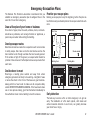
Emergency Evacuation Plans
The National Fire Protection Association recommends that you
establish an emergency evacuation plan to safeguard lives in the
event of a fire or other emergency.
Draw a floorplan of your home or business
On a sheet of paper, draw the walls, windows, doors, and stairs.
Also draw any obstacles, such as large furniture or appliances, a
person may encounter while exiting the building.
Practice your escape plans
Devising an escape plan is only the beginning, before the plan can
be effective everyone should practice the escape routes from each
room.
First Floor
Second Floor
Fire Escape
Develop escape routes
Determine at least two routes the occupants in each room can take
to safely escape. One route can be the most obvious such as the
door. Another can be through a window that can be easily opened.
If the window is high off the ground, an escape ladder should be
provided. Draw arrows on the floorplan to show escape routes from
each room.
Window Ladder
Building Front
Building Back
Decide where to meet
Prearrange a meeting place outside and away from where
emergency personnel are likely to be working. A neighbor’s house
or across the street in the front of the house are good locations.
Always perform a head count to make sure all occupants safely
exited. NEVER ENTER A BURNING BUILDING. If the head count shows
one or more persons missing, give this information immediately to
the authorities. Never enter a building to look for someone.
Early detection
The best way to survive a fire or other emergency is to get out
early. The installation of a fire alarm system, with smoke and
carbon monoxide detectors in each room, can greatly decrease
your risk of loss or injury.
XR100FC/XR500FC User’s Guide
iii
This page intentionally left blank
iv
XR100FC/XR500FC User’s Guide
Introduction
About Your Fire Alarm Control Panel
The Fire Alarm Control Panel is designed with your safety and
comfort in mind. It uses the latest in computer based technology
to create the most advanced and user-friendly fire, security, and
access control system available.
The Fire Alarm Control Panel combines ease-of-use with a simpleto-understand Fire Command Center display to offer the full range
of features requested by today’s fire system owners.
You can turn portions of your protection on or off at any time by
pressing a few keys. You can add, delete, and change personal user
codes at any time or check the status of protection devices in the
system. An added feature of the Fire Alarm Control Panel is the
membrane keyboard with four additional function keys you may use
to easily perform a variety of functions.
A Remote Fire Command Center is also available to use with the
XR100FC/XR500FC Addressable Fire Alarm Control Panel. The remote
keyboard can be placed anywhere throughout the premises.
Both keyboards have four additional function keys, to be used for
alarm silencing, resetting smoke detectors, system testing, and
performing fire drills. Both keyboards require the user to turn a
keyswitch to enable the four function keys.
User Menu
The keyboards also provide access to the User Menu, which contains
all of the functions necessary to fully operate your system.
Fire Command Center
The XR100FC/XR500FC comes with a built-in LCD display with a
20-key membrane keyboard called the Fire Command Center. The
keyboard is mounted behind an opening in the red enclosure door.
Use the keyboard to perform a variety of functions as listed in this
User’s Guide.
Introduction
XR100FC/XR500FC User’s Guide
1
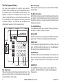
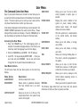
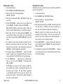
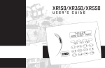
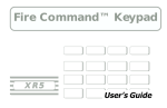
The Fire Command Center
Your system comes equipped with a built-in, easy-to-use Fire
Command Center that allows you to properly operate the system.
The Command Center is also available in a remote version. The
keyswitch to the left of the keyboard must be turned to the
“enable” position before you can use the four functions keys.
It is not necessary to use the keyswitch when using a user code
to perform operations. The illustration and descriptions below
highlight some features of the Fire Command Center:
Status LEDs
LCD Display
Select Keys
Fire Command Center
POWER
TROUBLE
Keyswitch
ALARM
SILENCE
RESET
ABC
TEST
MNO
DEF
1
GHI
2
JKL
3
4
ENABLE
DRILL
PQR
STU
5
6
9
0
YX
Function Keys
VWX
7
8
COMMAND
Back Arrow Key
Data Entry Keys
COMMAND Key
The Select keys
There are four keys under the display called the Select keys. They
allow you to choose what to do by pressing the Select key under
choices being shown in the display.
2
Data Entry keys
These keys allow you to enter your user code and other information
into the system.
The Back Arrow key
Use the Back Arrow key to go back through displays while operating
your system. Press the Back Arrow key to back up through the list
of User Menu functions or to make a correction by erasing the last
character you entered.
The Command key
The COMMAND key allows you to advance through the displays or
User Menu or complete a data entry function.
Status LEDs
The Fire Command Center incorporates three LEDs to indicate the
system status. The three indicator lights are described below.
Power LED
This LED remains ON steady when both AC and battery input are
good. The LED turns OFF when AC input is low. The LED flashes at
half-second intervals when battery input is low.
Trouble LED
This LED turns ON when any trouble displays in the status list, such
as AC, battery, phone line, transmit, ground fault, NAC, or any zone
trouble. This light is OFF when no trouble displays in the status
list.
Alarm LED
The ALARM LED is ON when any alarm currently displays in the
status list. This LED is OFF when no alarm currently displays in
the status list.
XR100FC/XR500FC User’s Guide
Introduction
Using the Keypad
Multi-lingual Display Option
Your system may be programmed to display the User Menu and
Status Display text in multiple languages. When the COMMAND
key is pressed, the option to choose the language displays. The
language chosen continues to display at this keypad until another
language is chosen.
Keypad Displays Current Programming
Most User Menu options displayed at the keypad show the currently
selected option in the panel memory. These options are either
shown as a number, a blank, or a NO or YES. To change a number
press any top row Select key. The current option is replaced with a
dash. Press the number(s) on the keypad you want to enter as the
new number for that option.
It is not necessary to enter numbers with leading zeros. The panel
automatically right justifies when you press the COMMAND key.
To change an option that requires a NO or YES response, press the
top row Select key under the response not selected.
For example, if the current option is YES and you want to change it
to NO, press the third top row Select key. The display changes to
NO. Press the COMMAND key to go to the next option.
Multiple Displays
For many User Menu options on burglary keypads of combination
burglary and fire systems, such as Access Areas, there are several
displays containing lists. For example, in Access Areas, areas 1
through 32 display on four separate displays. First, areas 1 through
8 display. Press the COMMAND key to display areas 9 through 16.
Press the COMMAND key again to display areas 17 through 25. Press
the COMMAND key one more time to display areas 26 through 32.
Asterisks in Burglary Area Armed Displays
Asterisks display next to a programming option that is already
selected. As shown in the example, options chosen to display
the current programming selection have an asterisk next to the
number. Those that are not selected simply display the number.
In the example, Burglary Areas 3, 8, 9, 15, 19, 23, 25, and 31 are
not selected. In both examples the numbers with asterisks are
selected.
Burglary Areas
*1
*2
3
*4
*17 *18
19
*20
*5
*6
*7
8
*21 *22
23
*24
9
*10
*11
*12
25 *26
15 *16
*29 *30
*13 *14
*27 *28
31
*32
To select or deselect a number, simply enter the number using the
digit keys on the keypad. This same scheme is used when viewing
the panel armed status and other programming and operational
functions. Remember to press the COMMAND key to display the
rest of the device or area numbers.
Note: Only areas pre-programmed at installation can display.
Introduction
XR100FC/XR500FC User’s Guide
3
User Options
Four Function Keys
The User Options allow you to make adjustments to your keypad to
best fit your environment and needs.
To access the User Options portion of the keypad, press and hold
the Back Arrow and COMMAND keys for two seconds. The keypad
display changes to SET BRIGHTNESS. Press the COMMAND key to
display the next option or the Back Arrow key to exit.
Backlighting Brightness
Sets the keypad LCD, and AC LED backlighting brightness level.
At the SET BRIGHTNESS display, use the left Select key to lower
the keypad brightness. Use the right Select key to increase the
brightness.
Note: If the brightness level is lowered, it temporarily reverts back
to maximum intensity whenever a key is pressed.
The Fire Command Center is designed with four additional keys on
the left side of the keypad. After turning the keyswitch, you can
quickly perform vital functions using these four keys.
SILENCE Key
Pressing the SILENCE key silences the alarm bells.
RESET Key
Pressing the RESET key performs a sensor reset and silence the
alarm bells.
TEST Key
Pressing the TEST key performs a system test.
DRILL Key
Pressing the DRILL key displays a prompt “SURE? YES NO”. Press
YES to begin the fire drill. Press NO to return to the status list.
Internal Speaker Tone
Sets the keypad internal speaker tone. At the SET TONE display,
use the top left Select key to make the tone lower. Use the right
Select key to make the tone higher.
Volume level
Sets the keypad internal speaker volume level for key presses and
prewarn conditions. During alarm, trouble, and prewarn conditions,
the volume is always at maximum level. At SET VOLUME LEVEL,
use the left Select key to lower the keypad volume. Use the right
Select key to raise the volume.
Model Number
The keypad model number, firmware version, and date display, but
cannot be changed.
4
XR100FC/XR500FC User’s Guide
Introduction
Special Fire Command Center Displays
As you use your system, you occasionally see a display that asks you
to enter a code or that describes a condition on the system. Below
are some examples of the displays:
ENTER CODE
The system requires you to enter your user code. User codes can
be required for turning your system on (arming), turning your
system off (disarming), and many other functions.
ALARM
A 24-hour zone (for example fire or panic) or an armed burglary
zone has been tripped. Your system may sound bells or sirens.
As you enter your user code, the keypad display shows an asterisk
(*) in place of each digit pressed. This keeps others from seeing
your user code on the display as it is entered.
ALARM NOT SENT (Burglary Keypad)
The alarm signal was not sent to the central station because a user
code was entered to disarm the system before the alarm signal was
sent to the central station.
TRY AGAIN or INVALID CODE
The user code you have entered is not recognized by the system.
Check the user code and try again.
ALARM CANCELLED (Burglary Keypad)
An Alarm Cancel signal was sent to the central station because
a user code was entered after an alarm was sent to the central
station.
SILENCED
An Alarm Silence has been performed to turn off the notification
appliances. Zone names are displayed on the bottom line of the
keypad display.
SUPVSRY (SUPERVISORY)
A Supervisory type zone alarm has occurred. The zone name is
displayed on the bottom line of the keypad display.
TROUBLE
There is a problem with a protection device or system component.
This display is accompanied by a description of the problem.
Introduction
INVALID PROFILE
All user codes have a profile that allow the user to only access
certain functions. When users attempt functions outside their
authority, the INVALID PROFILE message displays.
INVALID AREA
A user has attempted a door access for an area they are not
assigned.
INVALID TIME
A user code assigned to a specific schedule is entered outside of
the valid schedule. See Schedules and User Codes.
ARMED AREA
A user has attempted a door access to an armed area to which they
do not have arming and disarming authority.
XR100FC/XR500FC User’s Guide
5
FAILED TO EXIT (ANTI-PASS BACK) (Burglary Keypad)
Anti-passback requires users to properly exit (egress) an area they
have previously accessed. If they fail to exit through the proper
card reader location they are not granted access on their next
attempt. A Failed to Exit message appears when a user assigned
the anti-passback option attempts to re-enter an area which they
did not exit properly. The user must exit the area through the
proper door. If not possible, your system administrator should
select the Forgive option in the User Codes menu option.
SYSTEM TROUBLE or SERVICE REQUIRED
There is a problem with one or more of the components in your
system. Contact our service department as soon as possible.
SYSTEM BUSY
The Security Command system is performing another task of a
higher priority. This usually only takes a few moments.
Special Fire Command Center Tones
Your keypad also contains a small speaker that alerts you about
events as they occur on your system. For an alarm, as soon as
the first digit key is pressed to enter a user code, the tone stops.
If no other keys are pressed for five seconds or an invalid code is
entered, the tone turns on again.
Fire Alarm tone: An intermittent sweeping siren that sounds until
the fire alarm is silenced.
Key press tone: A short beep each time you press a key on the
keypad and it is acknowledged by the system.
Prewarn tone: A continuous pulsed tone that sounds when you
open an entry delay door on a system that is armed (turned on)
reminding you to disarm the protection. The tone silences as soon
as the first user code digit key is pressed.
Exit tone: A continuous pulsing tone that sounds during the exit
countdown just after arming to remind you to exit the premise. At
ten seconds prior to the end of the countdown, the rate of pulsing
increases.
Trouble tone: A steady tone indicating a trouble condition on your
system. Press a Select key to silence.
What to do when the trouble tone sounds
You can silence the trouble tone by pressing any key.
This only silences the keypad and does not correct the
condition that originally caused the trouble.
6
XR100FC/XR500FC User’s Guide
Introduction
Fire Command Center User Menu
User Menu
ZONE STATUS
Many of your system features are included in a User Menu you can
access from the Fire Command Center or the Remote Fire Command
Center. The menu requires you to enter your user code and then
only shows those functions to which you have access.
Some features displayed on the User Menu are not necessary for the
XR100FC/XR500FC Addressable Fire Alarm Control Panel. Please
disregard these prompts and displays. Press the COMMAND key to
skip any displays and prompts not discussed in this User Guide.
Accessing the User Menu
1. Press the COMMAND key, if the multi-language option is
enabled, the available languages display. Press the top row
Select key under the language to use for text display.
2. Press the COMMAND key until MENU? NO YES displays.
3. Select YES. The keypad displays ENTER CODE: –. Enter your
user code and press COMMAND. You can now scroll down
through the list of system features available to you.
User Menu Options
The list below shows the User Menu options in the order they
display.
Menu Option
ALARM SILENCE
SENSOR RESET
OUTPUTS ON/OFF
System Setup
Description
Silences an alarm bell or siren.
Resets smoke or glassbreak detectors
that have latched due to an alarm
condition.
Allows you to turn on or off any of the
outputs described in the System Setup
section of this guide.
SYSTEM STATUS
SYSTEM TEST
USER PROFILES
USER CODES
TIME
DISPLAY EVENTS
SERVICE REQUEST
FIRE DRILL
Allows you to see if a zone is either
armed, bypassed, in alarm, open, or
shorted.
Displays the current condition of the
system AC power, backup battery,
optional panel tamper, and keypad
model and version numbers.
Tests the system siren, communication
to the central station, and backup
battery.
Allows you to add, delete, or change
user profiles.
Allows you to add, delete, or change
user codes.
Allows you to change the Day, Date, or
Time that is currently programmed in
the system.
Allows you to view or print the last
10,000 door accesses or 2,000 system
events that occurred on your system.
Allows you to send a message to the
Central Station requesting service on
the alarm system.
Allows you to test the system fire bells.
The following pages detail each user menu item and provide
instructions on when and how to properly use them.
XR100FC/XR500FC User’s Guide
7
Alarm Silence
Sensor Reset
Silences the alarm bells or sirens during an alarm.
Resets smoke or glassbreak detectors. Also clears Fire/Supervisory
alarm and trouble displays.
Alarm Silence allows you to turn off the alarm bells and sirens
connected to your system during an alarm. Using Alarm Silence
does NOT stop an alarm report from being sent to the central
station and does not reset any alarmed devices. Use the Sensor
Reset function to reset devices such as smoke detectors that
latched in alarm.
Note: The keypad tone silences as soon as the first user code digit
key is pressed. You can also silence an alarm by entering your user
code and pressing COMMAND or by presenting your card to a reader
while the Status List displays. If using a proximity card, areas
assigned to your card may be disarmed and door access occurs.
Using the Alarm Silence Function
1. Access the User Menu.
Make sure all smoke is cleared from around the smoke detector
areas before performing a Sensor Reset to prevent the alarm from
occurring again.
Resetting the Sensors
1. Access the User Menu.
2. Press COMMAND until SENSOR RESET displays.
2. The keypad displays ALARM SILENCE?.
3. Press any Select key to silence the bells and exit the User
Menu.
8
Sensor Reset is used to reset smoke and glassbreak detectors after
they have tripped. Once these detectors trip, they must be reset
before they can detect any additional alarm conditions. When you
select Sensor Reset, power to the detectors is temporarily removed
by the system allowing them to reset.
3. The keypad displays SENSORS OFF for five seconds followed
by SENSORS ON.
4. The keypad automatically exits the User Menu.
XR100FC/XR500FC User’s Guide
System Setup
Outputs On Off
Allows you to manually turn the system or door access relay outputs
ON and OFF.
This function is used to individually turn your system relay and
access door outputs ON and OFF. Your system may use these
outputs to control door access, interior and exterior lighting,
heating, air conditioning, or other appliances.
The names and numbers of the relays connected to your system are
located in the System Setup section of this guide.
Turning the Outputs ON and OFF
1. Access the User Menu.
2. Press COMMAND until OUTPUTS ON/OFF? displays.
3. Press any Select key to display OUTPUTS DOOR.
4. Select the type of output you want to turn ON or OFF by
pressing the Select key under OUTPUTS or DOOR.
5. Enter the output number you want to turn ON or OFF. The
output number displays. The range for outputs is 1-6, 500999. The range for the door is 1-16.
Your system may be programmed to require that your user code
profile have access to areas assigned to the keypad. INVALID AREA
displays when your user code does not have access to the keypad’s
areas and the output does not turn on.
6. With the output number displays, press the Select key under
ON or OFF. The output then turns ON or OFF depending on
your Selection, and remains in that state until you change
it. The keypad displays the output or door name first 12
characters followed by either ON or OFF for four seconds to
provide visual verification of the action. Press the COMMAND
key to end the four second display.
Under certain conditions, some outputs cannot be turned
on. If you select a restricted output, the keypad displays
CANNOT TURN ON.
7. The system automatically returns to the output or door
prompt to allow you to select a new output to turn ON or
OFF. Refer back to step 4.
Outputs can be turned ON or OFF regardless of the output settings
in Schedules.
8. Press the Back Arrow key to exit the User Menu.
Browser Feature
If you are unsure of the output number, refer to
Appendix B at the back of this guide for a diagram showing you how
to use the built-in Outputs ON/OFF browser.
System Setup
XR100FC/XR500FC User’s Guide
9
Zone Status
Displays a list of armed, bypassed, or alarmed zones. Also allows
you to check individual zone status. Zone Status can be used to
give you a list of zones by category or display the current status of
an individual zone number. The four categories are:
4. At the ZONE NO: - prompt, enter the zone number you want
to check and press COMMAND. The zone number and name
display followed by the zone status. For example, a zone
status for zone 1 might be BACK DOOR - OKAY.
Below is a list of the zone status displays:
• Armed Zones - zones that are currently armed.
-OKAY = the zone is in a normal condition
• Bypassed Zones - zones that are currently bypassed.
-BYPAS = the zone is bypassed
• Alarmed Zones - zones that have gone into alarm during the
current or previous armed period.
-BAD
• Number - enter the number of any zone to check its status.
Using the Zone Status Function
1. Access the User Menu.
2. Press COMMAND until ZONE STATUS? displays.
3. Press any Select key to display ARM BYPS ALR NBR.
= the zone is in a bad or faulted condition
5. After displaying the zone status, ZONE: - returns for you to
enter another zone number.
Browser Feature
If you are unsure of the zone number or description, refer to
Appendix B at the back of this guide for a diagram showing you how
to use the built-in Zone Status browser.
3a. Select ARM for a list of zones that are currently armed.
You can scroll through the list by pressing the COMMAND
key.
3b. Select BYPS for a list of zones that are currently
bypassed.
3c. Select ALR for a list of zones that have gone into alarm
during the current or previous armed period.
3d. Press NBR and ZONE NO: - displays.
10
XR100FC/XR500FC User’s Guide
System Setup
System Status
System Test
Displays the internal system hardware current condition.
System Test is used to test the battery, alarm bell or siren, and
communication to a central station. The System Test function
begins automatically as soon as you select it.
System Status shows the panel condition of AC power, battery
power, and optional panel tamper. When System Status is selected,
each monitor displays followed by OKAY or TRBL (Trouble) to
indicate the current condition.
Using the System Test Function
1. Access the User Menu.
2. Press COMMAND until SYSTEM TEST? displays.
Using the System Status Function
1. Access the User Menu.
2. Press COMMAND until SYSTEM STATUS? displays.
3. The keypad displays SYSTEM PANICS. Press the Select key
below SYSTEM.
3. Press any Select key. The display starts listing each system
monitor and status.
4. The System Test begins automatically and the keypad displays
the following messages in this order:
1) BELL SOUNDING during a two second bell test
For example: AC POWER - OKAY
2) KEYPAD SOUNDING all keypads assigned to the same
area sound their alarm tone for two (2) seconds during
the keypad sounder test
Below are the System Monitor displays:
Keypad Display
AC POWER
What it monitors
AC power
BATTERY
Battery power
TAMPER
Panel box tamper
3) BATTERY - OKAY or BATTERY - TRBL to indicate the
battery condition
These are followed by either OKAY or TRBL (trouble).
If TRBL displays, call the service department for assistance.
4. The system then displays its firmware version (for example,
VER_201_3/08/04), the panel model (MODEL XR500N), and
then exits the User Menu.
4)* TRANSMIT TEST and ATTEMPT NO: 1 during the transmit
test
5) TRANSMIT OKAY or TRANSMIT FAILED to show the
results of the transmit test
6) TEST END to indicate the System Test is complete.
7) You can press the Back Arrow key to end the transmit
test.
System Setup
* The transmit test does not occur on local systems.
XR100FC/XR500FC User’s Guide
11
User Profiles
Using the Panic Zone Test
1. Access the User Menu.
2. Press COMMAND until SYSTEM TEST? displays.
3. Press any Select key. The keypad displays SYSTEM PANICS.
4. Press the Select key below PANICS.
5. The Panic Zone Test begins automatically and the keypad
displays TRIPS:
END.
During the Panic Zone Test, trip each panic zone (or button)
on the system by pressing and holding the panic for 1 to 2
seconds.
Note: You do NOT have to hold the panic for 2 seconds in normal
mode. You are only required to hold the panic during the
Panic Zone Test because the zone takes additional time to
report when the system is in test mode.
Each time you trip a panic zone, the display number
increments and the keypad buzzer sounds for two seconds.
The number of panic zones tripped constantly displays until
the test ends or no panic zone activity has occurred for 20
minutes.
6. Press the Select key below END to stop the Panic Zone Test.
7. PANIC TEST OKAY displays when the Panic Zone Test is
completed and all zones tested OK.
8. When the Panic Zone Test ends and a zone failed (did not
trip) during the test, the keypad displays the zone name and
number and the buzzer sounds for one second. Press the
COMMAND key to display the next failed zone.
Note: During the Panic Zone Test, any zones that fail are not sent to
the receiver unless pre-programmed at installation to be sent.
12
Change User Profiles, that define the authority of each user code
in the system. Several characteristics define the authority of each
User Profile within the system.
Profile Number - Each profile may be assigned a unique number
from 1 to 99.
Profile Name - Each profile may be assigned a 16-character name.
The Profile Number is the default name.
Arm or Disarm Areas - Each profile may be assigned specific areas
of the system for arming and disarming. When profiles 1 to 98 are
created, NO areas are assigned by default. The default for profile
99 is ALL areas assigned. Profile 99 is predefined in the system by
the factory.
Access Areas - Each profile may be assigned door access area
assignments. Default for profile 1 to 98 is NO areas assigned.
Default for profile 99 is ALL areas assigned. Profile 99 is predefined
at the factory.
Output Group Assignment - Each profile may be assigned an output
group number from 1 to 10. Default for profile 1 to 98 is NO output
group assigned. Default for profile 99 is output group 10. Your
system may by programmed to turn on an output group at certain
keypads when door access occurs.
User Menu Assignments - Each user profile may have any of the
menus assigned to it as shown in the User Profile Record below. The
User Profile Record lists the user menu profile assignments and the
system functions users are allowed to access based on the profile
numbers assigned to their codes.
Always make sure that at least one administrator in your system has
a profile with all authorities and all areas.
XR100FC/XR500FC User’s Guide
System Setup
User Profiles Reference
Menu Display
ARM
NO YES
DIS
NO YES
ALM SLNC
NO YES
SNSR RST
NO YES
DOOR ACS
NO YES
ARM AREA
NO YES
OUTPUTS
NO YES
ZN STATS
NO YES
BYPAS ZN
NO YES
ZONE MON
NO YES
SYS STAT
NO YES
SYS TEST
NO YES
PROFILES
NO YES
USR CODE
NO YES
SCHEDULS
NO YES
TIME
NO YES
DIS EVNT
NO YES
SERV REQ
NO YES
FIRE DRILL
NO YES
EXTEND
NO YES
TEMP CODE
NO YES
ANTI PASS
NO YES
ALOW: 1234
___ ANY
RE ARM DLY
0 – 250
SEC LANGUAGE
NO YES
System Setup
Privilege
Arm
Disarm
Alarm Silence
Sensor Reset
Door Access
Armed Areas
Outputs ON/OFF
Zone Status
Bypass Zones
Zone Monitor
System Status
System Test
User Profiles
User Codes
Schedules
Time
Display Events
Service Request
Fire Drill
Extend Schedules
Temporary User Code
Anti-Passback
Allow: Shift/Time Access
Re-Arm Delay
Preferred Language
Changing User Profiles
1. Access the User Menu.
2. Press COMMAND until USER PROFILES? displays.
3. Press any Select key. The keypad displays ADD DEL CHG.
4. Press the far right Select key, under CHG.
4. At the PROFILE NO: - option, enter a profile number and
press COMMAND. The display changes to PROFILE NAME.
5. Press any Select key to display -. Enter a profile name of up
to 16 characters. The default Profile Name uses the Profile
Number. Enter the name and press COMMAND.
6. At the Arm/Dis AREAS: option, enter the area numbers
(1-32) for arming and disarming assigned to this profile.
7. The keypad displays ACCESS Areas: . Enter the area numbers
(1-32) assignment to allow door access for this profile. Press
the COMMAND key.
8. The keypad displays OUTPUT GROUP: -. Enter the number
(1 through 20) for the Output Group assigned to this profile.
Press the COMMAND key.
9. The keypad displays each of the menus as shown in the
Profile Table. You then enable or disable the menu function
for this profile number. Select YES or NO and press the
COMMAND key to advance to the next menu selection.
10.When you complete Selecting all User Profile menu
assignments, the keypad displays the PROFILE CHNGD
message for 4 seconds, indicating the profile is changed.
TEMP CODE
When you select YES for this menu option, and this profile is
assigned to a user code (see next section), the keypad displays
TEMP EXPIRE DATE:. Enter the ending date for the profile to
expire. Default is seven days from today. The system deletes
Temp users at 12:00 AM on the last date.
XR100FC/XR500FC User’s Guide
13
ANTI PASS NO
Anti-passback requires that you properly exit (egress) an area
previously accessed. When you fail to exit through the proper
location you cannot access it until you properly exit. Default is
No. See page 6 for more information.
ALOW: 1 2 3 4 ANY
This menu option defines the time schedules that the User Code
operates for door access and disarming. Selecting 1, 2, 3, and/or
4 indicates operation during the S1-S4 shift schedules. Selecting
ANY (fourth Select key) from the menu indicates the code
operates any time, regardless of schedules. You may select all
shift schedules for one user. Menu access is not affected by this
option. An UNAUTHORIZED ENTRY message is sent to the central
station if disarming occurs outside the open/close schedule.
RE ARM DELAY
RE ARM DELAY allows the entry of 0 to 250 minutes to be used to
delay automatic rearming when the user disarms an area outside
of schedule. If zero is selected, the rearming occurs based on
permanent programming in the panel.
RE ARM DELAY is also used to delay a late to close message to the
central station when the panel does not use automatic arming.
If the user has Extend Schedule authority, 2HR 4HR 6HR 8HR
displays at disarming. If the user does not make a choice, the RE
ARM DELAY is used to extend the schedule.
Application example: An exit door near the trash is scheduled
to be armed at all times. When the custodian needs to remove
trash, program 10 minutes for the activity. Or, an overhead door
only requires access when a delivery is made. Program up to 250
minutes to allow the loading dock supervisor to load or unload a
semi-truck.
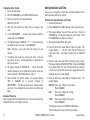
User Codes
This option allows you to add, delete, or change a user code. You
may also assign specific User Profiles to individual users.
3848
=
User Number
34812
=
User Code
John Smith
=
User Name
7
=
Profile
User Number - Every user is numbered 1 through 9999. This
number identifies the user to the system and is transmitted to the
central station when the user arms or disarms areas.
User Code - Each user also has a 3 to 6 digit code, to enter into the
LCD keypad when arming or disarming the system.
Note: A User Code cannot begin with zero and 3-digit codes cannot
begin with 98.
For UL installations, avoid using repetitive (111) or sequential
(123) codes.
User Names - Each code may also be programmed with the user
name. You may enter up to 16 characters for the name.
User Profile - The user is also assigned a Profile (1 to 99) by the
person administrating the system. The profile number determines
the areas and functions the user can access.
Note: Your system must have at least one user with user code
authority in order to be able to add or delete user codes. Be
careful not to delete all users with user code authority from your
system.
Browser Feature
Refer to Appendix B in this guide for a diagram showing you how to
use the Output Group browser and the Profile browsers.
14
XR100FC/XR500FC User’s Guide
System Setup
Adding User Codes
1. Access the User Menu.
2. Press COMMAND until USER CODES? displays.
3. Press any Select key. The keypad displays
ADD DEL CHG BAT.
4. Press the Select key under ADD or BAT (Batch) to add a new
user code.
5. At the USER NUMBER: - prompt, enter a user number and
press COMMAND. The display changes to USER CODE: - .
Note: Do NOT program a code for user number 1 unless you
intend to use the Ambush function, see Ambush on page 17.
6. Enter a user code of 3 to 6 digits and press COMMAND. The
user enters this number to arm, disarm, etc. After entering
the code the keypad displays USER NUMBER ### as the user
name.
7. A 16-character name may be entered to identify the user.
Press any top row key to clear the current name. You may
then enter the new name. After entering the name press
COMMAND. See Entering Names in Appendix B.
8. The display changes to PROFILE NO: -. Select the profile
number to assign a set of authorized functions to the user
code as outlined in the Profile Table on the previous page.
9. At the PROFILE NO:
- display, enter a profile number
from 1 to 99, and press COMMAND. The displays shows
USER # ADDED.
If BAT (Batch) was chosen in step 4 instead of ADD, the
next available user number is automatically selected and
only steps 6 and 7 repeat. The User Profile assignment
is automatically selected for the next user based on the
previous user entered. This batch entry method speeds up
user entry in large systems.
System Setup
Deleting User Codes
To delete a user code, you must have a user code with a profile that
has user code authority.
1. Access the User Menu.
2. Press COMMAND until USER CODES? displays.
3. Press any Select key. The keypad displays
ADD DEL CHG BAT.
4. Press the second Select key, under DEL, to delete a user code
from the system. To delete a user code, you must have a
user code with a profile that has user code authority.
Note: Be careful not to delete all users with user code
authority from your system. Also, the user code used to
enter the user menu to delete codes cannot be deleted. In
other words, you can not delete yourself.
5. At the USER NUMBER: - prompt, enter the user number you
want to delete and press COMMAND. The display changes to
USER # DELETED.
6. The display then changes back to USER NUMBER: - allowing
you to delete another user. Press the Back Arrow key twice
to exit the User Menu.
XR100FC/XR500FC User’s Guide
15
Setting the Date and Time
Changing User Codes
1. Access the User Menu.
2. Press the COMMAND key until USER CODES? displays.
Allows you to change the current date and time displayed on the
LCD keypad and used by the system.
3. Press any Select key. The keypad displays
ADD DEL CHG BAT.
Setting the System Date and Time
1. Access the User Menu.
4. Press the third Select key, under CHG, to change a user
code.
2. Press COMMAND until TIME? displays. Press any Select key.
5. At the USER NUMBER: - prompt, enter the user number to
change and press COMMAND.
3. The keypad displays the current day and time. Press the
COMMAND key. The keypad displays the current date. Press
the COMMAND key to make any changes.
6. The display changes to CODE NO: * * * * * *. Press a Select key
and enter the new user code. Press COMMAND.
4. The keypad displays TIME DAY DATE.
Note: Changing a user code does not change the user
number.
7. The display then shows the current user name. Press any
top row key to clear. See Entering Names in Appendix B to
enter a new name.
8. The display changes to PROFILE NO: -. Select the profile
number to assign a set of authorized functions to the user
code as outlined in the Profile Table on page 11.
9. After entering the profile number, the keypad displays
USER # CHANGED for 5 seconds followed by
USER NUMBER: -. This display allows you to change another
user code. Press the Back Arrow key twice to exit the User
Menu.
Browser Feature
Refer to Appendix B for diagrams showing you how to use the User
Codes Add, Delete, and Change browsers.
5. Press the Select key under TIME to change the time. The
keypad displays – : AM PM. Enter the current time and
select AM or PM. The display changes back to TIME DAY
DATE.
6. Press the Select key under DAY to change the day of week.
The keypad displays SUN MON TUE WED. Press the COMMAND
key to display THU FRI SAT. Press the Select key under the
correct day. Use the Back Arrow key to toggle between the
different day of the week displays.
7. Press the Select key under DATE to change the date. The
keypad displays
MONTH:- Enter up to 2 digits for the month.
Press COMMAND.
DAY:-
Enter up to 2 digits for the day.
Press COMMAND.
YEAR:- Enter up to 2 digits for the year.
Press COMMAND.
16
The display returns to the TIME DAY DATE display.
Press the Back Arrow key to exit the User Menu.
XR100FC/XR500FC User’s Guide
System Setup
Ambush Codes
Service Request
Your system may be programmed to allow user number 1 to be used
as an Ambush code. This Ambush code functions identically to a
standard code with the exception that it sends a silent alarm to the
central station. This silent alarm alerts the operator to a duress
situation at the premises and prompts immediate notification of
authorities.
Your user code profile may be programmed for Service Request.
This User Menu feature allows you to simply press any top row
Select key when SERVICE REQUEST? displays and have the system
automatically send a “Request for Service” message to the central
station. The display changes momentarily to REQUEST MADE to
confirm your request was sent.
Refer to the System Setup section of this guide to see if your system
is programmed for Ambush. If so, do NOT program a code for user
number 1 unless you intend to use the Ambush function.
Fire Drill
Display Events
Allows you to review up to 12,000 past door access and system
events. There are six event types:
Zone Activity - Zone alarms, troubles, and restorals.
User Code - Adding, deleting, and changing user codes.
Supervisory - Problems with system hardware components.
System Monitor- Problems with AC Power, Battery, phone line or
tamper problems.
The system memory holds a maximum of 12,000 past events for 45
days. Any event older than 45 days automatically clears from the
system memory. Also, once the full 12,000 events are stored, any
new event causes the oldest event to be cleared. See Appendix A
for Display Events.
System Setup
Fire Drill is used to test the fire bells or fire horns in your system.
The Fire Drill test turns your system bell circuit on, but does not
send a message to the central station.
Starting a Fire Drill test
1. Access the User Menu.
2. Press COMMAND until FIRE DRILL? displays. Press any Select
key.
3. The keypad displays SURE? YES NO.
4. Press the Select key under YES to start the Fire Drill test.
Ending a Fire Drill test
1. Enter your code at the keypad and press COMMAND to end
the Fire Drill.
2. The Fire Drill test automatically ends with ALARM SILENCE or
the programmed Bell Cutoff time.
XR100FC/XR500FC User’s Guide
17
Appendix A
About the Display Events Section
5. The keypad displays LAST DATE: 10/17. Press any Select
key and enter a 4-digit ending date for the sort. Press
COMMAND.
This section of the User’s Guide shows the Display Events items.
While in the Display Events function, use the COMMAND and Back
Arrow keys to go forward or backward through the list of events.
6. The keypad displays USER NUMBER: -. To sort events for a
particular user, enter their user number or press COMMAND
to sort for all users. To search for a user, press any Select
key then use the COMMAND and Back Arrow keys to browse
through the user names in the system. When the user you
want displays, press any Select key then press COMMAND.
The system memory holds a maximum of 12,000 past events for 45
days. Any event older than 45 days automatically clears from the
system memory. Also, once the full 12,000 events are stored, any
new event causes the oldest event to be cleared. See Appendix A
for Display Events.
7. The keypad next displays five event types that you can
include in the sort. Press the fourth Select key to display
YES as the event type name displays on the keypad. Press
COMMAND. The following are the five sort event types:
To view more information about each display, press the Select key
as directed in the explanations.
Using the Display Events
1. Access the User Menu.
2. Press the COMMAND key until DISPLAY EVENTS? displays.
Press any Select key.
3. The keypad displays FRST LST PRT SRT. Select FRST
(first) to view the oldest to newest events. Select LST (last)
to view the newest to oldest events. If you select FIRST, use
the COMMAND key to scroll up through the events. If you
select LAST, use the Back Arrow key to scroll down through
the events.
Select SRT to sort through the Display Events log and collect
information specific to a user or system event.
Select PRT to print the complete Display Events log.
4. To use the Sort feature, press the Select key under SRT.
The keypad displays FRST DATE: 8/21. Press any Select
key and enter a 4-digit beginning date for the sort. Press
COMMAND.
18
ACCESSES = door accesses granted.
DOOR NUMBER = leave blank for all doors.
Note: If you select yes for access then only Door Access
Granted Events are included in the sort.
ZONE EVENTS = zone alarms, troubles, and restorals.
USER EVENTS = adding, deleting, and changing user codes.
SUPERVISORY = system hardware problems and door access
denied events.
8. After the last event type displays, the keypad again displays
FRST LST PRT SRT. You can now view or print the sorted
Display Events or press SRT to define a new sort.
XR100FC/XR500FC User’s Guide
Appendix A
Zone Event Displays
User Code Change Event Displays
This displays alarms, troubles, and other events that may occur on
your protection zones.
This displays any addition, deletion, or change to a user code.
32-Character Display
ALR 10:23P 10/17
Basement door
Description
An alarm occurred at 10:23 PM
on Oct. 17. Press any Select
key to see the zone number
and zone type.
Zone Type - There are seven possible zone types you may see
here.
FIRE - Fire
PANC - Panic
BURG - Burglary
EMRG - Emergency
SUPV - Supervisory
AUX1 - Auxiliary 1
AUX2 - Auxiliary 2
Event Types - There are seven event type you may see here:
ALR - Alarm TBL - Trouble
RST - Restore
FLT - Zone Fault
SVC - Service smoke detector
LOW - Low battery
MIS - Missing wireless transmitter
Note: LOW and MIS are for wireless systems only.
Appendix A
32-Character Display
Add 11:41A 10/ 17
U:19byu:12
Description
User 19 added by user 12 at
11:41 AM. Press the Select key
under either user (US:) number
for the user name.
User Code Event Types - There are three event type you may see
here:
ADD - User added
DEL - User deleted
CHG - User code or authority level changed.
XR100FC/XR500FC User’s Guide
19
Supervisory Event Displays
System Monitor Event Displays
This displays the date and time of an automatic test report.
This displays any problems with the system AC power, battery, or
phone line(s), or any opening of a tampered panel box.
32-Character Display
Msg 11:58P 10/ 17
Auto recall
Description
The test report was sent to the
central station at the date and
time shown.
32-Character Display
tbl
11:41A 10/ 17
power
Description
An AC failure occurred at 11:41
AM. on Oct. 17.
System Monitor Event Types - There are 2 event types:
TBL - Trouble
RST - Restore
System Monitor Event Names - There are 5 system monitors:
POWER - AC power to panel
BATTERY - On panel
LINE 1 - Phone line number 1 LINE 2 - Phone line number 2
TAMPER - On panel box
20
XR100FC/XR500FC User’s Guide
Appendix A
Appendix B
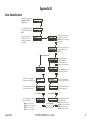
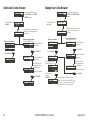
Zone Status Browser
Access the User Menu. Press
COMMAND until ZONE
STATUS appears.
ZONE STATUS?
Press any SELECT key then
press the SELECT key under
NBR.
ARM BYPS ALR NBR
Press one of the left two
SELECT keys to browse
through the programmed
zone names.
ZONE NO: -
SELECT AREA . . .
COMMAND
This prompt allows you to search
for a zone by area. Press the
COMMAND key to scroll through
the list of areas.
When the area where the zone is
located displays, press any
SELECT key.
FRONT OFFICE
COMMAND
24 HOUR ZONES
COMMAND
SELECT ZONE . . .
SELECT ZONE . . .
Press the COMMAND key to scroll
through the zone names list.
COMMAND
COMMAN
D
When the correct zone name
EAST DOOR
displays, press any SELECT key.
HALL SMOKE
When the correct zone name
displays, press any SELECT key.
Verify the zone number matches
the previously shown name.
ZONE NO : 0 3 4
Verify the zone number matches
the previously shown name.
ZONE NO : 0 1 2
Press COMMAND.
COMMAN
D
The system displays one of these EAST DOOR - OKAY
zone status messages:
-OKAY = the zone is normal
COMMAN
-BYPAS = the zone is bypassed
D
-BAD O = the zone is open
-BAD S = the zone is shorted
Appendix B
After all the areas display,
the system allows you to
search through the 24 hour
zones (Fire, Panic, Supervisory,
etc.).
Press COMMAND.
COMMAND
HALL SMOKE - OKAY
Pressing COMMAND
allows you to enter
another zone number.
XR100FC/XR500FC User’s Guide
COMMAND
The system displays one of these
zone status messages:
-OKAY = the zone is normal
-BYPAS = the zone is bypassed
-BAD O = the zone is open
-BAD S = the zone is shorted
21
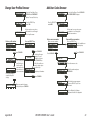
Outputs On/Off Browser
Output Groups Browser
OUTPUTS ON/OFF?
OUTPUTS
DOOR
Access the User Menu. Press
the COMMAND key until
OUTPUTS ON/OFF? displays.
Press the Select key under
OUTPUTS or DOOR.
OUTPUT: - ON OFF
DOOR: - ON OFF
Press either of the two left
SELECT keys.
SELECT OUTPUT . . .
SELECT DOOR . . .
This prompt allows you to
search for a door or an output.
Press the COMMAND key to
scroll through the list of doors
or output names.
OUTPUT GROUP: -
Access OUTPUT GROUP: in the USER PROFILES?
menu. Press any Select key.
SELECT GROUP . . .
At this prompt you can scroll
through the list of output group
names.
COMMAND
SELECT ZONE . . .
Press COMMAND.
The first output group name
displays.
COMMAND
OFFICE FRONT DR
OUTPUT: 127 ON OFF
DOOR: 128 ON OFF
22
When the door or output you
want displays, press any Select
key.
COMMAND
Press COMMAND.
SELECT ZONE . . .
The next output group name
displays.
FRONT OFFICE
Press any Select key and
the output group number
displays.
The display shows the door or
output number.
XR100FC/XR500FC User’s Guide
Appendix B
Change User Profiles Browser
USER PROFILES?
ADD DEL CHG
PROFILE NO:
-
Enter a profile number
.
2
3
At this prompt, you can enter a
profile number or scroll through
the list of profile names.
SHIPPING
SHIPPING
–
Follow the prompts to
complete the profile
change.
You can also press
any Select key to
clear the profile
name and use the
PROFILE NO: 012
data entry keys to
enter a new name.
COMMAND
Press any SELECT key.
The first available user
number displays.
USER NUMBER: 012
USER NUMBER: 12
1
Press COMMAND.
View available user numbers.
Enter a new user number.
4
COMMAND
At this prompt, you can enter a new
user number or scroll through the
available user numbers.
USER NUMBER:
-
Enter a new user number.
SELECT PROFILE . . .
COMMAND
Access the User Menu. Press COMMAND
until USER CODES? displays.
USER CODES?
Press the SELECT key ADD DEL CHG
under ADD.
Press the SELECT key
under CHG.
Press any SELECT key.
PROFILE NO: 12
1
Add User Codes Browser
Access the User Menu. Press
COMMAND until PROFILES?
displays. Press any Select key.
Press COMMAND.
The first profile name
displays. To scroll
through the list press
the COMMAND key.
If this is the profile you
want to change, press
any Select key.
2
3
Press COMMAND.
Verify the profile number.
4
COMMAN
D
COMMAND
Press COMMAND.
CODE NO: 1
2
3
4
CODE NO: 1 2 3 4
Press COMMAND.
Enter the new user code.
Verify the number and press
COMMAND.
COMMAN
D
COMMAND
PROFILE 12 CHNGD
Appendix B
USER 012
The default user name appears.
Press any SELECT key to clear
this name.
-
See the Entering User Names
diagram at the end of this Appendix
When you complete changes
to the profile, press COMMAND.
XR100FC/XR500FC User’s Guide
23
Delete User Codes Browser
USER CODES?
Change User Codes Browser
Access the User Menu. Press
the COMMAND key until USER
CODES? displays.
Press the SELECT key
under CHG.
Press the SELECT key ADD DEL CHG
under DEL.
USER NUMBER:
-
Enter a user number.
USER NUMBER: 12
1
2
3
At this prompt, you can enter a user
number or scroll through the list of
user names.
View current user names.
Press any SELECT key.
The first available user
MIKE JONES
name displays.
Enter a user number.
1
2
3
At this prompt, you can enter a user
number or scroll through the list of
user names
View current user names.
Press any SELECT key.
The first available user
MIKE JONES
name displays.
4
COMMAND
Press COMMAND.
Press COMMAND.
The next available user
name displays.
KATIE SMITH
USER NUMBER: 013
If this is the user you
want to delete, press
any SELECT key.
Verify the user number.
COMMAN
D
USER 13 DELETED
Press COMMAND.
Press COMMAND.
COMMAN
D
COMMAN
D
USER 12 DELETED
24
ADD DEL CHG
USER NUMBER:
-
USER NUMBER: 12
Access the User Menu. Press
COMMAND until USER CODES?
displays.
4
COMMAND
Press COMMAND.
USER CODES?
CODE NO: * * * * *
The next available user
name displays.
KATIE SMITH
Press any SELECT key to
clear the present code.
CODE NO:
USER NUMBER: 013
If this is the user you
want to change, press
any SELECT key.
Verify the user number.
1
2
3
Enter a new code
and press
COMMAND.
KATIE SMITH
XR100FC/XR500FC User’s Guide
4
COMMAN
D
COMMAN
D
Press COMMAND.
Follow the prompts to complete the code
change. You can also press any SELECT key
here to clear a custom user name and use the
data entry keys to enter a new user name.
Appendix B
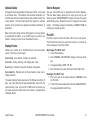
Entering User Names
-
1
To enter a custom name into
the keypad, you use the
three rows of number keys.
{
1
2
3
4
5
6
7
8
9
0
COMMAND
1
2
Once you've cleared the default
name, the display shows a dash
on the display left side.
3
A BC
Under each number key are
three letters.
To enter a custom name, press
the number key above the letter
you want to enter.
With the number displayed, press
the SELECT key that matches the
position of the letter. See example.
1
B
A
C
4
A
1
2
3
5
6
7
9
0
4
Once the letter you want displays,
press the number key above the
next letter you want to enter.
8
COMMAND
You can enter up to 16 characters
for each name into the keypad.
The nine and zero keys . . .
9
Y
0
Z (space)
Pressing the 9 key provides you
with Y, Z, and a space to use
between names. For example:
BOB SMITH.
Appendix B
–
.
*
#
Pressing the 0 (zero) key provides
you with a – (dash), . (period),
* (asterisk), and a # (pound sign).
XR100FC/XR500FC User’s Guide
25
Appendix C
Common Keypad Displays
Listed below are several keypad messages you may see on the display. Follow the instructions in the Possible Solutions column to
correct the problem. In many cases, you need to call a service person to correct the problem. Displays that are not discussed here
mean that your service representative should be called.
Message
Meaning
Invalid Area
The user has attempted a door access to an area they
are not assigned.
Change the user access areas if access to the area is
needed. If access is not needed, the user cannot enter
the area.
The user code you entered is not recognized by the
system.
Check the user code and try again.
A user has attempted a function that is outside of the
assigned profile.
Check the user profile settings.
A user code assigned to a specific schedule was
entered outside of the valid schedule.
See Schedules and User Codes.
Check the system clock.
The area you are attempting to disarm or access is a
Two Man Area.
A second and different user code must be entered.
Invalid Code
Invalid Profile
Invalid Time
Enter 2nd Code
26
Possible Solutions
Closing Time!
The scheduled has expired and in a short time the area Users still on the premise should arm the system or
will automatically arm.
extend the schedule to a later time.
Late to Close
The system was not armed at its scheduled closing
time.
Users still on the premise should arm the system or
extend the schedule to a later time.
Failed to Exit
A user assigned the anti-passback option has
attempted to re-enter an area from which they did not
exit properly.
The user must exit the area through the proper door. If
not possible, your system administrator should select the
Forgive option in the User Codes menu.
XR2500F User’s Guide
Appendix C
Index
A
Add User Codes 15
Browser 23
ALARM 5
Cancelled 5
Not Sent 5
ALARM LED 2
Alarm Silence 8
Ambush Codes 17
Anti-Pass Back 5, 14
Area Display 3
Armed Areas 5
Asterisks 3
B
Back Arrow key 2
Browser
Add User Codes 23
Change User Codes 24
Change User Profiles 23
Delete User Codes 24
Outputs On/Off 22
Output Groups 22
Zone Status 21
C
Change User Codes 16
Browser 24
Index
Change User Profiles 13
Browser 23
COMMAND key 2
D
Data Entry keys 2
Date and Time 16
Delete User Codes 15
Browser 24
Displays
ALARM 5
Alarm Cancelled 5
Alarm Not Sent 5
Area 3
Armed Area 5
Device 3
Enter Code 5
Invalid Area 5
Invalid Code 5
Invalid Profile 5
Invalid Time 5
Multi-lingual Option 3
Service Required 6
Silenced 5
Supervisory 5
System Busy 6
System Trouble 6
Trouble 5
XR100FC/XR500FC User’s Guide
Try Again 5
Display Events 17, 18
Supervisory Event Displays 20
System Monitor Event Displays 20
User Code Change Event Displays 19
Zone Event Displays 19
DRILL Key 4
E
Entering User Names 25
F
Failed to Exit 6
Fire Command Center 1, 2
ALARM 5
Back Arrow Key 2
COMMAND key 2
Data Entry Keys 2
Function keys 4
Select Keys 2
Status LEDs 2
Fire Command Center Displays 5
Fire Command Center Tones
Exit 6
Fire Alarm 6
Key Press 6
Prewarn 6
Trouble 6
27
Fire Drill 17
Function Keys 4
DRILL Key 4
RESET Key 4
SILENCE Key 4
TEST Key 4
I
Invalid Area 5
Invalid Profile 5
Invalid Time 5
K
Keypad Display Options 3
Asterisks 3
Current Programming 3
Multi-lingual 3
L
LEDs 2
Alarm LED 2
Power LED 2
Trouble LED 2
M
Multi-lingual Display 3
O
Outputs On/Off 9
Browser 22
Output Groups
28
Browser 22
P
Panic Zone Test 12
Profiles 12
Changing 13
Programming
Current Keypad Display Options 3
R
Re-Arm Delay 14
Remote Annunciator Keypad 5
Remote Fire Command Center 5
S
Select keys 2
Sensor Reset 8
Service Request 17
Service Required 6
Shfit Schedules 14
Silenced 5
Status LEDs 2
System Busy 6
System Status 11
System Test 11
System Trouble 6
Exit tone 6
Fire Alarm tone 6
Key press tone 6
Prewarn tone 6
Trouble tone 6
TROUBLE LED 2
U
User Codes 14
Adding 15
Changing 16
Deleting 15
Names 14
User Menu 1, 7
User Profiles 12
Anti-Pass Back 14
Re-Arm Delay 14
Shift Schedules 14
Temporary Code 13
Z
Zone Status 10
Browser 21
T
TEMP CODE 13
Tones 6
XR100FC/XR500FC User’s Guide
Index
This page intentionally left blank.
LT-1092 1.01 © 2009 Digital Monitoring Products, Inc.
9505