1
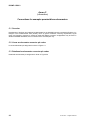
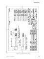
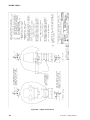
© ISO 2011 – All rights reserved
ISO TC 22/SC 12 N
Date: 2011-02-10
ISO/WD 15830-3
ISO TC 22/SC 12/WG 5
Secretariat: AFNOR
Road vehicles — Design and performance specifications for the
WorldSID 50th percentile male side impact dummy — Part 3: Electronic
subsystems
Véhicules routiers — Conception et spécifications de performance pour le mannequin mondial, 50 ème
percentile homme, de choc latéral — Partie 3: Sous-systèmes électroniques
Warning
This document is not an ISO International Standard. It is distributed for review and comment. It is subject to
change without notice and may not be referred to as an International Standard.
Recipients of this draft are invited to submit, with their comments, notification of any relevant patent rights of
which they are aware and to provide supporting documentation.
Document type: International Standard
Document subtype:
Document stage: (20) Preparatory
Document language: E
C:\worldsid\200901
ISO
15830\20110201
3_20110210_format_reviewed_lcr.doc STD Version 2.1c2
revisions\ISO_WD_15830-
ISO/WD 15830-3
Copyright notice
This ISO document is a working draft or committee draft and is copyright-protected by ISO. While the
reproduction of working drafts or committee drafts in any form for use by participants in the ISO standards
development process is permitted without prior permission from ISO, neither this document nor any extract
from it may be reproduced, stored or transmitted in any form for any other purpose without prior written
permission from ISO.
Requests for permission to reproduce this document for the purpose of selling it should be addressed as
shown below or to ISO's member body in the country of the requester:
ISO copyright office
Case postale 56 • CH-1211 Geneva 20
Tel. + 41 22 749 01 11
Fax + 41 22 749 09 47
E-mail [email protected]
Web www.iso.org
Reproduction for sales purposes may be subject to royalty payments or a licensing agreement.
Violators may be prosecuted.
ii
© ISO 2011 – All rights reserved
ISO/WD 15830-3
Contents
Page
Foreword .........................................................................................................................................................vi Introduction .................................................................................................................................................... vii 1
Scope ...................................................................................................................................................1 2
Normative references .........................................................................................................................1 3
Terms and definitions .........................................................................................................................1 4
4.1
4.1.1
4.1.2
4.1.3
4.2
4.2.1
4.2.2
4.2.3
Electrical subsystems requirements .................................................................................................2 Permissible sensors ...........................................................................................................................2 General ................................................................................................................................................2 Locations and specifications .............................................................................................................2 Sensor specifications and mass ........................................................................................................3 Permissible internal data acquisition system (DAS) ........................................................................7 General ................................................................................................................................................7 DAS characteristics ............................................................................................................................8 DAS mass and mass distribution ......................................................................................................8 5
5.1
Methods ...............................................................................................................................................8 Calculation of IR-TRACC distances from the IR-TRACC voltage outputs ......................................8 Annex A (normative) Load cell characteristics ............................................................................................10 A.1
Load cell capacities .......................................................................................................................... 10 A.2
Load cell sign conventions .............................................................................................................. 10 Annex B (informative) Conventions for exemplar permissible load cells and angular displacement
sensors .............................................................................................................................................. 15 B.1
Overview ............................................................................................................................................ 15 B.2
Repeatability and reproducibility ..................................................................................................... 15 B.3
Durability ........................................................................................................................................... 15 B.4
Sensitivity .......................................................................................................................................... 15 B.5
Handling ............................................................................................................................................ 15 B.6
Calibration ......................................................................................................................................... 17 B.7
Load cell connector pin codes.........................................................................................................17 B.8
Universal neck load cell (W50-71000) .............................................................................................. 19 B.9
Sacro-iliac load cell (W50-71130) ..................................................................................................... 19 B.10 Lumbar load cell (W50-71120) .......................................................................................................... 20 B.11 Pubic symphysis load cell (W50-71051) .......................................................................................... 20 B.12 Femoral neck load cell (W50-71080) ................................................................................................ 20 B.13 Universal leg load cell (W50-71010) ................................................................................................. 20 B.14 Shoulder load cell (W50-71090) ....................................................................................................... 20 B.15 Universal arm load cell (W50-71070) ............................................................................................... 20 B.16 Elbow load cell (W50-71060) ............................................................................................................ 21 B.17 Knee contact load cell (W50-71020) ................................................................................................ 21 Annex C (informative) Conventions for examplar permissible accelerometers ........................................22 C.1
Overview ............................................................................................................................................ 22 C.2
Linear accelerometer connector pin codes .................................................................................... 22 C.3
Rotational accelerometer connector pin codes..............................................................................22 Annex D (informative) Information regarding sensor output polarities .....................................................24 D.1
Overview ............................................................................................................................................ 24 D.2
Sensor output polarity diagrams ..................................................................................................... 24 © ISO 2011 – All rights reserved
iii
ISO/WD 15830-3
Figures
Figure A.1 — Universal neck load cell ............................................................................................................ 11 Figure A.2 — Sacro-iliac load cell ................................................................................................................... 11 Figure A.3 — Sacro-iliac load cell, right side, top, and left side views ............................................................. 11 Figure A.4 — Lumbar load cell........................................................................................................................ 12 Figure A.5 — Pubic symphysis load cell ......................................................................................................... 12 Figure A.6 — Femoral neck load cell .............................................................................................................. 12 Figure A.7 — Universal leg load cell ............................................................................................................... 13 Figure A.8 — Shoulder load cell ..................................................................................................................... 13 Figure A.9 — Universal arm load cell .............................................................................................................. 13 Figure A.10 — Elbow load cell ........................................................................................................................ 14 Figure A.11 — Knee contact load cell ............................................................................................................. 14 Figure B.1 — Humanetics (formally Robert A. Denton) WorldSID instrumentation ......................................... 16 Figure B.2 — Connector wiring, 31-pin, 6 channels ........................................................................................ 17 Figure B.3 — Connector wiring, 21-pin, 3 channels (shoulder) ....................................................................... 17 Figure B.4 — Connector wiring, 15-pin, 2 channels (elbow load cell) ............................................................. 18 Figure B.5 — Connector wiring, 15-pin, 1 channel (side exit, pubic) ............................................................... 18 Figure B.6 — 1-channel connector to G5 DAS (configuration shown was only used in some WorldSID
assemblies) ............................................................................................................................................. 18 Figure B.7 — 2-channel connector to G5 DAS (configuration shown was only used in some WorldSID
assemblies) ............................................................................................................................................. 19 Figure B.8 — 3-channel connector to G5 DAS (configuration shown was only used in some WorldSID
assemblies) ............................................................................................................................................. 19 Figure C.1 — Linear accelerometer wiring ...................................................................................................... 23 Figure D.1 — Head accelerometers ................................................................................................................ 25 Figure D.2 — Upper neck load cell ................................................................................................................. 26 Figure D.3 — Lower neck load cell ................................................................................................................. 27 Figure D.4 — Thorax accelerometers ............................................................................................................. 28 Figure D.5 — Rib displacement ...................................................................................................................... 29 Figure D.6 — Shoulder load cell ..................................................................................................................... 30 Figure D.7 — Arm accelerometers .................................................................................................................. 31 iv
© ISO 2011 – All rights reserved
ISO/WD 15830-3
Figure D.8 — Arm sensors ............................................................................................................................. 32 Figure D.9 — Pelvis accelerometers ............................................................................................................... 33 Figure D.10 — Lumbar spine load cell ............................................................................................................ 34 Figure D.11 — Sacro-iliac load cell ................................................................................................................. 35 Figure D.12 — Pubic load cell ........................................................................................................................ 36 Figure D.13 — Femoral neck load cells .......................................................................................................... 37 Figure D.14 — Femur instrumentation ............................................................................................................ 38 Figure D.15 — Knee load cells ....................................................................................................................... 39 Figure D.16 — Tibia instrumentation .............................................................................................................. 40 Figure D.17 — Tilt sensor channel orientations .............................................................................................. 41 Tables
Table 1 — Permissible WorldSID sensor locations and specifications .............................................................. 2 Table 2 — DAS mass distribution ..................................................................................................................... 8 Table A.1 — WorldSID load cell capacities ..................................................................................................... 10 © ISO 2011 – All rights reserved
v
ISO/WD 15830-3
Foreword
ISO (the International Organization for Standardization) is a worldwide federation of national standards bodies
(ISO member bodies). The work of preparing International Standards is normally carried out through ISO
technical committees. Each member body interested in a subject for which a technical committee has been
established has the right to be represented on that committee. International organizations, governmental and
non-governmental, in liaison with ISO, also take part in the work. ISO collaborates closely with the
International Electrotechnical Commission (IEC) on all matters of electrotechnical standardization.
International Standards are drafted in accordance with the rules given in the ISO/IEC Directives, Part 2.
The main task of technical committees is to prepare International Standards. Draft International Standards
adopted by the technical committees are circulated to the member bodies for voting. Publication as an
International Standard requires approval by at least 75 % of the member bodies casting a vote.
Attention is drawn to the possibility that some of the elements of this document may be the subject of patent
rights. ISO shall not be held responsible for identifying any or all such patent rights.
ISO 15830-3 was prepared by Technical Committee ISO/TC 22, Road vehicles, Subcommittee SC 12,
Passive safety crash protection systems.
This second edition cancels and replaces the first edition (ISO 15830-3:2005) which has been technically
revised. Technical amendments have been incorporated throughout all four parts, resulting from extensive
experience with the standard and design changes.
ISO 15830 consists of the following parts, under the general title Road vehicles — Design and performance
specifications for the WorldSID 50th percentile male side impact dummy:
⎯ Part 1: Terminology and rationale
⎯ Part 2: Mechanical subsystems
⎯ Part 3: Electronic subsystems
⎯ Part 4: User's manual
vi
© ISO 2011 – All rights reserved
ISO/WD 15830-3
Introduction
This second edition of ISO 15830 has been prepared on the basis of the existing design, specifications and
performance of the WorldSID 50th percentile adult male (PAM) side impact dummy. The purpose of ISO 15830
is to document the design and specifications of this side impact dummy in a form suitable and intended for
worldwide regulatory use.
In 1997, ISO/TC22/SC12 initiated the WorldSID 50th PAM dummy development, with the aims of defining a
global-consensus side impact dummy, having a wider range of human-like anthropometry, biofidelity and
injury monitoring capabilities, suitable for regulatory use. Participating in the development were research
institutes, dummy and instrumentation manufacturers, governments, and vehicle manufacturers from around
the world.
With regard to potential regulatory, consumer information or research and development use of ISO 15830,
users will need to identify which of the permissive (i.e. optional) sensors and other elements defined in Part 3
are to be used in a given application.
ISO 15830 is planned to be available to the public free of fee in electronic form on the website specified in the
text.
In order to apply ISO 15830 properly, it is important that all four parts be used together.
© ISO 2011 – All rights reserved
vii
WORKING DRAFT
ISO/WD 15830-3
Road vehicles — Design and performance specifications for the
WorldSID 50th percentile male side impact dummy — Part 3:
Electronic subsystems
1
Scope
th
This part of ISO 15830 specifies requirements for electronic components of the WorldSID 50 percentile side
impact dummy, a standardized anthropomorphic dummy for side impact testing of road vehicles. It is
applicable to impact tests involving
⎯ passenger vehicles of categories M1 and goods vehicles of categories N1
⎯ impacts to the side of the vehicle structure
⎯ impact tests involving the use of an anthropometric dummy as a human surrogate for the purpose of
evaluating compliance with vehicle safety standards
2
Normative references
The following referenced documents are indispensable for the application of this document. For dated
references, only the edition cited applies. For undated references, the latest edition of the referenced
document (including any amendments) applies.
ISO 6487, Road vehicles - Measurement techniques in impact tests - Instrumentation
ISO 15830-1, Design and performance specifications for the WorldSID 50th percentile adult male side impact
dummy — Part 1: Terminology and rationale
ISO 15830-2, Design and performance specifications for the WorldSID 50th percentile adult male side impact
dummy — Part 2: Mechanical subsystems
SAEJ211-1:2003, Instrumentation for impact test – Part 1 – Electronic instrumentation
SAEJ2570:2001, Performance specifications for anthropomorphic test device transducers
SAEJ1733, Sign convention for vehicle crash testing
UN/ECE/TRANS/WP 29/78, Consolidated resolution on the construction of vehicle (R E 3)
3
Terms and definitions
For the purposes of this document the terms and definitions given in ISO 15830-1 apply.
© ISO 2011 – All rights reserved
1
ISO/WD 15830-3
4
Electrical subsystems requirements
4.1 Permissible sensors
4.1.1
General
NOTE
All sensors are specified as “permissible” (i.e., optional), because the decision to use or not to use a given
sensor is to be left to the individual relevant regulatory authorities, consumer information organisations and research or
test laboratories. In this way, a given regulation (or laboratory protocol) can indicate which of the permissible sensors
described in this International Standard must be used in a given test. It should also be noted that different connector
configurations may be found in different WorldSID assemblies.
The following sensors may be installed in the dummy. If installed, they shall comply with the specifications
given in Table 1. If these sensors are not installed, then structural or mass replacements shall be installed in
the dummy.
4.1.2
Locations and specifications
Table 1 — Permissible WorldSID sensor locations and specifications
Body region
Sensor
Sensor
specification
Mounting specification
Maximum
number of
channels
Head
Linear accelerometer
4.1.3.2
ISO 15830-2, 4.1
3
Head
Rotational accelerometer
4.1.3.3
ISO 15830-2, 4.1
3
Head
Tilt sensor (about x and y axes)
4.1.3.4
ISO 15830-2, 4.1
2
Head
Upper neck load cell
4.1.3.5
ISO 15830-2, 4.1
6
Neck
Lower neck load cell
4.1.3.5
ISO 15830-2, 4.2
6
Neck
T1 linear accelerometer
4.1.3.2
ISO 15830-2, 4.2
3
Shoulder
Rib linear accelerometer
4.1.3.2
ISO 15830-2, 4.3
3
Shoulder
IR-TRACC
4.1.3.6
ISO 15830-2, 4.3
1
Shoulder
Load cell (F x, F y, F z)
4.1.3.7
ISO 15830-2, 4.3
3
Full arm
Upper arm load cell
4.1.3.8
ISO 15830-2, 4.4
6
Full arm
Lower arm load cell
4.1.3.8
ISO 15830-2, 4.4
6
Full arm
Elbow load cell (M x, M y)
4.1.3.9
ISO 15830-2, 4.4
2
Full arm
Elbow angular displacement
4.1.3.10
ISO 15830-2, 4.4
1
Full arm
Elbow linear accelerometer
4.1.3.2
ISO 15830-2, 4.4
3
Full arm
Wrist linear accelerometer
4.1.3.2
ISO 15830-2, 4.4
3
Thorax
Upper rib linear accelerometer
4.1.3.2
ISO 15830-2, 4.3
3
Thorax
Middle rib linear accelerometer
4.1.3.2
ISO 15830-2, 4.3
3
Thorax
Lower rib linear accelerometer
4.1.3.2
ISO 15830-2, 4.3
3
Thorax
Upper rib IR-TRACC
4.1.3.6
ISO 15830-2, 4.3
1
Thorax
Middle rib IR-TRACC
4.1.3.6
ISO 15830-2, 4.3
1
Thorax
Lower rib IR-TRACC
4.1.3.6
ISO 15830-2, 4.3
1
Spine
T4 linear accelerometer
4.1.3.2
ISO 15830-2, 4.3
3
Spine
T12 linear accelerometer
4.1.3.2
ISO 15830-2, 4.3
3
Spine
Rotational accelerometer (about x- and z-axes)
4.1.3.3
ISO 15830-2, 4.3
2
Spine
Tilt sensor (about x- and y-axes)
4.1.3.4
ISO 15830-2, 4.3
2
2
© ISO 2011 – All rights reserved
ISO/WD 15830-3
Body region
Sensor
Sensor
specification
Mounting specification
Maximum
number of
channels
Abdomen
Upper rib linear accelerometer
4.1.3.2
ISO 15830-2, 4.3
3
Abdomen
Lower rib linear accelerometer
4.1.3.2
ISO 15830-2, 4.3
3
Abdomen
Upper rib IR-TRACC
4.1.3.6
ISO 15830-2, 4.3
1
Abdomen
Lower rib IR-TRACC
4.1.3.6
ISO 15830-2, 4.3
1
Lumbar spine/pelvis
Lumbar load cell
4.1.3.11
ISO 15830-2, 4.6
6
Lumbar spine/pelvis
Pelvis linear accelerometer
4.1.3.2
ISO 15830-2, 4.6
3
Lumbar spine/pelvis
Pubic load cell (F y)
4.1.3.12
ISO 15830-2, 4.6
1
Lumbar spine/pelvis
Sacro-iliac load cell
4.1.3.13
ISO 15830-2, 4.6
6
Lumbar spine/pelvis
Tilt sensor (about x- and y-axes)
4.1.3.3
ISO 15830-2, 4.6
2
Upper leg
Femoral neck load cell (F x, F y F z)
4.1.3.14
ISO 15830-2, 4.7
3
Upper leg
Mid femur load cell
4.1.3.14
ISO 15830-2, 4.7
6
Upper leg
Knee lateral outboard contact force load cell
4.1.3.16
ISO 15830-2, 4.7
1
Upper leg
Knee lateral inboard contact force load cell
4.1.3.16
ISO 15830-2, 4.7
1
Upper leg
Knee angular displacement
4.1.3.17
ISO 15830-2, 4.7
1
Lower leg
Upper tibia load cell
4.1.3.15
ISO 15830-2, 4.8
6
Lower leg
Lower tibia load cell
4.1.3.15
ISO 15830-2, 4.8
6
Lower leg
Ankle angular displacement
4.1.3.18
ISO 15830-2, 4.8
3
Spine box
Air temperature sensor
4.1.3.19
ISO 15830-2, 4.3
1
4.1.3
4.1.3.1
Sensor specifications and mass
General
All load cells, accelerometers and angular displacement transducers shall comply with SAE J2570, and load
cells shall comply with the capacities and sign conventions in Annex A.
Sensor sign convention should comply with SAE J1733 and all deviations shall be noted.
4.1.3.2
Tri-axial linear accelerometers
⎯ If measured, tri-axial linear accelerations shall be measured using Endevco accelerometer, model 7268C2000M11).
⎯ Tri-axial linear accelerometer assemblies shall have a mass of 8 g ± 1 g (not including cable).
4.1.3.3
Rotational accelerometers
⎯ If measured, rotational accelerations shall be measured using Endevco accelerometer, model 7302BM42 .
)
1)
Accelerometer model 7268C-2000M1 is a product supplied by Endevco Corp. San Juan Capistrano, California, USA.
This information is given for the convenience of users of this International Standard and does not constitute an
endorsement by ISO of the product named. Alternative products may be used if they can be shown to lead to the same
results.
© ISO 2011 – All rights reserved
3
ISO/WD 15830-3
⎯ Rotational accelerometers shall have a mass of 35 g ± 4 g (not including cable).
4.1.3.4
4.1.3.4.1
Tilt angle sensors
Head tilt sensor
⎯ If measured, head tilt angles shall be measured using either IES tilt sensor, model IES/1401 AT3), or MSC
Automotive Gmbh tilt sensor, model 260D/GP-X4).
⎯ Head tilt sensors shall have a mass of less than 25 g (not including cable).
4.1.3.4.2
Thorax and pelvis tilt sensor
⎯ If measured, thorax and pelvis tilt angles shall be measured using either IES tilt sensor, model IES/1401
T5), or MSC Automotive Gmbh tilt sensor, model 260D/GP-X 4).
⎯ Thorax and pelvis tilt sensors shall have a mass of less than 25 g (not including cable).
4.1.3.5
Universal neck load cell
⎯ If measured, upper and lower neck forces and moments shall be measured using Humanetics (formally
Denton) load cell, model W50-710006).
⎯ Upper and lower neck load cells shall have a mass of 346 g ± 20 g (not including attachment bolts or
plug) or 361 g ± 25 g (including mating plug and 450 mm of cable).
4.1.3.6
Infra-Red Telescoping Rod for the Assessment of Chest Compression (IR-TRACC)
⎯ If measured, rib deflections shall be measured using Humanetics (formally FTSS) IR-TRACC, model
IF-3637).
2) Accelerometer model 7302BM4 is a product supplied by Endevco Corp. San Juan Capistrano, California, USA. This
information is given for the convenience of users of this International Standard and does not constitute an endorsement by
ISO of the product named. Alternative products may be used if they can be shown to lead to the same results.
)
3
Head tilt sensor model IES/1401 AT is a product supplied by Humanetics (formerly Robert A. Denton Inc.), Rochester
Hills Michigan, USA. This information is given for the convenience of users of this International Standard and does not
constitute an endorsement by ISO of the product named. Alternative products may be used if they can be shown to lead to
the same results.
4) Tilt sensor model 260D/GP-X is a product supplied by MSC Automotive Gmbh. This information is given for the
convenience of users of this International Standard and does not constitute an endorsement by ISO of the product named.
Alternative products may be used if they can be shown to lead to the same results.
5) Thorax and pelvis tilt sensor model IES/1401 T is a product supplied by Humanetics (formerly Robert A. Denton Inc.),
Rochester Hills Michigan, USA. This information is given for the convenience of users of this International Standard and
does not constitute an endorsement by ISO of the product named. Alternative products may be used if they can be shown
to lead to the same results.
6) Load cell model W50-71000 (see ISO 15830-2, Annex C) is a product supplied by Humanetics (formerly Robert A.
Denton Inc.), Rochester Hills Michigan, USA. This information is given for the convenience of users of this International
Standard and does not constitute an endorsement by ISO of the product named. Alternative products may be used if they
can be shown to lead to the same results.
7)
IR-TRACC model IF-363 (see ISO 15830-2, Annex C) is a product supplied by Humanetics (formerly First Technology
Safety Systems, Inc., Plymouth Michigan, USA. This information is given for the convenience of users of this International
Standard and does not constitute an endorsement by ISO of the product named. Alternative products may be used if they
can be shown to lead to the same results.
4
© ISO 2011 – All rights reserved
ISO/WD 15830-3
⎯ IR-TRACCs shall have a mass of 117 g ± 15 g (including the connector and 300 mm of cable).
Calculation of IR-TRACC displacements shall be performed as described in 5.1.
4.1.3.7
Shoulder load cell
⎯ If measured, shoulder forces shall be measured using Humanetics (formally Denton) load cell, model
W50-710908).
⎯ Shoulder load cell shall have a mass of 176 g ± 13 g (not including cable and mating connector).
4.1.3.8
Arm load cell
⎯ If measured, upper and lower arm forces and moments shall be measured using Humanetics (formally
Denton) load cell, model W50-710709).
⎯ Upper and lower arm load cells shall have a mass of 385 g ± 30 g (not including cable and mating
connector).
4.1.3.9
Elbow load cell
⎯ If measured, elbow moments shall be measured using Humanetics (formally Denton) load cell, model
W50-7106010).
⎯ Elbow load cell shall have a mass of 300 g ± 22 g (not including cable and mating connector).
4.1.3.10
Elbow rotational potentiometer
⎯ If measured, elbow angular displacement shall be measured using Humanetics (formally Denton)
potentiometer, model W50-6102711).
⎯ Elbow potentiometer shall have a mass of 15 g ± 2 g (not including cable and mating connector).
8)
Load cell model W50-71090 (see ISO 15830-2, Annex C) is a product supplied by Humanetics (formerly Robert A.
Denton Inc.), Rochester Hills Michigan, USA. This information is given for the convenience of users of this International
Standard and does not constitute an endorsement by ISO of the product named. Alternative products may be used if they
can be shown to lead to the same results.
9) Load cell model W50-71070 (see ISO 15830-2, Annex C) is a product supplied by Humanetics (formerly Robert A.
Denton Inc.), Rochester Hills Michigan, USA. This information is given for the convenience of users of this International
Standard and does not constitute an endorsement by ISO of the product named. Alternative products may be used if they
can be shown to lead to the same results.
10) Load cell model W50-71060 (see ISO 15830-2, Annex C) is a product supplied by Humanetics (formerly Robert A.
Denton Inc.), Rochester Hills Michigan, USA. This information is given for the convenience of users of this International
Standard and does not constitute an endorsement by ISO of the product named. Alternative products may be used if they
can be shown to lead to the same results.
11) Potentiometer model W50-61027 (see ISO 15830-2, Annex C) is a product supplied by Humanetics (formerly Robert
A. Denton Inc.), Rochester Hills Michigan, USA. This information is given for the convenience of users of this International
Standard and does not constitute an endorsement by ISO of the product named. Alternative products may be used if they
can be shown to lead to the same results.
© ISO 2011 – All rights reserved
5
ISO/WD 15830-3
4.1.3.11
Lumbar load cell
⎯ If measured, lumbar forces and moments shall be measured using Humanetics (formally Denton) load
cell, model W50-7112012).
⎯ Lumbar load cell shall have a mass of 473 g ± 35 g (not including cable and mating connector).
4.1.3.12
Pubic load cell
⎯ If measured, pubic forces and moments shall be measured using Humanetics (formally Denton) load cell,
model W50-7105113).
⎯ Pubic load cell shall have a mass of 145 g ± 10 g (not including cable and mating connector).
4.1.3.13
Sacro-iliac load cell
⎯ If measured, sacro-iliac forces and moments shall be measured using Humanetics (formally Denton) load
cell, model W50-7113014).
⎯ Sacro-iliac load cell shall have a mass of 1062 g ± 75 g (not including cable and mating connector).
4.1.3.14
Femoral neck load cell
⎯ If measured, femoral neck forces shall be measured using Humanetics (formally Denton) load cell, model
W50-7108015).
⎯ Femoral neck load cell shall have a mass of 240 g ± 18 g (not including cable and mating connector).
4.1.3.15
Leg load cell
⎯ If measured, upper and lower leg forces and moments shall be measured using Humanetics (formally
Denton) load cell, model W50-7101016).
12) Load cell model W50-71120 (see ISO 15830-2, Annex C) is a product supplied by Humanetics (formerly Robert A.
Denton Inc.), Rochester Hills Michigan, USA. This information is given for the convenience of users of this International
Standard and does not constitute an endorsement by ISO of the product named. Alternative products may be used if they
can be shown to lead to the same results.
13) Load cell model W50-71051 (see ISO 15830-2, Annex C) is a product supplied by Humanetics (formerly Robert A.
Denton Inc.), Rochester Hills Michigan, USA. This information is given for the convenience of users of this International
Standard and does not constitute an endorsement by ISO of the product named. Alternative products may be used if they
can be shown to lead to the same results.
14) Load cell model W50-71130 (see ISO 15830-2, Annex C) is a product supplied by Humanetics (formerly Robert A.
Denton Inc.), Rochester Hills Michigan, USA. This information is given for the convenience of users of this International
Standard and does not constitute an endorsement by ISO of the product named. Alternative products may be used if they
can be shown to lead to the same results.
15) Load cell model W50-71080 (see ISO 15830-2, Annex C) is a product supplied by Humanetics (formerly Robert A.
Denton Inc.), Rochester Hills Michigan, USA. This information is given for the convenience of users of this International
Standard and does not constitute an endorsement by ISO of the product named. Alternative products may be used if they
can be shown to lead to the same results.
16) Load cell model W50-71010 (see ISO 15830-2, Annex C) is a product supplied by Humanetics (formerly Robert A.
Denton Inc.), Rochester Hills Michigan, USA. This information is given for the convenience of users of this International
Standard and does not constitute an endorsement by ISO of the product named. Alternative products may be used if they
can be shown to lead to the same results.
6
© ISO 2011 – All rights reserved
ISO/WD 15830-3
⎯ Upper and lower leg load cell shall have a mass of 470 g ± 36 g (not including cable and mating
connector).
4.1.3.16
Knee contact load cell
⎯ If measured, knee contact lateral force shall be measured using Humanetics (formally Denton) load cell,
model W50-7102017).
⎯ Knee contact load cell shall have a mass of 77 g ± 6 g (not including cable and mating connector).
4.1.3.17
Knee rotational potentiometer
⎯ If measured, knee angular displacement shall be measured using Humanetics (formally Denton)
potentiometer, model W50-6102718).
⎯ Knee potentiometer shall have a mass of 15 g ± 2 g (not including cable).
4.1.3.18
Ankle rotational potentiometer
⎯ If measured, ankle x, y, z angular displacements shall be measured using Humanetics (formally Denton)
potentiometer, models W50-54012, W50-54052, and W50-54051 respectively19).
⎯ Ankle potentiometers shall have a mass of 7 g ± 5 g (not including cable).
4.1.3.19
Temperature sensor
⎯ If measured, thoracic cavity temperature shall be measured using a Dallas temperature sensor, model
DS192H/Z20).
⎯ Temperature sensor assembly shall have a mass of 21 g ± 5 g (not including cable).
4.2 Permissible internal data acquisition system (DAS)
4.2.1
General
The following DAS may be installed in the dummy. If installed, it shall comply with the following specifications.
If the DAS is not installed, then the DAS mass replacements shall be installed in the dummy.
17) Load cell model W50-71020 (see ISO 15830-2, Annex C) is a product supplied by Humanetics (formerly Robert A.
Denton Inc.), Rochester Hills Michigan, USA. This information is given for the convenience of users of this International
Standard and does not constitute an endorsement by ISO of the product named. Alternative products may be used if they
can be shown to lead to the same results.
18) Potentiometer model W50-61027 (see ISO 15830-2, Annex C) is a product supplied by Humanetics, (formerly Robert
A. Denton Inc.), Rochester Hills Michigan, USA. This information is given for the convenience of users of this International
Standard and does not constitute an endorsement by ISO of the product named. Alternative products may be used if they
can be shown to lead to the same results.
19) Potentiometer, models W50-54012, W50-54052, and W50-54051 (see ISO 15830-2, Annex C) are products supplied
by Humanetics (formerly Robert A. Denton Inc.), Rochester Hills Michigan, USA. This information is given for the
convenience of users of this International Standard and does not constitute an endorsement by ISO of the product named.
Alternative products may be used if they can be shown to lead to the same results.
)
20 Temperature sensor, model DS192H/Z is a product supplied by Dallas Semiconductor. This information is given for
the convenience of users of this International Standard and does not constitute an endorsement by ISO of the product
named. Alternative products may be used if they can be shown to lead to the same results.
© ISO 2011 – All rights reserved
7
ISO/WD 15830-3
4.2.2
DAS characteristics
⎯ If installed, the DTS WorldSID G5 DAS21) shall be mounted in accordance with the drawings given in ISO
15830-2.
⎯ The size, location and mounting of the DAS shall not interfere with dummy motions.
⎯ DAS electronic specifications shall comply with SAE J211 or ISO 6487.
4.2.3
DAS mass and mass distribution
⎯ The combined mass of in-dummy DAS components or DAS mass replacements, excluding sensors and
sensor cables, shall be 2,20 kg ± 0,5 kg.
⎯ DAS mass shall be distributed as given in Table 2.
Table 2 — DAS mass distribution
DAS mass (g)a
Body segment
1560 ± 350
Attached to and inside spine box
Left femur
287 ± 60
Right femur
287 ± 60
Thorax cabling
75 ± 30
a
Table 2 does not include the mass of the DAS for the full arm, which, if used, would be placed in the dummy external suit pocket.
Neither a mass replacement nor a structural replacement is required for this special permissible DAS unit.
5
Methods
5.1 Calculation of IR-TRACC distances from the IR-TRACC voltage outputs
If the permissible IR-TRACC is installed, deflections based on IR-TRACC voltage measurements shall be
calculated as follows:
1)
Record the voltage signal from the IR-TRACC. Do not remove the zero offset.
2)
Calculate
⎡
⎛ V ⎞⎤
VL = ⎢abs ⎜ m ⎟⎥
⎝ 1000 ⎠⎦
⎣
⎛ 75 ⎞
−⎜
⎟
⎝ 175 ⎠
where
VL is the equivalent linear output/input voltage (V);
21) The WorldSID G5 DAS is a product supplied by Diversified Technical Systems, Inc. (DTS), Seal Beach California,
USA. This information is given for the convenience of users of this International Standard and does not constitute an
endorsement by ISO of the product named. Alternative products may be used if they can be shown to lead to the same
results.
8
© ISO 2011 – All rights reserved
ISO/WD 15830-3
Vm is voltage from the IR-TRACC (mV);
3)
Remove the zero offset from VL,
VLO = VL − VO
where
VLO is the equivalent linear output/input voltage with zero offset removed (volts)
VLO is 0 when deflection is 0
VO is the calculated VL when deflection is 0
4)
Calculate
D = VLO × C
where
D is the deflection (mm);
C is the scale factor (mm/V).
© ISO 2011 – All rights reserved
9
ISO/WD 15830-3
Annex A
(normative)
Load cell characteristics
A.1 Load cell capacities
The WorldSID load cells shall comply with the capacities given in Table A.1.
Table A.1 — WorldSID load cell capacities
Description
Load cell
Part number
channel capacities
Fx
Fy
Fz
Mx
My
Mz
(kN)
(kN)
(kN)
(Nm)
(Nm)
(Nm)
Universal neck load cell (upper)
10,0
10,0
12,0
300
300
200
W50-71005
Universal neck load cell (lower)
10,0
10,0
12,0
300
300
200
W50-71001
Universal leg load cell
15,0
15,0
15,0
350
350
300
W50-71010
Universal arm load cell
9,0
9,0
13,5
225
225
170
W50-71070
Knee contact load cell
-
20,0
-
-
-
-
W50-71020
Elbow load cell
-
-
-
225
225
-
W50-71060
Pubic symphysis load cell
-
12,0
-
-
-
-
W50-71051
Femoral neck load cell
10,0
25,0
10,0
-
-
-
W50-71080
Sacro-iliac load cell
6,0
12,0
6,0
800
400
400
W50-71130
Shoulder load cell
5,0
10,0
5,0
-
-
-
W50-71090
Lumbar spine load cell
10,0
10,0
12,0
300
300
200
W50-71120
A.2 Load cell sign conventions
The WorldSID load cells shall comply with the sign conventions shown in Figures A.1 to A.11.
10
© ISO 2011 – All rights reserved
ISO/WD 15830-3
Figure A.1 — Universal neck load cell
Figure A.2 — Sacro-iliac load cell
Figure A.3 — Sacro-iliac load cell, right side, top, and left side views
© ISO 2011 – All rights reserved
11
ISO/WD 15830-3
Figure A.4 — Lumbar load cell
Figure A.5 — Pubic symphysis load cell
NOTE
The polarities shown here are the same whether the load cell is used on the right or left side.
Figure A.6 — Femoral neck load cell
12
© ISO 2011 – All rights reserved
ISO/WD 15830-3
NOTE
The polarity shown here is the same whether the load cell is used on the right or left side.
Figure A.7 — Universal leg load cell
NOTE
The polarity shown here is the same whether the load cell is used on the right or left side.
Figure A.8 — Shoulder load cell
NOTE
The polarity shown here is the same whether the load cell is used on the right or left side.
Figure A.9 — Universal arm load cell
© ISO 2011 – All rights reserved
13
ISO/WD 15830-3
NOTE
The polarity shown here is the same whether the load cell is used on the right or left side.
Figure A.10 — Elbow load cell
NOTE
The polarity shown is for the left-side knee. For the right side the polarity shall be the reverse of what is shown.
Figure A.11 — Knee contact load cell
14
© ISO 2011 – All rights reserved
ISO/WD 15830-3
Annex B
(informative)
Conventions for exemplar permissible load cells and angular
displacement sensors
B.1 Overview
Development
Humanetics).
each of the
incorporated.
Figure B.1.
of the load cells for the WorldSID was sub-contracted to Robert A. Denton, Inc. (currently
Designs of the load cells were primarily driven by the number and type of channels, capacity for
channels (including overload capacity), and the body part design, into which they were
The load cells and angular displacement sensor available for the WorldSID are shown in
The design intent was to minimize the number of types of loads cells in the WorldSID. The load cells in the
spinal column, the upper and lower neck load cells, are identical and are identified as the universal neck load
cell. The lumbar spine load cell was originally designed to be interchangeable with the universal neck load cell,
but design constraints within the pelvis made this impossible in the final design. The load cells in the legs, the
femur and the upper and lower tibia are identical. The leg load cells are identified as the universal leg load cell.
The arm load cells, upper and lower arm, are interchangeable. The remaining load cells of the WorldSID are
unique in design.
Each load cell has self-identification internal to the load cell for increased efficiency and accuracy. The sensor
ID component stores and reports the load cell’s serial number and calibration data so that the calibration
information for each device can be accessed by standard testing software.
B.2 Repeatability and reproducibility
Load cell repeatability and reproducibility can be assessed by load cell calibration. Repeatability and
reproducibility are typically 1% of full scale or less.
B.3 Durability
The load cells have unlimited durability for tests that do not exceed the full-scale ranges of the devices.
Suggested cable routing procedures to protect cables and connectors are given in Annex G of ISO 15830-4.
Cable or connector replacement may be required if these are damaged during use.
B.4 Sensitivity
All the load cells for WorldSID are strain gage based devices with outputs of approximately 1 mV/V to 3 mV/V
before amplification. These output levels are in the same range as other load cells currently used in the Hybrid
III and other ATD’s. The load cells have a temperature sensitivity of no greater than 0,06% of reading per
degree Celsius over a range of 16°C to 26°C.
B.5 Handling
All components are joined with metric fasteners and allow the use of standard hand tools. Assembly and
disassembly instructions are described in ISO 15830-4. The load cells have a rigid cover or are encapsulated
in a rugged plastic material and are internally sealed from moisture.
© ISO 2011 – All rights reserved
15
ISO/WD 15830-3
Figure B.1 — Humanetics (formally Robert A. Denton) WorldSID instrumentation
16
© ISO 2011 – All rights reserved
ISO/WD 15830-3
B.6 Calibration
All load cells are provided with a full-scale calibration data. Data is provided for non-linearity, hysteresis, cross
talk and full-scale output. Re-calibration of each device should be performed every year or whenever the load
cell is loaded over full capacity. The load cells are removed from the WorldSID for calibration. Each load cell
has a unique calibration fixture to mount the load cell in the correct orientation for calibration.
B.7 Load cell connector pin codes
Humanetics (formally Denton) load cell connector pin usage is shown in Figures B.2 to B.8.
Figure B.2 — Connector wiring, 31-pin, 6 channels
Figure B.3 — Connector wiring, 21-pin, 3 channels (shoulder)
© ISO 2011 – All rights reserved
17
ISO/WD 15830-3
Figure B.4 — Connector wiring, 15-pin, 2 channels (elbow load cell)
Figure B.5 — Connector wiring, 15-pin, 1 channel (side exit, pubic)
PIN
COLOR
FUNCTION
1
RED
+EXCITATION
2
GREEN
+SIGNAL
3
ORANGE
CHANNEL ID
4
SHIELD
GROUND
5
WHITE
-SIGNAL
6
BLACK
-EXCITATION
Figure B.6 — 1-channel connector to G5 DAS (configuration shown was only used in some WorldSID
assemblies)
18
© ISO 2011 – All rights reserved
ISO/WD 15830-3
CHN
PIN
COLOR
1
1
BROWN
FUNCTION
+EXCITATION
1
2
RED
+SIGNAL
1
3
GREEN
CHANNEL ID
1
4
SHIELD
GROUND
1
5
YELLOW
-SIGNAL
1
6
ORANGE
-EXCITATION
2
1
RED/STRIPE
+EXCITATION
2
2
BLACK
+SIGNAL
2
3
GREY
CHANNEL ID
2
4
SHIELD
GROUND
2
5
BLACK/STRIPE
-SIGNAL
2
6
WHITE
-EXCITATION
Figure B.7 — 2-channel connector to G5 DAS (configuration shown was only used in some WorldSID
assemblies)
CHN
PIN
COLOR
FUNCTION
1
1
BROWN
+EXCITATION
1
2
RED
+SIGNAL
1
3
TAN
CHANNEL ID
1
4
SHIELD
GROUND
1
5
YELLOW
-SIGNAL
1
6
ORANGE
-EXCITATION
2
1
RED/STRIPE
+EXCITATION
2
2
BLACK
+SIGNAL
2
3
PINK
CHANNEL ID
GROUND
2
4
SHIELD
2
5
BLACK/STRIPE
-SIGNAL
2
6
WHITE
-EXCITATION
3
1
GREEN
+EXCITATION
3
2
BLUE
+SIGNAL
3
3
CLEAR
CHANNEL ID
3
4
SHIELD
GROUND
3
5
GREY
-SIGNAL
3
6
VIOLET
-EXCITATION
Figure B.8 — 3-channel connector to G5 DAS (configuration shown was only used in some WorldSID
assemblies)
B.8 Universal neck load cell (W50-71000)
The two universal neck load cells are used to measure three force and three moment channels near the
occipital condyle and T-1 (first thoracic vertebra or the base of the neck). In the upper neck position (occipital
condyle) the load cell attaches to the base of the skull instrumentation core and the flexible neck element. In
the lower neck position (T-1) the load cell attaches to the flexible neck element and the lower neck bracket.
B.9 Sacro-iliac load cell (W50-71130)
The sacro-iliac load cell consists of two 6-channel load cells (left and right) manufactured as a one-piece unit.
The sacro-iliac (SI) load cell forms the structure within the WorldSID pelvis that joins the left and right iliac
wings to each other as well as the lumbar spine. The location of the load cell is similar to the human sacrum.
The iliac wings are bolted to the sides of the load cell. The structure of the load cell has a rear-mounting
© ISO 2011 – All rights reserved
19
ISO/WD 15830-3
surface that has provisions to mount the pelvis accelerometers, and tilt sensors. The lumbar spine load cell
mounts internally to the SI load cell. The lower surface of the lumbar load cell is bolted to the SI load cell.
This load cell measures the complex interaction of forces within the sacrum. An impact to the left side of the
pelvis will transfer forces and moments through the pelvis bone into both the pubic area and the sacrum. At
the sacrum, the forces and moments may transfer into the right side of the pelvis bone and the lumbar spine.
This load cell along with the lumbar spine load cell will provide data to understand this interaction.
B.10 Lumbar load cell (W50-71120)
The lumbar load cell is used to measure three force and three moment channels in the lumbar spine at the
point of attachment to the pelvis. The lumbar load cell is installed into the sacro-Iliac load cell. The connector
exits at the base of the sacro-Iliac. The data recorded from this device provides information about the forces
and moments that occur at the lumbar region of the spinal column.
B.11 Pubic symphysis load cell (W50-71051)
The pubic symphysis load cell measures one force (Fy) channel. The load cell forms the structure that joins
the left and right halves of the pelvis bone at the pubic symphysis. By application of a load cell at the pubic
symphysis, the data acquired may provide a better understanding of the complex interactions taking place in
this area.
B.12 Femoral neck load cell (W50-71080)
The initial femoral neck load cell measures three forces at the junction in the WorldSID between the greater
trochanter and the femoral neck. The forces and moments measured are the total being transferred from
either the leg or from impact to the trochanter into the acetabulum. The inner surface of the load cell attaches
to the femoral shaft and head. The outer surface of the load cell is attached to the trochanter.
B.13 Universal leg load cell (W50-71010)
The leg load cell is positioned in three locations in the complete leg assembly: the mid-femur position and the
upper and lower tibia positions. The leg load cell is a six-channel design that measures three forces and three
bending moments.
B.14 Shoulder load cell (W50-71090)
The Shoulder load cell measures three forces at the junction of the arm and shoulder. The inboard surface of
the shoulder load cell is attached to the shoulder rib element. The outer surface of the load cell contains the
pivot assembly for the X rotation of the arm as well as stops that limit the range of motion. This load cell
measures the interaction forces between the arm and shoulder as well as direct impact forces to the shoulder.
B.15 Universal arm load cell (W50-71070)
The arm load cell is used in two locations on each full arm assembly. The load cell is positioned in the middle
of the upper arm bone and in the middle of the lower arm bone. The arm load cell measures three force and
three moment channels.
20
© ISO 2011 – All rights reserved
ISO/WD 15830-3
B.16 Elbow load cell (W50-71060)
The elbow load cell measures two bending moments channels in the upper arm assembly at a point just
above the elbow pivot joint.
B.17 Knee contact load cell (W50-71020)
The knee contact load cells are designed to measure direct impact to the knee from an external source as well
as knee-to-knee contact forces. Two knee contact load cells are used on each WorldSID leg. The knee
contact load cell measures one force channel.
© ISO 2011 – All rights reserved
21
ISO/WD 15830-3
Annex C
(informative)
Conventions for examplar permissible accelerometers
C.1 Overview
Development of the linear and rotational accelerometers for the WorldSID was sub-contracted to Endevco, Inc.
Designs of the accelerometers were primarily driven by space constraints, mounting requirements, signal
range, and frequency response. It should be noted that different connector configurations may be found in
different WorldSID assemblies, thus connectors shown are examples only.
C.2 Linear accelerometer connector pin codes
Linear accelerometer pin assignment is shown in Figure C.1.
C.3 Rotational accelerometer connector pin codes
Rotational accelerometer pin assignment is shown in Figure B.6.
22
© ISO 2011 – All rights reserved
ISO/WD 15830-3
Figure C.1 — Linear accelerometer wiring
© ISO 2011 – All rights reserved
23
ISO/WD 15830-3
Annex D
(informative)
Information regarding sensor output polarities
D.1 Overview
In order to minimize the number of specialized load cells and accelerometers required for the WorldSID,
universal sensors were designed which are capable of being mounted in different locations (e.g., the universal
leg load cell is used in three different locations). As units are moved from one location to another, the resulting
signal polarity may change.
Users of the WorldSID should familiarize themselves with the polarity of each unit in each different mounting
location and orientation.
D.2 Sensor output polarity diagrams
Diagrams detailing sensor output polarity are shown in Figures D.1 to D.16. These are based on SAE J211.
24
© ISO 2011 – All rights reserved
ISO/WD 15830-3
Figure D.1 — Head accelerometers
© ISO 2011 – All rights reserved
25
ISO/WD 15830-3
Figure D.2 — Upper neck load cell
26
© ISO 2011 – All rights reserved
ISO/WD 15830-3
Figure D.3 — Lower neck load cell
© ISO 2011 – All rights reserved
27
ISO/WD 15830-3
Figure D.4 — Thorax accelerometers
28
© ISO 2011 – All rights reserved
ISO/WD 15830-3
Figure D.5 — Rib displacement
© ISO 2011 – All rights reserved
29
ISO/WD 15830-3
Figure D.6 — Shoulder load cell
30
© ISO 2011 – All rights reserved
ISO/WD 15830-3
Figure D.7 — Arm accelerometers
© ISO 2011 – All rights reserved
31
ISO/WD 15830-3
Figure D.8 — Arm sensors
32
© ISO 2011 – All rights reserved
ISO/WD 15830-3
Figure D.9 — Pelvis accelerometers
© ISO 2011 – All rights reserved
33
ISO/WD 15830-3
Figure D.10 — Lumbar spine load cell
34
© ISO 2011 – All rights reserved
ISO/WD 15830-3
Figure D.11 — Sacro-iliac load cell
© ISO 2011 – All rights reserved
35
ISO/WD 15830-3
Figure D.12 — Pubic load cell
36
© ISO 2011 – All rights reserved
ISO/WD 15830-3
Figure D.13 — Femoral neck load cells
© ISO 2011 – All rights reserved
37
ISO/WD 15830-3
Figure D.14 — Femur instrumentation
38
© ISO 2011 – All rights reserved
ISO/WD 15830-3
Figure D.15 — Knee load cells
© ISO 2011 – All rights reserved
39
ISO/WD 15830-3
Figure D.16 — Tibia instrumentation
40
© ISO 2011 – All rights reserved
ISO/WD 15830-3
Body segment manipulations for positive load cell output
Head
+AX
+AY
Hold upper torso in place, rotate head toward right shoulder
Hold upper torso in place, rotate head toward rear
Thorax
+AX
+AY
Hold lower torso in place, rotate upper torso toward right
Hold lower torso in place, rotate upper torso toward rear
Pelvis
+AX
+AY
Hold legs in place, rotate pelvis toward right
Hold legs in place, rotate pelvis toward rear
Figure D.17 — Tilt sensor channel orientations
© ISO 2011 – All rights reserved
41