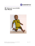
1
Q0 User Manual
047-9900 User Manual Q0 Dummy Rev B
© 2011 Humanetics Innovative Solutions
Page 1 of 41
For information on Humanetics products, please visit our web site at www.humaneticsatd.com
or contact:
Humanetics Innovative Solutions
47460 Galleon Drive
Plymouth, MI 48170, USA
Telephone: 734-451-7878
Fax: 734-451-9549
No part of this publication may be reproduced, stored in a retrieval system or transmitted in any
form or by any means, electronic, photocopying, recording, mechanical or otherwise, without the
express written consent of Humanetics Innovative Solutions.
Copyright © 2011 Humanetics Innovative Solutions, All rights reserved.
The information in this manual is furnished for informational use only, and is subject to change
without notice. Humanetics Innovative Solutions assumes no responsibility or liability for any
errors or inaccuracies that may appear in this manual.
047-9900 User Manual Q0 Dummy Rev B
© 2011 Humanetics Innovative Solutions
Page 2 of 41
List of Contents
CHAPTER 1 - General ................................................................................................... 5 1.1 Summary .............................................................................................................. 5 1.2 Disclaimers ........................................................................................................... 5 1.3 Introduction ........................................................................................................... 5 CHAPTER 2 - Design Description .................................................................................. 7 2.1 Introduction ........................................................................................................... 7 2.2 Head ..................................................................................................................... 8 2.3 Neck...................................................................................................................... 9 2.4 Shoulder and Arms ............................................................................................. 10 2.5 Thorax................................................................................................................. 11 2.6 Lumbar Spine ..................................................................................................... 12 2.7 Pelvis and Legs .................................................................................................. 13 2.8 Rubber Suit ......................................................................................................... 13 2.9 Tools ................................................................................................................... 14 2.10 Main Dummy Characteristics .............................................................................. 14 CHAPTER 3 - Instrumentation ..................................................................................... 16 3.1 Introduction ......................................................................................................... 16 3.2 Overview of Instrumentation ............................................................................... 16 3.3 Head ................................................................................................................... 17 3.4 Neck.................................................................................................................... 18 3.5 Thorax................................................................................................................. 19 3.6 Pelvis .................................................................................................................. 20 CHAPTER 4 - Disassembly and Assembly .................................................................. 21 4.1 Introduction ......................................................................................................... 21 4.2 Suit ..................................................................................................................... 22 4.3 Head ................................................................................................................... 22 4.4 Neck.................................................................................................................... 23 4.5 Shoulder and Arms ............................................................................................. 24 4.6 Thorax................................................................................................................. 24 4.7 Lumbar Spine ..................................................................................................... 25 4.8 Pelvis and Legs .................................................................................................. 26 CHAPTER 5 - Certification ........................................................................................... 27 5.1 Introduction ......................................................................................................... 27 5.2 Certification Equipment ....................................................................................... 27 5.3 Head ................................................................................................................... 28 5.4 Neck .................................................................................................................... 31 5.5 Lumbar Spine ..................................................................................................... 38 CHAPTER 6 - Handling Procedures and Application ................................................... 39 6.1 Introduction ......................................................................................................... 39 6.2 Handling Procedures .......................................................................................... 39 6.3 Storage of Q0 Child Dummy ............................................................................... 39 6.4 Application in Impact Tests ................................................................................. 39 CHAPTER 7 - References............................................................................................ 41 047-9900 User Manual Q0 Dummy Rev B
© 2011 Humanetics Innovative Solutions
Page 3 of 41
List of Figures
Figure 1: Q0 newborn child dummy representing a six weeks old baby ........................... 6 Figure 2: Q0 child dummy in parts.................................................................................... 7 Figure 3: Q0 child dummy head components - head mould, upper neck load cell
replacement and accelerometer mounting bracket and two sets of interface
attachment bolts ................................................................................................ 8 Figure 4: Q0 child dummy head in top, side, front and bottom view ................................. 9 Figure 5: Q0 child dummy neck - neck moulded rubber with two end plates and two
intermediate disks, neck cable with washers and nut and two sets of interface
attachment bolts. ............................................................................................. 10 Figure 6: Q0 child dummy shoulder bracket, arms, arm attachment bolts and shoulder to
spine attachment bolts .................................................................................... 10 Figure 7: Q0 child dummy thoracic spine (spine colour may be black)........................... 11 Figure 8: Q0 child dummy torso flesh foam .................................................................... 12 Figure 9: Q0 child dummy lumbar spine ......................................................................... 13 Figure 10: Q0 child dummy pelvis bracket and legs ..................................................... 13 Figure 11: Q0 child dummy suit .................................................................................... 14 Figure 12: Q0 child dummy instrumentation scheme .................................................... 17 Figure 13: Q0 child dummy head and neck instrumentation location............................ 18 Figure 14: Q0 child dummy upper neck load cell (FTSS IF-217) .................................. 19 Figure 15: Q0 child dummy thorax and pelvis instrumentation location ........................ 20 Figure 16: Head drop table test set-up and Q0 child dummy head in harness (pictures do
not show correct drop height and drop angle) ............................................. 29 Figure 17: Q0 head drop tests Left: Frontal test: 130 ± 1 mm, 28 ± 1. Right: Lateral test:
130 ± 1 mm, 35 ± 1. .................................................................................. 30 Figure 18: Q0 child dummy head drop test result ......................................................... 31 Figure 19: Q0 child dummy neck in pendulum test set-up (felxion) .............................. 32 Figure 20: Q0 neck pendulum test mounting equipment .............................................. 32 Figure 21: Q0 child dummy neck flexion test set-up (arrow indicates position of neck slits,
forward side of the neck) ............................................................................. 34 Figure 22: Q0 child dummy neck extension test set-up (arrow indicates position of neck
slits, forward side of the neck) ..................................................................... 34 Figure 23: Q0 child dummy neck lateral flexion test set-up (head 90 degrees turned to
obtain symmetric neck loading, arrow indicates position of neck slits, forward
side of the neck) .......................................................................................... 35 Figure 24: Q0 child dummy neck flexion performance (provisional corridor indicate: 3.7 to
5.2 Nm at 60 degrees) ................................................................................. 37 Figure 25: Q0 child dummy neck extension performance (provisional corridor indicate: -0.5
to -2.0 Nm at -50 degrees) ........................................................................... 37 Figure 26: Q0 child dummy neck lateral flexion performance (provisional corridor indicate:
+-0.5 to +-2.0 Nm at +-40 degrees) ............................................................. 38 Figure 27: Q0 child dummy in child restraint sled tests at TNO Left: Frontal impact test
Right: Side impact test with moving door ..................................................... 40 047-9900 User Manual Q0 Dummy Rev B
© 2011 Humanetics Innovative Solutions
Page 4 of 41
CHAPTER 1 - General
1.1
Summary
This document presents guideline for test engineers and dummy technicians to utilise the
dummy in accident reconstruction crash test with in the CHILD-project. Within the CHILDproject the Q0 dummy is developed as a member of the Q-series child dummies. The Q0
dummy represents a 6 weeks old newborn child. The dummy is developed to be used in
appropriate child restrained systems en car beds.
Information is provided about the design, instrumentation, assembly and disassembly,
performance check and optioning, as well as performance criteria.
The early stage of development of the Q0 dummy results in the lack of sound and settled
procedures for certification and handling, therefore it is stressed that this document can not be
considered as a manual. The user is invited to submit comment and feedback about the
content of this document as well as on the use of the dummy to the TNO. The feedback
received can assist us to further improve the dummy design and its documentation.
1.2
Disclaimers
This document is made for the partners in the consortium of the European Commission
funded CHILD-project. It must be read as user guidelines to support the use of the Q0 dummy
in the accident reconstruction test within the project. The purpose of the document is to
support the Q0 dummy utilisation by partners in the CHILD-project. The user of this manual is
invited to provide TNO with his feedback and comment on the content of this manual and the
use of the Q0 child dummy.
The decision to expose the dummy to a certain crash scenarios belongs to the responsibility
of the partners that specify the test condition. TNO does not accept any responsibility of
damage due to application of the Q0 dummy beyond its design conditions.
1.3
Introduction
The Q0 child dummy (see Figure 1) is designed as a tool to evaluate the protection offered to
newborn children and babies by an appropriate child restraints used in cars as specified in the
restraint manual in frontal, rear and side impact and rollover crash conditions. The dummy
design is suitable for use in the standard EuroNCAP and ECE R44 child restraint evaluation
test procedures. In the current evaluation test procedures the P0 dummy is specified. This
dummy allows only a qualitative assessment of the protection in terms of remaining of the
dummy in the child restraint as well as not exceeding certain specified space envelops. The
Q0 dummy enables besides the qualitative aspect also a quantitative assessment of the
safety through the data obtained by the built in instrumentation. The measurement capabilities
of the Q0 dummy make it suitable for application in accident scenario research.
047-9900 User Manual Q0 Dummy Rev B
© 2011 Humanetics Innovative Solutions
Page 5 of 41
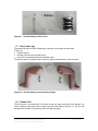
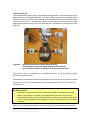
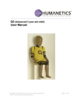
Figure 1:
Q0 newborn child dummy representing a six weeks old baby
047-9900 User Manual Q0 Dummy Rev B
© 2011 Humanetics Innovative Solutions
Page 6 of 41
CHAPTER 2 - Design Description
2.1
Introduction
The Q0 newborn child dummy represents a six weeks old baby. The mass en inertia are
based on the anthropomorphic data collection called CANDAT [1]. The total mass of the
dummy, including suit is 3.4 {± 0.05} kg.
In this chapter a description of the Q0 child dummy design is given.
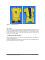
Figure 2:
Q0 child dummy in parts
047-9900 User Manual Q0 Dummy Rev B
© 2011 Humanetics Innovative Solutions
Page 7 of 41
2.2
Head
The head of the Q0 child dummy comprises of three parts and two sets of bolts (Figure 3):
a Polyurethane (PU) core covered with a bonded vinyl (PVC) skin.
an upper neck load cell
an accelerometer mounting bracket.
four head to upper neck load cell attachment screws (countersunk screws)
four upper neck load cell neck to accelerometer mounting bracket attachment screw
(hexagon-socket screws)
The head outer shape is suitable to accept impacts from any direction and has featureless
face. In the head core a large cavity provides accommodation for the upper neck load cell and
the head accelerometer-mounting bracket (see Figure 4). The upper neck load cell, the
accelerometer mounting bracket and two sets of interface attachment bolts (head to load cell
and load cell to accelerometer mounting) belong the to the head mass.
Figure 3:
Q0 child dummy head components - head mould, upper neck load cell
replacement and accelerometer mounting bracket and two sets of interface
attachment bolts
047-9900 User Manual Q0 Dummy Rev B
© 2011 Humanetics Innovative Solutions
Page 8 of 41
Figure 4:
2.3
Q0 child dummy head in top, side, front and bottom view
Neck
The neck of the Q0 child dummy comprises of two parts and two sets of bolts (Figure 5):
a neck mould that includes two end plates and two intermediate disks
a neck cable with washers and nut
four accelerometer mounting bracket to neck attachment screws (countersunk screws)
four neck to shoulder plate attachment screws (hexagon-socket screws)
047-9900 User Manual Q0 Dummy Rev B
© 2011 Humanetics Innovative Solutions
Page 9 of 41
The neck mould has two steel end plates with threaded holes to attach the neck to the head
and the thorax and two aluminium intermediate disks. The three rubber sections in the neck
are equipped with transverse holes and slits at the front side. These incisions are applied to
decrease the bending stiffness of the neck in the extension (rearward) bending mode. The
neck cable protects the rather fragile neck for tension loads that may be too sever in
combination with extensive bending.
Figure 5:
2.4
Q0 child dummy neck - neck moulded rubber with two end plates and two
intermediate disks, neck cable with washers and nut and two sets of
interface attachment bolts.
Shoulder and Arms
The shoulder and arms of the Q0 child dummy comprise of three parts and some bolts (Figure
6):
a shoulder bracket
two arms (left hand and right hand one)
two arm to shoulder attachment bolts (shoulder bolts)
four shoulder to thoracic spine attachment screws (countersunk screws)
The shoulder bracket serves also as the top plate on the polyurethane thoracic spine.
Figure 6:
Q0 child dummy shoulder bracket, arms, arm attachment bolts and
shoulder to spine attachment bolts
047-9900 User Manual Q0 Dummy Rev B
© 2011 Humanetics Innovative Solutions
Page 10 of 41
2.5
Thorax
The Q0 child dummy thorax comprises of three parts and a set of interface attachment bolts
a polyurethane thoracic spine
a lower thoracic spine end plate
four shoulder to thoracic spine attachment screws (countersunk screws)
a torso flesh foam part covered with vinyl skin
The polyurethane thoracic spine is equipped with recesses at the top and bottom end that
allow the insertion of screws to attach the neck and lumbar spine. A recess at the rear side
allows the application of thoracic accelerometers.
The torso flesh is cut at the rear side to allow the insertion of the complete pelvis-lumbar
spine-thoracic spine-shoulder-neck assembly.
Figure 7:
Q0 child dummy thoracic spine (spine colour may be black)
047-9900 User Manual Q0 Dummy Rev B
© 2011 Humanetics Innovative Solutions
Page 11 of 41
Figure 8:
2.6
Q0 child dummy torso flesh foam
Lumbar Spine
The lumbar spine of the Q0 child dummy comprises of two parts and two sets of bolts (Figure
9):
a lumbar spine mould that includes two end plates and two intermediate disks
a lumbar spine cable with washers and nut
four lower thoracic end plate to lumbar spine attachment screws (hexagon-socket screws)
four lumbar spine to pelvis bracket attachment screws (countersunk screws)
The lumbar spine assembly is identical to the neck assembly.
The lumbar spine mould has two steel end plates with threaded holes to attach the lumbar
spine to the thorax and the pelvis bracket and two aluminium intermediate disks. The three
rubber sections in the lumbar spine are equipped with transverse holes and slits as required
to decrease the bending stiffness of the neck in the extension (rearward) bending mode. The
lumbar spine is mounted in the dummy with the slits at the rear side. The lumbar spine cable
protects the rather fragile moulded part for tension loads.
047-9900 User Manual Q0 Dummy Rev B
© 2011 Humanetics Innovative Solutions
Page 12 of 41
Figure 9:
2.7
Q0 child dummy lumbar spine
Pelvis and Legs
The pelvis and legs of the Q0 child dummy comprise of three parts and two bolts
(Figure 10):
a pelvis bracket
two legs (left hand and right hand one)
two pelvis to leg attachment bolts (shoulder bolts)
The pelvis bracket is equipped with a recess for pelvis accelerometers at the rear side.
Figure 10: Q0 child dummy pelvis bracket and legs
2.8
Rubber Suit
The Q0 dummy is provided with a suit that covers the upper arms with short sleeves, the
thorax, abdomen and pelvis and the upper legs with short sleeves (Figure 11). The suit can
be opened at the back of the dummy with hook-and-loop-band.
047-9900 User Manual Q0 Dummy Rev B
© 2011 Humanetics Innovative Solutions
Page 13 of 41
Figure 11: Q0 child dummy suit
2.9
Tools
The Q0 child dummy is supplied without special tools for disassembly and assembly. The
dummy can be disassembled and assembled with standard tools like Allen-keys (2.5, 3 and 4
mm) flat end screwdriver (width 5 mm) and a box-wrench (8 mm). To reach the thoracic spine
to neck and the thoracic spine to lumbar spine attachment screws an Allen-key with an
reduced short end can be helpful.
2.10 Main Dummy Characteristics
This section will describe some of the main Q0 child dummy characteristics with regards the
mass and principle dimensions.
In Table 1 the masses of the main Q0 dummy components are given. A detailed description of
the parts considered per component is presented.
047-9900 User Manual Q0 Dummy Rev B
© 2011 Humanetics Innovative Solutions
Page 14 of 41
Table 1:
Q0 child dummy component masses
Component
Mass in kg
Principle Content
Head and neck
1.10 ± 0.10
Head, upper neck load cell accelerometer
mounting bracket, neck assembly and 3 sets of
screws
Arms (each)
0.14 ± 0.015
Arm and shoulder screw
Torso
1.50 ± 0.15
Shoulder bracket, thoracic spine, thoracic spine
end plate, lumbar spine, pelvis bracket and 5
sets of bolts
Legs (each)
0.290 ± 0.03
Leg and shoulder screw
Total
3.46 ± 0.34
(tolerance including instrumentation allowance)
In Table 2 the principle dimensions Q0 dummy are given.
Table 2:
Q0 child dummy dimensions
Dimension
Distance in mm
Sitting height
355 ± 7
Shoulder height
255 ± 5
Shoulder width
145 ± 5
Shoulder top to elbow
100 ± 2
Elbow to hand
127 ± 2
Buttock to knee
130 ± 5
Knee to foot
112 ± 2
047-9900 User Manual Q0 Dummy Rev B
© 2011 Humanetics Innovative Solutions
Page 15 of 41
CHAPTER 3 - Instrumentation
3.1
Introduction
In this chapter the instrumentation option of the Q0 child dummy are presented.
Section 3.1 an overview of the instrumentation options is given. The subsequent sections
describe the instrumentation options per body part.
The Q0 child dummy allows the application of 15 instrument channels.
For all instrumentation channels a channel filter class according to ISO 6487: 2000 or SAE
J211 (March 1995) is recommended.
3.2
Overview of Instrumentation
The Q0 dummy is designed to accept the following instrumentation options (see also Figure
12):
Head:
Three uni-axial accelerometers in the centre of gravity of the head
Ax, Ay, Az (forward, lateral, downward)
Neck:
Upper neck load cell for three force and three moment channels
Fx, Fy, Fz (forward, lateral, downward)
Mx, My, Mz (RH ear down, nose up, nose right)
Thorax: Three uni-axial accelerometers at about the T4 location
Ax, Ay, Az (forward, lateral, downward)
Pelvis: Three uni-axial accelerometers at about the sacrum location
Ax, Ay, Az (forward, lateral, downward)
047-9900 User Manual Q0 Dummy Rev B
© 2011 Humanetics Innovative Solutions
Page 16 of 41
Upper neck load cell
Fx, Fy, Fz, Mx, My, Mz
Head accelerations
Ax, Ay, Az
Thorax accelerations
Ax, Ay, Az
Pelvis accelerations
Ax, Ay, Az
Figure 12: Q0 child dummy instrumentation scheme
3.3
3.3.1
Head
Accelerations
Three uni-axial accelerometers can be mounted in the accelerometer-mounting bracket
located on top of the neck. The mounting bracket is equipped with a recess at the centre of
gravity of the head that can accommodate a small block with three uni-axial accelerometers.
One accelerometer (Ax) is aligned with its sensitive axis parallel to the horizontal head-neck
interface in the mid-sagittal plane. The second accelerometer (Ay) is aligned with its sensitive
axis parallel to the horizontal head-neck interface and perpendicular to the mid-sagittal plane.
The third accelerometer (Az) is aligned with its sensitive axis perpendicular to the horizontal
head-neck interface in the mid-sagittal plane.
Appropriate transducers are the Endevco model 7264A and Entran EGAS-500 or Endevco
model 7264A-2000 and Kyowa ASM-200BA uni-axial accelerometers.
The small
accelerometer-mounting block should be adapted to the used type of transducer.
A Channel Filter Class of 1000 according to ISO 6487 or SAE J211 is recommended for the
head acceleration signals.
047-9900 User Manual Q0 Dummy Rev B
© 2011 Humanetics Innovative Solutions
Page 17 of 41
Load cell centre
(neutral axis)
13 mm
Head CG
(incl. Acc-bracket)
13 mm
20 mm
Head acceleration
Ax, Ay, Az
9.5 mm
Changes 05 January 2006, CW:
Occipital Condyles
(OC-joint)
OC-joint shifted 4 mm down to interface of neck.
Dimension of 20 mm is valid from OC-joint
Dimension of 5.5 mm changed in 9.5 mm
Mass 1176 kg, CG location w.r.t. OC-joint (-6.3 , 0 .0, 19.0)
Figure 13: Q0 child dummy head and neck instrumentation location
3.4
Neck
The head-neck interface is equipped with a 6-axis upper neck load cell. The load cell used in
Q0 is identical to that of the Q3 Dummy.
The capacity specification of this load cell is
Fx =
5 kN (1125 lbf)
Fy =
5 kN (1125 lbf)
Fz =
6 kN (1350 lbf)
Mx = 150 Nm (1325 in-lbf)
My = 150 Nm (1325 in-lbf)
Mz = 80 Nm ( 700 in-lbf)
Appropriate load cells for this application are Denton model 3715 and FTSS IF-217 (see
Figure 14). A structural replacement of the load cell is available.
047-9900 User Manual Q0 Dummy Rev B
© 2011 Humanetics Innovative Solutions
Page 18 of 41
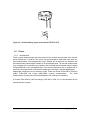
Figure 14: Q0 child dummy upper neck load cell (FTSS IF-217)
3.5
Thorax
3.5.1 Accelerations
Three uni-axial accelerometers can be mounted in the recess at the rear side of the thoracic
spine at about the T4 location. The recess can accommodate a small block with three uniaxial accelerometers. One accelerometer (Ax) is aligned with its sensitive axis parallel to the
horizontal thoracic-lumbar spine interface in the mid-sagittal plane. The second accelerometer
(Ay) is aligned with its sensitive axis parallel to the horizontal thoracic-lumbar spine interface
and perpendicular to the mid-sagittal plane. The third accelerometer (Az) is aligned with its
sensitive axis perpendicular to the thoracic-lumbar spine interface in the mid-sagittal plane.
Appropriate transducers are the Endevco model 7264A and Entran EGAS-500 or Endevco
model 7264A-2000 and Kyowa ASM-200BA uni-axial accelerometers.
The small
accelerometer-mounting block should be adapted to the used type of transducer.
A Channel Filter Class of 1000 according to ISO 6487 or SAE J211 is recommended for the
head acceleration signals.
047-9900 User Manual Q0 Dummy Rev B
© 2011 Humanetics Innovative Solutions
Page 19 of 41
Thorax accelerations
Ax, Ay, Az
Pelvis accelerations
Ax, Ay, Az
78.5 mm
54 mm
18.5 mm
Figure 15: Q0 child dummy thorax and pelvis instrumentation location
3.6
3.6.1
Pelvis
Accelerations
Three uni-axial accelerometers can be mounted in the recess at the rear side of the pelvis
bracket at sacrum location. The recess can accommodate a small block with three uni-axial
accelerometers. One accelerometer (Ax) is aligned with its sensitive axis parallel to the
horizontal lumbar spine-pelvis interface in the mid-sagittal plane. The second accelerometer
(Ay) is aligned with its sensitive axis parallel to the horizontal lumbar spine-pelvis interface
and perpendicular to the mid-sagittal plane. The third accelerometer (Az) is aligned with its
sensitive axis perpendicular to the lumbar spine-pelvis interface in the mid-sagittal plane.
Appropriate transducers are the Endevco model 7264A and Entran EGAS-500 or Endevco
model 7264A-2000 and Kyowa ASM-200BA uni-axial accelerometers.
The small
accelerometer-mounting block should be adapted to the used type of transducer.
A Channel Filter Class of 1000 according to ISO 6487 or SAE J211 is recommended for the
head acceleration signals.
047-9900 User Manual Q0 Dummy Rev B
© 2011 Humanetics Innovative Solutions
Page 20 of 41
CHAPTER 4 - Disassembly and Assembly
4.1
Introduction
The disassembly and assembly of the Q0 child dummy is described in this chapter.
Disassembly may be necessary in order to check, certify or repair the dummy or its parts. The
parts are usually be assembled in reversed order described for disassembly. Some remarks
and instructions important for assembly are given.
4.1.1 Required Tools
The Q0 child dummy is a metric design. No special tools are required for disassembly and
assembly. The standard tools to be used for disassembled and assembled are:
Allen-keys (2.5, 3.0 and 4.0 mm)
Flat end screwdriver (width 3.5 mm)
Box-wrench (8 mm across flats).
To reach the thoracic spine to neck and the thoracic spine to lumbar spine attachment screws
an Allen-key with an reduced short end or ball-head Allen-keys can be helpful.
4.1.2 Fasteners List
In Table 3 the fasteners are listed. Indicated are the body part, fastener location, size and
quantity.
Table 3:
Body Part
Head
Fasteners List
Location
Size
Quantity
Head to upper neck load cell
M5x12 c'sunk head
4
Upper neck load cell to
accelerometer mounting bracket
Accelerometer mounting bracket to
upper neck
Lower neck to shoulder bracket
Neck cable
M5x16 socket head
4
M4x10 c'sunk head
4
M4x14 socket head
M5 nut self-locking
4
1
Shoulder
and arms
Arms to shoulder bracket
Shoulder bracket to thoracic spine
M5x38 shoulder screw
M4x10 c'sunk head
2
4
Thorax
Thoracic spine to lower thoracic
spine end plate
Lower thoracic spine end plate to
upper lumbar spine
Lumbar spine cable
Lower lumbar spine to pelvis bracket
M4x10 c'sunk head
4
M4x14 socket head
4
M5 nut self-locking
M4x10 c'sunk head
1
3
Legs to pelvis bracket
M5x30 shoulder screw
2
Neck
Lumbar
spine
Pelvis and
legs
047-9900 User Manual Q0 Dummy Rev B
© 2011 Humanetics Innovative Solutions
Page 21 of 41
4.2
Suit
All disassembly tasks with the Q0 child dummy, except the disassembly of the head, require
stripping off the suit from the dummy
1. Open the hook-and-loop-band splice in the Q0 child dummy rubber suit.
2. Remove the rubber suit by stripping off.
Assembly remark or instruction:
After assembly of the dummy up to and inclusive the neck of the shoulder bracket the suit can
be put on. It is recommended to turn the suit inside out.
Turn the suit inside out
Put the trouser legs on the dummy legs with the edges up to just above the knees.
Strip the suit trousers over the buttock of the dummy.
Put the suit sleeves on the dummy arms with the edges up to just above the elbows.
Strip the suit body over the shoulders.
Rotate the arms and legs a few times 30 degrees up and down for a correct settlement of
the suit on the arms and legs.
4.3
Head
To remove the head from the Q0 child dummy the four M5x16 socket head screws accessible
from the top of the head should be unscrewed. With these fasteners the head and upper neck
load cell combination is separated from the accelerometer-mounting bracket that remains
attached to the neck. To separate the upper neck load cell from the head, unscrew the four
M5x16 countersunk screws that attach the load cell inside the blind recess in the head. The
accelerometer-mounting bracket can be disassembled from the neck by unscrewing the four
M4x10 countersunk screws.
1. Remove head and upper neck load cell from the accelerometer-mounting bracket by
unscrewing the four M5x16 socket head screws accessible from the top of the head.
2. Remove the upper neck load cell from the blind cavity in the head by unscrewing the four
M5x16 countersunk screws.
3. Remove the accelerometer-mounting bracket from the neck by unscrewing the four
M4x10 countersunk screws.
Assembly remark or instruction:
The three interfaces described above can be mounted in four different directions each.
Caution:
The direction of the head should be forward facing on the body.
047-9900 User Manual Q0 Dummy Rev B
© 2011 Humanetics Innovative Solutions
Page 22 of 41
In case of accelerometer the accelerometer-mounting bracket should be positioned such
the X- and Y-direction sensitive accelerometers are on the correct position.
In case of load cell application the load cell direction should be such that the cable exits
are at the rear side.
4.4
Neck
The neck can be separated from the dummy after the head and accelerometer-mounting
bracket are removed. To reach the lower neck to thoracic spine interface fasteners, the
complete spine should be separated from the torso flesh foam part by removal of the arms
and legs. The neck cable can be removed from the neck moulded part.
1. Remove the head from the accelerometer-mounting bracket and the accelerometermounting bracket from the neck as described in section 4.3 step 1 and 3.
2. Remove the arms from the torso by unscrewing the two M5x38 shoulder bolts.
3. Remove the legs from the torso by unscrewing the two M5x30 shoulder bolts.
4. Open the torso flesh part at shoulder level to release the shoulder bracket from the torso
flesh foam part.
5. Remove the neck, shoulder bracket, thoracic spine, lumbar spine and pelvis bracket
assembly from the torso flesh foam part by carefully pulling it out of the opened torso flesh
foam in upward direction.
6. Remove the neck assembly from the shoulder bracket by unscrewing the four M4x14
socket head screws.
7. Remove the neck cable from the neck moulded part by unscrewing the self-locking nut at
the neck lower side. (Use an 8 mm box -wrench for the nut and hold the threaded end of
the spine cable with a flat end screwdriver (width 3.5 mm).
Assembly remark or instruction:
Caution:
The neck cable should be assembled without any pretension. If the cable is too long the
use of washers underneath the nut is allowed to fill the gap.
The neck assembly should be mounted with the slits in its rubber sections on the forward
side. A locator pin in the shoulder bracket prevents faulty assembly of the neck on top of
the shoulder bracket.
Note: The neck assembly is identical to the lumbar spine assembly the neck however is a
part critical for the dummy performance, certification requirements are applicable for
this part.
047-9900 User Manual Q0 Dummy Rev B
© 2011 Humanetics Innovative Solutions
Page 23 of 41
4.5
Shoulder and Arms
The arms can easily be removed by unscrewing the two M5x38 shoulder screws. The
shoulder bracket can be separated from the dummy after the removal of the neck (see section
4.4).
1. Remove the neck (or the head neck assembly in case the head is not disassembled) from
the dummy as described in section 4.4 steps 2 to 6.
2. Remove the shoulder bracket from the thoracic spine by unscrewing the four M4x10
countersunk screws.
Assembly remark or instruction:
Caution:
The shoulder bracket should be mounted with its locator pin at the forward side. The
locator pin protrudes at both sides of the shoulder bracket. A hole in the thoracic spine
topside prevents faulty assembly of the shoulder bracket.
Note: The topside of the thoracic spine is the bend cylindrical side.
4.6
Thorax
The thoracic spine assembly can be separated from the dummy after removal of the shoulder
bracket (see section 4.5) and removal of the lumbar spine. The lower thoracic spine end plate
can be removed from the thoracic spine by unscrewing the four M4x10 countersunk screws.
1. Remove the shoulder bracket from the thoracic spine as described in section 4.5 steps 1
to 3.
2. Remove the thoracic spine assembly from the lumbar spine by unscrewing the four M4x14
socket head screws.
3. Remove the lower thoracic spine end plate from the thoracic spine by unscrewing the four
M4x10 countersunk screws.
Assembly remark or instruction:
Caution:
The thoracic spine end plate should be mounted with its locator pin at the rear side. The
locator pin protrudes at both sides of the thoracic spine end plate. A hole in the thoracic
spine bottom side prevents faulty assembly of the thoracic spine end plate.
Note: The bottom side of the thoracic spine is the straight cylindrical side.
047-9900 User Manual Q0 Dummy Rev B
© 2011 Humanetics Innovative Solutions
Page 24 of 41
4.7
Lumbar Spine
The lumbar spine assembly can be separated from the dummy after the thoracic spine
assembly is removed (see section 4.6). The lumbar spine cable can be removed from the
lumbar spine moulded part.
1. Remove the thoracic spine assembly as described in section 4.6 step 1 and 2.
2. Remove the lumbar spine assembly from the pelvis bracket by unscrewing the four M4x14
socket head screws.
3. Remove the lumbar sine cable from the lumbar spine moulded part by unscrewing the
self-locking nut at the neck lower side. (Use an 8 mm box -wrench for the nut and hold the
threaded end of the spine cable with a flat end screwdriver (width 3.5 mm).
047-9900 User Manual Q0 Dummy Rev B
© 2011 Humanetics Innovative Solutions
Page 25 of 41
Assembly remark or instruction:
Caution:
The lumbar spine cable should be assembled without any pretension. If the cable is too
long the use of washers underneath the nut is allowed to fill the gap.
The lumbar spine should be mounted with the slits in its rubber sections on the rear side.
A locator pin in the thoracic spine end plate prevents faulty assembly of the lumbar spine
on the lower thoracic end plate.
Note: The lumbar spine assembly is identical to the neck assembly the lumbar spine
however is not a part critical for the dummy performance, no certification requirements
are applicable for this part.
4.8
Pelvis and Legs
The legs can easily be removed by unscrewing the two M5x30 shoulder screws. The pelvis
bracket can be separated from the dummy after the removal the complete spine from the
torso flesh foam part.
1. Remove the legs from the torso by unscrewing the two M5x30 shoulder bolts.
2. Remove the arms from the torso by unscrewing the two M5x38 shoulder bolts.
3. Open the torso flesh part at shoulder level to release the shoulder bracket from the torso
flesh foam part.
4. Remove the neck, shoulder bracket, thoracic spine, lumbar spine and pelvis bracket
assembly from the torso flesh foam part by carefully pulling it out of the opened torso flesh
foam in upward direction.
5. Remove the pelvis bracket from the lumbar spine assembly by unscrewing the three
M4x10 countersunk screws.
Assembly remark or instruction:
Caution:
The pelvis bracket should be mounted with its accelerometer cavity to the rear side.
If the pelvis bracket is not correctly mounted the legs will not fit properly
Note:
The slits in its rubber sections of the lumbar spine are at the rear side.
047-9900 User Manual Q0 Dummy Rev B
© 2011 Humanetics Innovative Solutions
Page 26 of 41
CHAPTER 5 - Certification
5.1
Introduction
The certification procedures to verify the performance of the Q0 child dummy are primarily
based on the use of standard Part 572 equipment [2].
Depending on the side to be impacted, dummy parts should be certified for frontal, rear or left
hand or right hand side impact. It is recommended to verify the Q0 child dummy performance
for all direction each time a certification is desired or required.
The certification tests on the Q0 child dummy deal only with head and neck.
Head: a free-fall drop test with the side of the head impacting a flat rigid surface.
Equipment needed is similar to equipment used in Part 572 subpart E;
Neck: tests with a Part 572 subpart E neck pendulum using the Q0 child head form
and ES-2 interface, causing lateral flexion, as well as rotation and translation of the
neck top interface;
Note:
As the lumbar spine is identical to the neck the performance of the part can be verified
in the same way as the neck. However there are no performance requirements
applicable for the lumbar spine.
In the current stage of dummy development no certification requirements as commonly known
from other dummy are set yet. In this chapter the performance verification tests of the design
phase are documented to enable the check on consistent dummy performance. In a later
stage of development proper pass / fail criteria will be established to verify the dummy
performance.
5.2
Certification Equipment
The certification equipment required for the performance verification of the Q0 child dummy is
given below. A detailed description of the application of the equipment is given in the section
that deals with the procedure.
Head Drop Test
For the free-fall head drop test a support and release mechanism, as well as a rigid, flat
impact surface is necessary. The release mechanism and impact surface can be similar to
that of the Standard Part 572 subpart E head drop test [2]. The Q0 head is suspended to the
release mechanism with a simple rope harness. No special dummy-dedicated equipment is
required for the Q0 head certification. In Figure 16 the head drop test set-up and the head
suspension harness is shown.
047-9900 User Manual Q0 Dummy Rev B
© 2011 Humanetics Innovative Solutions
Page 27 of 41
Neck Bending Tests
For the neck and lumbar spine tests, a pendulum is required similar to the Standard Part 572
subpart E, neck-bending pendulum [2]. The pendulum is decelerated by aluminium
honeycomb (crush strength 1.8 lbs./cu. ft).
List of special equipment:
Q3 pendulum mounting base
Standard Q3 upper neck load cell replacement
Modified accelerometer mounting bracket
(centric hole 15 mm to accommodate the neck cable nut)
Special bracket the replaces the accelerometer-mounting bracket on top of the neck
(threaded holes to allow application of potentiometer shafts)
Modified Q0 head
(holes at both side to allow protrusion of the potentiometer shafts)
Two potentiometer hardware as used for Hybrid III neck certification tests
Shaft, potentiometer housing and bolt (on opposite side for mass compensation)
Upper neck load cell mounted in the head
5.3
Head
5.3.1 Introduction
The head should be visually inspected for damage to the skin or core.
5.3.2 Test set-up
This test has to be conducted using the complete head assembly. The head consisting of the
head, the upper neck load cell structural replacement and the accelerometer-mounting
bracket (see Figure 3). The head has to be instrumented with three uni-axial accelerometers
mounted on an accelerometer-mounting block located on the accelerometer-mounting
bracket.
Accelerations are to be filtered using ISO 6487 or SAE J211 Channel Filter Class 1000.
The head must be positioned with a 130 ± 0.25 mm spacing above a flat, rigid impact surface,
as described in Part 572 subpart E (surface finish between 8 and 80 micro-inches). The
impact surface must be horizontal.
A 'quick release' mechanism is required to drop the head on the impact surface. The Q0 head
is suspended to the release mechanism with a simple rope harness. No special dummydedicated equipment is required for the Q0 head certification. In Figure 16 the head drop test
set-up and the head suspension harness is shown.
047-9900 User Manual Q0 Dummy Rev B
© 2011 Humanetics Innovative Solutions
Page 28 of 41
Figure 16: Head drop table test set-up and Q0 child dummy head in harness
(pictures do not show correct drop height and drop angle)
Three test are to be performed one frontal impact and two lateral impacts, one at each side.
Frontal Impact
The head has to be oriented such that the forehead is impacted. The angle between the head
Z-axis and the impact surface shall be 28 ± 1. The mid-sagittal plane of the head shall be
vertical ± 1 (see Figure 17).
Lateral Impact at both sides
The head has to be oriented such that its mid-sagittal plane has an angle of 35 ± 1 with the
impact surface and its anterior-posterior axis is horizontal ± 1 (see Figure 17).
047-9900 User Manual Q0 Dummy Rev B
© 2011 Humanetics Innovative Solutions
Page 29 of 41
28° ± 1°
35° ± 1°
130 ± 1 mm
Figure 17: Q0 head drop tests
Left:
Frontal test:
Right: Lateral test:
130 ± 1 mm
130 ± 1 mm, 28 ± 1.
130 ± 1 mm, 35 ± 1.
Change 24 January 2006, CW:
Check on impact direction
Check in frontal test the lateral and in lateral test the frontal component. This component
must be small to ensure that the impact direction is correct
5.3.3 Requirements
The head passes the test if the peak resultant head acceleration is between:
91 g and 157 g for frontal impact and between 94 g and 162 g for lateral impact.
These requirement corridors are equivalent to the biomechanical requirements set for the Q0
child dummy design.
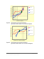
5.3.4 Prototype compliance achieved
To indicate the head drop test performance achieved with the prototype QO child dummy the
results are shown in Figure 18
047-9900 User Manual Q0 Dummy Rev B
© 2011 Humanetics Innovative Solutions
Page 30 of 41
Head drop test results
Resultant peak acceleration in [G]
200
150
100
Corridor Q0 frontal
Q0 Frontal 130 mm
50
Corridor Q0 lateral
Q0 Lateral 130 mm
0
0
50
100
150
200
Head drop height in [mm]
Figure 18:
5.4
Q0 child dummy head drop test result
Neck
5.4.1 Introduction
The neck should be disassembled from the dummy (see section 4.4) and be visually
inspected on cracks or tears in the moulded rubber part.
A dynamic calibration test using the Part 572 subpart E pendulum and some special part s as
listed in section 5.2.
5.4.2 Test set-up
The neck should be kept in the test room for a period of at least four hours prior of a test at a
temperature between 18C and 22C and humidity of 10 to 70 %.
A test set- up overview with the complete assembled set configuration ready for a flexion test is
shown in Figure 19. The special equipment used in the neck tests is shown in Figure 20.
List of special equipment:
Q3 pendulum mounting base
Standard Q3 upper neck load cell replacement
Modified accelerometer mounting bracket
(centric hole 15 mm to accommodate the neck cable nut)
Special bracket the replaces the accelerometer-mounting bracket on top of the neck
(threaded holes to allow application of potentiometer shafts)
Modified Q0 head
(holes at both side to allow protrusion of the potentiometer shafts)
Two potentiometer hardware as used for Hybrid III neck certification tests
Shaft, potentiometer housing and bolt (on opposite side for mass compensation)
Upper neck load cell mounted in the head
047-9900 User Manual Q0 Dummy Rev B
© 2011 Humanetics Innovative Solutions
Page 31 of 41
Figure 19: Q0 child dummy neck in pendulum test set-up (felxion)
Potentiometer-housing
(mass compensation)
Head with holes at each side
equipped with upper neck load cell
ACC-mounting bracket replacement
ACC-mounting bracket (modified)
Load cell replacement
Pendulum base plate for Q3
Two-Potentiometer system
(rod fixed in head potentiometer)
Figure 20: Q0 neck pendulum test mounting equipment
047-9900 User Manual Q0 Dummy Rev B
© 2011 Humanetics Innovative Solutions
Page 32 of 41
Test set-up Assembly
The actions to assemble the test set-up are:
Attach the neck to the modified accelerometer-mounting brackets (see Figure 20).
Make sure that orientation of the neck on the upper accelerometer-mounting
bracket replacement is appropriate for the desired test-mode.
(Threaded holes for the potentiometer shafts must be at the sides)
Attach the modified accelerometer-mounting brackets the appropriate load cell
(replacement) interfaces.
Lower side of the neck (with neck cable nut) to the load cell replacement
Upper side of the neck to the head load cell combination.
Make sure that orientation of the neck on the upper neck load cell is
correct. The cable exit shall be at the opposite side of the neck mould slits,
see Figure 21 - flexion, Figure 22 - extension, Figure 23 - lateral flexion).
Attach the head to the load cell in the appropriate direction.
- Flexion and extension test with the load cell cable exit at the rear head.
- Lateral flexion test with the head 90 degrees turned, cable exit at the head side
Insert the potentiometer shafts at both sides of the head
Attach the head, neck and interface parts assembly to the pendulum base plate.
Make sure that orientation of the set-up on the pendulum base plate is
appropriate for the desired test-mode.
Mount the whole combination in the appropriate direction to the part 572 neck pendulum.
Install the "two-potentiometer" system the one side of the set-up
The rod between head and pendulum potentiometers should be fixed in
head potentiometer to apply the main inertia loads to the pendulum base plate.
Install a potentiometer housing are something with equivalent mass to the shaft at the
opposite side of the head.
047-9900 User Manual Q0 Dummy Rev B
© 2011 Humanetics Innovative Solutions
Page 33 of 41
The Q0 child dummy neck is quite soft in the armed pendulum position the head neck system
will slightly bend downwards. If the pendulum is release with this initially bend down position,
oscillation of the head neck system is likely to occur at the moment of pendulum impact. To
prevent this undesired oscillation the head is taped to a support rod in a "zero bending"
position with a piece of pre-ripped paper tape (see Figure 19).
Flexion Test
In the flexion test the slits in the moulded rubber segments of the neck shall be at the impact
side of the pendulum. (See Figure 21)
Figure 21:
Q0 child dummy neck flexion test set-up
(arrow indicates position of neck slits, forward side of the neck)
Extension Test
In the extension test the slits in the moulded rubber segments of the neck shall be the nonimpact side of the pendulum. (See Figure 22)
Figure 22:
Q0 child dummy neck extension test set-up
(arrow indicates position of neck slits, forward side of the neck)
047-9900 User Manual Q0 Dummy Rev B
Page 34 of 41
© 2011 Humanetics Innovative Solutions
Lateral Flexion Test
In the Lateral flexion test the slits in the moulded rubber segments of the neck shall be at the
potentiometer or non-potentiometer side. To prevent rotation of the head in the lateral flexion
test due to the centre of gravity offset from the neck centreline, the head is turned 90 degrees.
In this way the neck is symmetrically loaded by the head mass inertia and the twopotentiometer system can be used in the same way as in the flexion and extension test. (See
Figure 23)
Figure 23:
Q0 child dummy neck lateral flexion test set-up
(head 90 degrees turned to obtain symmetric neck loading,
arrow indicates position of neck slits, forward side of the neck)
The period in which the pendulum is in pre-impact position (i.e. not the vertical position)
should not exceed 5 minutes.
The pendulum is released and allowed to fall freely from a height chosen to achieve an impact
velocity of 3.2 ± 0.1 m/s, measured at the centre of the accelerometer, 1657.4 mm from the
pendulum axis.
Change 13 January 2006, CW:
Deceleration pulse
The number of honeycomb cells to be used to decelerate the pendulum in the tests
shown in this manual is not known. Later test show that 16 cells is much too high.
Decrease the number of cells such that a maximum initial neck moment of round about
2 Nm or -2 Nm at between 5 and 10 degrees is reached. (See Figure 24, Figure 25 and
Figure 26)
The head rotation is measured with the two rotational potentiometers using an ISO 6487 or
SAE J211 CFC 1000 hardware filter to acquire the data. The pendulum base and the head
047-9900 User Manual Q0 Dummy Rev B
© 2011 Humanetics Innovative Solutions
Page 35 of 41
potentiometer angle are directly measured during the certification test. The flexion angle of
the head must be determined using the following equation:
= dpendulum + dhead
After this calculation, all rotations are digitally filtered using ISO 6487 or SAE J211 CFC 180.
The pendulum acceleration is also filtered digitally using ISO 6487 or SAE J211 CFC 60.
5.4.3 Requirements
For the Q0 child dummy neck there are no simple certification requirements yet. The
performance requirements used in the design phase are the moment-flexion angle corridors
based on scaled down human neck behaviour. The Q0 child dummy neck complies quite well
with these requirements (see Figure 24, Figure 25 and Figure 26). Based on the actual
performance of the Q0 child dummy prototype neck the following provisional certification
requirements are defined.
Flexion Test
The neck passes the flexion test, if the My moment at OC during the loading phase at a head
flexion of 60 degrees is between 3.7 and 5.2 Nm.
Extension Test
The neck passes the extension test, if the My moment at OC during the loading phase at a
head extension of 50 degrees is between -0.5 and -2.0 Nm.
Lateral Flexion Test
The neck passes the lateral flexion test, if the Mx moment at OC during the loading phase at a
head lateral flexion of extension of ± 40 degrees is between ± 0.5 and ± 2.0 Nm.
5.4.4 Prototype compliance achieved
To indicate the compliance achieved with the prototype QO child dummy neck the results are
shown in Figure 24 - flexion; Figure 25 - extension and Figure 26 - lateral flexion.
047-9900 User Manual Q0 Dummy Rev B
© 2011 Humanetics Innovative Solutions
Page 36 of 41
10
Neck OC bending moment in [Nm]
Corridor Q0
8
32697 F 3.19 m/s
6
4
32698 F 3.19 m/s
2
0
-2
-4
0
10
20
30
40
50
60
70
80
90
100
Head flexion in [degrees]
Figure 24:
Q0 child dummy neck flexion performance
(provisional corridor indicate: 3.7 to 5.2 Nm at 60 degrees)
4
Neck OC bending moment in [Nm]
2
Corridor Q0
0
32694 E 3.24 m/s
-2
-4
32695 E 3.21 m/s
-6
-8
-10
-100 -90
-80
-70
-60
-50
-40
-30
-20
-10
0
Head flexion (-ve = extension) in [degrees]
Figure 25:
Q0 child dummy neck extension performance
(provisional corridor indicate: -0.5 to -2.0 Nm at -50 degrees)
047-9900 User Manual Q0 Dummy Rev B
© 2011 Humanetics Innovative Solutions
Page 37 of 41
10
Neck OC bending moment in [Nm]
Corridor Q0
8
6
32690 L 3.24 m/s
4
32691 L 3.24 m/s
2
0
Note:
Bending to the RH ?
side Symmetrical test
Head position, 90 degr
turned on load cell rear
head at RH side
-2
-4
0
10
20
30
40
50
60
70
80
90
100
Head lateral flexion in [degrees]
Figure 26:
5.5
Q0 child dummy neck lateral flexion performance
(provisional corridor indicate: +-0.5 to +-2.0 Nm at +-40 degrees)
Lumbar Spine
The Q0 child dummy lumbar spine is identical to the neck. The performance of the part can be
verified in the same way as the neck (see section 5.4). However there are no performance
requirements applicable for the lumbar spine.
It is recommended to certify the lumbar spine in according to the same procedure as used for
the neck. In case the lumbar spine certification is skipped it is recommended to clearly label
the lumbar spine "NOT CERTIFIED".
047-9900 User Manual Q0 Dummy Rev B
© 2011 Humanetics Innovative Solutions
Page 38 of 41
CHAPTER 6 - Handling Procedures and Application
6.1
Introduction
The handling procedure for the Q0 child dummy and its endorsed application are presented in
this chapter.
6.2
Handling Procedures
The Q0 child dummy design is robust and does not require special handling procedures. It is
recommended to avoid impact contact with rigid sharp edges that may result in damage to the
skin and the underlying structure.
Prior to a test the Q0 child dummy should be kept in the test room for a period of at least four
hours prior to a test at a temperature between 18C and 22C and humidity of 10 to 70 %.
6.3
Storage of Q0 Child Dummy
When storing the Q0 child dummy between tests, or between a test and certification or vice
versa it is advisable to lay the dummy on its back.
To avoid accelerated ageing of dummy materials the dummy should be kept out of direct sunlight when storing. Storage temperature should be between 10˚ and 30˚ C. Further it is
advisable to make sure that the humidity of the storage environment does not exceed 70 %.
To reduce the risk of corrosion, avoid direct contact between water and dummy parts.
6.4
Application in Impact Tests
The Q0 child dummy (see Figure 1) is designed as a tool to evaluate the protection offered to
newborn children and babies by an appropriate child restraints used in cars as specified in the
restraint manual in frontal, rear and side impact and rollover crash conditions. The dummy
design is suitable for use in the standard EuroNCAP and ECE R44 child restraint evaluation
test procedures. In the current evaluation test procedures the P0 dummy is specified. Th P0
dummy allows only a qualitative assessment of the protection in terms of remaining of the
dummy in the child restraint as well as not exceeding certain specified space envelops. The
Q0 dummy enables besides the qualitative aspect also a quantitative assessment of the
safety through the data obtained by the built in instrumentation. The measurement capabilities
of the Q0 dummy make it suitable for application in accident scenario research.
047-9900 User Manual Q0 Dummy Rev B
© 2011 Humanetics Innovative Solutions
Page 39 of 41
At TNO the dummy performance and response has be evaluate through in a program of 30
sled tests (see Figure 27):
Frontal impact tests with CREST-deceleration pulse
Amax = 34 G ( 5 off)
Frontal impact tests with EuroNCAP-deceleration pulse Amax = 42 G (10 off)
Rear impact tests ECE-44 pulse
Amax = 19 G ( 5 off)
Side impact tests with moving door
Amax = 21 G (10 off)
In these tests the 15 possible measurement channels were recorded. In Table 4 the
maximum obtained values are given.
Figure 27: Q0 child dummy in child restraint sled tests at TNO
Left:
Frontal impact test
Right: Side impact test with moving door
Table 4:
Body part
Head
Upper neck
loads
Thorax
Pelvis
Channel reading maximum or minimum values in TNO sled tests
Parameter
Unit
Ax
Ay
Az
Ares
HIC
Fx
Fy
Fz
Mx
My
Mz
Ax
Ay
Az
Ares
Ax
Ay
Az
Ares
G
G
G
G
N
N
N
Nm
Nm
Nm
G
G
G
G
G
G
G
G
047-9900 User Manual Q0 Dummy Rev B
© 2011 Humanetics Innovative Solutions
Value
70.4
88.7
72.8
96.9
809
616
116
415
8.0
28.6
2.8
68.8
60.2
86.2
96.2
83.7
77.6
124
146
Test case
Rear impact
Side - ECE44
Frontal - NCAP
Side - ECE44
Frontal - NCAP
Frontal - NCAP
Side - ECE44
Rear impact
Side - ECE44
Frontal - NCAP
Side - ECE44
Frontal - NCAP
Side - ECE44
Frontal - NCAP
Frontal - NCAP
Frontal - NCAP
Side - ECE44
Frontal - NCAP
Frontal - NCAP
Page 40 of 41
The decision to expose the dummy to a certain crash scenarios belongs to the responsibility
of the partners that specify the test condition. TNO does not accept any responsibility of
damage due to application of the Q0 dummy beyond its design conditions.
CHAPTER 7 - References
1
CANDAT - Child ANthropomorphic DATabase - Since early 90's in house TNO developed
database that combines data sets available from US, UK, Germany and The Netherlands.
(see TNO-reports 1994: 75161275-B (Twisk, D.); 1994: 94.OR.BV.003/1/DT;
94.OR.BV.025.1/DT and 96.OR.BV.005.2/DT)
2
American Code of Federal Regulation 49 CFR Chapter V Part 572 (10-1-00 Edition)
Manual Update Log
Rev. B, June 2011
Manual changed from FTSS to Humanetics
047-9900 User Manual Q0 Dummy Rev B
© 2011 Humanetics Innovative Solutions
Page 41 of 41