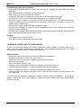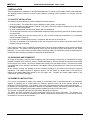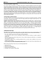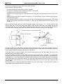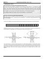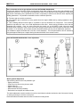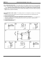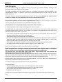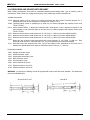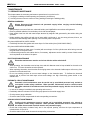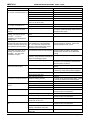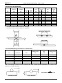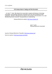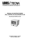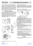
1
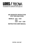
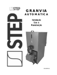
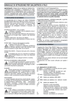
LORS / j
1090 LOUSONS ROAD ♦ UNION, NEW JERSEY 07083 USA
Tel: 908-964-9100 ♦ Fax: 908-964-4492 ♦ email: [email protected]
RESISTANCE SPOT WELDERS
MODELS: 4620N – 4630N
USER MANUAL
DOCUMENT NUMBER: MAN 1037
EDITION: AUGUST 1997
LORS / TECNA
DOCUMENT NUMBER: MAN1037
RESISTANCE SPOT WELDERS: 4620N – 4630N
EDITION: AUGUST 1997
Page 2 / 25
LORS / TECNA
RESISTANCE SPOT WELDERS: 4620N – 4630N
― INDEX ―
CONTENTS
1
2
3
4
PAGE
INTRODUCTION
4
1.1
PRELIMINARY REMARKS
4
1.2
SYMBOLS ON BOTH WELDER AND MANUAL
4
1.3
STANDARD ACCESSORIES
4
TECHNICAL FEATURES
5
2.1
IDENTIFICATION DATA
5
2.2
ELECTRICAL DATA
5
2.3
MECHANICAL DATA
6
2.4
COMPRESSED AIR CONNECTION DATA
6
2.5
COOLING CIRCUIT CONNECTION DATA
6
2.6
ADDITIONAL FEATURES
7
2.7
WELDER MAIN FEATURES
7
2.8
WELDING CONTROL UNIT TE 90 DESCRIPTION
8
INSTALLATION
9
3.1
PLACE OF INSTALLATION
9
3.2
UNPACKING AND TRANSPORT
9
3.3
PNEUMATIC INSTALLATION
9
3.4
COOLING WATER INSTALLATION
10
3.5
ELECTRICAL INSTALLATION
10
WORKING PROCESS
10
4.1
MECHANICAL SET UP
12
4.2
ELECTRODE FORCE ADJUSTMENT
15
4.3
WORKING PROGRAM ADJUSTMENT
15
4.4
CALCULATION OF THE MAXIMUM WELDING RATING
16
5
SAFETY RULES
17
6
ACCESSORIES AND SPARE PARTS REQUEST
18
7
MAINTENANCE
19
7.1
8
ORDINARY MAINTENANCE
19
7.2
EMERGENCY CONDITION WARNINGS
20
7.3
EXTRAORDINARY MAINTENANCE
20
7.3.1 LOWERING OF THE PERFORMANCES
20
7.3.2 TROUBLESHOOTING
20
7.3.3 REMEDIES FOR WELDS IMPERFECTIONS
22
ENCLOSURES
23
8.1
WELDING TABLES
23
8.2
PRODUCTION FORM FACSIMILE
25
DOCUMENT NUMBER: MAN1037
EDITION: AUGUST 1997
Page 3 / 25
LORS / TECNA
RESISTANCE SPOT WELDERS: 4620N – 4630N
1 INTRODUCTION
1.1 PRELIMINARY REMARKS
CAREFULLY READ THIS MANUAL BEFORE INSTALLING AND OPERATING THE WELDER.
This manual is addressed to the factory responsible in charge who must release it to the personnel in charge of
both welder installation, use and maintenance. He/she must check that the information stated on this manual and
on the enclosed documents have been read and understood. The manual must be stored in a well-known place,
easy to reach, and must be looked up each time even little doubts should arise.
This welder has been designed for resistance welding of both ferrous and not ferrous (aluminum, brass) materials.
The welder must not be used for other applications, i.e. pieces heating, mechanical working carried out by using
the electrodes force. The welder has been designed for being used by an operator by means of the foreseen
control devices. All modifications, even slight ones, are forbidden because they should invalidate the welder CE
certification.
The welders described in this manual have been designed to be used only for professional purposes in industrial
environments. They must not be installed on public low voltage network which supplies domestic premises. This
can cause electromagnetic interferences.
TECNA S.p.A. is not responsible for any damage to both people, animals, things and to the welder itself caused
by either a wrong use or the lack or the superficial observance of the safety warnings stated on this manual, nor it
is responsible for damages coming from even slight tampering or from the use of not-suitable spare parts, or of
spare parts other than the original ones.
1.2 SYMBOLS ON BOTH WELDER AND MANUAL
k
WARNING! Important safety information enclosed in this paragraph.
Double stroke control device.
1.3 STANDARD ACCESSORIES
The welder is supplied equipped with the following accessories:
N° 1 Allen wrench set 5-6-8 mm.
N° 1 Electrodes extractor.
N° 1 High conductivity grease pot.
N° 1 Fast clutch for hoses 0 10 mm (for pneumatic circuit connection).
N° 1 Wrap-it-ties and hose clamps set.
N° 1 Spare silencers set. N° 1 Control unit instruction manual.
N° 1 Welder use and maintenance manual.
N° 1 Technical documentation booklet.
Additional standard accessory for items 4620N-4623N, 4627N, 4628N only:
N° 1 Box wrench 30-32 mm.
Check that the welder is equipped with all the standard accessories; immediately inform the manufacturer in case
some components should lack.
DOCUMENT NUMBER: MAN1037
EDITION: AUGUST 1997
Page 4 / 25
LORS / TECNA
RESISTANCE SPOT WELDERS: 4620N – 4630N
2 TECHNICAL FEATURES
2.1 IDENTIFICATION DATA
Item
Year of manufacturing
Serial number
Mains voltage
V
Mains frequency
Options
Hz.
4631
TE180 control unit.
4632
Constant current TE185 control unit.
2.2 ELECTRICAL DATA
Item
4620N 4621N 4622N 4623N 4625N 4626N 4627N 4628N 4629N 4630N
Nominal power at 50% duty cycle
KVA
35
35
50
50
35
50
35
50
35
50
Maximum welding power
KVA
75
62
104
82
67
84
68
87
64
84
Short circuit secondary current
kA
17.5
14
21
16.5
15.5
17
15.5
17.5
14.5
17
Maximum welding
current on aluminum
kA
15.9
12.7
19.1
15
14.1
15.4
14.1
15.9
13.2
15.4
Maximum welding
current on steel
kA
14
11.2
16.8
13.2
12.4
13.6
12.4
14
11.6
13.6
12.9
-
10.9
-
14.3
-
12.2
-
-
-
11
12.6
10
12.1
Short circuit secondary current
with maximum throat depth kA
with maximum gap kA
Secondary thermal current at 100%
A
4500
4500
5700
5700
4500
5700
4500
5700
4500
5700
Secondary no load alternate voltage
V
5.4
4
5.4
4
6.1
6.1
5.4
4
6.1
5.4
4
6.1
5.4
4
6.1
A
A
125
63
125
63
100
100
125
63
100
125
63
100
125
63
100
Mains cables section for L=10 m *
220 - 230 - 240 V mm²
380 - 400 - 415 V mm²
35
16
35
16
35
35
35
16
35
35
16
35
35
16
35
Mains cables section for L=30 m *
220 - 230 - 240 V mm²
380 - 400 - 415 V mm²
50
16
50
16
35
35
50
16
35
50
16
35
50
16
35
Mains cables section for L=60 m *
220 - 230 - 240 V mm²
380 - 400 - 415 V mm²
95
35
70
25
50
35
95
35
35
95
35
35
70
25
35
87
72
120
95
78
97
79
101
74
97
Delayed fuses
220 - 230 - 240 V
380 - 400 - 415 V
Supply
transformer minimum power **
KVA
* Section for every cable, calculated for PVC insulated, single conductor cables, considering the welder working at the maximum welding power, as well
as a 4% voltage drop on cables.
** Approximate value, calculated for a three-phase transformer with a 4% short circuit voltage, with 6% voltage drop on transformer and a 4% voltage
drop on cables, with the welder adjusted for the maximum welding power.
DOCUMENT NUMBER: MAN1037
EDITION: AUGUST 1997
Page 5 / 25
LORS / TECNA
RESISTANCE SPOT WELDERS: 4620N – 4630N
2.3 MECHANICAL DATA
Item
4620N 4621N 4622N 4623N 4625N 4626N 4627N 4628N 4629N 4630N
Min. electrodes throat depth
L=mm
280
480
280
480
-
-
-
-
-
-
Electrode force at 6 bar (600 kPa)
daN
425
260
425
260
-
-
-
-
-
-
Working stroke
mm
5÷50
8÷77
5÷50
8÷77
-
-
-
-
-
-
L=mm
600
800
700
550
-
-
-
-
-
-
Electrode force at 6 bar (600 kPa)
daN
210
160
210
160
-
-
-
-
-
-
Working stroke
mm
8÷96
8÷125
8÷96
8÷125
-
-
-
-
-
-
L=mm
-
-
-
-
400
400
500
500
500
500
Electrode force at 6 bar (600 kPa)
daN
-
-
-
-
300
300
260
260
300
300
Total stroke
mm
-
-
-
-
5÷80
5÷80
5÷75
5÷75
5÷80
5÷80
Double stroke
mm
-
-
-
-
60
60
-
-
60
60
Minimum arms gap
mm
280
280
280
280
280
280
195
195
175
175
Maximum arms gap
mm
280
280
280
280
280
280
500
500
500
500
Arms diameter
mm
50
50
50
50
50
50
50
50
50
50
Electrode-holder diameter
mm
25
25
25
25
25
25
25
25
25
25
14.8
148
14.8
148
14.8
14.8
14.8
14.8
14.8
14.8
200
205
210
215
210
215
210
215
215
220
Max. electrodes throat depth
Electrodes throat depth
Electrodes cone
Standard Ø (mm)
Special Ø (mm)
Net weight of the machine
kg
2.4 COMPRESSED AIR CONNECTIONS DATA
Minimum pressure
bar
kPa
6.5
650
Maximum pressure
bar
kPa
10
100
Hoses minimum inside diameter
mm
8
Item
4620N
4622N
4621 N
4623N
4627N
4628N
4625N
4626N
4629N
4630N
Consumption for 1000 spots at 6 bar (600 kPa)
with maximum working stroke
Nm3
6.2
6.2
5.4
with 20 mm working stroke and arms length adjusted to
the minimum value
Nm3
4.8
4.5
-
with 20 mm working stroke and operating double stroke
Nm3
-
-
1.7
2.5 CIRCUIT CONNECTION DATA
Minimum water pressure
bar
kPa
2.5
250
Maximum water pressure
bar
kPa
4
400
Hoses inside diameter - input/output
mm
8
Minimum consumption for nominal power
I/min
4
DOCUMENT NUMBER: MAN1037
EDITION: AUGUST 1997
Page 6 / 25
LORS / TECNA
RESISTANCE SPOT WELDERS: 4620N – 4630N
2.6 ADDITIONAL FEATURES
Item
4620N 4621N 4622N 4623N 4625N 4626N 4627N 4628N 4629N 4630N
Color
Standard: gray - RAL7032
Machine painting color
...........................................
Aerial noise produced -Continuous
equivalent acoustic pressure level; A
weighed value (dB (A))
< 70
< 70
< 70
Measurement position
< 70
< 70
h=1.60 m
< 70
< 70
< 70
< 70
< 70
L=0.5 m
Measurement conditions
working stroke (mm)
20
20
20
20
20
20
20
20
20
20
welding time (cycles)
14
21
15
24
17
23
17
22
20
24
welding current (kA)
13.1
10.5
16
12.4
11.6
12.7
11.6
13.1
10.9
12.4
15
15
15
15
15
15
15
15
15
15
working rating (welds/min)
2.7 WELDER MAIN FEATURES
ITEMS 4620N-4623N
• Rocker arm pneumatic spotwelder with microprocessor welding control unit.
• Adjustable arms depth up to 320 mm, enabling to adjust the welder according to the work exigencies. Arms
gap 280 mm.
• Adjustable electrodes stroke, enabling to reach the max. working rate.
ITEMS 4627N-4628N
• Rocker arm pneumatic spotwelder with microprocessor welding control unit.
• Adjustable arms gap from 195 to 500 mm, enabling to adjust the welder according to the work exigencies.
Arms depth 500 mm.
• Adjustable electrodes stroke, enabling to reach the max. working rate.
ITEMS 4625N-4626N
• Air operated linear action welding machine, equipped with microprocessor electronic welding control unit.
• Arms gap 280 mm, arms depth 400 mm.
• Cylinder with chrome plated stem for heavy duty works and long life. Adjustable anti-rotation device.
• Cylinder double stroke with hand control.
ITEMS 4629N-4630N
• Air operated linear action welding machine, equipped with microprocessor electronic welding control unit.
• Adjustable arms gap from 170 to 500 mm, enabling to adjust the welder according to the work exigencies.
Arms depth 500 mm.
• Cylinder with chrome plated stem for heavy duty works and long life. Adjustable anti-rotation device.
• Cylinder double stroke with hand control.
DOCUMENT NUMBER: MAN1037
EDITION: AUGUST 1997
Page 7 / 25
LORS / TECNA
RESISTANCE SPOT WELDERS: 4620N – 4630N
STANDARD FEATURES ON ALL MODELS
• Chrome-copper electrode-holders for heavy duty and long life, designed for both straight and angled
assembling.
• Water-cooled transformer, with epoxy resin coated windings.
• Water-cooled arms, electrode-holders and electrodes.
• Synchronous SCR contactor insulated from cooling water circuit with protection thermostat.
• Two stage electric foot control for clamping and welding pieces only if correctly positioned.
• The welder has been designed for connecting a second two stage electric foot. This additional electric foot
enables the recalling of the twin pre-setting for time and current, useful when it is necessary to carry out two
different welds on the same piece.
• Double effect pneumatic cylinder, lubrication free against oil mist.
• Electrodes force adjustable by means of a built-in compressed air filter unit with gauge-pressure, with semiautomatic moisture discharging.
• Electrodes speed regulators (both opening and closing), cylinder end-stroke shock absorber, and silencers for
compressed air discharge assuring the minimum noise.
OPTIONS:
• 4631 Welding control unit model TE-180.
• 4632 Constant current welding control unit model TE-185.
2.8 WELDING CONTROL UNIT TE-90 DESCRIPTION
TE-90 is a microprocessor welding control unit for single-phase resistance welders. The welding control unit is
used to control the welder components and in particular, the thyristor adjusting the welding current. The TE-90
working cycle is described through 12 programming parameters.
MAIN FEATURES
• Synchronous thyristor drive, phase shift control for welding current adjustment.
• Simplified programming by means of four push-buttons.
• Twin pre-setting for time and current, recallable by two independent controls.
• Slope and pulse functions.
• Single and automatic operating mode.
• Secondary current compensation function for the welding of oxidized sheets and rods.
• First phase shift delay adjustment. It enables the machine line current best balance.
• Control of solenoid valve 24 Vac 7.2 W Max with protected output against short circuits.
• "Watch-dog" safety circuit stopping the welder in case of control unit faulty operation, micro-interruptions or too
high voltage drop.
For further information concerning TE-90 see the relevant instruction manual (No. MAN4072). On request the
welder is supplied with other control units; the corresponding technical features are stated on the relevant
instructions manuals.
DOCUMENT NUMBER: MAN1037
EDITION: AUGUST 1997
Page 8 / 25
LORS / TECNA
RESISTANCE SPOT WELDERS: 4620N – 4630N
3 INSTALLATION
These paragraphs are addressed to the specialized personnel in charge of both welder handling and installation.
The drawing booklet includes the welder overall diagram, providing useful information for carrying out these
operations.
3.1 PLACE OF INSTALLATION
The welder must be installed in a position fulfilling the following features:
• In an inner place. The welder has not been designed for being used in an open place.
• Room temperature included between 0 and 40 °C (If water is removed, storage is allowed down to 20°C below
0); 1000 m. maximum altitudes.
• In a well ventilated area, free from dust, steam, and acid exhalations.
• The working place must be free from inflammable materials because the working process can produce spatters
of melted metal.
• Around the welder there must be enough room to carry out both working and maintenance in a comfortable
manner and without any risk.
• In a place with a suitable lighting system in comparison with the work to be carried out.
• The place of installation must necessarily be flat and the ground must be without unevenness which can be
dangerous during the working.
If the welder is used to carry out welding processes which can cause smoke exhalations, there must be installed a
proper aspirator. The welder must be carefully fixed to the floor through the proper holes placed on the welder
basement. Do not install nearby the welder neither supporting tables, nor equipment limiting the approaching to
the devices and/or making inaccessible or ineffectual the safety devices.
3.2 UNPACKING AND TRANSPORT
On receipt of the welder, verify the perfect integrity of the outer package; communicate to a responsible in charge
possible anomalies which should be noticed. Possible damages on the outer package should arise some doubts
on the integrity of its content. Remove the package and visually verify the welder integrity. Check that the welder
is equipped with all the standard components; immediately inform the manufacturer in case some components
should lack.
All the material forming the package must be removed according to the present environmental protection
regulations. The welder barycentre is high from ground. For this reason, the welder must be moved only by
means of the proper attachment placed on the unit upper side. Consider the welder weight stated on the
"TECHNICAL FEATURE" paragraph.
3.3 PNEUMATIC INSTALLATION
For a correct compressed air supply to the welder, it is necessary either a centralized system or a compressor
capable of supplying dry air cooled within the maximum pressure limits and in the quantity stated on the
paragraph "Technical Features". Pay attention to the hoses minimum diameter stated on the same paragraph.
In case the line is subject to great pressure variations, it is advisable to supply the welder by means of a tank of at
least 50-100 liters, equipped with a gauge-pressure supplied by means of a one-way valve.
The machine is equipped with a filter unit; periodically discharge the moisture.
The welder has been assembled by using components which do not require lubrication. The insertion of a
lubricator in the circuit causes no problems to the welder; nevertheless, pay attention to the fact that this causes
the emission of oil mist in the environment.
DOCUMENT NUMBER: MAN1037
EDITION: AUGUST 1997
Page 9 / 25
LORS / TECNA
RESISTANCE SPOT WELDERS: 4620N – 4630N
3.4 COOLING WATER CONNECTION
For a correct cooling of the welder it is necessary clean water at a maximum temperature of 30°C at the quantity
stated on the paragraph "Technical features". When connecting the unit to the water line check for dirt or packing
scraps in the hoses and connect the supply to the inlet, and the drain to the outlet, this to allow that the still cool
water immediately reaches the parts of the welder most subject to heating. Different cooling circuit systems are
available: with city supply water, with re-circulating water, with heat exchanger (air-water) and with refrigerator. If
the circuit is with city supply or refrigerator and you are working in presence of high humidity, we suggest to avoid
the use of low temperature water, as this could produce moisture inside the machine. In presence of hard water it
is necessary to install a water softener at the cooling circuit inlet hose, this to avoid that deposits obstruct or
reduce the water channels in the welder, thus causing damages. If the machine is operated in a re-circulating
water supply, the water softener must be placed on the supply of the cooling water tank; the insertion before the
machine generates damages.
3.5 ELECTRICAL INSTALLATION
The welders described in this manual have been designed to be used only for professional purposes in industrial
environments. They must not be installed on public low voltage network which supplies domestic premises. This
can cause electromagnetic interferences.
Installation must be carried out by specialized personnel only, aware of all safety rules. As this unit can be
supplied for different power supply versions, before connecting the unit to the power line, check if the voltage
shown on the features plate corresponds to the one of your power supply. Consult the "technical features"
paragraph to determine the cables section to be used, according to their length. On this paragraph you find also
the values of the fuses which must be placed on the welder supply input. Fuses must be delayed type only.
Connect machine to earth by using a cable having the same section of the mains cable. In order to facilitate the
maintenance operation, we recommend you to supply the welder machine by means of a mains disconnecting
switch. The welder has not been designed for working with different voltages supply. If a voltage change is
necessary consult your supplier for both the replacement of required parts and the new set-ups.
4 WORKING PROCESS
The welder has been designed for being used by an operator placed in front of the unit and operating on the
welder same working plane. When arranging the working place, always follow the herewith stated instructions:
• Use a well ventilated area, free from dust, steam, and acid exhalations.
• The working place must be free from inflammable materials because the working can produce spatters of
melted metal.
• Around the welder there must be enough room to carry out both working and maintenance in a comfortable
manner and without any risk.
• If the welder is used to carry out welding processes which can cause smoke exhalations, there must be
installed a proper aspirator.
• Do not install on the welder neither supporting tables nor equipment which either limit the approaching to the
devices or make inaccessible or ineffectual the safety devices.
Before starting the working process, carry out the following adjustments:
1234-
Mechanical set-up
Electrode force adjustment
Welding parameters adjustment
Calculation of the maximum welding rating
DOCUMENT NUMBER: MAN1037
EDITION: AUGUST 1997
Page 10 / 25
LORS / TECNA
RESISTANCE SPOT WELDERS: 4620N – 4630N
The following paragraphs carefully explain these different phases.
Before starting the working process:
•
•
•
•
Check that all the safety instructions have been operated.
Check that the automatic cycle is inserted only when it is really used.
Check that the pneumatic circuit is supplied.
Check the correct functioning of the control devices; at the first stage, the foot control must have a 10-12 mm
stroke.
• Additional foot-control (which is supplied on request): if it is not used when working, disconnect it and remove
it from the working place.
• Carry out some test cycles in order to verify both the cycle correctness and the operating speeds. These tests
should be carried out without current circulation by means of the WELD/NO WELD selector placed on the
control unit.
Before starting the welding process, check the welding conditions (time, pressure, etc.). Use two off-cuts of the
sheet to weld, carry out two spots at the same distance used during the production, then remove the first and
check the second: the spot is correct when the pulling test causes the coming out of the weld nugget with the hole
of a sheet, and the twist test shows a pure area without porosity or causes the coming out of the nugget.
X= SAME DISTANCE OF SPOTS IN PRODUCTION
REMOVE THE FIRST SPOT
FIRST SPOT
TWIST TEST
PULLING TEST
During the production it is advisable to monitor those parameters which can alter the working conditions, and thus
the welds quality. Always monitor the electrodes which must always be clean, without any deformation and must
have the proper diameter according to the work to be carried out.
Check that there is not strong changing in the welder supply pressure as this could modify the force on the
electrodes and thus the welding quality.
Do not use sealing products to remove water losses on the electrodes conic connection. To facilitate the
electrode removal and to prevent from both cone seizure and water losses, use high conductivity grease similar to
the standard one. The cooling water must circulate inside the welder for a few minutes after having completed the
production in order to allow the welder cooling. To prevent from both losses and moisture deposits, do not leave
the cooling circuit open when the unit is not used. Electrodes must not be used to force the clamping of the
pieces to weld.
We recommend you to notice the adjustments carried out for each type of piece. In order to make it easier, a
specific table has been added at the end of this manual.
DOCUMENT NUMBER: MAN1037
EDITION: AUGUST 1997
Page 11 / 25
LORS / TECNA
RESISTANCE SPOT WELDERS: 4620N – 4630N
4.1 MECHANICAL SET UP
Arms and electrodes adjustment Items 4620N-4623N, 4627N, 4628N
The arms length can be adjusted in comparison with the different working exigencies. The lengthening of the
arms causes a decreasing of the performances, so that it is advisable always to work with the shortest available
length. Under working conditions, both arms and electrodes holder must be adjusted in order to have the
electrodes tip coincide. Carry out some tests with the control unit on NO WELD mode, using the same electrodes
force employed to carry out the work; place among the electrodes a thickness equal to that which must be weld. If
it is necessary, pull out both arms and electrodes holder and carry out the adjustment operations.
It is advisable to adjust electrodes with a fine file or with sandpaper. The best performances can be reached by
using sand paper folded upon a support having the same thickness of the sheets to weld.
Electrodes adjustment Items 4625N-4626N-4629N-4630N
With control unit set to NO WELD, the start device is activated; with the electrodes touching, contact between
electrodes should be uniform. If required, carry out the adjustment. It is advisable to adjust electrodes with a fine
file or with sandpaper.
In case of steel welding, the electrodes diameter should correspond to the values shown on the following table.
Sheet thickness
mm
0.5
0.8
1
1.5
2
2.5
3
3.5
4
Required diameter
mm
4
4.5
5
6
7
7.5
8.5
9.5
11
Suggested electrode tip angle is 120 degrees. If the thickness of the two plates is different the electrode must
have the diameter corresponding to the one required by the plate to which it gets in touch.
A too small diameter in comparison with the thickness to be welded produces spatters of melted material, sheets
over mark, low spot quality. If the electrode diameter is too large, longer welding times are necessary, causing a
higher heating of the welder and a shorter life of the electrodes. For aluminum spot welding we suggest to use
spherical electrodes, radius value varies according to the thickness to be welded and to the kind of quality
required.
DOCUMENT NUMBER: MAN1037
EDITION: AUGUST 1997
Page 12 / 25
LORS / TECNA
RESISTANCE SPOT WELDERS: 4620N – 4630N
Arms, electrodes and arms gap adjustment Items 4627N4628N-4629N-4630N
In these spot welders it has been chosen an electrode’s depth fixed at 500 mm and an arms gap adjustable up to
a maximum of 500 mm. The arms gap can be adjusted in order to meet different working exigencies; a large arms
gap causes a decreasing of the performances so that it is necessary to take this into account when adjusting the
welding parameters. It is possible to assemble the arms in different positions:
A - The arms gap can reach the maximum.
B - The minimum gap is obtained by turning upside down the support 39596 and by pushing upwards the armholder 39594.
C - When welding difficult-to-reach edges it is possible to put the electrodes out of alignment. The inclination
should be kept within 20° max. so to avoid displacement under effort. Under working conditions, check that the
electrodes tips coincide. Carry out some tests with the control unit on NO WELD mode, using the same
electrodes force employed to carry out the work; place among the electrodes a thickness equal to that which must
be welded. If it is necessary, pull out both arms and electrodes holder and carry out the adjustment operations.
It is advisable to adjust electrodes with a fine file or with sandpaper. The best performances can be reached by
using sand paper folded upon a support having the same thickness of the sheets to weld.
Item 4627N-4628N-4629N-4630N - Arms adjustment
Working Stroke Adjustment
Adjust working stroke as short as possible to get:
• Higher productivity.
• Faster force rise time on the pieces to weld.
• Higher follow up.
• Higher working precision.
• Reduced labor accident possibility.
• Reduced air consumption and reduced noise.
The stroke adjustment must be carried out in order to avoid that the cylinder reaches the end of the stroke, limiting
or clearing, by doing so, the force on the piece.
Remind that both electrodes and tools wear increases the working stroke.
DOCUMENT NUMBER: MAN1037
EDITION: AUGUST 1997
Page 13 / 25
LORS / TECNA
RESISTANCE SPOT WELDERS: 4620N – 4630N
Items 4625N-4626N-4629N-4630N: The working stroke can be adjusted moving one of the two electrodeholders. Since a high stroke is required in order to replace the electrodes, and a min. stroke is advisable when
working, the welder is equipped with a control device called "double stroke". By means of the proper
control device, marked with the symbol nearby shown, it is possible to select two different electrodes
gaps: the working stroke (kept at the min. allowed value enabling to carry out the work); the great gap
(used to replace the electrodes).
Items 4620N-4623N, 4627N, 4628N: The working stroke can be adjusted by carrying out the following
operations:
1) Disconnect the pneumatic supply by means of the proper connection placed on the compressed air inlet.
2) Remove the safety protection.
3) Slacken lock nut by means of the box wrench supplied with the standard accessories.
4) Adjust the working stroke by turning the cylinder stem by means of an Allen key, 8 mm. The adjustment is
carried out considering that, when clamping the pieces to weld, the arms must be in a parallel position.
5) Carefully tighten lock nut.
6) Assemble again safety protection.
7) Supply the pneumatic circuit.
DOCUMENT NUMBER: MAN1037
EDITION: AUGUST 1997
Page 14 / 25
LORS / TECNA
RESISTANCE SPOT WELDERS: 4620N – 4630N
4.2 ELECTRODE FORCE ADJUSTMENT
The welding force must be selected taking into consideration both tables and personal experience, and in relation
to the sheets thickness, the desired spot quality, etc.
k
Always adjust by keeping the welding control unit on "NO WELD" in order to avoid any risk
caused by a wrong adjustment. Always carry out "NO WELD" cycle tests before starting the
welding process.
An excessive electrodes force can cause:
• Welding over marks.
• Possible electrodes short life.
• Weak welding or false welding due to a reduction of the contact resistance, which allows the current to pass
through without bringing the piece to the melting temperature.
An insufficient force on electrodes can cause:
• Spatters of melted material.
• Stuck weld of the pieces on the electrode.
• Welding with a disagreeable outside surface.
If the welding to be carried out requires low or precise force values, it is advisable to use a dynamometer.
The electrodes force adjustment is carried out by means of the pressure control REG1. This carries out the
pressure P1 adjustment, (displayed by pressure gauge MAN 1), modifying the welding force. The reached force
values, concerning the different pressure values showed on the pressure gauge, are listed in the following table:
Pressure
P1
Items 4620N-4623N
Items 4627N-4628N
Items 4625N-4626N
4629N-4630N
Electrode force according to
the arms length (daN)
Electrode force (daN)
Electrode force (daN)
bar
kPa
psi
280 mm
480 mm
600 mm
800 mm
0.5
50
7
35
22
17
13
22
25
1
100
14
71
43
35
27
43
50
2
200
28
142
86
70
54
86
100
3
300
43
213
130
105
81
130
150
4
400
57
283
173
140
107
173
200
5
500
71
354
216
175
134
216
250
6
600
85
425
260
210
160
260
300
The head descent speed adjustment is carried out by means of the flow regulator RFL2; the rise speed
adjustment is carried out by means of the flow regulator RFL1.
4.3 ELECTRODE FORCE ADJUSTMENT
This operation enables to choose the welding parameters and to enter them directly on the welding control.
Select parameters from table or personal experience, taking into consideration the plate thickness, the welding
desired quality etc. We suggest using short welding times to reduce the electrodes heating, thus increasing their
life, at the same time avoiding oxidation on the contact surfaces. The best quality welds are obtained by using
times as short as possible with high current and high electrode force. Notice that when operating pieces with
different thickness, the welding parameters to be used are those which refer to the lower thickness.
This welder can operate under two different working modes: single cycle and, by using only the foot device,
automatic cycle. The adjustment instructions are stated on the welding control unit instruction manual. When
working in automatic cycle, as long as the start-cycle control device is activated, the welder will repeat welding
cycles at the settled off time.
DOCUMENT NUMBER: MAN1037
EDITION: AUGUST 1997
Page 15 / 25
LORS / TECNA
RESISTANCE SPOT WELDERS: 4620N – 4630N
In single cycle, even though the start device is kept activated, the welding unit will stop after having carried out a
single cycle; to carry out the next one, it is necessary first to release the device and then press it once again. To
prevent from any risk, use the automatic cycle only when it is really necessary; it must not be activated
when it is not used.
Adjust SQUEEZE time at a value high enough to enable the electrodes to reach the pieces to weld, as well as the
chosen force, before the welding current is activated (especially in case of long stroke).
When the welding time is over, the electrodes must be kept closed for a few moments; the elapsing time is called
HOLD time. This precaution enables to improve the weld quality. We recommend to set this parameter to a value
corresponding to the half of the one chosen for the welding time.
4.4 CALCULATION OF THE MAXIMUM WELDING RATING
Before starting the production, it is necessary to check that the welding rating does not exceed the maximum
welding rating allowed by the welder in comparison with the set welding conditions (time and current), otherwise
causing a too high over heating.
To carry out this test, it is necessary to know the used welding current which must be measured with an adequate
welding ammeter. Optional control units TE180-TE185 are equipped with a built-in ammeter.
The welder maximum welding rating is the function of the thermal load applied to the welder itself, depending from
both the used time and welding current and from the numbers of welds for unit of time. With these different
parameters it is possible to define the Ith value, that is the "equivalent thermal current at the duty cycle of 100%".
Its value is calculated as follows:
2
welding cycles per minute x (welding current in kA)
Ith =
3000
The resulting value must be lower than the welder maximum one; this value is stated on the "Technical
Features" paragraph. On the contrary, it is necessary to reduce the welding rate.
When two different welding programs are employed, the value of the two welds must be calculate separately, then
added in order to obtain the equivalent total value.
Example 1: Single welding program
Welding current = 13000 A, welding time = 15 periods, 8 welds per minute.
(15 x 8) x (13000)2
Ith =
3000
= 2600A
Example 2: Two different welding programs
3 welds per minute with welding current = 14000 A, welding time = 16 periods
6 welds per minute with welding current = 8000 A, welding time = 14 periods
(16 x 3) x (14000)2
Ith1 =
3000
(14 x 6) x (8000)2
Ith2 =
3000
= 1771A
= 1339A
Ith = Ith1 + Ith2 = 1771 + 1339 = 3110A
NOTE: Above formulas are for 50Hz supply lines. For 60Hz supply lines exchange the "3000" value with "3600".
DOCUMENT NUMBER: MAN1037
EDITION: AUGUST 1997
Page 16 / 25
LORS / TECNA
RESISTANCE SPOT WELDERS: 4620N – 4630N
5 SAFETY RULES
For a safe welder employ, the installation must be carried out by specialized personnel following all the
instructions stated on the "INSTALLATION" chapter.
The welder maintenance must be carefully carried out by following all the safety instructions stated on the
"MAINTENANCE" chapter. In particular, notice that the electrodes maintenance must be carried out with the
welder switched off.
The welder should be operated by trained personnel only; in any case, users operating the welder must be
aware of the possible risks and must have both read and understood this manual.
Only authorized personnel can carry out the welder adjustment. The welder adjustments affect the operative
safety so much so that they must be carried out by qualified personnel only.
Carefully follow the instructions stated on the "WORKING PROCESS" chapter.
It is forbidden to have more people working on the welder at the same time.
No admittance allowed to the working area to people other than the operator.
The welder main risk is the squashing of the upper limbs caused by the moving of the mobile components:
electrodes, electrode -holder, tools, etc. For this reason, it is necessary to pay great attention and to follow all the
instructions stated on this manual. In particular:
•
•
•
•
If the welder is equipped with optional control units TE180 or TE185, use, when possible, the two-hand control.
Adjust the working stroke to the minimum allowed value.
Avoid working with the hands nearby the mobile components.
Use pliers or tools allowing the positioning of the pieces by keeping the hands far from the mobile components.
These tools, which are often made of either insulating or non magnetic materials, allow to improve both
productivity and mechanical positioning precision of both pieces and welds.
• When possible, place screens allowing to insert into the dangerous area only the pieces to be welded.
• Use sleight systems allowing to load and unload the pieces out of the welding area.
In case of water entering the welder, immediately stop the electrical supply.
Notice that these types of machines generate strong magnetic fields attracting metals and damaging
watches, magnetic cards and magnetic data storage media. Since these magnetic fields can affect pacemakers, the wearers must consult their doctor before approaching to the welding area.
The personnel must wear both safety glasses and gloves. Avoid wearing rings, metal watches and
clothes with either metal accessories or components.
When operating heavy working, high thickness and pieces with a difficult coupling, wear safety shoes and aprons,
and use protection screens to protect the operator from possible spatters of melted materials. The safety shoes
must be worn each time the pieces, because of their shape or weight, bear risks requiring them.
Keep the welder nearby working area free from flammable materials. In case the material to be welded produces
either smoke or exhalations, install a proper aspirator.
The noise produced by the welder depends mainly on the adjustments.
To reduce the noise:
• Adjust the working stroke to the minimum value allowing to carry out the operation.
• On items 4625N-4626N-4629N-4630N work keeping the double stroke activated.
• Adjust both the head rise speed and descent speed to low values.
• Periodically check the silencers.
In addition to the information stated on this chapter, always operate in accordance with all the relevant laws in
force.
DOCUMENT NUMBER: MAN1037
EDITION: AUGUST 1997
Page 17 / 25
LORS / TECNA
RESISTANCE SPOT WELDERS: 4620N – 4630N
6 ACCESSORIES AND SPARE PARTS REQUEST
When ordering accessories, spare parts or expendable material please always state: type of machine, year of
manufacture, serial number, the voltage and frequency of the welder they must be assembled on.
Available accessories:
70379 Additional electric foot for carrying out welding processes with direct recall of welding program no. 2,
equipped with stirrup for the connection to the main foot. Cable L=1.4 m.
70320 Two-hand safety control on pedestal (to be used only on welders equipped with optional control units
TE180 - TE185).
50115 Serial interface RS232. It allows the connection with a serial printer or with a personal computer for the
documentation of the production data (to be used only on welders equipped with optional control units
TE180 - TE185).
4570 Brass arm with reduced overall dimensions, Ø =78, D=50, L1 =500 mm (for items 4620N- 4623N).
4571 Brass arm with reduced overall dimensions, Ø =78, D=50, L1=280 mm (for items 4625N-4626N).
4577 Brass arm with reduced overall dimensions, Ø =78, D=50, L1=280 mm (for items 4627N-4630N).
4578 Brass arm with reduced overall dimensions with frontal electrode, Ø =60, D=50, L1 =280 mm. With
electrode holder item 4731, electrode item 4727, ring nut and fittings (for items 4627N-4630N).
4731 Electrode-holder with electrode item 4727, ring nut and fittings, to be assembled on the lower arm of
welders item 4620N-4623N so to obtain a reduced arm with Ø =60 mm, L1 = 500 mm.
Expendable materials:
3620
3621
3622
3623
3624
3625
4727
4729
Straight electrodes, a pair.
Offset electrodes, a pair.
Angled offset electrodes, a pair.
Bent electrodes, a pair.
Flat electrodes, a pair.
Swivel electrode Ø 30 mm.
Offset electrode for item 4731.
Offset electrode for item 4731.
WARNING: On request, the welding unit can be supplied with a taper ratio other than standard. The listed items
refer to the standard taper.
Item 4570-4571-4577
DOCUMENT NUMBER: MAN1037
Item 4578
EDITION: AUGUST 1997
Page 18 / 25
LORS / TECNA
RESISTANCE SPOT WELDERS: 4620N – 4630N
7 MAINTENANCE
7.1 ORDINARY MAINTENANCE
This chapter states the necessary maintenance operations to be carried out for:
1) Keeping the welding unit safe operating and preserving its efficiency
2) Avoiding the most common causes of wrong working worsening the welding quality.
GENERAL WARNINGS
Always disconnect both electrical and pneumatic supply before carrying out the following
maintenance operations.
• Always keep the screws of both arm, electrode holders, and rigid/flexible connections well tightened.
• Remove possible oxidation from secondary circuit with fine sandpaper.
• Keep welder clean from dirt and metal scraps attracted by magnetic field generated by the welder during the
operation.
• Neither washing the welding unit with jets of water which could enter it, nor use strong solvents, thinner, nor
benzine that could damage either painting or the machine plastic components.
Only Items 4620N-4623N, 4627N, 4628N:
• Periodically lubricate with grease and some drops of oil the welder joints (30106-30645-30647).
Only Items 4625N-4626N-4629N-4630N:
• Periodically lubricate (at least every 6 months) with some drops of oil the cylinder stem after having removed
the grub screw on the piston base.
• Lubricate with grease the anti-rotation device; if necessary, adjustment can be made by means of both screws
and nuts placed on the sides of the piston.
ELECTRODES MAINTENANCE
Electrodes maintenance must be carried out with the welder switched off.
• When operating, the electrodes must be kept clean and their diameter must be kept suitable for the work to be
carried out. Too worn electrodes must be replaced.
• When replacing electrodes, check that the tube bringing water to the electrode inside stops at a few mm(s) from
the bottom of the electrode hole.
• Do not use sealing products to remove water leakage on the electrode taper. To facilitate the electrode
removal and to prevent from both taper seizure and leakage, use high conductivity grease similar to the
standard one.
PNEUMATIC CIRCUIT MAINTENANCE
•
•
•
•
Pneumatic circuit maintenance must be carried out by specialized personnel only, trained to
accomplish it under safety conditions. When possible, maintenance must be carried out with
the welder switched off and disconnected from the pneumatic supply, with the circuit free from
left air.
In case of air leakage, immediately stop operating and remove it.
Periodically drain the moisture from the filter group placed on the welder supply inlet.
Check pressure gauge calibration.
Check the status of both compressed air and corresponding connections.
COOLING CIRCUIT MAINTENANCE
Cooling circuit maintenance must be carried out by specialized personnel only, trained to
accomplish it under safety conditions. When possible, maintenance must be carried out with
the welder disconnected from both electric and pneumatic supply.
• Check that cooling water circulates freely and in the required quantity, and that the input temperature is
included within 10 and 30°C.
• Check the status of both water hoses and corresponding connections.
DOCUMENT NUMBER: MAN1037
EDITION: AUGUST 1997
Page 19 / 25
LORS / TECNA
RESISTANCE SPOT WELDERS: 4620N – 4630N
If, during the winter terms, the welder must be stored up in cool rooms, it is necessary to carefully drain the
cooling circuit to prevent from possible damages caused by frozen water.
ELECTRIC CIRCUIT
Electric circuit maintenance must be carried out only by specialized personnel trained to
accomplish it under safety conditions. Disconnect electric mains before carrying out the
following instructions.
• Periodically check the ground efficiency.
• Check the power supply cable status.
• Often check both the status and the proper functioning of the control devices and of the corresponding
connecting cables. At the first click the footswitch must have at least 10 mm stroke; at the second it must be at
a few mm from the end stroke.
7.2 EMERGENCY CONDITIONS WARNINGS
In case of emergency, turn off the main switch immediately stopping the welder working.
In case of any water leakage which could enter the welder, immediately disconnect the electric supply.
In case of fire do not use water but proper fire extinguishers.
The placing in service of the welder after an emergency condition must be carried out only by qualified personnel
trained to accomplish all the machine necessary tests.
If the machine stopped during the welding process, it is necessary to execute the following procedure before
restart the production in order to restore the normal transformer magnetization condition: carry out some welds
with an insulator placed between the electrodes with different current adjustments, first low ones, then
progressively higher; remove the insulator between electrodes and execute some welds with a low current
adjustment; at this point the procedure ends and the normal functioning conditions are restored.
7.3 EXTRAORDINARY MAINTENANCE
This chapter states the maintenance operations to be carried out in case of:
1. lowering of the welder performances
2. welder wrong operating
3. welding faults
7.3.1 LOWERING OF THE PERFORMANCES
Extraordinary maintenance must be carried out by specialized personnel only, equipped with
the proper instruments and trained to accomplish it under safety conditions. When possible,
the welder must be disconnected from both pneumatic and electric supply.
If the performances are lower than expected, check:
• That, when welding, line voltage drop is lower than 15%.
• That the supply cables section is adequate.
• That the electrodes diameter is appropriate for the work to be carried out.
• That cooling water circulates in the required quantity.
• That the welding pressure shown by the pressure gauge is adequate for the work in process.
• That the pressure gauge works properly.
7.3.2 TROUBLESHOOTING
Troubleshooting must be carried out by specialized personnel only, equipped with the proper
instruments and trained to accomplish it under safety conditions. When possible, disconnect
both electric and pneumatic supply.
In case of a wrong operating welder, follow the instruction stated on table 1 to find out both fault cause and
remedy.
DOCUMENT NUMBER: MAN1037
EDITION: AUGUST 1997
Page 20 / 25
LORS / TECNA
FAULT
RESISTANCE SPOT WELDERS: 4620N – 4630N
CAUSE
The control unit does not switch Inadequate or no mains voltage.
on. Control unit led ON keeps off. Either connectors or cables disconnected.
Fuse FU1 blown.
Faulty main switch.
Faulty control unit.
Control unit fuse blown (only optional
control unit TE180-TE185).
The control unit does not switch Inadequate mains voltage.
on. Control unit led ON is on.
Faulty control unit.
When operating the welding units Too high voltage drop.
blocks the cycle and the head
rises up.
The welder carries out the
WELD/NO WELD function set to NO
welding cycle without current
WELD
circulation. Control unit
Faulty control unit.
CURRENT led is off during the
welding cycle.
By pressing foot-control device
The foot-control device enables the microthe electrode descends but does switch START but not the AUXILIARY
not weld. Electrode rises up only one. The control unit AUXILIARY led
when releasing the foot-control. switches on when pressing foot-control
and keeps on until it is released.
REMEDY
Check.
Check.
Replace it.
Check and eventually replace it.
Replace it.
Replace it (see control unit use manual).
Check.
Replace it.
Check that voltage drop is lower than 25%. On
the contrary, check that supply cables section is
adequate to their length.
Set to WELD.
Replace it.
Check both the foot-control connections and
corresponding micro-switches. Check cams
positioning inside the foot-control.
The welder unit carries out the
welding cycle without current
circulation. The control unit
CURRENT led lights.
Thermostat ST1 placed on SCR activated. Check that water circulates in the required
quantity and/or check the correct thermostat
working.
Either SCR or firing module wrong
Identify the faulty component and replace it.
functioning. Firing modules led shows the
presence of SCR trigger signals.
Faulty contact in the secondary circuit.
Check and tighten all the secondary
connections. Do not forget the electrode and
electrode-holder connection.
No electrode descent. Welding Lack of compressed air.
It is shown by the corresponding manometer.
control unit led EV1 lights.
Operate.
Inadequate welding pressure.
It is shown by the corresponding manometer.
Increase it by means of the pressure regulator.
Broken connection between the control
Check.
unit and the solenoid valve.
Faulty solenoid valve EV1.
Replace it.
Too slow or not uniform descent. Inadequate welding pressure.
It is shown by the proper pressure gauge. Adjust
it correctly by means of the pressure gauge.
Faulty RFL2 flow-regulator adjustment.
Adjust it correctly.
The upper electrode does not
Low welding pressure.
Correctly adjust it.
rise up.
Too closed flow regulator RFL1.
Correctly adjust it.
Faulty solenoid valve EV1.
Replace it.
Spots or electrodes overheating. Insufficient cooling.
Check that water circulates in the required
quantity and at a low temperature.
Too high welding current or welding time. Reduce them.
Electrodes reduced life.
Insufficient cooling.
Check that water circulates in the required
quantity and at a low temperature.
Under-seized electrode in comparison
Check both seize and contact diameter.
with the work to carry out.
Secondary connections reduced Insufficient cooling.
Check that water circulates in the required
life.
quantity and at a low temperature.
Heating caused by an inadequate
Carefully tighten the clamping screws.
clamping of the flexible connection.
Too high heating caused by a too high
Reduce it.
welding rate.
DOCUMENT NUMBER: MAN1037
EDITION: AUGUST 1997
Page 21 / 25
LORS / TECNA
RESISTANCE SPOT WELDERS: 4620N – 4630N
7.3.3 REMEDIES FOR WELDS IMPERFECTIONS
This chapter has been introduced in order to facilitate the troubleshooting of the most common imperfections caused
by a wrong adjustment. Notice that each fault can be caused by different causes, as there are many parameters
affecting the welding process. The following table specifically refers to low carbon steel spot welding, but, with the
due considerations, it can be usefully used also for other applications.
FAULT
Weak welding
Spatters of melted material
Burned welds or welds showing either
craters or fissures.
Pieces stuck weld on the electrode.
DOCUMENT NUMBER: MAN1037
POSSIBLE CAUSE
POSSIBLE REMEDY
Low welding current.
Increase it.
Low welding time.
Increase it.
Too high electrodes force.
Reduce pressure.
Lacking electrodes maintenance or too
high electrodes diameter.
Clean and line up the electrodes, restore
their dimensions.
Faulty pieces contact.
Increase the electrodes force.
Paint or dirt among pieces.
Clean the pieces.
Inadequate electrodes cooling.
Check the cooling circuit.
Faulty pieces contact or pieces and
electrodes faulty contact.
Increase the electrodes force by increasing
pressure.
Too high welding current.
Reduce it.
Too high welding time.
Reduce it.
Too small electrodes diameter.
Adjust diameter to the value shown on the
table.
Inadequate welding force.
Increase pressure.
Electrodes faulty clamping of the
pieces.
Check stroke.
Too high welding current.
Reduce it.
Inadequate welding force.
Increase welding pressure.
Oxidized pieces to weld.
Clean them by means of emery paper.
Faulty pieces contact or pieces and
electrodes faulty contact.
Increase electrodes force.
Faulty pieces lining up.
Correct it.
Electrodes tips deformations.
Restore them to the correct seize.
Too high welding current.
Reduce it.
Inadequate electrodes diameter.
Restore it to the correct dimensions.
Inadequate welding force.
Increase the welding pressure.
EDITION: AUGUST 1997
Page 22 / 25
LORS / TECNA
RESISTANCE SPOT WELDERS: 4620N – 4630N
8 ENCLOSURES
8.1 WELDING TABLES
In order to facilitate the search for the best welding conditions, we have herewith inserted the following tables
stating the approximate adjusting values. Notice that the same weld can be carried out under different working
conditions, so much so that the following data are not binding ones.
Low Carbon Steel Spotwelding
Welding class A
Thickness
Spots min.
distance
Minimum
overlapping
Electrodes
a
mm
mm
mm
D min
mm
0.25
6
9.5
9.5
Electrodes
force
Welding
current
Welding
time
d max
mm
daN
kA
cicli
Obtained
nugget
d1
mm
3
90
4
4
3
0.5
9.5
11
9.5
4.5
136
7
5
4
0.75
12.5
11
9.5
4.5
181
8
7
5
1.0
19.5
12.5
13
6.5
225
9.5
8
5.5
1.25
22.5
15
13
6.5
294
10.5
10
6
1.5
27
16
13
6.5
362
12
12
6.5
2.0
35
18
16
8
498
14
18
7.3
2.5
42
19
16
8
590
15.5
22
8.3
2.8
48
21
16
9
725
17.5
24
9
Spots min.
distance
Minimum
overlapping
Electrodes
force
Welding
current
Welding
time
mm
mm
d max
mm
daN
kA
cicli
Obtained
nugget
d1
mm
0.25
6
9.5
9.5
3
60
3.6
5
3
0.5
9.5
11
9.5
4.5
90
5
8
4
0.75
12.5
11
9.5
4.5
120
6.4
13
5
Welding class B
Thickness
a
mm
Electrodes
D min
mm
1.0
19.5
12.5
13
6.5
160
7.5
18
5.5
1.25
22.5
15
13
6.5
200
8.3
20
6
1.5
27
16
13
6.5
240
9
24
6.5
2.0
35
18
16
8
324
10.5
30
7.3
2.5
42
19
16
8
370
11.5
37
8.3
2.8
48
21
16
9
470
12.5
42
9
DOCUMENT NUMBER: MAN1037
EDITION: AUGUST 1997
Page 23 / 25
LORS / TECNA
RESISTANCE SPOT WELDERS: 4620N – 4630N
Stainless Steel 18/8 Spotwelding
Thickness
Electrodes
Welding
current
Spots min.
distance
Minimum
overlapping
Electrodes
force
a
mm
mm
mm
D min
mm
d max
mm
daN
*
kA
0.2
5
5
5
2.5
90
2
0.3
6
6
6
3
120
2.1
0.4
8
6
6
3
150
3
Welding
time
Obtained
nugget
**
kA
cicli
d1
mm
2
3
1.4
2
3
1.4
2.5
4
2.2
0.5
8
8
6
4
180
4
3.2
4
2.5
0.6
11
10
10
4
235
5
4.1
4
3
0.8
12
10
10
5
295
6
4.8
4
3.3
1
16
11
10
5
410
7.8
6.3
4
4
1.2
20
12
12.5
6
545
9.5
7.5
7
4.8
1.4
22
14
12.5
6
620
10.3
8.3
9
5.3
* for stainless steel with tensile strength up to 100 kg/mm2
** for stainless steel with tensile strength over 100 kg/mm2
Crossed Rods Welding of Cold Drawn Low Carbon Steel
Rod diameter
Welding time
15% Electrodes force
Set-down 15%
Welding current
30% Electrodes
force
Set-down 30%
Welding current
mm
cicli/cycles
daN
kA
daN
kA
1.6
4
45
0.6
68
0.8
3.2
8
56
1.8
117
2.6
4.8
14
160
3.3
270
5
6.35
19
260
4.5
380
6.7
8
25
415
6.2
650
9.3
N.B. In the welding of reinforced concrete rods there are cases in which the same parameters can be used to weld
different, much higher, diameters.
SET-DOWN =
BEFORE WELDING
DOCUMENT NUMBER: MAN1037
A-B
A
x 100
AFTER WELDING
EDITION: AUGUST 1997
Page 24 / 25
LORS / TECNA
RESISTANCE SPOT WELDERS: 4620N – 4630N
8.2 PRODUCTION FORM FACSIMILE
FIRM DATA
Company
Department
WELDER DATA
Welder Model
Number
Welding transformer connecting positions
PIECE TO BE WELDED
Description
Code
Thickness
Material
Coating
WELDING PARAMETER ADJUSTMENT
Foreseen working with:
FOOT-CONTROL
Cycle foreseen working:
SINGLE
TWO-HANDED CONTROL DEVICE
REPEAT
Welding pressure adjustment bar
Reached welding current kA
Working stroke adjustment mm
Arms length adjustment mm
WELDING CONTROL UNIT TE90 PARAMETERS
PARAMETER NUMBER
TYPE OF PARAMETER
1
ACCOSTAGGIO
SQUEEZE
2
TEMPO DI SALDATURA
WELD TIME
3
CORRENTE
CURRENT
4
MANTENIMENTO
HOLD
5
INTERVALLO
OFF TIME
6
COMP. / NON COMP.
COMP. / NO COMP.
7
SALDA/NON SALDA
WELD / NO WELD
8
TEMPO DI SALDATURA 2
WELD TIME 2
9
CORRENTE 2
CURRENT 2
10
SLOPE
SLOPE
11
TEMPO FREDDO
COLD TIME
12
NUMERO IMPULSI
IMPULSE NUMBER
VALUE
NOTES CONCERNING EITHER ELECTRODES OR WELDING TOOLS
(Electrode type and diameter, maintenance and electrode replacement terms, etc.)
DOCUMENT NUMBER: MAN1037
EDITION: AUGUST 1997
Page 25 / 25