1
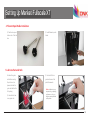
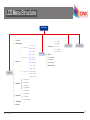
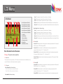
Fullscale XT
a Fast, High Resolution, Huge Printing Volume 3D Printer
User Manual
Contents
WELCOME
1
Interface
22
Safty
2
ParameterDefinition
23
Specifications
3
How it Works
4
FIRST RUN
29
Stick the Kapton tape
30
SETUP
5
Leveling Build Plate
33
Unpacking
6
Feed the Filament
35
Accessory
9
Print from SD Card
36
Tool Box
10
Unload the Filament
37
Setting Up Mankati Fullscale XT
11
Fullscale XT Outlook
15
MAINTENANCE
38
Maintenance
39
LCD INSTRUCTION
16
LCD Menu Structure
17
TROUBLESHOOTING
41
LCD Menu
18
Setting and Calibration Problems
42
Hardware Problems
43
SOFTWARE
20
Printing Problems
45
Download and Install
21
WELCOME
TO THE
MANKATI FULLSCALE XT
To get perfect prints, your may need to experiment and tinker at the beginning.
This User Manual will guide you to start your journey with the Mankati Fullscale XT
easily and quickly.
Forget your existing knowledge of other 3D printers, take the time to learn about
your Mankati Fullscale XT, it will show you a completely new experience.
Print your idea right from now on!
1
Safty
GROUND CONNECTION
CAUTION: Make sure the power grounded, if not, may cause the accumulation of static-electricity so as to damage electronic system.
HEAT and HIT
WARNING: Mankati Fullscale XT 3D Printer generates high temperatures and includes moving parts that can cause injury. Please Never Touch the nozzle,
the heated aluminum block or the build plate after preheating or printing to avoid scalding.
CAUTION: Do not leave the printer attended for a long time during printing. If you have to do so, do follow these guidances:
• Ensure that the first layer of the print is properly land on the build plate.
• Ensure filament wound on the spool to keep feeding smoothly, in case of tangles.
• Monitor your print periodically.
CAUTION: The melt filament will emit the plastic odor during printing. Please keep ventilation in the work place.
CAUTION: In case of emergency disconnect power supply from wall socket.
CAUTION: Refit and modification privately may destroy the working and safty performance. So any refits and modifications not expressly approved by
Mankati can void the right of warranty and safty gurantee.
COMPLIANCE: Your Mankati Fullscale XT has been tested strictly by SGS with the permission of FCC, CE, IC, C-Tick and ROHS.
It complies with the rules and limits of EMC, MD and ROHS, to provide reasonable protection against harm to the human, from electromagnetic
compatibility, mechanical structure and chemical component.
The users have the right to ask for the testing report with Mankati.
2
Specifications
Hardware
Fullscale XT
Forming Tech.
Fused deposition modeling (FDM)
Controller
Arduino ATmega2560 R3Micro Controller
Extruder Number
1 or 2 (Dual extruders Perfect supported)
Mother Board
Mankati Stable Main Board V3.x
250*250*300mm
Stepper Motor
X, Y axis 42*48, 1.3A; Z axis 42*63, 1.5A
Build Size
Geared Motor
E42*42, Ratio 1:10
Precision
X,Y 0.01mm, Z 0.015mm
Power Input
110~220V, 1.5A
Layer Resolution
0.04mm-0.4mm
Power Output
24V, 10.5A
Nozzle Diameter
0.4mm
Software
Max. Travel Speed
250mm/sec.
Operating System
XP, Vista, Win7, Win8, Mac, Linux/Unbutu
Max. Print Speed
180mm/sec.
File Format
STL, OBJ, GCode
Max. Extruder Temperature
270Deg.
Printing Software and Slicer
MankatiUM
Max. Hot Bed Temperature
110Deg.
Software Language
English, Deutsch, French, Nederlands, Spanish, Polish
Max. Extrude Speed
100mm/sec
Machinery
Specification
Filament
Filament Type
ABS, PLA(Spec.), PVA, PS, Nylon
Filament Diameter
3mm
Filament Temperature
150~270Deg.
Filament Colors
Black, White, Red, Yellow, Green, Blue, etc.
www.mankati.com
Dimensions
380*420*530mm
Weight
Around 34KG
3
How it Works
Mankati Fullscale XT 3D Printer makes solid, three-dimensional objects out of melted filament.
Your 3D designed files are translated into instructions for the Mankati Fullscale XT and read by the machine via SD card.
The Mankati Fullscale XT then heats the filament and squeezes it out through a nozzle onto a heated surface to build a solid object,
layer by layer. This method is called Fused Deposition Modeling [FDM].
Preparing the model
MankatiUM
Transfer the GCode file
Prepare the printer
Print it!
Use a 3D modeling software
to output stl or obj format 3D
modelfile.
MankatiUM is a software to
preparethegcodefileforyour
Fullscale XT.
SavetheGCodefileintotheSD
card, and insert it into the SD
card reader of the printer.
Before 3D printing, you need to
loadthefilamentfortheprinter.
Operate the knob beside the LCD
and choose the model from the
SD card inserted into the printer.
In MankatiUM, you can set
printing parameters for your
model, such as layer thickness,
printing speed and nozzle
temperature, then output a
gcodefileforprinting.
4
SETUP
Your Mankati 3D Printer was built and packaged very carefully at the Mankati
factory. Please take your time and carefully unpacking it and getting set up.
2
Unpacking
1. PlacetheMankatiFullscaleXTonthefloor.Leave
enough available space for unpacking
2. Your Mankati Fullscale XT is packed multiply by
carton, cardboard, foam and sealed bag to ensure the
machine to your hands in perfect status.
3. Removethefirstcardboardlayer.Opentheplastic
bag.
NOTE: You can download a PDF copy of this User
manual under manual at the support page: http://www.
mankati.com/download.html
6
Unpacking
4. Now it’s time to take out your Mankati Fullscale
XT from the box. Lift it out by grasping the frame
firmlybutgentlyattheleft ① and right ② of the
Mankati Fullscale XT.
5. Place it on a stable surface, and leave enough space
surrounding it to check accessories.
6. Removethestretchfilmaroundthe3Dprinter.You
canseealltheaccessories,toolsandfilaments.
Caution: Be careful NOT to grip the belt or shaft of
the motion system.
www.mankati.com
7
Unpacking
7. Take all the accessories out.
8. Takingoutthefilaments:
Fortheeaseoftransport,thefilamentsarefixedtightly
by build plate supporter. Let’s take them out, following
thenext3steps:
1) Connect power wire to printer.
2) Turn on the printer.
3)GototheLCDmenu:"Prepare>Autohome",and
the two holders will go to the top of Z axis.
4)TakeoutthetwospoolsofPLAfilamentandthetwo
feeding devices.
8
Accessory
3)1toolbox:includingthenecessarytoolsforinstallationandotheraccessories.
4)2feedingdevices:constitutedbygearmotorandfeederwiththeadvantagesof
high accuracy and easy to operate.
5)3enclosurecovers:installedon3sides(front,left,right)tokeepthetemperature
constant inside printing space.
Takingoutaccessories,toolboxandfilamentandcheckifbelowthingsareincluded:
1)2spoolsofPLAfilament,diameter3mm,1kg/spool;
2)1Buildplatform:ItispackedinthewhiteEPE.
www.mankati.com
9
Tool Box
5) 2*filament holders: Hold filament spool.
6) 5*big nuts: 4 for installation of build platform, 1 for backup.
7) 1* black plastic nut: Backup nut for leveling the heat bed.
8) 5* small nuts: 4 to install on feeding device, 1 for backup.
9) 1* fuse: Backup for power interface.
10) 1* power switch: Backup for broken power switch.
11) 1* button: Backup for broken button.
12) 1* Heating tube: Backup for broken heating tube.
13) 1* temperature controller: Backup for broken temperature controller.
14) 1* Bottle lubricant oil: XY axis and guide rails need to lubricate terminally.
15) 1* Kapton tape: Stick on the build plate to ensure the model fixing on the
build plate.
Checking if you find that anything described in the manual is missing, email us at
[email protected].
1) 1*USB cable: Connect computer and printer when printing or renewing
hardware.
2) 1*Power wire: Supply power.
3) 1*8GB Kinston storage card to store Gcode file for printing.
4) 2*printer handles: Install on machine and help to move machine easily.
16) 1* Scraper: To take out the model and clean the build plate.
17) 1* Screwdriver: Installation tool.
18) 1* Tweezer: Clean the platform after printing, or clean the nozzle and printer.
19) 2* Spanners: Installation tools
20) 1* Drill: Clean the nozzle.
21) 1* needle: Clean and unchoke the nozzle.
10
Setting Up Mankati Fullscale XT
1. Install the Holders
1). The four holes are
holders installation
position.
3). Use the screwdriver to
fixthetwoholdersonleft
and right of the printer
top side.
Note: Please confirm
you have tightened the
screw to avoid accident
of getting loose when
moving the printer.
2). You need a screwdriver,
four screws and two
holders.
www.mankati.com
4). Holders installation
done.
11
Setting Up Mankati Fullscale XT
2. Install the Build Platform
1) Turn on your Fullscale XT, enter “Prepare
>Moveaxis>Move1mm>MoveZ”,
loweringZaxisalittle(forexample30mm)
to avoid collision between nozzle and
build platform while installation.
3) Take out the nuts ⑥ and screwdriver
fromthetoolboxtofixtheplatformand
platformholderfirmly.
2) Insert the platform’s holder into the
middle of platform.
Note: After installing the platform
installation, please tighten the four black
screws a little bit more under the build
plate to lower it to avoid knocking the
extruders in next operation.
4) Connect the power wire and data cable
of platform with the connectors.
Caution: Make sure the connection fully.
Otherwise, it can cause the platform
heating problems or connectors overheated.
5) Done.
Note: The end of platform with black
connection wire should toward the
printer.
12
Setting Up Mankati Fullscale XT
3. Feeding Device Installation
1)Feedingmotor:
using small wrench
tofixNo.1feeding
motor on position 1.
3) Connect the data cable
with feeding devices.
2) Insert the end
of feeding tube
into the socket of
4) Feeding device
installation done.
feeding motor and
tightenfirmly.
www.mankati.com
13
Setting Up Mankati Fullscale XT
4. Filament Spool Holder Installation
1) Take the two spool
holders out of the tool
box.
2).Installfilamentspool’s
holder.
5. Lubricate the Guide Rails
We clean the guide
2). Lubricate the four
rails before sending
the printer out, so
please lubricate the
guide rails before the
firstprinting.
guide rails around the
printer framework.
1). Lubricate the two
cross guide rails.
Notice: Lubrication is very
important for good printing
performance, or else you
might encounter printhead
stuck problem.
14
Fullscale XT Outlook
1. SD-card slot
6. Print head
10. Power Socket
2. Push and rotate button
7. Filament guide tube
11. Name plate
3. Display
8. Printer holder
12. Spool holder
4. Build plate screws
9. Power switch
13. Material feeder
5. Build plate
www.mankati.com
14. USB Socket
15
LCD INSTRUCTION
In this chapter you will learn about detailed introductions of the LCD menus.
3
LCD Menu Structure
Info Screen
1.1 - Auto Home
2.1.1 - Nozzle
1.2 - Disable Steppers
2.1.2 - Nozzle 2
1.3.1.1 - Move X
1.3.1 - Move 10mm
1.3.1.2 - Move Y
1.3.2.1 - Move X
1.3.2.2 - Move Y
1.3.2 - Move 1mm
1.3 - Move Axis
2.1 - Temperature
2.1.3 - Bed
3 - Cool Down
4 - No SD Card
2.1.4 - Fan Speed
2 - Control
2.1.5 - Auto Temp
2.2 - Motion
1.3.2.3 - Move Z
2.3 - Restore Failsafe
1.3.2.4 - Extruder
2.4 - Save Memory
1.3.2.5 - Extruder 2
2.5 - Restore Factory
1.3.3.1 - Move X
2.6 - Firmware Version
1.3.3.2 - Move Y
1.3.3 - Move 0.1mm
1 - Prepare
1.3.3.3 - Move Z
1.3.3.4 - Extruder
1.3.3.5 - Extruder 2
1.4.1 - Preheat PLA 1
1.4 - Preheat PLA
1.4.2 - Preheat PLA 2
1.4.3 - Preheat ALL
1.4.4 - Preheat PLA Bed
1.5.1 - Preheat ABS 1
1.5 - Preheat ABS
1.5.2 - Preheat ABS 2
1.5.3 - Preheat ALL
1.5.4 - Preheat ABS Bed
1.6 - Leveling Bed
1.7 - Cool Down
www.mankati.com
17
LCD Menu
Info Screen
1
2
3
4
5
6
7
8
1. Actual Temperature of Nozzle 1;
2. Preset Temperature of Nozzle 1;
Move X: The extruder will move 10mm each step in X direction
Move Y: The extruder will move 10mm each step in Y direction
Move Z: The build plate will move 10mm each step in Y direction
Extruder: Thefeedingmotorofleftnozzlewillextrudethefilamentineachstepof1mm
Extruder2: Thefeedingmotorofrightnozzlewillextrudethefilamentineachstepof1mm
3. Actual Temperature of Nozzle 2;
4. Preset Temperature of Nozzle 2;
5. Actual Temperature of Build Plate;
6. Preset Temperature of Build Plate;
7. Cooling Fan;
8. Fan Speed Rate;
9. Filament Feed Rate;
10. Printing Process Bar;
11. Printing Time;
12. Build Plate Coordinate;
9
10
11 12
Press the knob to enter the menu:
1 - Prepare: The printer enters ready state
1.1 - Auto home
Theprinterreturnstooriginalstate(InX.Ydirection,theextruderreturnstheleftbottomintop
view;InZdirection,thebuildplatereturnstotopposition)
1.3 - Move axis:
Move 10mm: Move 10mm each step
Move X: Move 10mm each step in X direction
Move Y: Move 10mm each step in Y direction
Move 0.1mm: Move 0.1mm each step
Move X: The extruder will move 0.1mm each step in X direction
Move Y: The extruder will move 0.1mm each step in Y direction
Move Z: The build plate will move 0.1mm each step in Y direction
Extruder: Thefeedingmotorofleftnozzlewillextrudethefilamentineachstepof0.1mm
Extruder2: Thefeedingmotorofrightnozzlewillextrudethefilamentineachstepof0.1mm
1.4 - Preheat PLA:
Preheat PLA1: PreheatextruderandbuildplatetotheworkingtemperatureofPLArequired(
Default:Extruder,215℃ , Build plate, 45℃)
Preheat PLA2: Preheat extruder 2 and Build plate to the working temperature of PLA
required(Default:Extruder,215℃; Build plate, 45℃)
Preheat PLA All: Preheat two extruders both and build plate to the working temperature of
PLArequired(Default:Extruder,215℃; Build plate, 45℃)
Preheat PLA Bed: PreheatbuildplatetotheworkingtemperatureofPLArequired(Default:
Build plate, 45℃)
1.5 - Preheat ABS:
Preheat ABS1: PreheatextruderandbuildplatetotheworkingtemperatureofABSrequired(
Default:Extruder,255℃; build plate, 45℃)
Preheat ABS2: Preheat extruder 2 and build plate to the working temperature of ABS
required(Default:Extruder,255℃; Build plate, 45℃)
Preheat ABS All: Preheat two extruders both and build plate to the working temperature of
Move 1mm: Move 1mm each step
18
LCD Menu
ABSrequired(Default:Extruder,255℃; Build plate, 45℃)
Preheat ABS Bed: PreheatbuildplatetotheworkingtemperatureofABSrequired(
Default:Buildplate,45℃ ).
1.6 - Leveling Bed: Build plate calibration assist-function. Rotate the button, the extruder will
move to next position in clockwise direction in top view.
1.7 - Cool down: Cool down the extruder and build plate to normal temperature.
2 - Control: Adjust printer settings
2.1 - Temperature:
Nozzle: Left temperature setup
Nozzle 2: Right temperature setup
Bed: build plate setup
Fan speed: Cooling fan speed setup
Auto Temp: All the above data setup automatically
2.2 - Motion: Please do NOT change any data in this menu if without specialist experience.
Accel:Acceleratedspeedofextrudermotion
Vmax x: Max speed in X direction
Vmax y: Max speed in Y direction
Vmax z: Max speed in Z direction
Vmax e: Max speed of feeding motor
Vmin: Min printing speed
VTrav min: Min travel speed
Amax x: Max accelerated speed in X direction
Amax y: Max accelerated speed in Y direction
Amax z: Max accelerated speed in Z direction
Amax e: Max accelerated speed of feeding motor
www.mankati.com
A-retract: Accelerated speed of retract
Xsteps/mm: Transmission ratio of X motor
Ysteps/mm: Transmission ratio of Y motor
Zsteps/mm: Transmission ratio of Z motor
Esteps/mm: Transmission ratio of feeding motor
2.3 - Restore Failsafe: Please do NOT change any data setting here in this menu.
2.4 - Save memory: Record the coordinate of printing stop
2.5 - Restore factory: Restore the manufacturer default settings
2.6 - Firmware version:Currentfirmwareversion
Menus in Printing Process
During the printing, you can press the knob to change some printing settings.
1. Tune: Re-set some parameters
- F/R: the actual printing speed takes the percentage of the pre-set speed in the software. It can be
adjusted while printing according to the actual situation.
- Nozzle: Temperature setup of left nozzle
- Nozzle 2: Temperature setup of right nozzle
- Bed: Temperature setup of build plate
- Fan speed: Fan speed setup
- Flow: Filament feeding flow rate
- Flow 0: Filament feeding flow rate of left nozzle
- Flow 1: Filament feeding flow rate of right nozzle
- Auto Temp: Set all the above temperature automatically
- Change filament: To stop the printing and change the filament. It will record the printing stop position
so as to continue to print after filament changing.
2. Control: Please do NOT change any data in this menu if without specialist experience.
3. Pause: To stop the printing, but it will record the printing stop position to continue the printing.
4. Stop Print: To finish the printing job
19
SOFTWARE
This chapter will guide you how to download and install the software. And show you detailed
introduction of parameters in the software.
4
Download and Install
EnterMankatiofficialdownloadwebsite:
www.mankati.com/download.html
Choose the appropriate version of Mankati UM according
to your computer operation system. Our software apply
to Windows, MacOS, Ubuntu operating system.
Rightclickthesoftwareinstallationprogram,select"run
asadministrator"andinstallitfollowingtheprompts.
www.mankati.com
21
Interface
1
3
2
6. Rotate the model
8. Mirror image of the model
7. Change the size of the model
9. Other operation
5
4
6
7
8
1. Load 3D model, supporting the files of STL/OBJ/DAE/AMF.
Note: MankatiUM also can recognize planar images, and transfer
them to 3D model files. Supporting the files of JPG/BMP/PNG.
2. Save as Gcode file
3. If change any slicing setting, please click this "Slice" button to show
the real printing time and filament requirement.
4. Printing time, the length and weight of filament consume.
5. Simulate the printing process under different modes.
5.1 Normal: Default state
5.2 Overhang: Measure the angle of overhang, and judge if it is
necessary to generate the support structure
5.3 X-Ray: X-ray vision
5.4 Layers: Layer by layer to simulate the printing process
www.mankati.com
Five options for choice:
- Center on platform
- Delete object
- Multiply object
- Split object into parts (It will take
too much time, so it is better to do
this in modeling software)
- Delete all objects
22
Parameter Definition
Basic Setting
Quality
Speed and Temperature
Layer height: The lower layer height, the higher printing accuracy
within certain limits
Super accuracy printing: Recommended set as 0.1mm
High accuracy printing: Recommended set as 0.2mm
Giving consideration to both printing speed and accuracy printing:
recommended 0.25mm
High speed printing: Recommended 0.3mm
Printing Speed: Means the extruder’s moving speed. Printing speed
decides the quality of printing model quality. Mankati Fullscale XT’s
defaultspeedis30mm/s.Highspeedprintingcanbesetas5070mm/s.
Higher precision printing is available as 0.04mm, but because the
filamentextrudedat0.04mmistoosoftandthin,whichcannot
print complicated model. Meanwhile, the speed will get low too
much.
So here we don't recommend the printing less than 0.1mm unless
it is inevitable.
2nd extruder temperature: Viceextrudertemperature(default
as right extruder), setting according to the different melting
temperaturesofdifferentfilaments.
Flow: Flow compensation, the amount of material extruded is
multiplied by this value.
Default main extruder: Choose which one to be the main extruder.
Defaultasleftextruder.Afterfinishingamodelandyouwant
toprintanothermodelindifferentfilament(differentcolorsand
different materials). Changing vice extruder as main extruder can
solvefrequentchangingfilamentproblem.Thisfunctioncancome
effectiveonlywhenprintingsinglecolorfilament.
Bottom/Top thickness: Used as the model need capping. Common
setting as integral multiples of layer height, keep it near your wall
thickness to make an evenly strong part.
www.mankati.com
Printing Temperature: Mainextrudertemperature(defaultasleft
extruder), setting according to the different melting temperatures of
differentfilaments.
Shell thickness: Thickness of the outside shell in the horizontal
direction. Common setting as integral multiples of nozzle diameter
to represent the outer wall print laps.
Fill
Note: Function prompt will be shown when
you place the cursor on the tab.
Higher speed printing needs a balance by increasing nozzle
temperature,otherwisemayeasilycauseshortageoffilament’s
feeding. Printing speed also depends on the shape of model and
manyotherfactors.Recommendedspeedis≤70mm/s.≥70mm
may cause the step motor losing steps, which will reduce the model
printing accuracy.
Fill Density: Means the net support structure inside the model. The
higherfillpercentage,thehigherdensityofnetsupport.0means
non-fill,and100%meanssolidfill.
Bed temperature: Setting according to the different melting
temperaturesofdifferentfilaments.
Close bed after layer: Close bed temperature after certain layers.
Not only energy, but also can prolong the life of the hot bed. 0
disable this feature.
23
Parameter Definition
Support
Support type: For the model has parts hanging in the air, support
structure is a must when printing to ensure the parts hanging in the
air will not collapse.
Advanced Setting
Enable retraction: Enablefilamentretractionfunction
Retractthefilamentwhenthenozzleismovingoveranon-printed
area to avoid dropping and brushed. Details about the retraction can
beconfiguredintheadvancedtab.
-None: No support, if you print model with parts hanging in the
air but choose structure as none, the parts hanging in the air may
droop.
-Touching Build Plate: Most commonly used support type, means
the support will only been created when the support structure
touches the build plate.
-Everywhere: Create support wherever there is part hanging in the
air.
-Retraction speed: Speedatwhichthefilamentisretracted,a
higherretractionspeedworksbetter.Commonlyusedas80mm/
s.Averyhighretractionspeedcanleadtofilamentgrindingor
breaking.
-Distance: Amount of retraction. Set at 0 for no retraction at all. A
value of 5 seems to generate good result.
Note: Support structure may affect the smoothness of
model surface and printing speed.
If not essential, recommend to modify or split model to
reduce the use of support.
Dual Extrusion
Wipe &prime tower: The wipe-tower is a tower printed on every
layer when switching between nozzles.
Platform adhesion type: Different options that help in preventing
corners from lifting due to warping.
Tower volume per layer: Theamountofmaterialputinthewipe/
prime tower. This is done in volume because in general you want
to extruder a certain amount of volume to get the extruder going,
independent on the layer height. This means that with thinner layers,
your tower gets bigger.
- None: Default form of using outsider lining.
- Brim: Addsasinglelayerthickflatareaaroundyourobjectwhich
is easy to cut off afterwards, and the recommended option.
- Raft: Adds a thick raster at below the object and a thin interface
between this and your object.
Ooze shield: The ooze shield is a line thick shell around the object
which stands a few mm from the the object and catches any oozing
from the unused nozzle in dual-extrusion.
Note: Enabling the brim or raft disables the skirt.
Dual extrusion overlap: Add a certain amount of overlapping
extrusion on dual-extrusion prints. This makes the different colors
filamentjointedbetter.Default0.1
Support dual extrusion: Which extruder to use for support material.
For easy break-away support you can use either extruder.
Youcanchoosemainextruder(leftextruder)toprintmainstructure,
2ndextruder(rightextruder)toprintsolublesupportmaterial.
Retraction
Note: Function prompt will be shown when
you place the cursor on the tab.
24
Parameter Definition
Quality
Initial layer thickness: Layer thickness of the bottom layer. A
thicker bottom layer makes sticking to the bed easier. Set 100
means setting the bottom thickness the same as other layers.
Initial layer flow: The extrusion capacity when printing the
bottom layer.
Cut off object bottom: Sinks the object into platform, this can be
usedforobjectsthatdonothaveaflatbottomorcuttingoffthe
alreadyfinishedmodelheightinordertostickormontagewith
other parts easily.
Inner shell speed: Speed at which inner shells are printed. If set
to 0 then the print speed is used. Printing the inner shell faster
than the outer shell will reduce printing time. It is good to set
thissomewhereinbetweentheoutershellspeedandtheinfill
printing speed.
Infill speed: Speedatwhichinfillpartsareprinted.Ifsetto0
thentheprintspeedisusedfortheinfill.Printingtheinfillfaster
can greatly reduce printing time, but this can negatively effect
printing
Continue print from cut off: Continue print from cut off. The
printwillfirstraisethenozzletotheheight,thencontinueprint
the object left last time.
Note: when select this function, should disable brim,
raft and skirt features at the same time.
Speed and Temperature
Travel Speed: Moving speed without printing.
Usually setting at 80 is the best choice, also can reach speeds
of150mm/satmost.Butitmaycausethemotorstopmissing
problem.
Bottom layer speed: The bottom print speed. Recommended
20, set as 0 means the same as other layer. Reducing the bottom
layer speed can help model stick more closely to platform.
Outer shell speed: Speed at which outer shell is printed. If set to
0 then the print speed is used. Printing the outer shell at a lower
speedimprovesthefinalskinquality.However,havingalarge
difference between the inner shell speed and the outer shell
speed will effect quality in a negative way.
www.mankati.com
25
Parameter Definition
Expert Setting
Nozzle
Nozzle size: Nozzle diameter.
Mankati Fullscale XT’s default nozzle diameter is 0.4mm.
So in Mankati UM the nozzle size’s default is 0.4. If you
choose 0.3mm, 0.5mm or 0.8mm diameter nozzle,
pleasefillthecorrespondingrightfeature.
NozzlesizehasalittleinfluenceofaccuracyonZaxis
direction.Butifprintingfinestructuremodel,smaller
diameter can help to get better result.
The relationship of size of the nozzle and print speed
are square times, so increasing the nozzle will greatly
improve print speed.
Filament
Filament Diameter: Printfilamentdiameter.Pleaseuse
the exact feature as exactly as possible, too big or too
smallwillinfluencetheextrusion.
Filament Diameter 2: The2ndextruderfilament
diameter. If the same as the main extruder, please set as
0.
Retraction (nochangeatbest)
Minimum travel: Minimum amount of travel needed for
a retraction to happen at all. To make sure you do not
get a lot of retraction in a small area. R ecommended
2 as best performance, too small will lead to frequent
retraction.
Enable combing: Combing is the act of avoiding
holesintheprintfromtheheadtotravelover.Enable
combing extruder will always touch the surface of
model but disable retraction. If combing is disabled
the printer head moves straight from the start point to
the end point and it will always retract. Default enable
coming, but it will increase printing time.
Minimal extrusion before retracting: The minimal
extrusion that needs to be done before retracting again.
If a retraction needs to happen before this minimal is
reached the retraction is ignored. This avoids retraction
alotonthesamepieceoffilamentwhichflattensthe
filamentandcausesgrindingissues.Recommended
0.02 at best performance, 0 means unlimited retraction
frequency.
Dual Extrusion
Dual extrusion switch amount: Amount of retraction
when switching nozzle with dual-extrusion. After
switching,thefilamentinthenoworkingnozzleneed
to be retracted with some amount to avoid oozing. Set
as 0 for no retraction at all. Recommended setting as
25 for best performance.
Cool
Enable cooling fan: Enablecoolingfanduringprinting
tohelpcoolfilamentdown.
Minimal layer time: The minimal time of printing layer
to ensure enough cooling time before printing next
layer. Print speed will adjust automatic to satisfy this
feature.
Fan full on at height: The height at which the fan is
turned on completely. For the layers below this the fan
speed is scaled linear with the fan off at layer 0.
Fan speed min: Minimal fan speed when normal
printing
26
Parameter Definition
Fan speed max: Maximal fan speed when automatic slowing
down printing.
Minimum speed: Minimum printing speed of each layer.
Recommended setting as 10 with best performance. Too slow
will result in nozzle oozing.
Cool head lift: Lift the head, if the minimal layer time is not
enough, to extend the cooling time for model cooling.
Spiralize
Infill
model sticking to platform.
Solid infill top: Create a solid top surface, if set to false the top
isfilledwiththefillpercentage.Disablethisfeatureandsetfill
densityas0toprintcups/vasesthatarewithouttopmodel.
Raft
Solid infill bottom: Create a solid bottom surface, if set to false
thebottomisfilledwiththefillpercentage.Disablethisfeature
andsetfilldensityas0toprintbuildingsthatarewithout
bottom model.
Spiralize the outer contour: Spiralize is smoothing out the Z
move of the outer edge. This will create a steady Z increase over
the whole print. This feature turns a solid object into a single
walled print with a solid bottom.
Infill overlap: Amountofoverlapbetweentheinfillandthe
walls.Thereisaslightoverlapwiththewallsandtheinfillsothe
wallsconnectfirmlytotheinfill.Recommendedsettingas10
withbestperformance.Toobigwillinfluencequalityofmodel
surface.
When enabling this feature, the top will not be printed and
automaticallysettinginfillas0.
Support
Skirt
Line count: Theskirtisalinedrawnaroundtheobjectatthefirst
layer. This helps to prime your extruder, and to see if the object
fitsonyourplatform.Recommendedsettingas1withbest
performance. Setting this to 0 will disable the skirt. Multiple skirt
lines can help priming your extruder better for smaller objects.
Start distance: The distance between skirt line and model.
Default distance is 3
Minimal length: The minimal length of the skirt, if this minimal
length is not reached it will add more skirt lines to reach
this minimal length. Recommended setting as 250 with best
performance. If the line count is set to 0 this is ignored. If the
model is too small to have a too short skirt line will not help to
clean nozzle.
Fill amount: Support print density.
Recommended setting as 15 with best performance. More
density makes the support not easy to remove. Less density
influencesprintquality.
Distance X/Y: Distance of the support material from the print,
intheX/Ydirections.0.7mmgivesanicedistancefromthe
print so the support does not stick to the print. Too far will
influencesupportperformance.
Distance Z: Distancefromthetop/bottomofthesupport
to the print. A small gap here makes it easier to remove the
support but makes the print a bit uglier. 0.15mm gives a
goodseparationofthesupportmaterial.Toofarwillinfluence
support performance.
Birm
Extra margin: If the raft is enabled, this is the extra raft area
around the object which is also rafted.
Line spacing: When you are using the raft, this is the distance
between the centerlines of the raft line.
Fix Horrible
Combing ererything ( Type-A )/( Type-B ):
This expert option adds all parts of the model together. The
result is usually that internal cavities disappear. Depending on
themodelthiscanbeintendedornot.Enablingthisoptionis
at your own risk. Type-A is depended on the model normals
and tries to keep some interal holes intace. Type-B ignores all
internal holes and only keeps the outside shper per layer.
Keep open faces:
This expert option keeps all the open bits of the model intact.
Normally Mankati Tries to stitch up small holes and remove
everything with big holes, but this option keeps bits that are
not properly part of anything and just goes with whatever it is
enable you to slice models otherwise failing to produce proper
paths.Aswithall"Fixhorrible"options,resultsmayvaryand
use at your own risk.
Extensive stitching:
Extrensivesitichingtriestofixupopenholesinthemodelby
closing the hole with touching polygons. This algorthm is quite
expensive and cloud introduce a lot of processing time. As with
all"Fixhorrible"options,resultsmayvaryanduseatyourown
risk.
Birm line amount: Defaultas5,morelines,morefirmlythe
www.mankati.com
27
Parameter Definition
Plugins
We supply 3 plugins for you. These 3 plugins will help to give
stronger control feature. You can set different parameter with
different print heights to have more accurate model.
Double-click certain plugin name to start using. After starting
using you can set parameter in below setting interface.
If you want to cancel this plugin, click”X”on the right top of
parameter setting interface.
Change Filament At Z: Youcanchangethefilamentinthe
printing process at a certain height of the print.
Pause at height: You can pause printing at a certain height of
the print, and you can percisely locate the print head position.
Tweak At Z: You can reset the printing parameters at a certain
height of the print, this is a powerful option for experts.
Youcanresetprintingspeed,flow,bedtemperature,nozzle
temperature and fan speed.
28
FIRST RUN
ThischapterguidesyouthroughthestepsandthefirstrunoftheMankatiFullscaleXT.
5
Stick the Kapton tape
Stickthekaptontape(15)to
the build plate.
It is the high temperature
resistance doubleside tape,
it contains three layers.
2. Uncover one side of the
tape, and then try to stick it
on the plate. Please ensure
the tape is smooth enough
without any bubbles.
1. Clean the plate carefully
3. You can use the yellow
to ensure the clean and
tidy, it will help you aviod
bubbles after applying the
tape on it.
board in tool box to push
and press it while sticking.
Takethetapeout(15).
If covering the plate
completely, it will need 3
lines of the tape.
30
Stick the Kapton tape
4. Cut the tape off at the
same width of the plate.
6. Cut off the parts on the
screws when sticking the
third line.
6.1
5. Stick the second line in
the same way.
6.2
www.mankati.com
31
Stick the Kapton tape
7. When appear some
big bubbles, just use
needle(21) stick into
them. Then smooth
them with yellow
board.
8. After sticking the tape
on the plate, please
uncover the other side
of the tape.
Note: After several
printing, the
stickiness is not
strong enough,
please change the
tape.
8.1
8.2
32
Leveling Build Plate
Notice:
Plate Leveling Guide
• Tightening the black screw (turning them to the right) to reduce
plate height.
• Loosening the black screw (turning them to the left) to increase
platform height.
• The gap between the nozzle and the build plate should be
about 75% of the layer thickness you set in the software.
Why Leveling Build Plate is
Important?
Frequent build plate leveling can keep Mankati
Fullscale XT best performance. Re-leveling cannot hurt
the printer but without leveling will decrease your
success rate of printing.
1. Tightening the four black screws as tight
as it can to reduce the build plate height to
avoid collision between nozzle and plate.
• If the build plate is too far from the extruder nozzle,
or if one part of the build plate is farther from the
nozzle than another part, your object might not stick
to the build plate.
• If the build plate is too close to the extruder nozzle,
the build plate will block the extruding of filament
from the nozzle. The nozzle will scratch the build plate
.
• Frequent build plate leveling will help to ensure that
objects always stick well to the hot bed.
www.mankati.com
2. Lifting the build plate to the top of the
Z-axis.Gotomenu"Prepare"-choose
"Autohome"intheLCD,theextruder/print
head will go to the original point, the build
plate will go up to the top of Z-axis.
33
Leveling Build Plate
3. Now, begin to adjust the four corners.
Use a name card between the extruder and the hot bed,
move it back and forth. You should feel some friction on
the card but still be able to easily pass the card between the
plate and the extruder nozzles without tearing or damaging
the card.
4. Adjust next three corners in anti-clockwise direction by
same method.
5. Do adjust all four corners repeatedly at least 3-4 times to
ensure the best gap you get.
If the friction is too big, it means the gap between nozzle
and plate is too small, you need to reduce plate height by
loosening the screw.
On the contrary, if almost no friction, it means the gap is
too big, you need to increase plate height by tightening the
screw.
34
Feed the Filament
1. Preheatthenozzle:
Choose”Prepare”>”preheat
PLA(orABS)”onLCD.
Choose the nozzle you want
to preheat.
3. Continue to feed the
filamentinuntilitemerges
from the nozzle.
Note: Please DO push the filament
GENTLY.
If filament attaches the nozzle, just
keep them attached, stop pushing
hardly. Otherwise, the nozzle
connection could be broken.
After the nozzle is preheated
enough, the filament will flow out
from nozzle naturally.
2. Feed the end of the
spooledfilamentintothe
filamentguidetube,whereit
attaches to the extruder.
4. Tighten the black screw
tofixthefilamentwiththe
clamp, not too loose or too
tight.
Caution:
1. Ensure the clamp is not too tight or too loose, otherwise, filament feeding will have problem causing failure prints.
2. After feeding successfully, check if filament has twining and knotting to ensure filament feeding smoothly.
3. Lubricate the XY axis and sliding blocks to avoid motion stuck.
www.mankati.com
35
Print from SD Card
1. Input the 3D modeling
filesinourslicingsoftware
(MankatiUM),andoutput
theGcodefilesintheSD
card.
3. Choose “Print from
SDcard”,selecttheright
Gcode.
Note: It is better to use the
default settings for the first
run.
2. Insert the SD card into
Mankati Fullscale XT.
4. When your 3D print
finished,thebuildplatewill
move down and be heated
to 50℃ automatically so
as to take out the model
more easily.
Use a shovel to take it out
gently to avoid the damage
of the model.
Note: If the model is difficult to be removed, you can raise the build plate temperature to 60.
Warning: Do not touch the nozzle until it is cooled down totally (The temperature on LCD must be
lower than 30 degrees)
36
Unload the Filament
1. Heat the nozzle to the working temperature of
filament.Forexample,PLA215℃ and ABS 235℃ .
2. Pullthefilamentoutindirectionofperpendicular
to the feeder motor hardly and quickly.
Note:
1. If the filament is stuck, please find solution in
troubleshooting chapter.
2. If the printer stops working for a long time,
please switch off the printer to avoid the filament
carbonized, which will cause the nozzle clogged.
Clean the dust on the build plate. It can extend the
lifetime of the kapton tape.
www.mankati.com
37
MAINTENANCE
To keep your Mankati Fullscale XT in perfect performance, some basic periodical maintenance is a must.
This chapter shows you some practical tips which will help you to take care of your printer well.
6
Maintenance
Build Plate
Ensure that the plate is clean. Bubbles, scratches, dust, and oil from your hands are avoided.
1.Usetweezertoremovefilamentresidue.
2. Do not touch the platform glass with sharp things.
3. If do not use the printer for a long time, please clean up the tape, clean the glass and fully release the four black screws under the build plate.
Cleaning the filament feeder
After a lot of printing, the wheel in the filament feeder might accumulate small plastic particles.
You can clean this with a simple brush.
1. Remove the black screw on the feeder motor totally.
www.mankati.com
2. Select“Prepare”>“moveaxis”>“move1mm”>“move
extuder”.Thefeedergearwillstarttowork.
3. Clean small plastic particles with a simple brush.
39
Maintenance
Lubricating the guide rails
1. Clean the X-Y axis and guides rails.
2. LubricatetheX-Yaxisandrailguidesperiodically,nooverflowisappropriate.
40
TROUBLESHOOTING
In case something goes wrong with your Mankati Fullscale XT, the following chapter will help you. From
diagnosingandfixingtheproblemyourselftocontactingsupport.
7
Setting and Calibration Problems
Q: Temperature parameters setting of several commonly used filaments
Q: There is the crack on the model, or the joint problem among the layers.
A: PLA: Nozzle temperature: 200-215℃ Bed temperature:45℃
A: 1.Build plate is not properly leveled. Please level build plate once again.
ABS: Nozzle temperature: 245-255℃ Bed temperature: 80-95℃
2. Material is not adhering to the build plate. Please stick the kapton tap to your build plate.
PVA: Nozzle temperature: 190-220℃ Bed temperature:45℃
Q: Only one fan is working when Mankati Fullscale XT in standby model.
Q: What are the relationships among the layer thickness, print speed and nozzle temperature?
A: The purpose of parameters interaction is: to leave enough time for the filament heating and cooling.
Normally, if the layer thickness goes up, please reduce the printing speed and turn up the printing
A: This is not a breakdown. There is one fan is the normal working fan(normally the right side one),
the other one is system controlled fan. Normal situation is that the right fan starts to work, but the
left fan will start to work after finishing the first layer printing.
temperature properly (If the printing speed is over 60, turn up by 5℃ ; if over 90, turn up by 10℃ );
Conversely, if the layer thickness goes down, please increase the printing speed and turn down the
printing temperature.
Q: While printing the model with sealed roof and bottom, how to set excellent parameters to get high
quality printing surfaces of the roof and bottom?
A: Increase the printing thickness of the top or bottom in the basic parameters.
Q: The idle nozzle scratches the printing model while single color printing,
A: 1. The height of the idle nozzle is too low, turn it up.
Please move the build platform to the top of Z-axis, adjust the height of two nozzles according to
the gap between the print head and the platform, tighten the idle nozzle by wrench and make it a
little bit higher than the other one.
2. The printing flow is too high, causing the actual layer thickness is higher than the original setting,
Q: When printing the model with single layer thickness, how to set parameters?
A:
Usually please keep the layer thickness of the model over 1mm; Meanwhile, choose the “Spiralize”
after a while, the object is over high and touch the main nozzle.
Please turn down the printing flow.
function in “Expert”setting.
Notes:
1. Layer thickness setting in the software can’t be over 0.8 times of the nozzle diameter (For example,
when the nozzle diameter is 0.4mm, the layer thickness setting can’t be over 0.32mm).
2. The maximum temperature of the nozzle is 270℃ , and the build plate is 110℃ . The parameters of
materials from different manufacturers could be different, so it is better to consult the relevant material
manufacturers about the temperature setting.
42
Hardware Problems
Feeder and Extruder Problems
Q: Nozzle clogged
A: 1. There is the impurity in the filament, which is stacked in the nozzle.
Please clean the nozzle by the needle; or take the nozzle off and clean inside of the nozzle by
needle and drill.
Please reduce the nozzle preset temperature.
2. Temperature controller damage.
Please replace the temperature controller.
3. LCD cable loose / LCD damaged.
2. The nozzle is overheated causing the filament carbonized inside.
Please clean the nozzle by needle; or take the nozzle off and clean inside of the nozzle by needle
and drill.
3. The deformation of the nozzle hole occurred by external force.
Please replace the nozzle.
Q: The nozzle heating failed
A: 1.The heating tube connection is too loose.
Please tighten the connection.
2. Heating tube/ temperature controller/ power tube damage
Please check if one of the nozzles works well, but the other one cannot be heated, please
troubleshoot by the following methods:
1) Open the machine case, and find out the connectors of two heating tubes, exchange the two
connectors, heat the nozzle again. If the failed one can work now, it means one heating tube is
broken and needs to be replaced;
2) If after exchanging the two heating tube, the failed nozzle still can’t work, please exchange the
heating tubes back, and try to exchange the connection of the two temperature controller, heat the
nozzle again, if the failed nozzle can work, it means one temperature controller is broken and needs
to be replaced;
3)If the above cannot solve the problem, it means it should be the problem of the power tube on
the main board, please replace it.
Q: Print Head Stuck/Cannot move
A: 1. The axes lack of lubricating oil.
Please clean the axes and smear the lubricating oil evenly.
2. The deformation of machine framework caused by external force during the transportation.
3. The cable connection of X.Y motor is loose.
Please open the machine base, check and re-connect the cable.
4. The fixing screw of the timing pulley is loose.
Please check the fixing screw of XY axis, find out the loose one, and tighten it with crewdriver.
5. Synchronous belt drops or breaks.
Please change a new synchronous belt.
Q: Print head hit the framework
A: The connecting wires of limit switch get loose or the limit switch is broken.
Please check if the wires on the hit side, if the wires connecting limit switch and main board
are loose. If yes, you need to pull out the wires and reinsert. If no, that means the limit switch is
broken and need to be replaced.
Q: Filament Feeder Motor make intermittent noise
A: 1. The clamp of the feeding device is too tight..
Q: MAXTEMP/ MINTEMP
A: 1. Nozzle temperature is too high.
www.mankati.com
Loosen the screw of the clamp..
2. Nozzle clogging, causing the filament not to be fed smoothly.
Please clean the nozzle with drill and needle..
43
Hardware Problems
Build Plate Problems
Q: Even the screws under build plate have been loose totally, the build plate still is far away from the
nozzle (the gap between build plate and nozzle is too big to be adjusted).
A: A: Adjust Z axis limit switch on the back the printer, raise it a little bit; after adjusting, if problem
still exist, the main cause is deformation is not enough of the hot bed’s corners, it can be removed
by tensile processing.
Q: The Z-axis movement of the build plate is abnormal.
A: 1. The top of the Z-axis screw is loose.
Please reinforced screw at the top of the Z-axis screw.
2. Z-axis motor loose connections.
Please open the base to re-plug the motor cables.
3. Z-axis screw need lubrication.
Please add oil to the Z-axis screw.
44
Printing Problems
Q: Problem with first layer printing
Q: The filament doesn't stick onto the build plate.
- A1: The gap between nozzle and build plate is too big.
- A2:The build plate has not been leveled yet.
- A3: Kapton tape has not been sticked on the build plate yet;
or the non-sticky top layer of the Kapton tape is not removed.
- A4: The first layer’s height is too small, recommended setting as ≥0.2
tape; Slow down the printing speed of first layer; Use the enclosure plate to keep
the constant temperature while printing; Avoid air condition’s blowing directly; Inside
ventilation should not be so strong.
Q: Model surface is loose with crack
Q: Litte filament stick onto the build plate.
A: The gap between nozzle and build plate too small which may cause the nozzle
clogged.
Q: No filament output from the nozzle.
A: The filament has not entered into the end of the nozzle yet when you feed the
filament.
Q: The edge is lifted, or the print cracked while printing with ABS filament
Please keep the build plate heated continuously; Change a new Kapton
A: The layer thickness is too big; Or printing speed is too high( the nozzle temperature needs
to do responded balance to have a faster printing speed); Or the temperature is too low; Or
the wall thickness is too think; Or 3D model is not completely closed solid; Or the feeding
device’s fixing screw is too loose; Or wrong choice of filament diameter; Or filament quality
is poor; Or the filament gets stuck and could not be fed smoothly.
Q: Model has flow line
www.mankati.com
45
Printing Problems
A: Temperature is too high; Or the filament is carbonized or liquefied(PLA will get
liquefied if over-high temperature, ABS will get carbonized if over-high temperature)
If still cannot solve the problem, please contact with our technical support team at
[email protected]
Q: Model surface is unsmooth
Q: Hard to remove the support structure
A: Turn the direction of model properly in MankatiUM; The support density should not be
set too high; Divide the model into different parts to print if necessary.
Q: Failed prototyping of small model
A: If printing a small model, the extruder will always move in a small space, so the heat will
be concentrated in the model, and hard to be distributed.
That's why it is hard to print the very small model.
The solution is to print 3-4 pieces of the small model together. If so, the extruder will
move among different models, leaving time for heat dissipation.
Q: Mankati Fullscale XT stops suddenly sometimes
A: 1. Gcode file saved incompletely.
2. USB connection cable has problem while choosing online printing or computer is in
standby model.
3. Something wrong with the power outlet.
4. If printer cannot be turned on after stopping, it means that the fuse on the power outlet
should be blown out.
A: Reduce the retraction travel; Or reduce minimal extrusion before retracting;
Q: Some part of the object unable to be modeling.
Note: Please reduce the retraction amount if retracting frequently.
Q: Model is easy to fall off
A: Having not used the Kapton tape or the Kapton tape loses stickiness; Or the model
bottom is too small, you can use a hot melting glue gun to help; Adding support
structure to support model; Using the feature in MankatiUM of Advance-Quality-Cut
off object bottom.
Q: There is the joint dislocation between the parts while dual color printing.
A: Adjusting the feature of the relative position coordinate in MankatiUM: "MachineMachine settings-Extruder 2".
A: Try the support functions in the MankatiUM software.
46
For Sales, Service and Support Call DNK Systems on 1300 309 529