1
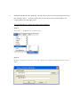
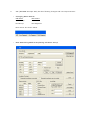
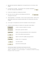
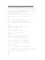
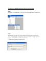
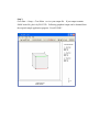
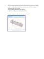
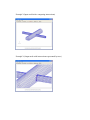
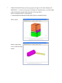
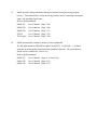
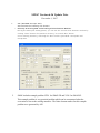
SMAP Version 6.56 Update Note
December 1, 2007
1.
AIG (AD DRG N-2D Input GU I):
AIG includes the following new feature:
C
Dire ctly Ex ecu ting AIG and P lottin g F inite Elem en t M esh es.
During the AIG input editing phase, you can see the current finite element meshes by
clicking “Save” button first and then clicking “ F.E. Mesh Plot” button.
In the working directory, following two files are also generated: Group.Mes and
Group.Man.
2.
SMAP includes example problem VP24 for SMAP-2D and VP16 for SMAP-S2 .
This example problem is very practical problem which can be encountered when the
excavation is near to the existing structures. The finite element meshes for this example
problem were generated by AIG.
SMAP Version 6.55 Update Note
March 1, 2007
1.
AIG (AD DRG N-2D Input GU I):
AIG includes the following new feature:
C
Se gm en t Ed itor.
Seg m ent Editor is a b uilt- in text ed itor w hich can be u sed to ad d, de lete, or m odify
the segm ent data for the existing g roups.
2.
PLOT-3 D (SM AP Post-processing Program ):
PLOT-3 D includ es the following n ew features:
C
Specifying Ma terial Colors
Material colors for Continuum/Beam/Truss can be specified
(Vie w -> M esh -> Color)
C
S av in g Ne w Vie w s a nd P lo tt ing Exis ting View s
Now, y ou c an save the curren t view s by clicking save button .
Existing views can be replotted by selecting
Plot-> Existing View -> View No
3.
SMAP supports Additional Gravity Loads with intensity time history so that
change of water table and pseudo-dynamic earthquake loads can be modeled.
Refer to updated manuals and example problems.
SMAP-S2:
User’s Manual (Pages 4-45, 4-45a)
Example VP15
SMAP-2D:
User’s Manual (Pages 4-84, 4-84a)
Example VP23
SMAP-3D:
User’s Manual (Pages 4-70, 4-70a)
Example VP23
SMAP Version 6.54 Update Note
December 1, 2006
1.
GEN-3D (SMAP-3D Pre-processing Program):
If NEW NO = -1 in C ard 3.6, it a ssum es th at new m ateria l prop erty n um ber 1
consists of joint elements whose joint face designation number, KS=6.
This feature is demonstrated in the GEN-3D Example 8.
2.
PLOT-3 D (SM AP Post-processing Program ):
PLOT-3 D includ es the following n ew features an d bug corrections:
C
Specifying Element Number Range on Clip Plane
Num bers for element and m aterial can be plotted within a specified element num ber
range on clip plane (View -> General -> Elem ent Num ber Range)
C
Plotting Beam Stresses and Strains for SMAP-S2 / SMAP2D
Following beam stresses and strains can be plotted for SMAP-S2 / SMAP-2D
- Inner ex trem e fiber stress / strain
- Outer extrem e fiber stress / strain
- Inner reinforcing bar stress
- Outer reinforcing bar stress
C
Correcting Bugs
Following problems are corrected:
Failure of show ing m aterial colors on and arou nd clip plan e whe n “Visible Su rface
with Material Color” (in Plot -> Mesh -> Mesh Typ e) is selected to plot meshes
around clip plane.
Failure of show ing visible surfaces w hen on ly “Joint” is selected in View -> M esh ->
Element Type.
3.
SM AP-S2 /2D /3D inclu des prog ram “Sh rink File” to rem ove extra blank s paces b efore
the carria ge return .
This will redu ce th e size of the file w here blank s paces a re
existing before the carriage return.
To ru n Sh rin k File , fo llo w the s teps lis ted belo w :
Step 1.
Go to Run -> S upplem ent -> Shrink File
Step 2.
Browse or type your input file. You can change your default output file name as you
wa nt.
4.
SM AP-S2 /2D A DD RGN -2D asso ciated with A IG (SM AP Pre-processing Program ):
ADD RGN -2D inclu des the following new featu res and bu g corrections:
C
Recalculating Segment End Coordinates by Arc Se gm ent D ata
W hen a gro up in A IG consis ts of arc segm ents, seg m ent end coord ina tes are
recalculated internally based on arc segment data.
Therefore, when a line segment
is conn ected to an arc se gm ent, the coordin ate w hich is com m on to b oth seg m ents is
gov erne d by end poin t of arc se gm ent.
C
Correcting Bugs
Following problems are corrected:
Failure of writing the beginning and ending angles of arc segment for the values that
are less th an or eq ual to -1 00 (C ard 3.3 .5.4.3.1 in AD DR GN -2D Users M anu al).
This
error was due to the use of insufficient format in writing angles (old format: F7.3,
corrected new form at: F7.2).
5.
AIG (AD DRG N-2D Input GU I) has the following chang es and n ew im provem ents:
C
Ch an gin g M en u N am es.
O ld Na m e
N ew Na m e
Start Group
AIG
End Group
End Segment
New menus are shown below.
C
Ne w AIG Dia log W ind ow Re plac ing Old Sta rt G rou p.
1)
Inp ut d ata associate d w ith FEM AP Plot is n ot su pp orte d as it is not show n in AIG
window.
2)
Line options are included.
Group outlines can be plotted with different
line color, line type, and line thickn ess.
3)
Groups can be hidden by checking the check box
4)
New m esh can be overlaid over the existing group mesh by
che ckin g th e check b ox.
5)
Assigning MATNO = 0 for MTYPE = 3 can be used to specify element activity in the
region without altering the material property data in the region where the group
occupies.
6)
Local origin can be specified fo move the coordinates of the current group.
7)
Following command buttons are added on the right side of AIG window.
Create or modify the segment of a group.
Show group / segm ent num bers.
Update current group parameters shown in AIG window.
Save all the u pdate grou p param eters.
Replot to show all the upda te group geo me tries.
Delete, m ove, or copy groups.
Close AIG window.
Finish and exit AIG program.
C
Generating Straight Line Element with En d P oin ts O nly
“Straight Line Element with End Points Only” can be generated by specifying
“NDIV = 1 with IEND = 0" for the line segment.
free part of earth / rock anchor
This feature is useful for modeling
C
Supporting Drag and Drop in Plotting Text
Texts can be added on the screen using “drag and drop” method in Draw -> Text
menu.
In order to save such text data in AIG plotting, following two files in the sub
working directory “Temp” should be saved in some other folder: MESHFILE.MES and
PLTDSO.DAT
To reproduce the text data in AIG plotting, copy those two files in the
new sub working directory “Temp” and then select plotting program PLOT_2D in
Plot -> Plot Options menu.
SMAP Version 6.53 Update Note
September 1, 2006
1.
SMAP-S2/2D/3D allows users to run their own Fortran application programs (up to
maximum of 5 programs) through SMAP menu procedure.
Main advantages of running application programs through SMAP menu are:
C
Easy Access of Input File
Input file can be easily accessed through browser without writing file open window interface.
C
Automatic Naming of Output File
Output file can be automatically named with the file extension of “Out” by default.
C
Displaying Error Messages
User controlled error messages can be displayed on the screen simply by writing those
messages on the file.
C
Plotting SMAP Mesh Output File
When the execution of your application program is finished, PLOT-3D is automatically opened
whether or not your output contains SMAP mesh file.
If your output is written in the format of
SMAP mesh file, you can view that by PLOT-3D.
C
Using Sample Source Programs and Batch Procedure File
Sample source application programs are given along with batch procedure file to compile the
source for the dynamic link library.
You can write your own application programs by
modifying these sample programs and then compile them simply by running the given batch
procedure file.
C
Using Subroutines Written for SMAP Mesh File Format
Subroutines for SMAP mesh file format are provided in the sample source programs.
When the application program is to generate the SMAP mesh file, simply call these subroutines
to write in SMAP format.
To write your own application program, follow the steps listed below:
Step 1.
Install Microsoft Power Station 4.0 in the directory C:\MSDEV
Step 2.
Modify the sample application source program “UserAP1.FOR” in the directory
C:\Smap\Smap3d\Program\User\UserAP-1 as you want. Partial listing of the sample
application is shown on the next page.
Step 3.
Run the batch procedure file “MakeAP1.BAT” simply by typing or double clicking the
file name.
Step 4.
Copy the “UserAP1.DLL” to the directory C:\Smap\Smap3d\Program
Partial Listing of Sample Application Program: UserAP1.For
C
UserAP1 is for User Application Program 1
C
Users need to write their own program "UserAP1.FOR" by modifying
C
the one in C:\Smap\Smap3d\Program\User\UserAP-1 and then compile
C
it by running the Batch File "MakeAP1.BAT".
C
Note that Fortran Power Station 4.0 should be in your computer.
C
Once you obtained "UserAP1.DLL",
C
save "UserAP1.DLL" in the directory C:\Smap\Smap3d\Program.
C
SUBROUTINE UserAP1 (UI, UO, IFILEO, UR, IERROR)
C
C
Input
C
UI
: Tape Unit No for Input
C
UO
: Tape Unit No for Output File (set as UO = 6)
C
IFILEO : Output File Name including Proper Path
C
UR
File (set as UI = 5)
: Tape Unit No for Error Message File (set ad UR = 900)
C
C
Output
C
Execute UserAP1 and save on the file IFILEO
C
IERROR = 0 : Exit Without Error
C
= 1 : Exit With
Error
C
!MS$ATTRIBUTES DLLEXPORT :: UserAP1
C
INTEGER
UI, UO, UR, IERROR
CHARACTER*126 IFILEO
C
C
Open Input Using User Defined Tape Unit Numbers
C
----------------------------------------------OPEN
(UI,
FILE='IFILEI.TMP', STATUS='OLD')
C
C
Output Files Using User Defined Tape Unit Numbers
C
------------------------------------------------OPEN
(UO,
FILE=IFILEO,
STATUS='UNKNOWN')
C
C
Open Error Message File
C
----------------------OPEN
(UR,
FILE='ERROR.TMP',
STATUS='UNKNOWN')
C
Call
UserAP1_3D (This is Your Own Subroutine to be Executed)
C
--------------------------------------------------------------
C
CALL
C
RETURN
END
UserAP1_3D (UI, UO, IFILEO, UR, IERROR)
To run your own application program, follow the steps listed below:
Step 1.
Go to Run -> User Application -> UAP1.exe to access your application “UserAP1.DLL”
Step 2.
Browse or type your input file. You can change your default output file name as you
want. Example input file “UAP1-3D.txt” which is prepared for the sample application
program “UserAP1.FOR” is available in the directory
C:\Smap\Smap3d\Example\UserApp\UserAP1
Step 3.
Go to Run -> Smap -> Text Editor to view your output file. If your output contains
SMAP mesh file, plot it by PLOT-3D. Following graphical output can be obtained from
the original sample application program “UserAP1.FOR”.
SMAP Version 6.52 Update Note
July 28, 2006
1.
PLOT-3D (SMAP post-processing program) includes the following new features:
C
Specifying Element Range
Meshes and results can be plotted within a specified element range.
(View -> Mesh -> Element Range)
C
Specifying Element/Node Number Range
Numbers for node, element, boundary code and material can be plotted within a specified
element/node number range.
(View -> General -> Element Number Range, Node Number Range)
C
Updating Initial Values of Optional Parameters
Following optional parameters are updated based on the last selection and these updated
values are saved in c:\Smap\Ct\Ctdata\MeshView.dat
“Mesh Type” in Plot -> Mesh option
“Color for Element No / Material No” in View -> General option
“Material Color” in View -> Mesh option
“Boundary Outline” in View -> Mesh option
C
Correcting Bugs
Following problem is corrected:
Failure of showing visible surfaces when all 4 nodes of quad surface are not coplanar.
2.
CIRCLE-2D is a new pre-processing program generating finite element meshes for two
dimensional circular section. The Mesh file from CIRCLE-2D is compatible with
SMAP-2D format. SMAP-S2 users need to convert this Mesh file by running conversion
utility program in Run -> Femap -> Smap -> Other.
CIRCLE-2D can be accessed through Run -> Presmap -> Circle - 2D.
CIRCLE-2D examples are included in directory ..EXAMPLE -> PRESMAP -> CIRCLE.
3.
AIG (ADDRGN-2D Input GUI) supports the following new improvements:
C
Increasing Maximum Blocks in Base Mesh
Maximum number of blocks for Base Mesh are 8 in both horizontal and vertical directions.
C
Specifying MATold for MTYPE = 4, or -4
MATold (additional material number sharing the same location with MATNO) for MTYPE = 4,
or -4 can be specified.
C
Correcting Bugs
Following problems are corrected:
Wrong splitting when original quad element includes 3 corners containing a line/arc segment.
Failure of closed loop using arc segment in MTYPE = 2 and -2.
Failuer of passing through first element node for generating line elements in MTYPE = 3, -3,
4 and -4.
4.
GEN-3D (SMAP-3D pre-processing program) includes the following new features:
C Modifying Element Indexes for Each Block
A new Card Group 3.6 is added to modify element indexes and material numbers for the first
layer of each block.
This feature is specially useful to build joint element at edges between
side and bottom surfaces of pile structures.
Refer to GEN-3D User’s Manual (Pages 5-70 and 5-71) and the example problem in the
directory C:\SMAP\SMAP3D\EXAMPLE\PRESMAP\GEN-3D\EX8.
5.
The most recent versions of SMAP programs can be downloaded from
www.Webhard.net
using the following ID and pass words:
ID:
[email protected]
PW: SMAP
6
Japanese versions of SMAP User’s Manuals can be downloaded from
www.Webhard.net
using the following ID and pass words:
ID:
[email protected]
PW: SMAP
7.
Korean versions of SMAP User’s Manuals can be downloaded from
www.Webhard.co.kr
using the following ID and pass words:
ID:
COMTECROK
PW: SMAP
SMAP Version 6.51 Update Note
April 1, 2006
1.
GEN-3D (SMAP-3D pre-processing program) includes the following new features:
C
Generating Straight/Circular Line Block
Each block can be specified as either straight or circular line block.
C
Specifying Different Material Numbers for Each Block
Different material numbers can be specified for each block.
Some designated material
numbers within a block can be removed.
C
New Input Data Format for Block Coordinate and Block Data
Input data formats have been changed for block coordinate and block data.
Refer to updated manual.
SMAP-3D:
2.
GEN-3D User’s Manual (Pages 5-67 to 5-73)
ADDRGN-2D (SMAP-S2/2D pre-processing program) includes the following new
features:
C
Exceptional Material Numbers for Editing
For IEDIT = 2 and 3 in Card 3.3, those elements with material numbers of MC, MB, and MT will
not be influenced by editing.
C
Material Number for MATold
For MTYPE = 4 and -4 in Card 3.3.5.4.1, program automatically assigns MATold = MATNO +1
if MATNO is positive and program takes initial value for MATold if MATNO is negative.
C
Boundary Conditions for Base Mesh
Left, right, top and bottom boundary conditions for base mesh in Card 4.1 can be specified
as either free or roller.
Refer to updated manuals.
SMAP-S2:
ADDRGN-2D User’s Manual (Pages 6-4 and 6-14)
SMAP-2D:
ADDRGN-2D User’s Manual (Pages 6-4 and 6-14)
3.
For IEDIT = 2, 3, -2 and -3 in ADDRGN-3D Card 3.3, those elements with material
numbers of MC, MB, and MT will not be influenced by editing.
Refer to updated manual.
SMAP-3D: ADDRGN-3D User’s Manual (Page 6-18)
4.
SMAP-S2/2D/3D (SMAP-S2/2D/3D main-processing program) includes the following
new features:
C
Exceptional Continuum Material Numbers for Embedding Truss
Continuum material numbers (MATP1 , MATP2 and MATP3 )
in Card 7.3 are not allowed to
embed truss element.
C
Element Activity Based on Material Property Number
Element activity in Card Group 8 can be specified based on material property numbers.
Refer to updated manuals.
SMAP-S2:
SMAP-S2 User’s Manual (Pages 4-42 and 4-44)
SMAP-2D: SMAP-2D User’s Manual (Pages 4-81 and 4-83)
SMAP-3D: SMAP-3D User’s Manual (Pages 4-67 and 4-69)
SM AP Ver sion 6 .50 U pda te No te
November 5, 2005
SMAP Version 6.50 Update Note
November 5, 2005
1.
Now, SMAP has its own 3D post-processing program (PLOT-3D). Using PLOT-3D,
results of 2d/3d analyses can be graphically viewed without any additional input data for
Post File. The key features of PLOT-3D are:
C
Plot finite element meshes
It reads the Mesh File described in Section 4.3 and plots meshes along with node, element,
boundary code, and material numbers.
C
Plot results of analyses automatically
It reads the Mesh File and SMAP output files and then, with no input for Post File, plots
contours of stress/strain/displacement, iso surface, principal stress vectors, and deformed
shapes.
C
Compute intersections of surfaces
It reads the Mesh File containing shell elements for 3D surfaces and shows the locations of the
computed intersections.
The computed coordinates of intersections are saved in a file
“Intersection.dat” which can be used for the construction of complicated 3D meshes.
Refer to updated manuals.
SMAP-S2:
User’s Manual Section 3.3.4 (Pages 3-39 to 3-53)
User’s Manual Section 3.4.3 (Page 3-57)
SMAP-2D:
User’s Manual Section 3.3.4 (Pages 3-39 to 3-53)
User’s Manual Section 3.4.3 (Page 3-57)
SMAP-3D:
User’s Manual Section 3.3.4 (Pages 3-52 to 3-66)
User’s Manual Section 3.4.3 (Page 3-70)
2.
PLOT-XY (Previously called PLTXY) automatically generates preselected input data for
Card Group 12 based on user’s input in Card Group 10. Then users can modify these
default input data using text editor as they want. In order to use this special feature, the
Post File should contain no data.
Refer to example problems..
SMAP-S2:
Example VP8-2 and VP9-1
SMAP-2D:
Example VP1
and VP13
SMAP-3D:
Example VP1
and VP9
3.
SMAP-S2 includes the specification of element and node numbers to be used for time
history plots by PLOT-XY.
Refer to updated manual and example problems.
SMAP-S2:
User’s Manual (Page 4-47a)
Example VP8-2 and VP9-1
4.
Now, SMAP supports Embedded Truss Elements with explicit degrees of freedom for
slip so that reinforcing bars can be placed anywhere within continuum elements.
Refer to updated manuals and example problems.
SMAP-S2:
User’s Manual (Pages 4-5, 4-11, 4-43, 4-43a)
Example VP14
SMAP-2D:
User’s Manual (Pages 4-5, 4-12, 4-82, 4-82a)
Example VP22
SMAP-3D:
User’s Manual (Pages 4-5, 4-12, 4-68, 4-68a)
Example VP22
5.
PLOT-3D computes and shows the locations of intersections of 3d surfaces as mentioned
in Note 1. For this feature to be effective, you need to select “Yes” for “Compute
Intersection” in the PLOT-3D Setup.
Refer to Example1 and Example2 in the directory;
C:\SMAP\SMAP3D\EXAMPLE\PRESMAP\INTERSEC
Example 1 (Output mesh with intersections represented by truss)
Example 2 (Input mesh before computing intersections)
Example 2 (Output mesh with intersections represented by truss)
6.
GEN-3D (SMAP-3D pre-processing program) can place the generated 3d structures
in any specified direction as shown below.
Refer to updated manual and example problem.
GEN-3D User’s Manual (Pages 5-67 and 5-68)
Example problem in the directory
C:\SMAP\SMAP3D\EXAMPLE\PRESMAP\GEN-3D\EX5
7.
CROSS-3D (SMAP-3D pre-processing program) is improved in mesh refinement for
MODELNO = 2 so that it can generate reasonably well shaped meshes even if the height
of the small tunnel is much smaller than that of the large tunnel.
Refer to example CR-M2-1 in the directory
C:\SMAP\SMAP3D\EXAMPLE\PRESMAP\CROSS-3D\MODEL2\M2-1
Whole meshes
Meshes representing
cores of small and large
tunnels
8.
ADDRGN-3D (SMAP-3D pre-processing program) includes two additional features:
C
Changes material numbers so as to match those in continuum blocks (IEDIT = -3)
C
Adds two layers of shell elements with joint elements in-between (IEDIT = 5)
Refer to updated ADDRGN-3D User’s Manual (Pages 6-18 and 6-23) and
Example for IEDIT = 5 in C:\SMAP\SMAP3D\EXAMPLE\ADDRGN\ADD-3D\MOD-5
Whole Meshes
Shell and Joint Elements
generated by ADDRGN-3D
9.
SMAP-2D / 3D supports Ko condition for Engineering Model (MODELNO = 10) and
Duncan & Chang Hyperbolic Model (MODELNO = 12).
Refer to updated manuals.
10.
SMAP-2D:
User’s Manual (Page 4-34)
SMAP-3D:
User’s Manual (Page 4-33)
SMAP-S2 / TUNA can consider hydrostatic ground water pressures below water table.
Refer to updated manual and example problem.
SMAP-S2:
User’s Manual (Pages 4-21 and 4-22)
TUNA:
User’s Manual (Page 4-3)
Example EX1-1.DAT in C:\SMAP\TUNA\EXAMPLE\EX1\EX1-1
11.
TUNA Plus supports Hoek and Brown Material Model for in situ rock mass.
Refer to updated manual and example problem.
TUNA Plus: User’s Manual (Pages 4-6 and 4-9)
Example EX1-1.DAT in the directory
C:\SMAP\TUNAPLUS\EXAMPLE\EX1\EX1-1
12.
SMAP automatically creates a sub directory Temp under current working directory.
All intermediate scratch files are saved in this sub directory. Consequently, to run
SMAP programs manually, you need to move to this Temp directory.
Refer to updated manual.
SMAP-S2:
User’s Manual (Pages 3-2 and 3-59)
SMAP-2D:
User’s Manual (Pages 3-2 and 3-59)
SMAP-3D:
User’s Manual (Pages 3-2 and 3-72)
TUNA:
User’s Manual (Pages 3-2 and 3-15)
TUNA plus:
User’s Manual (Pages 3-2 and 3-19)
13.
SMAP provides debug information during execution of main-processing program
(solver). This information is useful for tracing run time errors, extracting convergence
status, and checking elapsed time.
Refer to updated manual.
14.
SMAP-S2:
User’s Manual (Page 3-60)
SMAP-2D:
User’s Manual (Page 3-60)
SMAP-3D:
User’s Manual (Page 3-73)
TUNA:
User’s Manual (Page 3-16)
TUNA plus:
User’s Manual (Page 3-20)
SMAP automatically renumbers nodes to reduce bandwidth.
The old input parameter NBAND is replaced by IQUAD. If IQUAD = 1, all linear
elements are automatically transformed into quadratic elements. This powerful new
feature will be available for Version 6.6.
Refer to updated manual.
SMAP-S2:
User’s Manual (Pages 4-15 and 4-15a)
SMAP-2D:
User’s Manual (Page 4-15)
SMAP-3D:
User’s Manual (Page 4-15)
SM AP Ver sion 6 .13 U pda te No te
March 22, 2004
SMAP Version 6.13 Update Note
March 22, 2004
1.
SMAP-S2 / 2D / 3D supports IUNIT = 4 in Card Group 11 of PLTDS plot.
When IUNIT = 4 is specified, post processing program PLTDS reads FORCE,
LENGTH, and TIME units from the file UNIT.DAT in the directory
C:\SMAP\CT\CTDATA.
2.
GROUP.POS which can be obtained by executing ADDRGN-2D contains
general draft forms of SMAP-S2 / 2D post file input. Users can modify this
file appropriately and rename it. Note that Card Group 11 of GROUP.POS
uses IUNIT = 4 so that consistent unit is read from the file UNIT.DAT for
PLTDS plot.
SM AP Ver sion 6 .12 U pda te No te
December 5, 2003
SMAP Version 6.12 Update Note
December 5, 2003
1.
Graphical User Interface (GUI) is available for creation or modification of
ADDRGN-2D input data in building user-defined curves and material zones
(IEDIT = 4). Refer to notes for “ADDRGN-2D Input GUI (AIG)” and
example problems: ADD2D-7.DAT, ADD2D-8.DAT, and ADD2D-9.DAT.
In addition to easy mesh generation features, AIG can be used to specify
element activity data for main file and graphical data for post file.
Execution of ADDRGN-2D generates three output files:
GROUP.MES:
Mesh file
GROUP.MAN:
Main file containing element activity
GROUP.POS:
Post file
2.
SMAP-S2 / 2D / 3D supports linearly distributed surface traction given as
element nodal intensities or functions of global coordinates.
Refer to updated manuals and example problems in the directory
C:\SMAP\SMAP2D\EXAMPLE\SMAP\NATM
SMAP-S2:
Pages 4-27 and 4-27a
Example S2-1-L.DAT
SMAP-2D:
Pages 4-65 and 4-65a
Example 2D-1-L.DAT
SMAP-3D:
Pages 4-64, 4-64a and 4-65a
Example 3D-2E-L.DAT
3.
SMAP-S2 / 2D / 3D supports the change of tangent Young’s modulus as a
function of time. Refer to updated manuals and example problems.
SMAP-S2:
Page 4-37
Example VP13-6.DAT (Beam)
SMAP-2D:
Page 4-75
Example VP21-6.DAT (Beam)
SMAP-3D:
Page 4-66
Example VP21-2.DAT (Shell)
Example VP21-3.DAT (Beam)
SMAP-S2 / 2D / 3D supports “NEL1 -NEL2" generation feature for the
specification of element activity data in Card Group 8. For element
numbers from NEL1 to NEL2 to have the same active and deactive steps,
prefix negative sign to NEL2. For example,
NEL1
NAC1
NDAC1
-NEL2
NAC1
NDAC1
Refer to example problems.
SMAP-S2:
Example VP6-2.DAT
SMAP-2D:
Example VP16-1.DAT
SMAP-3D:
Example VP14-1.DAT
4.
5.
PLTDS supports plotting deformed shapes based on element numbers.
In Card Group 11.4.5, prefix negative sign to NSR for element based deformed
shape plot.
-NSR
JCR NJR
ICR
NIR
where
NSR:
Starting element number for row plot
JCR:
Element number increment in a row
NJR:
Number of elements in a row
ICR:
Element number increment for next row
NIR:
Total number of rows
Example: C:\SMAP\SMAP2D\EXAMPLE\SMAP\NATM\2D\2D-1\2D-1.DAT
6.
TUNA Plus supports straight line segments and removal of material regions.
In Card Group 3.4.3 and 3.4.4, the value of Young’s modulus (E) determines
these additional features:
For E = 0
3 straight line segments connecting (X1,Y1) through (X4,Y4)
will be built. If X3 = 1.0E+30, only the first line segment will
be built.
For E = -1
Materials in this region will be removed. If X4 = 1.0E+30,
a triangle consisting of the first 3 apexes will be removed.
7.
SMAP-S2 / 2D / 3D supports “Automatic Removal of Deactive Elements for
NPTYPE = 2 and 6 in PLTDS Plots” so that users can specify all continuum
elements using NGROUP = 0. Note that post-processing program PLTDS
identifies deactive elements based on ACDAC.DAT and CYCLE.DAT
files in the working directory. ACDAC.DAT contains element activity
information and CYCLE.DAT contains information relating Step No to Time.
SMAP-S2 does not generate CYCLE.DAT since Step No is the same as Time.
Refer to example problems.
SMAP-S2:
Example VP6-3.DAT
SMAP-2D: Example VP16-2.DAT
SMAP-3D: Example VP14-2.DAT
8.
SMAP-S2 / 2D / 3D supports “Contour Plots of Yield Flag (NCTS = 25) for
NPTYPE = 6 in PLTDS Plots”. Plastic zones have the value of 1 and
elastic zones have the value of 0.
Refer to example problems.
SMAP-S2:
Example VP1-3.DAT
SMAP-2D: Example VP4-2.DAT
SMAP-3D: Example VP4-3.DAT
9.
TUNA Plus includes “AIG for USLAYER.DAT” in Run menu.
“AIG for USLAYER.DAT” generates the file USLAYER.DAT using GUI.
USLAYER.DAT contains the coordinates of User Specified Soil / Rock Layers
in Card Group 3.4. The original coordinates specified in Card 3.4.2 will be
replaced by those coordinates in USLAYER.DAT. The procedure to use
“AIG for USLAYER.DAT” in TUNA Plus is the same as that illustrated in
Steps 5 through 22 for Note 1.
Refer to example problem EX10.DAT.