1
DTR.APCE.APRE.01(ENG)
APLISENS
MANUFACTURE OF PRESSURE TRANSMITTERS
AND CONTROL INSTRUMENTS
USER’S MANUAL
INTRINSICALLY SAFE SMART PRESSURE TRANSMITTER
type: APCE-2000EEx
INTRINSICALLY SAFE SMART DIFFERENTIAL
PRESSURE TRANSMITTER type:
APRE-2000EEx, APRE-2200EEx, APRE-2000EExG, APRE-2000EExY
SMART PRESSURE TRANSMITTER
type: APCE-2000
SMART DIFFERENTIAL PRESSURE TRANSMITTER
type:
APRE-2000, APRE-2200, APRE-2000G, APRE-2000/Y
WARSAW MAY 2006
1
DTR.APCE.APRE.01(ENG)
Symbols used
Symbol
i
Description
Warning to proceed strictly in accordance with the information contained in the
documentation in order to ensure the safety and full functionality of the device.
Information particularly useful during installation and operation of the device.
Information particularly useful during installation and operation of a type EEx device.
Information on disposal of used equipment
BASIC REQUIREMENTS AND SAFE USE
- The manufacturer will not be liable for damage resulting from incorrect installation,
failure to maintain the device in a suitable technical condition, or use of the device
other than for its intended purpose.
- Installation should be carried out by qualified staff having the required authorizations to install
electrical and pressure-measuring devices. The installer is responsible for performing the
installation in accordance with these instructions and with the electromagnetic compatibility
and safety regulations and standards applicable to the type of installation.
- The device should be configured appropriately for the purpose for which it is to be used.
Incorrect configuration may cause erroneous functioning, leading to damage to the device or
an accident.
- In systems with pressure transmitters there exists, in case of leakage, a danger to staff on
the side where the medium is under pressure. All safety and protection requirements must be
observed during installation, operation and inspections.
- If a device is not functioning correctly, disconnect it and send it for repair to the manufacturer
or to a firm authorized by the manufacturer.
In order to minimize the risk of malfunction and associated risks to staff, the device is not to be
installed or used in particularly unfavourable conditions, where the following dangers occur:
- possibility of mechanical impacts, excessive shocks and vibration;
- excessive temperature fluctuation, exposure to direct sunlight;
- condensation of water vapour, dust, icing.
Installation of intrinsic safety versions should be performed with particular care, in accordance
with the regulations and standards applicable to that type of installation.
The manufacturer reserves the right to make changes (not having a negative impact on the
operational and metrological parameters of the products) without updating the contents of the
technical manual.
2
DTR.APCE.APRE.01(ENG)
CONTENTS
APPENDIX Ex ............................................................................................................................................3
INTRODUCTION ........................................................................................................................................6
USER MATERIALS ....................................................................................................................................6
APPLICATIONS AND MAIN FEATURES ..................................................................................................6
IDENTIFYING MARKS. ORDERING PROCEDURE ..................................................................................6
TECHNICAL DATA. ...................................................................................................................................7
I.
1.
2.
3.
4.
5.
5.1. APCE..., APRE...-COMMON PARAMETERS ................................................................................................................ 7
5.2. APCE...- MEASUREMENT RANGES AND METROLOGICAL PARAMETERS........................................................................... 8
5.3. APRE-2000 - MEASUREMENT RANGES AND METROLOGICAL PARAMETERS. ................................................................... 9
5.4. APRE-2200, MEASUREMENT RANGES AND METROLOGICAL PARAMETERS..................................................................... 9
5.5. APRE–2000G, MEASUREMENT RANGES AND METROLOGICAL PARAMETERS. .............................................................. 10
5.6. APRE–2000/Y. MEASUREMENT RANGES AND METROLOGICAL PARAMETERS............................................................... 10
6.
CONSTRUCTION,PRESSURECONNECTORS,ELECTRICALCONNECTORS.............................................................11
6.1. MEASUREMENT PRINCIPLES, ELECTRONIC SYSTEM................................................................................................... 11
6.2. CONSTRUCTION. ................................................................................................................................................... 11
6.3. CASING, ELECTRICAL CONNECTIONS ....................................................................................................................... 11
7.
PLACE OF INSTALLATION OF TRANSMITTERS..................................................................................12
7.1. GENERAL RECOMMENDATIONS ................................................................................................................................ 12
7.2. LOW AMBIENT TEMPERATURE................................................................................................................................. 12
7.3. HIGH MEDIUM TEMPERATURE. ................................................................................................................................ 12
7.4. MECHANICAL VIBRATION, CORROSIVE MEDIA. .......................................................................................................... 13
8.
INSTALLATION AND MECHANICAL CONNECTIONS...........................................................................13
8.1. APCE... INSTALLATION AND CONNECTIONS .............................................................................................................. 13
8.2. APRE... INSTALLATION AND CONNECTIONS .............................................................................................................. 13
8.3. APRE-2000G. INSTALLATION AND CONNECTIONS .................................................................................................... 13
8.4. APRE-2000/Y. INSTALLATION AND CONNECTIONS .................................................................................................... 14
9.
ELECTRICAL CONNECTION ..................................................................................................................14
9.1. GENERAL RECOMMENDATIONS ................................................................................................................................ 14
9.2. CONNECTIONS FOR TRANSMITTERS WITH PD-TYPE CONNECTOR................................................................................. 14
9.3. CONNECTIONS FOR TRANSMITTERS WITH TERMINAL BOX (PZ-TYPE CONNECTOR). ........................................................ 14
9.4. PROTECTION FROM EXCESS VOLTAGE ...................................................................................................................... 15
9.5. EARTHING............................................................................................................................................................. 15
10.
SETTING AND REGULATION .................................................................................................................15
10.1. TRANSMITTER RANGE, DEFINITIONS ...................................................................................................................... 15
10.2. CONFIGURATION AND CALIBRATION ....................................................................................................................... 16
11.
INSPECTIONS AND SPARE PARTS.......................................................................................................19
11.1. PERIODIC INSPECTIONS ........................................................................................................................................ 19
11.2. UNSCHEDULED INSPECTIONS ................................................................................................................................ 19
11.3. CLEANING THE DIAPHRAGM SEAL, OVERLOADING DAMAGE ...................................................................................... 20
11.4. SPARE PARTS. .................................................................................................................................................... 20
12.
13.
14.
15.
PACKING, STORAGE AND TRANSPORT..............................................................................................20
GUARANTEE ...........................................................................................................................................20
ADDITIONAL INFORMATION..................................................................................................................20
FIGURES ..................................................................................................................................................21
FIGURE 1. APCE...,APRE... TRANSMITTERS – BLOCK DIAGRAM. ...................................................................................... 21
FIGURE 2. ELECTRICAL CONNECTIONS FOR APCE...,APRE... TRANSMITTERS .................................................................... 21
FIGURE 3. APCE-2000 TRANSMITTER WITH PD CONNECTOR. .......................................................................................... 22
FIGURE 4. APCE-2000 TRANSMITTER WITH PZ CONNECTOR ........................................................................................... 22
FIGURE 5. M-TYPE CONNECTOR WITH M20X1.5 THREAD .................................................................................................. 23
FIGURE 6. P-TYPE CONNECTOR WITH M20X1.5 THREAD ................................................................................................... 23
FIGURE 7. CM30X2-TYPE CONNECTOR WITH FLUSH DIAPHRAGM WITH M30X2 THREAD ....................................................... 23
FIGURE 8. PROCESS CONNECTIONS G1/2” AND G1”. ....................................................................................................... 24
FIGURE 9. APRE-2000 DIFFERENTIAL PRESSURE TRANSMITTER WITH P-TYPE CONNECTOR ................................................. 25
FIGURE 10. APRE-2000 DIFFERENTIAL PRESSURE TRANSMITTER WITH C TYPE VENTED COVERS. ........................................ 26
FIGURE 11. APRE-2000 DIFFERENTIAL PRESSURE TRANSMITTER WITH A SINGLE DIRECT DIAPHRAGM SEAL (EXAMPLES)......... 26
FIGURE 12. APRE-2200 DIFFERENTIAL PRESSURE TRANSMITTER WITH TWO REMOTE DIAPHRAGM SEALS (EXAMPLES). ......... 27
FIGURE 13. APRE-2200 DIFFERENTIAL PRESSURE TRANSMITTER WITH DIRECT DIAPHRAGM SEAL AND REMOTE DIAPHRAGM SEAL
(EXAMPLES). ................................................................................................................................................. 27
FIGURE 14. APRE-2000G SMART DIFFERENTIAL PRESSURE TRANSMITTER FOR NON-AGGRESSIVE GASES............................ 28
FIGURE 15. APRE-2000/Y SMART LEVEL PROBE FOR PRESSURE TANKS ........................................................................... 29
FIGURE 16. ADDITIONAL EQUIPMENT FOR FITTING OF PRESSURE TRANSMITTERS. ................................................................ 30
FIGURE 17. EXAMPLE: HOW TO INSTALL THE APRE-2200 TRANSMITTERS WITH REMOTE DIAPHRAGM.................................... 31
FIGURE 18. EXAMPLE: HOW TO INSTALL THE APRE-2000 TRANSMITTER ON A VERTICAL OR HORIZONTAL PIPE. ...................... 31
FIGURE 19. EXAMPLE: HOW TO INSTALL THE APRE-2000 TRANSMITTER WITH A VALVE MANIFOLD TO A WALL......................... 32
3
I.
DTR.APCE.APRE.01(ENG)
APPENDIX Ex
DTR.APCE.APRE.01(ENG)
Appendix Ex.01
SMART PRESSURE TRANSMITTER type APCE–2000EEx,
SMART DIFFERENTIAL PRESSURE TRANSMITTERS
type APRE-2000EEx, APRE-2200EEx including:
APRE-2000EExG for non-aggressive gases
APRE-2000EExY for measurement of level and density
EEx VERSIONS
1453
1. Introduction
1.1. This “Appendix Ex.01” applies only to transmitters of types APCE-2000EEx, APRE-2000EEx,
APRE-2200EEx in EEx versions, marked on the rating plate as shown in 2.2 and denoted EEx
in the Product Certificate.
1.2. The appendix contains supplementary information relating to the EEx versions of these transmitters.
During installation and use of EEx transmitters, reference should be made to DTR.APCE.APRE.01(ENG) in
conjunction with “Appendix Ex.01”.
2. Use of APCE-2000EEx, APRE-2000EEx, APRE-2200EEx and APRE2000EExG, APRE-2000EExY transmitters in danger zones.
2.1. The transmitters are produced in accordance with the requirements of the following standards
PN-EN 50014:2002, PN-EN 50020:2003, PN-EN 50284:2003 and PN-EN 50303:2002 (U).
2.2. The transmitters may operate in areas where there is a risk of explosion, in accordance with the
rating of the explosion protection design:
II 1/2G EEx ia IIC T4/T5/T6 (rating for industrial uses),
I M1 EEx ia I
(rating for mining uses)
KDB 04ATEX059
(certificate number).
KDB 04ATEX059/1
(supplementary certificate number).
KDB 04ATEX059/2
(supplementary certificate number).
3. Identifying marks
Intrinsically safe transmitters must have a rating plate containing the information specified in paragraph 4 of
DTR.APCE.APRE.01(ENG) and also at least the following:
CE mark and number of notified unit: 1453 in the case of GIG KDB,
mark
designation of explosion protection design, certificate number
values of parameters such as. Ui, Ii, Pi, Ci, Li
marking of electrical and process connections
year of manufacture
4. User information.
Together with the transmitters ordered, the user will receive: User’s
DTR.APCE.APRE.01(ENG) with Appendix Ex, and also the Product Certificate.
Manual
numbered:
5. Permitted input parameters (based on data from the KDB 04ATEX059 and
KDB 04ATEX059/1, KDB 04ATEX059/2 certificates, and certification
documentation).
5.1. - for power supply with a linear characteristic
a) Ui = 28V Ii = 0,1A Pi = 0,67W for Ta ≤ 60°C and T6 and for Ta ≤ 80°C and T5
b) Ui = 28V Ii = 0,1A Pi = 0,53W for Ta ≤ 70°C and T6
Power supply with a “linear” characteristic may be e.g. a typical barrier with parameters
Uo = 28V Io = 0.093A Rw = 300Ω
transmitter
Rw
Ui
ID
Uo
Example of practical provision of power supply for case a):
use the barrier with the parameters given above
Fig.1. Power supply from a source with “linear” characteristic
4
DTR.APCE.APRE.01(ENG)
DTR.APCE.APRE.01(ENG)
Appendix Ex.01
5.2. - for power supply with a “trapezial” characteristic
Supply parameters according to the certificate:
a) Ui = 22,5V Ii = 0,1A
for Ta ≤ 60°C and T6 and for Ta ≤ 80°C and T5,
b) Ui = 22,5V Ii = 0,1A P i= 0,53W for Ta = 70°C and T6,
Example of power supply from a source with “trapezial” characteristic (see Fig. 2).
transmitter
Iz
Ui
Rw
Uo
ID
Uq
Fig. 2. Power supply from a source with “trapezial” characteristic
Uq
If Uo <
2
Uq =
then
4Pi
Ii
,
Rw =
4Pi
,
Ii2
Uq2
Pi = 4Rw
5.3. - for power supply with “rectangular” characteristic
Supply parameters according to the certificate:
a) Ui = 28V Ii = 0,03A Pi = 0,67W for Ta ≤ 60°C and T6, dla Ta ≤ 80°C and T5
b) Ui = 28V Ii = 0,03A Pi = 0,53W for Ta ≤ 70°C and T6,
The supply of power from a source with a “rectangular” characteristic means that the voltage of the EEx power
supply remains constant until current limitation activates.
The protection level of power supplies with a “rectangular” characteristic is normally “ib”.
The transmitter powered from such a supply is also a EEx device with protection level “ib”.
Example of practical provision of power supply for case a):
– use a stabilized power supply with Ui=24V with protection level „ib” and current limited to Ii=25mA.
This current limit ensures that the condition that the power Pi for case a), (Ii = 22 mA for case b).
5.4. Input inductance and capacity:
Ci = 20nF, ,
Li = 1,24mH
according to the supplementary certificate
KDB 04ATEX059/1
5
DTR.APCE.APRE.01(ENG)
DTR.APCE.APRE.01(ENG)
Appendix Ex.01
6. How to connect EEx transmitters: APCE-2000EEx, APRE-2000EEx,
APRE-2200EEx
The transmitter and other devices in the measuring loop should be connected in accordance
with the intrinsic-safety and explosion-safety regulations and the conditions for use in
dangerous areas.
Failure to observe the intrinsic-safety regulations can cause explosion and the resulting hazard
to people.
Hazardous area
PD electrical connector
DIN 43650
PG-11packing gland,
cable ∅ 6...10 mm
Safe area
3
1
2
+
_
Protective
earthing terminal
+
Control
terminal
To measure the current
in the transmitter without
disconnecting the signalling
circuit, connect a milliammeter
Ro ≥250Ω
1 3
+
to control terminals 1 and 3.
2
Terminal 1: "+"
Terminal 2 "-"
In hazardous areas,
connections to the control
terminals must be made using
only instruments which are
permitted to be used
in such areas.
cable ∅5...∅10
1 "+"
2 "-"
Z
a EEx power sapply
see section 5.
F1
F2
F3
PF
RE
PV
F4
GHI
@%&
ABC
M20x1,5 (PG-11)
packing gland
_
DEF
F4
7
8
9
0
JKL
MNO
PQR
+/
4
5
6
STU
VWX
YZ#
1
2
3
*
.
Communicator certified for
connection to a signal line
leading to a danger zone.
In the absence of such a certificate,
the transmitter should be configured
and calibrated within a safe zone.
PZ electrical connector (terminal box),
Terminals 1, 2 of the box correspond to terminals 1, 2 of the PD connector.
7. Basic requirements according to EN 50039 for type A and B leads used to
connect the transmitter to the power supply and measurement circuit.
7.1. Thickness of insulation according to type of material, but not less than 0.2mm.
7.2. Insulation strength:
- 2UN but not less than 500VAC for the wire
- 500VAC between the cable screen and the connected wires;
- 1000VAC between two groups of wires, each of which contains half the connected wires of the cable.
7.3. Multiwire cable must not carry any circuit which is not a intrinsically safe circuit.
7.4. The cable must not carry circuits with a maximum voltage exceeding 60V.
7.5. The cables should be protected from damage, for example using channels, shielding pipes, cable racks,
durable fastenings etc.
i
It is not permitted to repair or otherwise interfere with the transmitter’s electrical circuits in any
way. Damage and possible repair may be assessed only by the manufacturer or another
authorized party.
6
DTR.APCE.APRE.01(ENG)
1. INTRODUCTION
1.1. This manual is intended for users of APCE–2000 smart pressure transmitters, APRE–2000, APRE–2200,
APRE–2000G smart differential pressure transmitters and APRE-2000/Y smart level probes containing the data
and guidelines necessary to understand the functioning of the transmitters and how to operate them.
It includes essential recommendations concerning installation and use, as well as emergency procedures.
1.2. Technical data for the diaphragm seals and for the APCE–2000, APRE-2000, APRE–2200 transmitters are
contained in the catalogue cards “DIAPHRAGM SEALS”.
1.3. The transmitters comply with the requirements of EU directives as shown on the plate and with the relevant
Declaration of Conformity.
1.4. Additional data on APCE–2000EEx, APRE–2000EEx, APRE–2000EExG, APRE–2000EExY and
APRE–2200EEx transmitters in EEx versions covered by the EU-type test certificate number
KDB 04ATEX059 and KDB 04ATEX059/1 is contained in the appendix designated
DTR.APCE.APRE.01(ENG) Appendix Ex.01.
During installation and use of the transmitters in EEx version, reference should be made to
DTR.APCE.APRE.01(ENG) in conjunction with Appendix Ex.01.
1.5. The APCE–2000, APRE-2000, APCE–2000EEx, APRE-2000EEx transmitters are also made in a version
which complies with the PED pressure directive, meet the requirements for category IV, and then carry
additional markings as in 4.3 and 4.4.
1.6. Parameters and information given for APCE..., APRE... transmitters apply to the APCE–2000,
APRE-2000, APRE–2200, APRE-2200, APRE–2000G, APRE-2000/Y transmitters and to the
corresponding anti-explosion versions APCE–2000EEx, APRE-2000EEx, APRE–2200EEx,
APRE–2000EExG, APRE-2000EExY as well as all variants with different types of electrical and process
connections.
i
2.
USER MATERIALS
Transmitters are delivered in single and/or multiple packs.
A transmitter is delivered together with a “Product Certificate” which also serves as a guarantee card.
A batch of transmitters is supplied together with the Technical Manual (DTR).
At the customer’s request, a “Declaration of Compliance” and/or Certificate will be supplied.
(These documents can also be found on the Internet.)
3.
APPLICATIONS AND MAIN FEATURES
3.1. The APCE... smart pressure transmitter are designed to measure positive gauge pressure, vacuum
pressure and absolute pressure of gases, vapours and liquids (including corrosive substances).
3.2. Differential pressure transmitters type APRE–2000 are used to measure liquid levels in closed tanks, with
static pressure of up to 25MPa or 32MPa for special versions and to measure differential pressure across
constrictions such as filters and orifices.
i
3.3. The transmitters may be fitted with a range of types of process connectors, which enables them to
be used in a variety of conditions such as thick or highly reactive media, high and low temperatures,
etc.
3.4. APRE–2000G transmitters are designed to measure absolute pressure, overpressure and differential
pressure of non-reactive gases. Typical applications include the measurement of air blasts, chimney draughts,
or pressure and overpressure in combustion chambers.
The transmitter is constructed to withstand excess pressure of up to 35kPa or 100kPa.
3.5. APRE-2000/Y level probes are used to measure the level in closed tanks where the medium is accessed
from the top of the tank.
3.6. APCE..., APRE... transmitters generate a 4...20mA output signal and a digital communication signal in a
two-wire system. The use of smart electronics enables regulation of the zero point, the measurement range,
damping, radical conversion characteristic and other functions using an Aplisens KAP communicator or from a
PC using a Hart/RS232 converter and Aplisens “Raport-01” configuration software.
4. IDENTIFYING MARKS. ORDERING PROCEDURE
4.1. Every transmitter carries a rating plate containing at least the following information: CE mark, numbers of
notified institutions and designations of certificates obtained, name of manufacturer, type, factory number,
basic range, min. set range, static pressure limit, output signal, power supply voltage
Version types and the method of specifying the desired product when ordering are described in the current
“Information Cards” and the Catalogue.
7
i
5.
DTR.APCE.APRE.01(ENG)
4.2. APCE...APRE...-transmitters in version: EEx approval have additional markings as described in
DTR.APCE.APRE.01(ENG) Appendix Ex.01.
4.3. The rating plates of transmitters of type APCE-2000 in versions compliant with the PED pressure
directive contain the notified unit number 0062 next to the CE mark, as well as the designations
of certificates number: CE-PED- H1D-APL003-04-PL.
4.4. The rating plates of transmitters of type APRE-2000 in versions compliant with the PED pressure
directive contain the notified unit number 0062 next to the CE mark, as well as the designations
of certificates number: CE-PED- H1D-APL 002-05-PL.
TECHNICAL DATA.
5.1. APCE..., APRE...-Common parameters
5.1.1. APCE..., APRE... Electrical parameters
Power supply for non-intrinsic-safe versions
10,5 ÷ 36V DC, rated 24V DC
Power supply for intrinsic-safe versions
in accordance with Appendix Ex.01.
Output signal
Communication
Resistance required for communication
Load resistance
4÷20mA or inverse 20÷4mA set from communicator
Communication takes place via a 4÷20mA signal using specialized
Aplisens equipment, (see. 10.2.4).
250÷1100 Ω
Usup [V] - 10,5V
RLmax[Ω] =
x 0,85
0,02A
Minimum supply voltage
Umin [V] =
for specified load resistance RL[Ω]
Time for stabilization of output signal
Time for stabilization of output signal
Additional electronic damping
Voltage for insulation testing
Excess voltage protection
RL[Ω] x 0,02A
0,85
+10,5V
0,3s (for APCE..., APRE-2000G)
0,5s (for APRE-2000, APRE-2200)
0...30s
500 VAC or 750 VDC, see 9.4.
see 9.4.
5.1.2. APCE..., APRE.... Permitted environmental conditions
Operating temperature range
- 40°C ÷ 85°C (ambient temperature) – for APCE...
- 25°C ÷ 85°C (ambient temperature) – for APRE...
(Operating temperature range for intrinsic-safe versions in accordance with Appendix Ex.01
Medium temperature range
-40°C ÷ 120°C – direct measurement – for APCE...
-25°C ÷ 120°C – direct measurement – for APRE...,
over 120°C measurement with the use of a transmission
tube or diaphragm seal.
Medium temperature range APRE-2000 to 100°C for version compliant with the PED pressure directive
Thermal compensation range
- -25º ÷ 80ºC,
(-5º ÷ 65ºC for range – n°12 APCE...)
(-40º ÷ 80ºC for special version APCE)
-10 ÷ 70 C for APRE-2000G
Relative humidity
0% ÷ 90%
Vibration during operation
not recommended
Exposure to direct sunlight
not recommended
5.1.3. APCE..., APRE... Construction materials
Diaphragm seal for APCE...
Diaphragm seal for APRE...
Sensing module
Casing for electronic parts
Connectors for APCE...
C-type vented covers and connectors for APRE...
Liquid filling the interior the sensing module
Stainless steel 316L (00H17N14M2) or Hastelloy C276
Hastelloy C276
Stainless steel 316L (00H17N14M2)
Stainless steel 304 (0H18N9)
Stainless steel 316L (00H17N14M2) or
Hastelloy C276 only for P, GP, CM30x2
Stainless steel 316L (00H17N14M2)
Silicone oil, chemically inactive liquid for measurement of
oxygen.
8
DTR.APCE.APRE.01(ENG)
5.1.4. APCE..., APRE... Ingress Protection Rating of Case IP65 wg. PN-EN 60529:2003.
5.2. APCE...- Measurement ranges and metrological parameters.
5.2.1. APCE..., Measurement ranges
N
Basic range
(FSO)
Minimum set range
1.
0...30 MPa
300
kPa
2.
0...7
MPa
70
kPa
3.
0...2,5 MPa
25
kPa
4.
0...0,7 MPa
7
kPa
5.
-100...150 kPa
12
kPa
6.
0...200 kPa
10
kPa
7.
0...100 kPa
5
kPa
8.
-50...50 kPa
5
kPa
9.
0...25 kPa
2,5 kPa
10. -10...10
kPa
2
kPa
11. -1,5...7
kPa*
0,5 kPa
12. -0,7...0,7 kPa*
0,1 kPa
13. 0...110 kPa (abs.press.)
5
kPa
14. 0...700 kPa (abs.press.)
7
kPa
15. 0...2,5 MPa (abs.press.)
25
kPa
16. 0...7
MPa (abs.press.)
70
kPa
* - only for transmitters without diaphragm seal,
Overpressure
limit (without
hysteresis)
0...29,7 MPa
45 MPa
0...6,93 MPa
14 MPa
0...2,475 MPa
5 MPa
0...0,693 MPa
1,4 MPa
-100...138 kPa
400 kPa
0...190 kPa
400 kPa
0...95 kPa
200 kPa
-50...45 kPa
200 kPa
0...22,5 kPa
100 kPa
-10...8
kPa
100 kPa
-1,5...6,5 kPa
50 kPa
-0,7...0,6 kPa
50 kPa
0...105 kPa(abs.press.)
200 kPa
0...693 kPa (abs.press.)
1,4 MPa
0...2,475MPa (abs.press)
5 MPa
0...6,93 MPa (abs.press)
14 MPa
(Other ranges available upon agreement)
Ability to shift the start of
the range
5.2.2. APCE..., Metrological parameters
Accuracy
Long term stability
(for the basic range)
Error due to supply voltage changes
Thermal error
Thermal error for the whole thermal
compensation range
max ± 0,1% for the basic range (0,25% for range n°12)
accuracy for 2 years
max ± 0,002%(FSO)/1V
max ± 0,08%(FSO)/10°C
(max ± 0,1% FSO/10°C for range n°10, 11, 12).
max ± 0,25%(FSO)
(max ± 0,4% FSO/10°C for range n°10, 11, 12).
5.2.3. APCE..., Pressure Connectors
M-type connector with M20x1.5 thread – see figure 5a,
P-type connector with M20x1.5 thread – see figure 6a,
CM30x2-type connector with flush diaphragm – see figure 7a,
G1/2 -type connector with G1/2” thread – see figure 8a,
GP -type connector with G1/2” thread,
CG1-type connector with G1” thread and flush diaphragm – see figure 8e,
other connection types by arrangement.
9
DTR.APCE.APRE.01(ENG)
5.3. APRE-2000 - Measurement ranges and metrological parameters.
5.3.1. APRE-2000, Measurement ranges.
N
1
2
3
4
5
6
Basic range
(FSO)
0...1,6 MPa
0...200 kPa
0...100 kPa
0...25 kPa
-0,5...7 kPa
-50...+50 kPa
Minimum set range
160 kPa
20 kPa
7 kPa
1 kPa
0,4 kPa
10 kPa
Ability to shift the start of
the range
0...1440 kPa
0..180 kPa
0...93 kPa
0...24 kPa
-0,5...6,6 kPa
-50...+40 kPa
Overpressure
limit
Static pressure
limit
25, 32MPa
(4MPa for P-type connector)
(25MPa for version compliant
with the PED pressure
directive)
4MPa
Other ranges available upon agreement.
Range n 6 recommended for measurement of levels
with a direct mount diaphragm seals and a filled (or empty) impulse line.
5.3.2. APRE-2000, Metrological parameters
Accuracy
Long term stability
(for the basic range)
Error due to supply voltage changes
Thermal error
Thermal error for the whole thermal
compensation range
Zero shift error for static pressure*
max ± 0,1% for the basic range
≤ accuracy for 3 years
max ± 0,002%(FSO)/1V
max ± 0,08%(FSO)/10ºC
max ± 0,3%(FSO)
max ± 0,08 % (FSO)/1MPa
max ± 0,02 % (FSO)/1MPa (for range n°4)
max ± 0,05 % (FSO)/1MPa (for range n°5)
cut-off of up to10% of flow.
Cut-off on radical characteristic curve
* This error can be eliminated by zeroing the transmitter in static pressure conditions with zero differential
pressure.
5.3.3. APRE-2000, Pressure Connectors
APRE-2000 without diaphragm seals - P-type connector with M20x1.5 thread – see fig.9 or C-type connector to
mount together with a valve manifold see fig.10.
APRE-2000 with single direct diaphragm seal – as in the example (figure 11) or with other diaphragm seals in
accordance with catalogue cards “DIAPHRAGM SEALS”.
5.4. APRE-2200, Measurement ranges and metrological parameters.
5.4.1. APRE-2200, Measurement ranges
Basic range
(FSO)
-16...16 kPa
Minimum set
range
0,1 mH2O
-50...50 kPa
0.5 mH2O
-130...200 kPa
-130...1600kPa
1,5 mH2O
100 kPa
Vertical spacing Maximum configurable range dependent
on the actual vertical spacing of
of diaphragm
seals.
diaphragm seals. (m)
1,7m
[1,6+( vertical spacing of sealsx94)]mH2O
6m
[5+(vertical spacing of sealsx1,04)]mH2O
12m
12m
[20+(vertical spacing of sealsx1,04)]mH2O
1600kPa
Static
pressure
limit
4MPa
4MPa
4MPa
4MPa
5.4.2. APRE-2200, Metrological parameters
Accuracy
Thermal error
Thermal error for the whole thermal compensation range
Zero shift error for static pressure
Error related to changes of Usup.
Additional errors due to effects of sealing
i
± 0,1% (FSO)
± 0,08 % (FSO) / 10 C
± 0,3 % (FSO)
± 0,08 % (FSO) / 1MPa
± 0,002 % (FSO) / V
see catalogue cards “DIAPHRAGM SEALS”.
The maximum vertical diaphragm seal spacing shown in the table applies to level measurement,
ensuring that it is possible to set the zero point of the transmitter when the tank is empty.
For measurements of density or phase boundaries (in the sugar and chemical industries and in
refineries) the vertical spacing of the diaphragm seals can be larger.
10
DTR.APCE.APRE.01(ENG)
5.4.3. APRE-2200, APRE-2200EEx. Permitted Environmental Conditions.
Vibration during operation: vibration of the transmitter is not recommended, but vibration is permissible at the
place where the seals are installed. Permitted temperature and corrosive properties of medium are dependent
on the diaphragm seal type (see catalogue cards “DIAPHRAGM SEALS”). Other parameters as given in 5.1.4.
5.4.4. APRE-2200, APRE-2200EEx Pressure Connectors
see fig. 12, 13 and other remote diaphragm seals - see catalogue cards “DIAPHRAGM SEALS”.
5.5. APRE–2000G, Measurement ranges and metrological parameters.
5.5.1 APRE–2000G. Measurement ranges
N
1
2
3
4
5
Basic range
(FSO)
0...2500 Pa
-250...250 Pa
-700...700 Pa
-2500...2500 Pa
-10...10 kPa
Minimum set range
100 Pa
20 Pa
100 Pa
500 Pa
2 kPa
Ability to shift the start of
the range
0...2400 Pa
-250...230 Pa
-700...600 Pa
-2500...2000 Pa
-10...8 kPa
Overpressure
limit
100 kPa
35 kPa
35 kPa
100 kPa
100 kPa
Static
pressure limit
100 kPa
35 kPa
35 kPa
100 kPa
100 kPa
5.5.2. APRE–2000G. Metrological parameters
Basic range
Accuracy
Set range
Accuracy
Thermal error
0...2500 Pa
≤ ± 0,075 %
0...250 Pa
≤ ± 0,4 %
-250...250 Pa
≤ ± 0,16 %
-50...50 Pa
≤ ± 1%
-700...700 Pa
≤ ± 0,1 %
-50...50 Pa
≤ ± 1,6 %
-2500...2500Pa
≤ ± 0,1 %
-250...250 Pa
≤ ± 0,4 %
-10...10 kPa
≤ ± 0,075 %
-1...1kPa
≤ ± 0,4 %
± 0,1% (FSO)/ 10°C, max ± 0,4% (FSO) for the whole thermal compensation range
Error related to changes of Usup.
± 0,002 % (FSO) / 1V
5.5.3. APRE–2000G. Construction Materials
Adapter M20x1,5/ 6x1
brass
Valve manifold
Stainless steel 316L
Adapter for valve manifold
Stainless steel 316L
Connector ¼ NPT
brass 316L or St3S+ (galvanized)
(Other materials as given in 5.1.3 for APRE..., APRE-2000, APRE-2200).
5.5.4. APRE–2000G. Pressure Connectors
-
The terminals fit ø 6x1 plastic tubes,
adapter to a valve manifold or ¼ NPT connector- (see. 8.3. and fig.14)
-
5.6. APRE–2000/Y. Measurement ranges and metrological parameters.
5.6.1. APRE–2000/Y. Measurement ranges
N
Basic range
1
0... –6000 mmH2O
Minimum set range
Static pressure limit
2
0... –1600 mmH2O
600 mmH2O
160 mmH2O
4 MPa
5.6.2. APRE–2000/Y. Metrological parameters
N
Accuracy for full range
Accuracy for minimum range
Error due to ambient temperature changes
Zero shift error for static pressure *
1
2
± 0,16 %
± 0,2 %
± 0,5 %
± 0,6 %
0,4 % for temperatures –25...+80°C
0,08 % / 1MPa
0,1 % / 1MPa
11
DTR.APCE.APRE.01(ENG)
* This error can be eliminated by zeroing the transmitter in static pressure conditions with zero differential
pressure.
Range of medium densities – up to 1,1 g/cm3 – (standard version)
– over 1,1 g/cm3 – (special version by arrangement with APLISENS)
6. CONSTRUCTION, PRESSURE CONNECTORS, ELECTRICAL CONNECTORS
6.1. Measurement Principles, Electronic System.
APCE... electronic pressure transmitters and APRE... electronic differential pressure transmitters work by
converting changes in the resistance of a piezoresistant bridge, which are proportional to the pressure
difference being measured, into a standard current signal.
The active sensing element is a silicon diaphragm with in-diffused piezoresistors, separated from the medium
by a sealing diaphragm and manometric fluid.
The electronic system digitally processes the measurement signal and generates output signals: an analogue
4÷20 mA signal and a digital communication signal.
A block diagram of the transmitter is presented in Figure 1. In the input circuit two analogue signals are formed,
reflecting the measured pressure and the temperature of the sensing module. These signals are digitalized and
input to a microprocessor which controls the transmitter’s operation. Using data input during the production
process adjusts for thermal errors and carries out linearization.
After processing, the digital signal is again converted into an analogue 4÷20mA current signal, with
a superimposed digital communication signal.
For communication with the transmitter via the signal line a special Aplisens KAP communicator, or a computer
meeting the requirements given in 10.2.4, is used.
The transmitter’s input point is fitted with a noise filter and elements protecting against excess voltage.
6.2. Construction.
The main components of the smart pressure transmitter are the sensing module, in which the pressure signal is
converted into a non-uniformized signal, and the electronic system, which converts the signal from the sensing
module into a 4...20mA output signal and produces a digital communication signal.
6.2.1. In the APCE... transmitters the pressure connectors may be attached to the sensing module as in figures
5a, 6a, 7a, 8 and other. They are equipped with a diaphragm separating the internal part of the head from the
medium.
6.2.2. In the APRE–2000 transmitters, the sensing module has two P-type connectors (figure 9), or C-type
connecting covers for installation on a valve manifold (figure 10).
6.2.3. The APRE–2000 transmitters may be fitted with an single direct diaphragm seal, mounted on the “+”
pressure input of the sensing module, while the “–” input is a ¼NPT socket (figure 11).
The APRE–2200 transmitter is fitted with two diaphragm seals and can be produced in two versions:
with one direct diaphragm seal and one remote diaphragm seal (figure 13);
with two remote diaphragm seals (figure 12).
The diaphragm seal transmits the pressure obtained from the medium. The pressure is transmitted via a
manometric fluid which fills the space between the diaphragm of the seal and the diaphragm of the sensing
module. In the case of remote diaphragm seals, pressure is transmitted via a capillary linking the transmitter’s
sensing module to the diaphragm seal.
The construction of the seals depends on the medium properties and operating conditions for which they are
intended.
Technical data relating to the diaphragm seals’ dimensions and operating conditions can be found in catalogue
cards “DIAPHRAGM SEALS”.
6.2.4. In the case of the APRE-2000G transmitter, the sensing module is located inside the casing. It is designed
for the measurement of low pressures of non-aggressive gases, with a permitted overpressure of 100kPa
(or 35kPa). The basic (economy) version of this transmitter has terminals fitting ø6x1 elastic tubes, while the
industrial version has adapters as shown in figure 14.
6.2.5. Smart level probe is equipped in diaphragm seal and flange to fixing on tank.
6.3. Casing, Electrical Connections
APCE..., APRE... transmitters are cased in a Ø51 pipe with a PD (DIN 43650) or PZ type connector.
6.3.1. The PD type connector (figure 3) is located on the floor of the casing (Ø51 pipe) and sealed with a rubber
washer. The base of the connector and the casing are connected detachably to the active sensing module and
are fastened with two slotted nuts.
12
DTR.APCE.APRE.01(ENG)
6.3.2. Transmitters with a PZ type connector (figure 4) have a terminal box connected permanently to the
casing.
The box is closed with a serrated lid (in EEx-version with a smooth rounded lid) and has an external earthing
terminal. Mounted on the inside is a terminal block equipped with additional control terminals, galvanically
connected to terminals 1, 2 and 3. By connecting a milliammeter to sockets 1 and 3, a local measurement can
be made of the current in the transmitter without the need to disconnect the measuring circuit.
7. PLACE OF INSTALLATION OF TRANSMITTERS
7.1. General recommendations
7.1.1. The smart pressure transmitter and differential pressure transmitter can be installed both indoors and
outdoors. It is recommended that transmitters intended for outdoor use be placed in a box or under cover.
There is no need for a cover in the case of transmitters with PZ type connector.
7.1.2. The place of installation should be chosen in such a way as to allow access to the device and to protect it
from mechanical damage. In planning the installation of the transmitter and configuration of the impulse lines,
attention should be paid to the following requirements:
- The impulse lines should be as short as possible, with a sufficiently large cross-section, and free of
sharp bends, in order to prevent blockages;
- Where the medium is a gas, the transmitters should be installed above the measuring point, so that
condensation flows down towards the site of the pressure measurement; where the medium is a
liquid or where a protective liquid is used, the transmitters should be installed below the place where
the pressure measurement is taken;
- The impulse lines should be inclined at a gradient of at least 10cm/m;
- The levels of filling liquid in the impulse lines should be equal or kept constant difference,
- The configuration of the impulse lines and the valve connection system should be chosen with regard
to the measurement conditions and to requirements such as the need to reset the transmitters in
position and the need for access to the impulse lines during water or gas removal and flushing.
i
7.1.3. Where there is a risk of heavy objects hitting the instrument (resulting, in extreme cases,
in a part of the system with transducers being torn off and medium leakage), appropriate means
of protection should be applied for safety reasons and to avoid the possibility of sparkling or
other, more appropriate location should be selected for the transmitter.
7.1.4. Attention should also be paid to possible installation faults which may lead to measurement errors, such
as connections which are not tight, sediment blockage in lines which are too narrow, gas bubbles in a liquid line
or liquid column in a gas line etc.
7.2. Low Ambient Temperature.
When the solidification point of the liquid whose pressure is being measured is greater than the
ambient temperature, steps should be taken to protect the measurement apparatus from
freezing effects.
This is particularly important in the case open-air installations.
Protection is obtained by filling the impulse lines with a mixture of ethylene glycol and water, or another liquid
whose solidification point does not exceed the ambient temperature. Thermal insulation can protect the casing
of the transmitter and lines only from brief exposure to low temperatures. Where the temperature is very low,
the transmitter and impulse lines are should be heated.
7.3. High Medium Temperature.
The APCE..., APRE... transmitters may be used to measure media with temperatures of up to 120°C.
To protect the sensing module from temperatures in excess of 120ºC, suitably long impulse lines are used to
disperse the heat and to lower the temperature of the module.
Where it is not possible to use impulse lines of the required length, APCE..., APRE... transmitters with remote
diaphragm seals should be used (see catalogue cards “DIAPHRAGM SEALS”).
Data as per Appendix Ex.01 apply for the EEx version.
13
DTR.APCE.APRE.01(ENG)
7.4. Mechanical Vibration, Corrosive Media.
7.4.1. The transmitter should be installed in a place which is free of vibrations. If vibrations are carried to the
transmitter via the impulse lines, use should be made of elastic lines or a APCE..., APRE... transmitters with a
remote diaphragm seal.
7.4.2. Transmitters should not be installed in places where the diaphragm, made of 316L steel
(00H17N14M2), would be subject to corrosion by the medium being measured
If possible, transmitters with diaphragms made of Hastelloy C276 should be used, or other means of
protection applied (e.g. in the form of a separating liquid) or transmitters with diaphragm seals adapted
for measuring aggressive mediums according to catalogue cards “DIAPHRAGM SEALS”) should be used.
8.
INSTALLATION AND MECHANICAL CONNECTIONS
The APCE..., APRE... transmitters (except APRE-2000G and APRE-2000/Y) can operate in any position.
When installed on an object with a high-temperature medium, it is advantageous to mount the transmitter in a
horizontal position with the packing gland pointing downwards or to the side, in such a way that the transmitter
is kept away from the stream of rising hot air.
When the measurement range is small, the reading can be affected by the position of the transmitter and by the
configuration of the impulse lines and the way in which they are filled with liquid.
This error can be corrected using the zero-setting function.
8.1. APCE... Installation and connections
8.1.1. The APCE... transmitters can be mounted directly on rigid impulse lines.
Where connectors are used as in figures 5a, 6a and 7a, it is recommended that connection sockets be used as
shown in figure 5b, 6b, 7b or 7c.
It is recommended that sockets labeled “Socket CG1” and „Socket CG1/2” Fig. 8 are used for CG1 and CG1/2
connections, respectively.
Besides, there are adapters for standard DIN50, (DIN40, DIN25, Clamp2”, Clamp1,5”, Clamp1”) type connections
provided for readouts carried out in aseptic conditions using transmitters with CM30x2 connection.
There are seals provided for every transmitter with P, CM30x2, CG1, CG1/2 and GP type connections.
The material of the seal is selected based on the pressure value and the type and temperature of the medium.
8.1.2. If the pressure is applied via a flexible plastic tube, the transmitter should be mounted on a support with
Red Ø6-M reduction.
In case of metal pipes, the used connections should comply with PN-82/M-42306.
The types of the impulse tubes (Fig.16) are to be selected depending on the measured value of the pressure
and the medium temperature.
8.1.3. Tighten the transmitter in the socket with a torque appropriate for the type of the used seal and the
measured pressure.
8.2. APRE... Installation and connections
8.2.1. The APRE 2000 transmitters can be mounted directly on rigid impulse lines.
To connect the basic versions of transmitters, with two M20 x 1.5 stubs (P-type connector), one can use (for
example) straight connecting elements with nuts (type C). If elastic impulse lines are used for connection
purposes, the transmitter should be additionally fastened to a pipe, panel or supporting construction.
8.2.2. The APRE-2000 and APRE-2200 can be installed using the Fastener ø25 (figure 17.) on a ø25 pipe or
on a flat surface using an angle bracket.
8.2.3. The APRE-2000 with connecting cover (C-type connector) (figure 10) are designed for installation on 3valve or 5-valve manifolds to a 2” pipe or to a flat surface using an fastener “C-2” (figure18) or “U” (figure 19).
8.3. APRE-2000G. Installation and connections
8.3.1. The “economy” version of the APRE-2000G transmitter can be mounted on a wall, panel or other stable
construction, using a clamp with Ø9 holes (Figure 14).
The transmitter is fitted with stubs with a terminal which fits a Ø 6x1 elastic impulse tube.
When the impulse is transmitted via a metal terminal with M20 x 1.5 opening, an adapter is used between the
M20 x 1.5 thread and the Ø6x1 terminal.
Install the transmitter in a vertical position.
Where there is a significant difference between the height at which the transmitter is mounted and the height of
the impulse source, particularly if the measurement range is small, the reading may fluctuate depending on the
temperature difference between the impulse lines.
This effect can be reduced by ensuring that the lines run side by side.
14
DTR.APCE.APRE.01(ENG)
8.3.2. The APRE-2000G transmitter can also be fitted with an adapter (Figure 14) creating a C-type connector,
designed for installation on a 3-valve or 5-valve manifold. Aplisens can also supply transmitters ready mounted
on valves.
8.4. APRE-2000/Y. Installation and connections
The APRE-2000/Y level probes installed in places where liquid levels are measured in closed tanks, with
access to medium from top of tank see figure 15 and 10.2.6.
Install the probe in a vertical position.
Pressure may be transmitted to the installed device only after checking that it has a
measurement range which properly corresponds to the value of the measured pressure, that
gaskets have been properly selected and fitted, and the connector has been properly screwed
tight.
Attempts to undo the screws or fixing connector pipes on a transmitter under pressure may
cause the medium to leak and create hazards for the personnel.
When disassembling the transmitter, it is necessary to disconnect it from the process pressure
or bring the pressure to atmospheric level, and to take particular care and precautions in case
of media which are highly reactive, caustic, explosive or otherwise hazardous to personnel.
If necessary, rinse out this part of the system.
Transmitters with flange diaphragm seals are to be installed on the corresponding counterflanges on the
facility.
It is recommended that the user matches the screw joints material to the pressure, temperature, flange
material and seal to ensure tightness of the flange joint in the expected operating conditions..
Coarse-threaded screws complying with ISO 261 are to be used for flanges used in the APCE...,
APRE... transmitters.
Additional data concerning the diaphragm seals are specified in the catalogue cards “DIAPHRAGM SEALS”.
i
9.
ELECTRICAL CONNECTION
9.1. General recommendations
It is recommended that twisted pair cabling be used for the signal lines. If the transmitter and signal line are
subject to a large amount of electromagnetic interference, then screened twisted pair cable should be used.
The signal wires should not run alongside network power supply cables or near to large electrically-powered
devices.
The devices used together with the transmitters should be resistant to electromagnetic interference from the
transmission line in accordance with compatibility requirements.
It is also beneficial to use anti-interference filters on the primary side of the transformers, the power supplies
used for the transmitters and apparatus used in conjunction with them.
9.2. Connections for transmitters with PD-type connector.
The transmitters with PD type connectors are to be connected as shown in figure 2a.
To make the connections, remove the terminal block from the contact pins together with its cover.
Then remove the block from its cover, levering it off with the end of a screwdriver inserted into the slot provided
for this purpose. Connect the wires to the block.
i
Where the isolation of the wires in the packing gland is ineffective (for example, when single wires are
used) the opening of the gland should be carefully sealed with an elastic sealing compound to obtain
IP65 ingress protection. It is useful to form the segment of the signal wire leading to the PG-11 packing
gland into a protective loop to prevent condensation from running down in the direction of the gland.
9.3. Connections for transmitters with terminal box (PZ-type connector).
The transmitters with PZ-type connectors should be connected by linking the signal wires to a terminal block, as
shown in figure 2a and 2b. Carefully screw in the cover and cork of the packing gland, making sure that the wire
is tightly packed. Where necessary, the packing gland should be further sealed as described in 9.2.
15
DTR.APCE.APRE.01(ENG)
9.4. Protection from excess voltage
9.4.1. The transmitters may be in danger from excess voltage caused by connection faults or atmospheric
electrical discharge.
Protection from excess voltage between the wires of the transmission line is provided by transil diodes installed
in all types of transmitter (see the table, column 2).
9.4.2. In order to protect against excess voltage between the transmission line and the casing or earth (not
prevented by the diodes connected between the transmission wires), additional protection is provided in the
form of plasma surge arresters or transil diodes (see the table, column 3).
In the case of unprotected transmitters, external protective devices may be used, e.g. the UZ-2 system produced
by Aplisens, or others. When the transmission lines are long, it is advantageous to use one protective device
near the transmitter (or inside it), and another near entry points to other devices used in conjunction with it.
Devices used to protect transmitters:
1
Type of
transmitter
APCE...,
APRE...
2
Protection between wires (transil
diodes) – permitted voltage
36V DC
3
Protection between wires and earth and/or casing –
type of protection, permitted voltage
Plasma surge arresters - 100V DC
(Not applicable to EEx version).
9.4.3. When excess voltage protection is used, the voltage in the protective elements must not exceed the
maximum permitted values given in columns 2 and 3 of the table.
Such protection is not used in EEx versions of transmitters.
The insulation test voltages (500V AC or 750V DC) given in 5.1.3 refer to transmitters without the
protective devices described in 9.4.2.
i
Such protection is not used in EEx versions of transmitters.
9.5. Earthing
The transmitters are fitted with internal and external earth terminals.
10. SETTING AND REGULATION
APCE..., APRE... transmitters are factory calibrated to the range stated in the order or to the basic range.
After installation, the transmitter’s zero-point may drift and require adjustment.
This applies particularly in cases where the measurement range is small, where the impulse lines are filled with
a separating liquid or where APCE..., APRE... transmitters are used with remote diaphragm seals.
10.1. Transmitter Range, Definitions
10.1.1. The maximum range of absolute or differential pressure which the transmitter can measure is called
the “basic range” (for specifications of basic ranges see 5.2.1, 5.3.1, 5.4.1 and 5.5.1 and 5.6.1).
The width of the basic range is the difference between the upper and lower limits of the basic range.
The internal characteristic conversion curve for the basic range is coded in the transmitter’s memory.
This is the reference curve used when making any adjustments which affect the transmitter’s output signal.
10.1.2. When the transmitter is in use the term “set range” is used. The set range is the range whose lower
end-point corresponds to an output current of 4mA and whose upper end-point corresponds to a current of
20mA (or 20mA and 4mA respectively when the conversion curve is inverted).
The set range may cover the whole of the basic range or only a part of it.
The width of the set range is the difference between its upper and lower end-points.
The transmitter may be set to any range within the basic range of pressure values, subject to the restrictions set
out in the table in 5.2.1, 5.3.1, 5.4.1, 5.5.1 and 5.6.1.
16
DTR.APCE.APRE.01(ENG)
10.2. Configuration and Calibration
10.2.1. The transmitter has features which enable metrological and identification parameters to be set and
altered. The configurable metrological parameters affecting the transmitter’s output current include the
following:
a)
unit in which the measured pressure is expressed on the display
b)
upper end-point of the set range
c)
lower end-point of the set range
d)
time constant
e)
type of characteristic curve: linear or radical
Parameters of an informational nature which cannot be altered include the following:
f)
upper limit of the maximum range
g)
lower limit of the maximum range
h)
minimum range
10.2.2. Other identification parameters, not affecting the output signal, include: device address, device type
code, factory identification code, factory device code, number of preambles (3÷20), UCS, TSD, program
version, electronics version, flags, factory number, label tag, description tag, date tag, message, record number,
sensing module number.
The process of setting the parameters listed in 10.2.1 and 10.2.2 is called “Configuration”.
10.2.3. It is possible to carry out a “pressure zeroing” procedure, for example in order to compensate for
measurement deviation caused by a change in position when the transmitter is installed.
The transmitter may also be calibrated, by taking readings with the input pressure controlled using a standard
device. This process and zero-point adjustment are called “Calibration”.
10.2.4. Configuration and Calibration of the transmitter are carried out using an Aplisens KAP communicator,
certain Hart communicators or a PC with Hart/RS232 converter and Aplisens Raport-01 software.
Together with the “RAPORT-01” configuration software there is a „INTERVAL LINEARIZATION” software
supplied to enable the input of 21-point nonlinear functional characteristics to the transducer.
A description of the functions of the KAP communicator is contained in the KAP Communicator Operating
Manual, and information on the Hart/RS232 converter can be found on the Hart/RS232/01 Converter
information sheet.
i
A list of Hart protocol commands implemented for APCE..., APRE... transmitters is contained in the
IO.HART operating instructions available at www.aplisens.pl.
17
DTR.APCE.APRE.01(ENG)
10.2.5. Configuration of the APRE-2200 and APRE-2200EEx transmitters to measure
the level, density of liquid and phase boundary
18
DTR.APCE.APRE.01(ENG)
19
DTR.APCE.APRE.01(ENG)
10.2.6. Configuration of the APRE-220/Y smart level probes.
11. INSPECTIONS AND SPARE PARTS.
11.1. Periodic inspections
Periodic inspections should be made in accordance with the regulations to which the user is subject. During
inspection, the pressure connectors should be checked for loose connections and leaks, the electrical
connectors should be checked with regard to tightness and the state of the gaskets, packing glands, and the
diaphragm seals should be checked for tarnishing and corrosion.
Check the characteristic conversion curve by following the procedures for “Calibration” and, where appropriate,
“Configuration”.
11.2. Unscheduled inspections
i
If the transmitters are installed in a location where they may be exposed to mechanical damage, excess
pressure, hydraulic impulses or excess voltage, or the diaphragm may be in danger from sedimentation,
crystallization or erosion, inspections should be carried out as required.
Where it is found that the signal in the transmission line is absent or its value is incorrect, a check should
be made on the line and its terminal connections.
Check whether the values of the supply voltage and load resistance are correct.
If a communicator is connected to the power supply line of the transmitter, a fault in the line may be
indicated by the message “No response” or “Check connection”.
If the line is in order, check the operation of the transmitter.
20
DTR.APCE.APRE.01(ENG)
11.3. Cleaning the Diaphragm Seal, Overloading Damage
11.3.1. Sediment and dirt which have formed on the diaphragm in the course of operation must not be removed
by mechanical means, as this may damage both the diaphragm and the transmitter itself.
The only permitted method is the dissolving of sediment.
11.3.2. Sometimes transmitters malfunction due to damage caused by overloading, e.g. in case of:
- application of excessive pressure;
- freezing or solidification of the medium;
- action of a hard object, such as a screwdriver, on the diaphragm.
Usually in such cases the symptoms are such that the output current falls below 4mA or rises above 20mA, and
the transmitter fails to respond to input pressure.
11.4. Spare parts.
The following transmitter parts may need replacing due to damage or normal wear
transmitters with PD connector: terminal block with angular cover and seal, connector base with seal,
rating plate, case
transmitters with PZ connector: cover seal and packing gland.
In the EEx version, the user may replace only the terminal block with angular shield and the seal in the PD
connector, or the seal and packing gland in the PZ connector.
i
Other parts, due to their special characteristics and anti-explosive requirements, may be
replaced only by the manufacturer or an authorized firm.
12. PACKING, STORAGE AND TRANSPORT
The transmitters should be packed singly or in sets, in such a way as to protect them from damage during
transportation.
The transmitters should be stored in multiple packs under cover, in a place free of vapours and reactive
substances, with an air temperature between +5°C and +40°C, and relative humidity of not more than
85%.Transmitters with uncovered diaphragm or seal connectors, stored without packaging, should have covers
to prevent damage to the diaphragm.
During transportation, the transmitters should be packed and secured so as to prevent them from shifting.
Any means of transport may be used, provided direct atmospheric effects are eliminated.
13. GUARANTEE
The manufacturer guarantees the proper operation of the transmitters for a period of 24 months from the date of
purchase and servicing provided under the guarantee and following the guarantee period. In the case of special
versions, the guarantee period shall be agreed by the manufacturer and the user, but shall not be less than
12 months.
14. ADDITIONAL INFORMATION
The manufacturer reserves the right to make constructional and technological changes which do not lower the
quality of the transmitters.
14.1. Related documents
-
“KAP– Communicator Operating Manual” supplied with the Aplisens communicator.
Hart/RS232/01 Converter information sheet.
Raport-01” software.
„INTERVAL LINEARIZATION ” software.
14.2. Related standards
PN-EN 60529:2003
PN-EN61010-1
PN-82/M-42306
PN-81/M-42009
PN-EN 1092-1:2004 (U)
Degrees of protection provided by enclosures (IP Code)
Safety requirements for electrical equipment for measurement, control and
laboratory use. General requirements.
Screwed connectors of pressure gauges
Automatics and industrial measurements. The packing, the storage
and transport of devices. General requirements
Flanges and their joints – Circular flanges for pipes, valves, fittings and
accessories. – Part 1: Steel flanges
21
DTR.APCE.APRE.01(ENG)
15. FIGURES
Memory
1
Sensing
module
Input
circuit
Converter
a/c
Noise
filter
Output
circuit
Processor
+
Power supply/
measurement
system
D
_
2
Load resistance
min.250 Ω
Communicator
Modem
Figure 1. APCE...,APRE... transmitters – block diagram.
Power supply
to power supply/
measurement
system
_
2
3
Earthing terminal
PD electrical connector
DIN 43650
1
(Terminals 1 and 2 of the PD-connector
correspond to terminals 1 i 2
of the PZ-connector).
Load resistance required
for communication
(Ro > 250 Ω )
Ro
Earthing terminal
4÷20 mA
+
Control
terminal
Communicator
F2
F3
RE
PV
F4
ABC
DEF
GHI
@%&
JKL
MNO
PQR
+/
STU
VWX
YZ#
.
7
4
1
8
5
2
9
6
3
F4
0
*
RD
F1
PF
+ 3 2
1
Earthing terminal
internal
Screen
RD = 250 Ω
Fig. 2a
Terminal 1: "+" (plus)
Terminal 2: "-" (minus)
∅5...∅10
Terminal box (PZ type connector)
Connecting the communicator
i
1. If the resistance seen from the transmitter in the direction
of the line is Ro > 250Ω, we can communicate with the transmitter
via a connection to line 1 and 2, as shown on Fig 2a.
(Ro = line resistance + load)
2. If Ro < 250Ω, there will be no communication and R in the system
should be increased to at least 250 Ω, as shown on Fig. 2a.
3. On request, the transmitter can be equipped with additional
communication resistor RD = 250Ω (Fig. 2b).
(During normal operation terminals 1 and 3 are shorted).
The RD resistor is used when you wish to communicate
with the transmitter locally (from its terminals) and Ro < 250 Ω.
(Terminals 1 and 3 must be opened).
Terminals 1 and 2 apply for PD and PZ type connection.
Terminal 3 applies for PZ type connection only.
Power supply
i
To measure the current in the transmitter
without disconnecting the signalling circuit,
connect a milliammeter to control terminals 1 and 3.
Permitted fall in voltage on the milliammeter: 200m V.
3
RD=250 Ω
1+
2_
Ro
transmitter
Electrical connections for
terminal box (PZ type connector).
F1
F2
F3
PF
RE
PV
F4
ABC
DEF
GHI
@%&
JKL
MNO
PQR
+/
STU
VWX
YZ#
.
7
4
1
8
5
2
9
6
3
F4
0
Communicator
*
Fig. 2b
Figure 2. Electrical connections for APCE...,APRE... transmitters
22
DTR.APCE.APRE.01(ENG)
130
25
PD electrical connector
DIN 43650 connector
with PG-11 packing gland
IP65 rated
∅51
∅6÷∅9
Figure 3. APCE-2000 transmitter with PD connector.
126
∅63
PZ connector
IP65 rated
∅51
∅ 3.9
4
∅6
∅4
M20x1,5
5
42
Standard version:
serrated lid
EEx version:
smooth rounded lid
M20x1,5 packing gland
Tool used to screw down the lid of the PZ terminal box.
(for EEx version )
Figure 4. APCE-2000 transmitter with PZ connector
∅5−∅10
23
DTR.APCE.APRE.01(ENG)
19
M20x1,5
1,25
25
3
∅6,5
M20x1,5
∅6
∅4
5
Fig.5a. M-type connector
with M20x1.5 thread
2
Fig.5b. Socket for use with transmitters
with M-type connector.
min.15
M20x1.5
∅25,1 +0,1
∅25
M20x1.5
∅12
1,25
15
2
diaphragm seal
Fig.6b. Socket for use with transmitters
with P-type connector. P.
TOP
16
M30x2
∅35,1
2
∅50
30°
2
M30x2
∅35,1
∅35
+0,1
1,25
15
M30x2
2
min.15
∅25,3
Fig.6a. P-type connector
with M20x1.5 thread
diaphragm seal
Fig.7a. CM30x2-type connector
with flush diaphragm
with M30x2 thread,
i
Fig.7b. Socket for use with
transmitters with
CM30x2-type connector
with flush diaphragm.
The ring in Fig. 7c must be welded in place with the word TOP
upwards
Figure 5. M-type connector with M20x1.5 thread
Figure 6. P-type connector with M20x1.5 thread
Figure 7. CM30x2-type connector with flush diaphragm with M30x2 thread
Fig.7c. Weldable fitting ring for use
with transmitters with
CM30x2-type connector
Material: 316Lss
Sealing: teflon
Order code Socket CM30x2
24
DTR.APCE.APRE.01(ENG)
24,5 +1
19 -0.5
20
min. 14,5
Fig.8a. G1/2-type connector
with G1/2" thread
Fig.8b. Socket for use with transmitters
with G1/2-type connector.
0,1 A
0.5
10
21,5
15 -0,2
min.10,5
A
90°
2,5
2,5
∅18,2+0,1
∅50
2,5
G1/2
∅32
∅21,3 -0,2
G1/2A
O-ring
15x2
∅18−0,05
Sealing: teflon
21,2 x 24,4 x 1,7
∅7
1,25
G1/2
∅4
∅6
G1/2
3
20,5-0,1
27-6kt.
Fig.8d. Weldable fitting ring for use with
transmitters with CG1/2 - type connector
Material – 316Lss
Order code Socket CG1/2
0,1 A
Fig.8c. CG1/2 -type connector
with flush diaphragm
with G1/2" thread,
Sealing: teflon
33,2 x 36,4 x 1,8
21.5
15-0,2
0.5
min .10,5
2,5
A
∅30,1+0,1
∅50
∅30,5 +0,1
90°
G1
2,5
∅40
O33.5-0,2
∅30 -0,05
G1"
O-ring
26x2
10
2,5
20.5
41-6kt.
Fig.8e. CG1-type connector
with flush diaphragm
with G1" thread,
Fig.8f. Weldable fitting ring for use with
transmitters with CG1 - type connector
Material – 316Lss
Order code Socket CG1
Figure 8. Process connections G1/2” and G1”.
25
DTR.APCE.APRE.01(ENG)
PZ type terminal
IP65 rated
Ingress Protection
PD electrical connector
IP65 rated Ingress Protection
DIN 43650
∅4
Cable ∅6...∅9
∅63
Earthing terminal
∅3,9
4
M20x1.5
P-type connector
Straight connector
with C type nut (by order)
∅9
SW27
Flat seal
42
H
L
M20x1,5
packing gland
154
∅51
(∅38)
176
157
∅42
Cable ∅5...∅10
Standard version: serrated lid
EEx version: smooth rounded lid
15
94,5
102 (for range 0...1,6MPa)
Tool used to screw down the lid of the PZ terminal box.
(for EEx version )
Figure 9. APRE-2000 differential pressure transmitter with P-type connector
26
DTR.APCE.APRE.01(ENG)
154
Cable ∅5...∅10
PZ type terminal
IP65 rated
Ingress Protection
C-type connector
∅51
L
41,3
60
1/4NPT
157
M20x1,5
packing gland
∅63
Cable ∅6...∅9
PD electrical connector
DIN 43650 (IP65)
Standard version: serrated lid
EEx version: smooth rounded lid
H
54
80
106
95
Figure 10. APRE-2000 differential pressure transmitter with C type vented covers.
PD electrical connector
DIN 43650
with PG-11 packing gland
IP65 rated Ingress Protection
Standard version: serrated lid
EEx version: smooth rounded lid
∅63
Cable ∅6...∅9
Cable ∅5...∅10
∅51
89
PZ type terminal
IP65 rated
Ingress Protection
1/4NPT
S-T type
diaphragm seal
APRE-2000 transmitter
with PD-type connector
S-P type
diaphragm seal
APRE-2000 transmitter
with PZ-type terminal box
Figure 11. APRE-2000 differential pressure transmitter with a single direct diaphragm seal (examples).
27
DTR.APCE.APRE.01(ENG)
S-TK type remote
diaphragm seal
∅51
S-CompK P-type or
S-CompK GP-type or
S-CompK ∅51-type
remote diaphragm seal
(P-type) M20x1,5
(GP-type) G1/2"
S-PK type remote
diaphragm seal
S-DINK type
remote diaphragm seal
∅50, ∅65, ∅80
APR-2200 transmitter
with PD-type connector
∅63
∅63
∅51
∅51
APR-2200 transmitter
with PD-type connector
APR-2200 transmitter
with PZ-type terminal box
APR-2200 transmitter
with PZ-type terminal box
Figure 12. APRE-2200 differential pressure
transmitter with two remote diaphragm seals
(examples).
Figure 13. APRE-2200 differential pressure
transmitter with direct diaphragm seal and
remote diaphragm seal (examples).
28
DTR.APCE.APRE.01(ENG)
Figure a.
Figure b.
PZ type terminal box with M20x1,5
packing gland and earth terminal
IP65 rated Ingress Protection
PD electrical connector
IP65 rated Ingress Protection
DIN 43650
Standard version: serrated lid
EEx version: smooth rounded lid
∅5...∅10
∅63
Adapter for
valve manifold or
steel impulse lines
105
(120)
130
(145)
Cable ∅6...∅9
∅51
∅51
54
L
M8x10
H
61
34
1/4 NPT
28
4x
∅9
34
∅4
∅12
Valve manifold
Adapter M20x1.5/∅6 x1
Weidable impulse
line connector
Figure 14. APRE-2000G Smart differential pressure transmitter for non-aggressive gases.
a). APRE-2000G transmitter – industrial version with C type process connector to mount together with
a valve manifold or weldable impulse line connectors.
An example with PZ type electrical connector.
b). APRE-2000G transmitter – economical version with PCV type process connector.
An example with PD type electrical connector.
DTR.APCE.APRE.01(ENG)
DN80 PN40 flange
Material:00H17N14M2
(316Lss)
∅80
∅138
Cable ∅5...∅10
200 when packed (for transporting)
up to 6000 when in use
Stanless steel or aluminium tube
∅80 x2, up to 6m long (by order)
50
Compensation range
of tank dimensions
23
8 holes
∅18
Stanless steel capillary ∅3 x1
∅160
∅200
Figure 15. APRE-2000/Y Smart level probe for pressure tanks
Standard version: serrated lid
EEx version: smooth rounded lid
PZ type terminal box with M20x1,5
packing gland and earth terminal
IP65 rated Ingress Protection
Capillary in protective casing
170
29
30
DTR.APCE.APRE.01(ENG)
M20x1,5
or G1/2"
socket
360
Weldable pipe stube
Pmaks. 10 MPa
Marerials:
ST3S galvanized
Order code:
Pipe stube M20x1,5
or G1/2"
Siphon tube
Pmaks. 10 MPa
Temp.maks. 300°C
Marerials:
R-35
Order code:
Siphon tube M20x1,5 or G1/2"
∅8
∅14
M20x1,5 (G1/2")
150
M20x1,5
or G1/2"
socket
Connector to weld
Marerials:
15HM - galvanized (SO)
316Lss (S)
Order code.:
RedSpaw - S (or SO)
M20x1,5 or G1/2"
Figure 16. Additional equipment for fitting of pressure transmitters.
31
DTR.APCE.APRE.01(ENG)
213
34.5
L
H
Tube ∅25
∅51
34.5
APRE-2200 transmitter
with PD or PZ-type connector
∅51
58
Assembly Kit ("Fastener Ø25" made by APLISENS)
for fitting differential pressure transmitters
with P-type connector on a Ø25 pipe.
see catalogue cards "Fitting accessories".
Figure 17. Example: how to install the APRE-2200 transmitters with remote diaphragm.
Ø2
"
154
72
97
Fastener C2 for fitting differential pressure
transmitters with C-type connection
to a 2” pipe or to a wall.
see catalogue cards „Fitting accessories”
Figure 18. Example: how to install the APRE-2000 transmitter on a vertical or horizontal pipe.
32
DTR.APCE.APRE.01(ENG)
18
„U”-type handle
made from 3 mm metal sheet,
for mounting the valve manifold.
59
O14
O12
.
tw
4o 9
O
59
Figure 19. Example: how to install the APRE-2000 transmitter with a valve manifold to a wall.


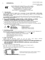
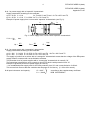


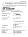
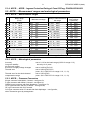
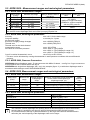
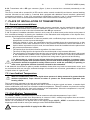
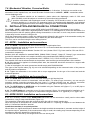


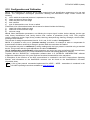

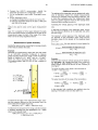
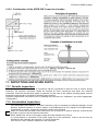

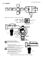
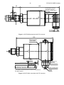
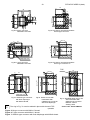


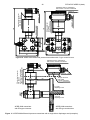

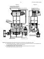
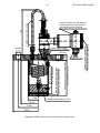
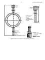
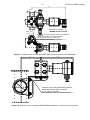
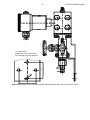
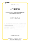
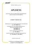
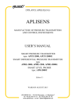


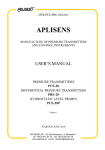

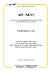
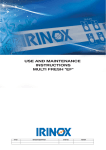

![[17] User`s Manual ver. 2.0.2](http://vs1.manualzilla.com/store/data/005765389_1-e376d351ef2708f30fcfdc5f98b9ba18-150x150.png)