1
User Manual
Cine-tal Systems, Inc.
8383 Craig Street
Suite 130
Indianapolis, IN 46250
Cinemage User Manual
Version 2.1
1
FCC Notice
This device complies with Part 15 of the FCC
Rules. To assure continued compliance follow
the attached installation instructions and do
not make any unauthorized modifications.
This equipment has been tested and found
To comply with the limits for a class A digital
Device, pursuant to Part 15 of the FCC
Class rules. These limits are designed to
Provide reasonable protection against
harmful interference when the equipment is
operated in a commercial environment. This
equipment generates, uses, and can radiate
radio frequency energy and, if not installed and
used in accordance with the instruction manual,
may cause harmful interference to radio
communications. Operation of this equipment
in a residential area is likely to cause harmful
interference in which the user will be required
to correct the interference at his own expense.
WARNING:
TO REDUCE THE RISK OF FIRE OR
SHOCK HAZARD, DO NOT EXPOSE THIS
EQUIPMENT TO RAIN OR MOISTURE.
CAUTION:
TO REDUCE THE RISK OF FIRE OR
SHOCK HAZARD AND ANNOYING
INTERFERENCE, USE THE
RECOMMENDED ACCESSORIES ONLY.
Cinemage User Manual
Version 2.1
2
Preface
This User’s Guide includes instruction and reference information for the operation
and use of:
Cinemage 2142
Cinemage 2122
Cinemage 2042
Cinemage 2022
All options available for the Cinemage line of products.
Trademarks
All brand and product names mentioned herein are used for information
purposes only and may be trademarks or registered trademarks of their
respective companies.
Cinemage User’s Guide
Copyright © 2005 Cine-tal Systems, LLC
All Rights Reserved
Reproduction, adaptation, or translation of this document without prior permission
is prohibited, except as allowed under copyright laws.
Printed in the United States
Note: The information in this document is subject to change without notice or obligation.
Cine-tal Systems, LLC
REV A
Cinemage User Manual
Version 2.1
3
Table of Contents
Official Notices .............................................................................................. 7
Limitation of Liability .................................................................................................. 7
Software License Agreement ....................................................................................... 7
Cine-tal Hardware Warranty ...................................................................................... 8
Cine-tal Software Warranty ........................................................................................ 9
Section 1: Getting Started .......................................................................... 11
Chapter 1: Introduction ............................................................................................. 11
Welcome!....................................................................................................11
How to use this guide................................................................................11
Block Diagram............................................................................................13
Front Panel .................................................................................................14
Rear Panel ..................................................................................................14
Power Requirements .................................................................................14
User Serviceable Parts ..............................................................................14
Turning On The System ............................................................................14
Chapter 2: Menu Overview........................................................................................ 15
Main Menu ..................................................................................................15
Operator Menus .........................................................................................16
System Menus............................................................................................19
Setup Menus ..............................................................................................21
Lockout Menu ............................................................................................22
Section 2: Setting Up Your System ........................................................... 23
Chapter 3: Setup Overview........................................................................................ 24
Setup Menus ..............................................................................................24
Chapter 4: Unit Information Menus ......................................................................... 25
Chapter 5: Video & Display Setup ............................................................................ 27
Video Setup ................................................................................................27
Display Calibration ....................................................................................27
Dual Link.....................................................................................................27
Sync Source ...............................................................................................28
Current Format...........................................................................................28
SDI Timing ..................................................................................................28
Input Limiting Mode...................................................................................28
Chapter 6: Display Calibration ................................................................................. 29
Auto Calibrate ............................................................................................29
Manual Calibration.....................................................................................29
Measure ......................................................................................................40
Steps to calibrate your display.................................................................41
Chapter 7: Preset / Preferences Setup ...................................................................... 42
Introduction to Presets and Preferences.................................................42
Manage Preferences ..................................................................................43
Manage Presets .........................................................................................45
Startup Settings .........................................................................................45
Chapter 8: USB Datakey Setup ................................................................................ 46
Cinemage User Manual
Version 2.1
4
Format and Prepare USB ..........................................................................46
Clone System To/From USB .....................................................................46
USB file Copy .............................................................................................47
Setup Lockout with USB Key....................................................................47
Updates: .....................................................................................................47
USB File Copy Menu:.................................................................................47
Updates Menu: ...........................................................................................47
Web / FTP Setup ........................................................................................49
Remote File Setup......................................................................................50
File Sharing ................................................................................................51
Wired Wireless Setup ................................................................................52
Steps to connect Cinemage to a network router. ...................................53
Chapter 10: System Reset .......................................................................................... 55
Reset to Defaults .......................................................................................55
Factory Reset .............................................................................................55
Section 3: Using Your System.................................................................... 56
Chapter 11: Routing .................................................................................................. 57
Display Source...........................................................................................57
DVI Input Fullmode ....................................................................................57
V1 Out Source ............................................................................................57
V2 Out Source ............................................................................................57
Dual Link Mode ..........................................................................................57
Chapter 12: Process / Framestore ............................................................................ 58
Framestore: Menu 1...................................................................................58
Framestore: Menu 2...................................................................................59
Framestore: Still File Management Menu ................................................60
Framestore: Setup .....................................................................................61
Chapter 13: Process / Colourgrade ........................................................................... 64
3D LUT Source ...........................................................................................64
Display Source...........................................................................................64
Browse 3D LUTs ........................................................................................64
Load LUT Now............................................................................................64
Chapter 14: Process / Input LUTs............................................................................. 65
Input LUT 1&2 ........................................................................................................... 66
Process Menu: Input LUTs: Input LUTs 1&2 ......................................................... 66
Load Input LUT 1....................................................................................................... 66
Chapter 15: Process/Pan and Zoom.......................................................................... 67
Chapter 16: Display / Cages (Graticules) ................................................................. 69
Cages Enabled:..........................................................................................69
Cages Setup ...............................................................................................69
Mask Setup.................................................................................................70
Chapter 17: Display/ Heads Up Display ................................................................... 71
Chapter 18: Display / Split Screen ............................................................................ 72
Chapter 19: Display / Scaler & Deinterlacer........................................................... 73
Chapter 20: Display/ Test Pattern Generator .......................................................... 74
Chapter 21: Analyse / Pixel Data Analysis ............................................................... 76
Cinemage User Manual
Version 2.1
5
Chapter 22: Analyse / Pixel Analysis / Pan and Zoom ............................................ 78
Chapter 23: Analyse / Waveform Monitor............................................................... 79
Chapter 24: Analyse / Waveform Setup ................................................................... 81
Chapter 25: Analyse / Vectorscope Setup................................................................. 83
Section 4: SD Operations ........................................................................... 84
Appendix A: USEFUL OPERATIONS ................................................... 85
Cine-tal Cinemage Preferences Control: .................................................................. 85
Setting Remote File Locations ................................................................................... 85
Saving a preference: ................................................................................................... 87
Saving a Preset: ........................................................................................................... 88
Cloning to/from a USB key: ....................................................................................... 90
Software Updates/Upgrades: ..................................................................................... 92
Accessing a router:...................................................................................................... 94
Remote File Setup:...................................................................................................... 96
Calibration: ................................................................................................................. 97
DVI Input Release Notes ............................................................................ 99
Cinemage User Manual
Version 2.1
6
Official Notices
Limitation of Liability
CINE-TAL SYSTEMS LLC SHALL NOT BE LIABLE FOR INDIRECT, SPECIAL, INCIDENTAL,
OR CONSEQUENTIAL DAMAGES; FOR DAMAGES THAT DIRECTLY OR INDIRECTLY ARISE
FROM YOUR USE OF, OR INABILITY TO USE, THE SYSTEM; FOR COMMERCIAL LOSS OF
ANY KIND; FOR THE PROCUREMENT OF SUBSITIUTE GOODS—WHETHER ARISING IN
TORT, CONTRACT OR ANY OTHER LEGAL THEORY, EVEN IF CINE-TAL SYSTEMS LLC
HAS BEEN ADVISED OF THE POSSIBILITY OF SUCH DAMAGES. IN ANY EVENT, CINE-TAL
SYSTEMS LLC’S LIABILITY SHALL BE LIMITED TO THE AMOUNT ACTUALLY PAID BY YOU
FOR THE SYSTEM GIVING RISE TO ANY SUCH DAMAGE. THIS LIMITATION IS INTENDED
TO LIMIT CINE-TAL SYSTEMS LLC’s LIABILITY AND SHALL NOTWITHSTANDING ANY
FAILURE OF ESSENTIAL PURPOSE OF ANY LIMITED REMEDY.
Software License Agreement
IMPORTANT-READ CAREFULLY: This Software License Agreement is a legal agreement
between Cine-tal’s Customer and Cine-tal Systems LLC. This system contains certain Cine-tal
Systems computer software, hardware, associated media, printed materials, and electronic
documentation. By using the system described in this manual, The Customer agrees to be bound
by the terms of this Software License Agreement. If The Customer does not agree to the terms of
this Software License Agreement, Cine-tal Systems LLC is unwilling to license the Software to
The Customer. In such case, The Customer may not use or copy the Software. This system also
contains certain third party software licenses included and contained with the materials shipped
with the system.
License: Cine-tal Systems LLC grants a nonexclusive, personal, perpetual,
nontransferable, limited license to use the installed Software exclusively on hardware on
which Cine-tal Systems LLC has installed the Software, or on hardware on which Cine-tal
Systems LLC has authorized it to be installed,. Such Software may only be enabled,
modified or updated by Cine-tal Systems LLC or its authorized agent. Cine-tal Systems
LLC and its licensors retain the right, title, and interest in and to all Software. Title to the
media on which the Software is delivered is transferred to the Customer.
Restrictions: The Software is copyrighted and may contain material that is protected by
patent, trade secret or other laws pertaining to proprietary rights. You may not copy the
Software, except that you may make a single copy for archival purposes. You may not
modify the Software or permit or assist any third party in doing so. You may not
decompile, reverse engineer, disassemble, or otherwise reduce the Software to source
code or other human-readable form, or attempt or permit any third party to do so. Any
violation of this Software license shall be a material breach and shall immediately entitle
Cine-tal Systems LLC to exercise any remedy that may exist at law or in equity.
Copyright: All title and copyrights in the Software (and any copies thereof) and the
accompanying printed materials are owned by Cine-tal Systems LLC. All rights not
specifically granted under this Software License Agreement are reserved by Cine-tal
Systems LLC.
Cinemage User Manual
Version 2.1
7
Cine-tal Hardware Warranty
(a) Company warrants to the original purchaser of Equipment that for the Warranty
Period (as defined below), the Equipment will be free from material defects in materials
and workmanship. The foregoing warranty is subject to the proper installation, operation
and maintenance of the Equipment in accordance with installation instructions and the
operating manual supplied to Customer. Warranty claims must be made by Customer in
writing within sixty (60) days of the manifestation of a problem. Company's sole obligation
under the foregoing warranty is, at Company's option, to repair, replace or correct any
such defect that was present at the time of delivery, or to remove the Equipment and to
refund the purchase price to Customer.
(b) The "Warranty Period" begins on the date the Equipment is delivered and
continues for 12 months.
(c) Any repairs under this warranty must be conducted by an authorized Company
service representative at an authorized repair facility. The customer is responsible for
costs associated with shipping the equipment to and from an authorized repair facility.
(d) This warranty is for the hardware and hardware sub-systems of the equipment
and specifically excluded from the warranty is all software, (which is covered under the
software warranty), problems due to accidents, misuse, misapplication, storage damage,
negligence, or modification to the Equipment or its components.
(e) Company does not authorize any person or party to assume or create for it any
other obligation or liability in connection with the Equipment except as set forth herein.
(f) THE WARRANTY IN SECTION 6(a) ABOVE IS EXCLUSIVE AND IN LIEU OF ALL
OTHER INDEMNITIES OR WARRANTIES, WHETHER EXPRESS OR IMPLIED, INCLUDING
THE IMPLIED WARRANTIES OF MERCHANTABILITY AND FITNESS FOR A PARTICULAR
PURPOSE.
Limitation of Liability. IN NO EVENT SHALL COMPANY BE LIABLE FOR ANY INDIRECT,
INCIDENTAL, PUNITIVE, SPECIAL OR CONSEQUENTIAL DAMAGES, OR DAMAGES FOR
LOSS OF PROFITS, REVENUE, OR USE INCURRED BY CUSTOMER OR ANY THIRD
PARTY, WHETHER IN AN ACTION IN CONTRACT, OR TORT, OR OTHERWISE EVEN IF
ADVISED OF THE POSSIBILITY OF SUCH DAMAGES. COMPANY'S LIABILITY FOR
DAMAGES ARISING OUT OF OR IN CONNECTION WITH THIS AGREEMENT SHALL IN NO
EVENT EXCEED THE PURCHASE PRICE OF THE DEFECTIVE EQUIPMENT. THE
PROVISIONS OF THIS AGREEMENT ALLOCATE THE RISKS BETWEEN COMPANY AND
CUSTOMER. COMPANY'S PRICING REFLECTS THIS ALLOCATION OF RISK AND BUT
FOR THIS ALLOCATION AND LIMITATION OF LIABILITY, COMPANY WOULD NOT HAVE
ENTERED INTO THIS AGREEMENT.
Cinemage User Manual
Version 2.1
8
Cine-tal Software Warranty
Cine-tal represents and warrants that the Software shall perform substantially as
represented in the Documentation.
WARRANTY LIMITATION: THE FOREGOING WARRANTY IS IN LIEU OF ALL OTHER
WARRANTIES, EXPRESSED OR IMPLIED, INCLUDING BUT NOT LIMITED TO, IMPLIED
WARRANTIES OF FITNESS FOR A PARTICULAR PURPOSE AND WARRANTIES OF
MERCHANTABILITY. EXCEPTING THE WARRANTY EXPRESSLY ACKNOWLEDGED
HEREUNDER, CINE-TAL HEREBY DISCLAIMS AND CUSTOMER HEREBY WAIVES ALL
WARRANTIES, EXPRESS OR IMPLIED, INCLUDING BUT NOT LIMITED TO ALL IMPLIED
WARRANTIES OF FITNESS FOR A PARTICULAR PURPOSE AND ALL IMPLIED
WARRANTIES OF MERCHANTABILITY.
Limitation of Damages: Cine-tal shall not be liable to Customer under the Warranty for any
consequential, exemplary, incidental or punitive damages, regardless of whether Cine-tal
has been advised of the possibility of such damages in advance or whether such damages
are reasonably foreseeable.
Force Majeure: Cine-tal shall not be liable to Customer for failing to perform its
obligations under the Agreement because of circumstances beyond the control of
Customer. Such circumstances shall include, but not be limited to, any acts or omissions
of any government or governmental authority, natural disaster, act of a public enemy, riot,
sabotage, dispute or differences with workmen, power failure, delays in transportation or
deliveries of supplies or materials, acts of God, terrorism, or any events reasonably
beyond the control of Customer.
Indemnification: Customer shall release, defend, indemnify and hold harmless Cine-tal
from and against any claims, damages and liability arising from use of the Software or
Documentation by Customer.
To Obtain Warranty Service and Customer Support
The following information describes our current warranty support procedures. These
procedures are subject to change without notice and are expressly excluded from the
Limited Warranty.
•
Our Customer Support Representatives are available to provide telephone support
during business hours (M-F, 8am-8pm EST), and after these hours for urgent
“emergency” technical support.
•
Before returning the Product for repair or replacement, it is necessary to obtain a Return
Merchandise Authorization (RMA) number by calling (317) 576-0091. You will be asked
to provide the system’s serial number (or a copy of the invoice showing date of original
purchase) and/or the Hardware Maintenance Agreement number.
•
In order to provide you with an exchange unit in advance of receiving the nonfunctioning unit, we will need (i) a company purchase order for the value of the unit
being provided (ii) the serial number of the component being returned. Your PO will not
be billed if the non-functioning unit is returned as described below within 7 days.
•
The non-functioning part should be properly packed and shipped pre-paid to CINE-TAL
with the RMA number clearly displayed on the outside of the package and on the
Cinemage User Manual
Version 2.1
9
accompanying RMA form. We will refuse to accept any package without a valid RMA
number.
•
Normal labor, material, and shipping charges will apply to repairs outside the scope of
the Limited Warranty.
This product includes some software from the GraphicsMagick Group. Cine-tal wishes
to thank all the GraphicsMagick contributors and especially Bob Friesenhahn.
Copyright (C) 2003 GraphicsMagick Group, an organization dedicated to making
software imaging solutions freely available.
Permission is hereby granted, free of charge, to any person obtaining a copy of this
software and associated documentation files ("GraphicsMagick"), to deal in
GraphicsMagick without restriction, including without limitation the rights to use, copy,
modify, merge, publish, distribute, sublicense, and/or sell copies of GraphicsMagick, and
to permit persons to whom GraphicsMagick is furnished to do so, subject to the following
conditions:
The above copyright notice and this permission notice shall be included in all copies or
substantial portions of GraphicsMagick.
The software is provided "as is", without warranty of any kind, express or implied,
including but not limited to the warranties of merchantability, fitness for a particular
purpose and noninfringement. In no event shall GraphicsMagick Group be liable for any
claim, damages or other liability, whether in an action of contract, tort or otherwise,
arising from, out of or in connection with GraphicsMagick or the use or other dealings in
GraphicsMagick.
Except as contained in this notice, the name of the GraphicsMagick Group shall not be
used in advertising or otherwise to promote the sale, use or other dealings in
GraphicsMagick without prior written authorization from the GraphicsMagick Group.
Cinemage User Manual
Version 2.1
10
Section 1: Getting Started
Chapter 1: Introduction
Welcome!
The Cinemage product family revolutionizes critical monitoring for digital cinema
acquisition, post production and DI by combining Cine-tal’s leading edge IDS (Intelligent
Display Server) technology and calibrated full resolution LCD display. Cinemage
provides quantitative video analysis, colour pre-visualization, video signal quality
assurance, real-time collaboration between acquisition and post production, and an
integrated OmniTek™ Waveform Monitor and Vectorscope. With Cinemage you can
conduct both critical visual analysis and digital quantitative analysis of your HD SDI or
HD SDI Dual Link signal in either YCbCr or RGB, linear or logarithmic, at 8 or 10 bits.
IDS Technology is a joint technology development between Cine-tal and OmniTek. IDS
provides image processing, signal routing, frame stores, and colour manipulation (3D
LUT’s) and test and measurement all in a network appliance configuration. Internal to
IDS is a powerful image processor that generates real-time data about the HD video
stream. This data is used to generate waveforms, vectorscopes, gamut information and
status of the incoming video signal. IDS also provides for display calibration and
profiling as well as input signal colour grading for pre-visualization. All data and
operations can be performed over a LAN, WAN or wireless network with any webenabled device.
How to use this guide
This Cinemage User Guide is intended to be a learning tool for those new to the
Cinemage product as well as a handy reference for experienced operators. The User’s
Guide offers step by step instructions and general information.
If you are new to the Cinemage products we strongly suggest that you read this manual
completely and familiarize yourself with all the tasks presented. An investment in time
now may save a lot of time later.
Cinemage User Manual
Version 2.1
11
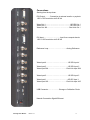
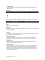
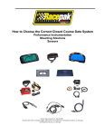
Connections
Starting from the top down:
DVI Output……….Connection to external monitor or projector
1920 x 1200 resolution at 48-60 Hz
Video Out 1………………………………………..HD SDI Out 1
Video Out 2………………………………………..HD SDI Out 2
Video Out 1&2……………………………….….Dual Link Out 1
DVI Input………………………….Input from computer device
1920 x 1200 resolution at 48-60 Hz
Reference Loop…………………………….Analog Reference
Video Input 4……………………………….….HD SDI Input 4
Video Input 3…………………………………..HD SDI Input 3
Video Input 3&4…………………………….Dual Link Input 3&4
Video Input 2………………………….……….HD SDI Input 2
Video Input 1………………………………….HD SDI Input 1
Video Input 1&2…………………………….Dual Link Input 1&2
USB Connector……….………..Storage or Calibration Probe
Network Connection Gigabit Ethernet
Cinemage User Manual
Version 2.1
12
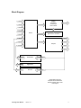
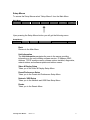
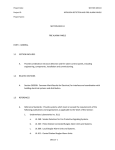
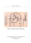
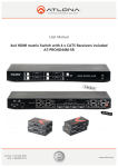
Block Diagram
HD SDI 1
HD SDI 2
All Input Signals
Display
Waveform
Vectorscope
Pan & Zoom
DVI OUTPUT
HD SDI 3
HD SDI 4
Router
All Input Signals
Split Screen Generator
DVI Input
3D LUT
HD SDI 1
Signal Gen.
All Input Signals
HD SDI 2
Outputs
FrameStore
HD SDI 3
HD SDI 4
To Router Inputs
To Router Inputs
To Router Inputs
Framestore
All Output Signals
Signal Gen
3D LUT
All Output Signals
All HD SDI Inputs and
Outputs can be linked as 2
Dual Link Inputs and 1 Dual
Link Output
Cinemage User Manual
Version 2.1
13
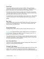
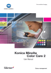
Front Panel
There are 6 pushbuttons located on the Front Panel. These pushbuttons
correspond to the soft menus located above each button. These pushbuttons
allow for direct input to the various features of the Cinemage Monitor.
The menus are located in the lower unused portion of the active video screen.
The upper unused portion of the active video screen is used as a reference bar
going from black to white across the top of the screen.
A trackball located on the lower right-hand portion of the monitor. This trackball
is used for direct input for cursor positioning, alpha-numeric input and level
setting.
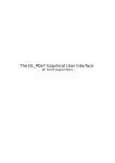
Rear Panel
The rear panel is the location of the On/Off switch, the input AC connector and
the 24 volt DC XLR input connector. There are also 4 threaded holes for #4
metric screws for the VESA mount.
Power Requirements
Cinemage runs on 100 to 240V AC at 50 or 60 hertz. Nominal current is 2A.
[OPTION] If you have the DC input option installed you may run the system on
22-30v dc input. Standard Anton Bauer 3 pin XLR connector is used. Pin 1 is
positive, Pin 2 is ground and pin 3 is unused.
The mains disconnect for the Cinemage system is the power connector on the
real panel of the system. The input supply socket-outlet should be located near
the device and should be easily accessible.
User Serviceable Parts
There are no user serviceable parts inside the Cinemage units. Please refer all
service to a Cine-tal authorized technician.
Turning On The System
To turn the system on simply depress the power toggle switch on the rear of the
system. Note: To protect the system from erratic power outages the system
requires a 10 second wait period between power down and immediate power up.
Cinemage User Manual
Version 2.1
14
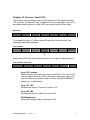
Chapter 2: Menu Overview
In reading this section note that location of menu options may change over
product revisions. Furthermore, available menu choices will vary depending on
model number and installed options. Functions that are dependent on installed
options are marked as [Option]
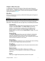
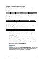
Main Menu
After the system performs a power up self test the following menu will appear at
the bottom of the display:
Main Menu
Cinemage 2142
Operator Menus
System Menus
Setup Menus
Display Controls
Presets
Original Settings
Press to lockout menus
Each menu item corresponds to one of six buttons found directly underneath
each menu. The seventh menu item (far right menu) is controlled by the trackball.
Cinemage 2142
Indicates Cinemage model number. By pressing this button once you will
navigate to the Lockout Menu. The Lockout Menu provides two
functions; 1) to blackout the non-video portion of the display and 2)
provides a key lock function such that the systems setting can’t be
changed without an unlock key (see Lockout Menu in chapter 2 for more
information.)
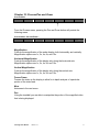
Operator Menus
The Operator Menus provide an easy menu interface for selecting the
video input, selecting internal video sources, and selecting presets of
system configurations saved as a preset. This is designed to be the menu
used during normal operation of the monitor.
System Menus
The System Menus navigates the user to the full system menus including
all route, process, display, analyze and setup functions.
Setup Menus
The Setup Menus navigates the user to all system setup functions and to
the system reset.
Display Controls
Will enter the Display Control Menu, allowing you to display
characteristics; such as brightness, contrast, gamma, and backlight
brightness.
Presets
Allows you to toggle Presets previously saved into the system.
Cinemage User Manual
Version 2.1
15
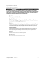
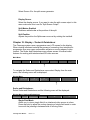
Operator Menus
To access the Operator Menus select “Operator Menus” from the Main Menu
Main Menu
Cinemage 2142
Operator Menus
System Menus
Setup Menus
Display Controls
Presets
Original Settings
Press to lockout menus
↑
Upon pressing the Operators menu button you will get the following menu:
Operator MenusÆ
Back
Video Input
Routing
Internal
Source
Routing
Presets
3D LUTS
Stills
Operator Menu
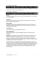
Upon pressing the Video Input Routing Menu button you will get the following
menu:
Operator Menus: Video Input Source
Select Preset Æ
Back
SDI 1
Selected
SDI 2
SDI 3
SDI 4
DVI Input FULLMODE
Video Sources
Operator Menus: Video Input Source
Back
Returns you to the Main Menu
SDI 1
Routes SDI input 1 to the display. A highlighted button indicates the
current source that is routed to the display.
SDI 2
Routes SDI input 1 to the display. A highlighted button indicates the
current source that is routed to the display.
SDI 3
[Option]
Routes SDI input 1 to the display. A highlighted button indicates the
current source that is routed to the display.
SDI 4
[Option]
Routes SDI input 1 to the display. A highlighted button indicates the
current source that is routed to the display.
DVI INPUT FULLMODE
[Option]
Routes the DVI Input to the Display (See FSB 061220 on page 99 for
details).
Cinemage User Manual
Version 2.1
16
Menu Navigation
Use the trackball to select which operator menu to be displayed.
Operator Menus: Internal Source
Operator Menus: Internal Source
Select Internal Source Æ
Main Menu
Splitscreen
Test Pattern Generator
Framestore
3D LUT
QUAD INPUT
Internal Source
By using the trackball in the Operator Menus you can navigate to the Internal
Source menu.
Back
Returns you to the Main Menu
Splitscreen
Routes the splitscreen generator output to the display. A highlighted
button indicates the current source that is routed to the display.
Test Pattern Generator
Routes the Test Pattern Generator output to the display. A highlighted
button indicates the current source that is routed to the display.
Framestore
Routes the Framestore output to the display. A highlighted button
indicates the current source that is routed to the display.
3D LUT
Routes the 3D LUT output to the display. A highlighted button indicates
the current source that is routed to the display.
QUAD INPUT
[Option]
Displays all four HD-SDI inputs at the same time in a ¼ screen resolution
Cinemage User Manual
Version 2.1
17
Operator Menus: Presets
Operator Menus: Presets Menu
Select Preset Æ
Operator Menu
Save New Preset
Defaults
Original
Settings
Preset 0
More Presets
Preset s 1
By using the trackball in the Operator Menus you can navigate to the Presets
menus. Each Preset menu page contains 5 presets starting with Original Settings
and Defaults. There are 20 Presets available in the system. Use the trackball to
advance the Operators Menus the next Presets page.
Main Menu
Returns you to the Main Menu
Save New Preset
Will save your settings to the next available Preset. This new Preset can
be renamed in the Manage Presets menu
Defaults
Restores the system to the settings you had before you selected a Preset.
This would include any setup changes made from the time of power up.
Original Settings
This restores the system to the settings loaded at the time of power-up.
Power-up settings are settings saved from the previous power down.
Preset 0
Selects the first of the user defined presets.
More Presets
Moves forward to the next Presets menu
Cinemage User Manual
Version 2.1
18
Operator Menus: Stills
Operator Menus: Stills
Select Still Æ
Operators Menu
Still 1
Still 2
Still 3
Still 4
Stills 1
More Stills
By using the trackball in the Operator Menus you can navigate to the Stills
menus. Each Stills menu page contains 5, Stills. There are 20 Stills available in
the system. Use the trackball to advance the Operators Menus the next Stills
page. The Operators Menu returns you to the Operators Menu
Operator Menus: 3D LUTs
Operator Menus: 3D LUTs
Select 3D LUT Æ
Operators Menu
Reset
3D LUT 1
3D LUT 2
3D LUT 3
3d LUT 1
More 3d LUTs
By using the trackball in the Operator Menus you can navigate to the 3D LUTs
menus. Each 3D LUT menu page contains 5, 3D LUTs. There are 20 3D LUTs
available in the system. Use the trackball to advance the Operators Menus the
next 3D LUTs page. The Operators Menu returns you to the Operators Menu
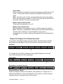
System Menus
To access the System Menus select “System Menus” from the Main Menu
Main Menu
Cinemage 2142
Operator Menus
System Menus
Setup Menus
Display Controls
Presets
Backlight:
Original Settings
20.5%
Press to lockout menus
↑
Upon pressing the System Menus button you will get the following menu:
System menu
Back
Route
Process
Display
Analyse
Presets:
Route
The routing menu routes system video signals to the display, HD-SDI
Outputs,, and 3D LUT, and allows for toggling of Dual Link Mode [Option].
Process
The Process menu allows the user access to the Framestores, Colour
Grade Menu, Input LUTs, and Pan and Zoom Menus.
Display
Cinemage User Manual
Version 2.1
19
The Display Menu allows the user access Cage (Graticule) Generators,
the Head-Up Display, Motion Compensation and the Test Pattern
Generator [Option].
Analyse
[Option]
The Analyse Menu allows the user access to the Pixel Data Analysis,
Waveform and Vectorscope, Display Output Measurement, Range and
Gamut Violations, and Input Status menus.
Presets
The Preset Menu allows the user quick access to various Preset
operational conditions. 20 Presets can be stored on the system. These
Presets can also be stored to a USB memory stick, or on a network file
server.
Cinemage User Manual
Version 2.1
20
Setup Menus
To access the Setup Menus select “Setup Menus” from the Main Menu
Main Menu
Cinemage 2142
Operator Menus
System Menus
Setup Menus
Display Controls
Presets
Backlight:
Original Settings
20.5%
Press to lockout menus
↑
Upon pressing the Setup Menus button you will get the following menu:
Setup Menus
Back
Unit
Information
Video & Display
Setup
Preset/ Preferences Setup
Network / USB Datakey Setup
Resets
Back
Returns to the Main Menu
Unit Information
The Unit Information navigates the user to the menus providing
information on the unit including software version, IP Address, MAC
Address, TCP/IP machine name, software options installed, diagnostics,
network status, and software update and restore menus.
Video & Display Setup
Takes you to the Video & Display Setup Menu
Preset/Preferences Setup
Takes you to the Preset and Preferences Setup Menu
Network / USB Setup
Takes you to the Network and USB Data Setup Menu
Resets
Takes you to the Resets Menu.
Cinemage User Manual
Version 2.1
21
Lockout Menu
To access the Lockout Menu the user must press the Top Menu’s first button
“Model Number”.
Main Menu
Cinemage 2142
Operator Menus
System Menus
Setup Menus
Display Controls
Presets
Original Settings
Press to lockout menus
↑
Upon pressing the system model number button you will get the following menu:
Cinemage 2142
Back
Blackout
Lockout
Blackout and
Lockout
Blackout Top
Keyed Lockout
Back
Returns you to the Main Menu
Blackout
Removes the upper reference bar and menus. The menus can be re-activated by
pressing any button.
Lockout
Locks access to the menu buttons. Access is re-activated by pressing this button
for 5 seconds then releasing the button.
Blackout & Lockout
Performs both a blackout and a lockout. The menus can be re-activated by
pressing button number 6 (far right button) for five seconds then releasing.
Blackout Top
Applies a solid black field to the upper segment of the display, disabling the
default luma ramp typically displayed.
Keyed Lockout
Locks access to the menu buttons and writes an unlock code onto a USB data
key inserted into the system. Access is re-activated by inserting the USB
datakey into the USB slot and pressing this button. System verifies the lockout
code on the USB key and opens menu access. Lockout does not stay in force
through a system power off.
Cinemage User Manual
Version 2.1
22
Section 2: Setting Up Your System
Cinemage User Manual
Version 2.1
23
Chapter 3: Setup Overview
Setup Menus
To access the Setup Menus select “Setup Menus” from the Main Menu
Main Menu
Cinemage 2142
Operator Menus
System Menus
Setup Menus
Display Controls
Presets
Original Settings
Press to lockout menus
↑
Upon pressing the Setup Menus button you will get the following menu:
Setup Menus
Back
Unit
Information
Video & Display
Setup
Preset/ Preferences Setup
Network / USB Datakey Setup
Resets
Back
Returns to the Top Menu
Unit Information
Takes you to the Unit Information Menu
Video & Display Setup
Takes you to the Video &Display Setup Menu
Preset/Preferences Setup
Takes you to the Preset and Preferences Setup Menu
Network / USB Setup
Takes you to the Network and USB Data Setup Menu
Resets
Takes you to the Resets Menu
Cinemage User Manual
Version 2.1
24
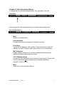
Chapter 4: Unit Information Menus
To access the Unit Information Menus select “Unit Information” from the
Setup Menus
Back
Unit
Information
Video & Display
Setup
Preset/ Preferences Setup
Network / USB Datakey Setup
Resets
↑
Upon pressing the Unit Information button you will get the following menu:
Unit Information Menus 1
Back
Unit Information:
Release 1.2 r3
IP Addresses:
192.168.1.123
MAC Addresses:
00-04-5F-82-56-A3
TCP/IP Machine name:
Cinetal-316453
More
Back
Returns to the Main Menu
Unit Information
Provides information on software and firmware versions.
I/P Address
The current I/P address for the machine. This may be either a static I/P
address or a DHCP Address. (see network setup for more information)
MAC Addresses
Display the Mac address for the systems wired and wireless network
interface (Wireless networking is an option).
TCP / IP Machine Name
Provides the UNC designator for the machine on the network. This is used
to set a network path to the machine from a network workstation.
example: //cinetal-316012
More
Takes you to Unit Information Menu 2
Cinemage User Manual
Version 2.1
25
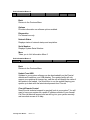
Unit Information Menus 2
Back
Options:
Secondary Inputs: Enabled
Diagnostics:
Working Set: 29.970.432.00
Network Status:
Network Startup Complete
Serial Number:
0604-316023
More
Back
Returns to the Previous Menu
Options
Provides information on software options enabled.
Diagnostics
For internal use only
Network Status
Displays status of network startup and acquisition.
Serial Number
Displays System Serial Number.
More
Takes you to Unit Information Menu 3
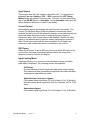
Unit Information Menus 3
Back
Update From USB:
Insert USB Key with Update
Cinetal Remote Control
Activate Now
Back
Returns to the Previous Menu
Update From USB
Updates to your system software can be downloaded from the Cine-tal
website and loaded on your USB datakey. The update facility will only
support one update at a time per key, and the unit will display the name of
the update to be loaded. Use this button to run the update keeping your
system up-to-date with the latest developments from Cine-tal.
Cine-tal Remote Control
Need Cine-tal technical support to remotely look at your system? You will
need to have your system on a public IP address outside of your firewall.
Call Cine-tal technical support and we will log into your system remotely
and see what we can do to help.
Cinemage User Manual
Version 2.1
26
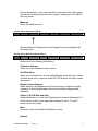
Chapter 5: Video & Display Setup
System Setup Menu
Back
Unit Information
Video & Display
Setup
Preset /Preferences
Setup
Network/USB
Setup
Reset
↑
From the System Setup menu select Video & Display Setup and you will get the
following Video & Display Setup menu:
System Setup Menu: Video & Display Setup
Back
Video Setup
Display Calibration
Video Setup
Takes you to the Video Setup Menu
Display Calibration
Takes you to the Display Calibration Menu
System Setup Menu: Video & Display Setup
Back
Video Setup
Display Calibration
↑
From the Video & Display Setup Menu, selecting Video Setup will display the
following menu:
System Setup: Video & Display Setup: Video Setup Menu
Back
Dual Link Mode:
On
Sync Source
SDI
Current Format
1080/24PsF
SDI Timing
Input 1
Input Limiting
mode
Hold and Release for setup
Dual Link
[Option]
If the system is a model 2142 or a model 2122 you will have the dual link
option installed. By setting “Dual Link Mode” to on, the inputs and outputs
of the monitor will be configured as 2 dual link inputs and 1 dual link
output. Dual Link mode will not turn on automatically when a dual link
signal is applied. You must manually select between 4:4:4 RGB Dual Link,
4:4:4 YCbCr Dual Link, or 4:2:2 YCbCr Single-Link mode.
Cinemage User Manual
Version 2.1
27
Sync Source
This function sets the sync master for the entire unit. You may choose
between Free run, Analog or SDI. If SDI is selected the SDI Timing
Master Menu will appear in the menu bar. The user can then select from
any of the HD SDI inputs or Automatic. In the Automatic mode Sync will
follow whatever valid sync is routed to the display.
Current Format
Automatically detects and displays the input format to the monitor. The
Current Format Setup Menu (Hold and release to access this menu)
provides the ability turn off the automatic detection mode and manually set
the format when using the monitor to output test pattern signals or
Framestore stills. Auto Format can only be disabled if there is no video
signal on the selected input to prevent viewing irregularities, however if
Auto Format is turned on with no video connected, it will disable the
Framestore until a valid video source is attached to the monitor.
SDI Timing
When “Sync Source” is set to SDI you can choose which SDI input is the
sync source. Automatic mode automatically selects the timing from
whatever source is routed to the display.
Input Limiting Mode
Cinemage allows you to control how the information above and below
peak white is displayed. The following choices are available:
Full Range:
Provides viewing of the full legal value data range on the display.
This means that data values below legal black are visible and data
values above legal white are visible.
Undershoot and overshoot clipped:
Clips values below legal black (16 for 8 bit data, 64 for 10 bit data)
and clips values above legal white (240 for 8 bit data, 960 for 10 bit
data).
Undershoot clipped:
Clips values below legal black (16 for 8 bit data, 64 for 10 bit data)
Cinemage User Manual
Version 2.1
28
Chapter 6: Display Calibration
From the System Setup menu select Video & Display Setup
System Setup Menu
Back
Unit Information
Video & Display
Setup
Preset /Preferences
Setup
Network/USB
Setup
Reset
↑
From the System Setup menu select Video & Display Setup and you will get the
following Video & Display Setup menu:
System Setup Menu: Video & Display Setup
Back
Video Setup
Display Calibration
↑
Selecting Display Calibration, you will get the following Display Setup menus:
System Setup: Video & Display Setup: Display Setup Menu
Back
Auto Calibrate
Manual
Calibration
Select calibration:
Blue Only Mode
Measure
Backlight Brightness:
20%
Auto Calibrate
[Option]
Will start the automated process of re-profiling the display by measuring
the 17 calibration points and establishing the monitor’s response curve.
Manual Calibration
This menu allows you to manually adjust the display properties in a similar
fashion to the conventional calibration found on CRT monitors.
Adjustments made in this menu can be saved by overwriting one of the
existing display profiles. For best results, Manual Calibration should be
performed after an Auto Calibration to achieve your optimal monitor
response curve.
Select Calibration
Cycles through the factory and user customized display profiles.
Blue Only Mode
Cinemage User Manual
Version 2.1
29
Causes the display to only output the Blue component of the video signal.
Can be used to ensure proper monitor setup by viewing the Color Bars in
blue only mode.
Measure
Enters the Measure menu
System Setup: Display Setup Menu
Back
Auto Calibrate
Manual
Calibration
Select Calibration
Blue Only Mode
Measure
Backlight Brightness:
20%
↑
Selecting Manual Calibration from the Display Setup menu displays the
following menu:
Display Setup: Manual Calibration Menu 1
Back
Calibration
Options
Set White Point
Brightness
and Contrast
Adjust x,y, R,G,B
Bias and Gain
More
Gamma:
2.20
Back
Returns you to the Display Setup Menu
Calibration Options
Takes you to the Calibration options menu.
Set White Point
Allows you to choose from 12 user definable white point settings, or select
a custom white point, as well as select the CIE Observer for each of these
white points.
Brightness and Contrast
Allows access to the Brightness and Contrast menu to adjust the digital
emulation of the brightness and contrast of the display during manual
calibration.
Adjust x,y,R,G,B Bias and Gain
Accesses the menu to control the Display biases towards displaying R, G,
and B values, as well as the signal gain settings for the R, G, and B
components of the signal.
More
Advances to the second Manual Calibration menu
Gamma
Cinemage User Manual
Version 2.1
30
Allows you to adjust the exponent used in the calculation of the gamma
response curve of the monitor.
Display Setup: Manual Calibration Menu 1
Back
Calibration
Options
Set White Point
Brightness
and Contrast
Adjust x,y, R,G,B
Bias and Gain
More
Gamma:
2.20
↑
Selecting Set White Point and Gamma will display the following menu:
Display Setup: Manual Calibration Menu 1: Set White Point
Back
Update Display
Profile
Colour
Temperature
Observer
Update Display Profile
Performs a new auto calibration of the display.
Colour Temperature
Allows you to select from 12 user definable white points, or select a
custom white point. The Custom white point moves in steps of 100°K,
and ranges from 4000°K to 9800°K, and is controlled by the trackball to
the right.
Observer
Selects the observer of 10 degrees (CIE 1962) or 2 degrees (CIE
1931). If you don’t know what this means please leave it at 2 degrees.
Cinemage User Manual
Version 2.1
31
Display Setup: Manual Calibration Menu 1
Back
Calibration
Options
Set White Point
Brightness
and Contrast
Adjust x,y, R,G,B
Bias and Gain
More
Gamma:
2.20
↑
Pressing the Brightness and Contrast button will display the following
menu:
Display Setup: Manual Calibration Menu 1:Brightness and Contrast
Back
Reset Brightness
Reset Contrast
Brightness
Contrast
Brightness
0
Back
Returns you to the Manual Calibration menu
Reset Brightness
Resets any adjustments made to the brightness setting back to
their original position.
Reset Contrast
Resets any adjustments made to the contrast setting back to their
original position.
Brightness
Selects the brightness setting for adjustment controlled by the
trackball to the right of the monitor.
Contrast
Selects the contrast setting for adjustment controlled by the
trackball at the right of the monitor.
Special Note about Brightness and Contrast
Cinemage emulates the contrast control of a CRT by manipulating
the response of the LCD; due to the nature of LCD technology
contrast and brighness will start clipping very quickly when these
controls are manipulated up. In the general case you will get a
better result by manipulation of the backlight and gamma than with
the Brightness and Contrast, as backlight and gamma are native
LCD controls, not emulated CRT controls.
Cinemage User Manual
Version 2.1
32
Display Setup: Manual Calibration Menu 1
Back
Calibration
Options
Set White Point
Brightness
and Contrast
Adjust x,y, R,G,B
Bias and Gain
More
Gamma:
2.20
↑
Pressing the Adjust x, y, R, G, B Bias and Gain will give you the following menu:
Display Setup: Manual Calibration Menu 1: x,y,R,G,B Bias and Gain menu 1
Back
Red Bias
Green Bias
Blue Bias
More
Flat Field Display
Red Bias
0
Back
Takes you back to the second Manual Calibration menu.
Red Bias
Allows you to adjust the monitor’s response curve upward for the
Red component by using the trackball located at the right of the
monitor. Effects of the bias adjustment will be more visible towards
the black end of the shading spectrum.
Green Bias
Allows you adjust the monitor’s response curve upwards for the
Green component by using the trackball located at the right of the
monitor. Effects of the bias adjustment will be more visible towards
the black end of the shading spectrum.
Blue Bias
Allows you to adjust the monitor’s response curve upwards for the
Blue component by using the trackball located at the right of the
monitor. Effects of the bias adjustment will be more visible towards
the black end of the shading spectrum.
More
Advances to the next menu
Flat Field Display
Sets the display to a flat field of black, 17 progressively brighter
shades of grey, 100% white, 100% red, 100% green, and 100%
blue for display measurement and calibration.
Cinemage User Manual
Version 2.1
33
Display Setup: Manual Calibration Menu 2: x,y,R,G,B Bias and Gain menu 1
Back
Red Bias
Green Bias
Blue Bias
More
Flat Field Display
Red Bias
0
↑
Pressing the More button will display the following menu:
Display Setup: Manual Calibration Menu 2: x,y,R,G,B Bias and Gain menu 2
Back
Red gain
Green Gain
Blue Gain
More
Flat Field Display
Red Bias
0
Back
Returns to the x,y,R,G,B Bias and Gain menu 1
Red Gain
Adjusts the monitor’s response curve by adding a multiplier to the
red component curve by using the trackball to the right of the
monitor. Effects of the adjustment to gain settings will be more
visible towards the white end of the shading spectrum.
Green Gain
Adjusts the monitor’s response curve by adding a multiplier to the
green component curve by using the trackball to the right of the
monitor. Effects of the adjustment to gain settings will be more
visible towards the white end of the shading spectrum.
Blue Gain
Adjusts the monitor’s response curve by adding a multiplier to the
blue component curve by using the trackball to the right of the
monitor. Effects of the adjustment to gain settings will be more
visible towards the white end of the shading spectrum.
More
Advances to the next menu.
Set Flat Field
Sets the display to a flat field of black, 17 progressively brighter
shades of grey, 100% white, 100% red, 100% green, and 100%
blue for display measurement and calibration.
Cinemage User Manual
Version 2.1
34
Display Setup: Manual Calibration Menu 2: x,y,R,G,B Bias and Gain menu 2
Back
Red gain
Green Gain
Blue Gain
More
Red Bias
0
Flat Field Display
↑
Pressing the More button will display the following menu:
Display Setup: Manual Calibration Menu 2: x,y,R,G,B Bias and Gain menu 3
x,y
0,0
Back
Back
Returns you to x,y,R,G,B Bias and Gain menu 2.
x,y
This trackball controlled menu item allows you to adjust the x and y
color coordinates for the entire monitor response curve.
Adjustments will be displayed in the format of Δx, Δy.
Setup: Manual Calibration Menu 1
Back
Calibration
Options
Set White Point
Brightness
and Contrast
Adjust x,y, R,G,B
Bias and Gain
More
Gamma:
2.20
↑
Pressing the More button on the Manual Calibration menu will advance to the
second Manual Calibration menu and display:
Display Setup: Manual Calibration Menu 2
Back
Adjust High, Mid,
Low
Adjust Detailed
Calibration Points
Reset
Adjustments
Calibration to
Overwrite
Save Calibration Now:
Back
Returns you to Manual Calibration menu 1
Adjust High, Mid, low
Accesses the menu allowing you to adjust the x, y, Y, R, G, and B
values of the points along gamma curve. Adjustments are made to
the gamma curve sections divided into low (1/3 closest to black),
mid, and high (1/3 closest to white).
Adjust Detailed Calibration Points
Cinemage User Manual
Version 2.1
35
Accesses the menu to make x, y, Y, R, G, and B values to each of
the 17 points along the gamma curve that Cinemage identifies for
profiling the monitor.
Reset Adjustments
Resets all of the calibration changes that you have made to the
monitor in the Manual Calibration menu. Changes made to the
calibration profiles will have to be reset using this button as they will
not be reset using the Reset menu found in the Setup menu.
Calibration to Overwrite
Selects from one of the 5 custom calibration profiles or from the
user definable REC 709, DCI, or Linear profiles to overwrite with
your manual adjustments.
Save Calibration Now
Saves your manual changes to the calibration profile that you have
elected to overwrite.
Display Setup: Manual Calibration Menu 2
Back
Adjust High, Mid,
Low
Adjust Detailed
Calibration Points
Reset
Adjustments
Calibration To
Overwrite
Save Calibration Now:
↑
Pressing the Adjust High, Mid, Low will give you the following menu:
Display Setup: Manual Calibration Menu 2: Adjust High, Mid, Low menu 1
Back
Segment to Modify
High
Adjust x
Adjust y
Adjust Y
More
Adjust x
0
Back
Returns to the Manual Calibration menu 2.
Segment to Modify:
Selects either the High, Mid, or Low segment of the monitor’s
response curve to make adjustments to. High refers to the 1/3 of
the curve closest to white, and Low refers to the 1/3 of the curve
closest to black.
Adjust x
When selected, this button allows you to use the trackball to the
right of the monitor to make adjustments to the x color coordinate
for the selected segment of the monitor’s response curve.
Cinemage User Manual
Version 2.1
36
Adjust y
When selected, this button allows you to use the trackball to the
right of the monitor to make adjustments to the y color coordinate
for the selected segment of the monitor’s response curve.
Adjust Y
When selected, this button allows you to use the trackball to the
right of the monitor to make adjustments to the luminance (Y)
coefficient for the selected segment of the monitor’s response
curve.
More
Advances to the next menu
Display Setup: Manual Calibration Menu 2: Adjust High, Mid, Low menu 1
Back
Segment to Modify
High
Adjust x
Adjust y
Adjust Y
More
Adjust x
0
↑
Pressing the More button will display the following menu:
Display Setup: Manual Calibration Menu 2: Adjust High, Mid, Low menu 2
Back
Segment to Modify
High
Adjust R
Adjust G
Adjust B
Adjust R
0
Back
Returns to the Adjust High, Mid, Low menu 1.
Segment to Modify:
Selects either the High, Mid, or Low segment of the monitor’s
response curve to make adjustments to. High refers to the 1/3 of
the curve closest to white, and Low refers to the 1/3 of the curve
closest to black.
Adjust R
When selected this button allows you to use the trackball to the
right of the monitor to adjust the red component of the monitor’s
response curve for the segment selected.
Adjust G
When selected this button allows you to use the trackball to the
right of the monitor to adjust the green component of the monitor’s
response curve for the segment selected.
Cinemage User Manual
Version 2.1
37
Adjust B
When selected this button allows you to use the trackball to the
right of the monitor to adjust the blue component of the monitor’s
response curve for the segment selected.
Display Setup: Manual Calibration Menu 2
Back
Adjust High, Mid,
Low
Adjust Detailed
Calibration Points
Reset
Adjustments
Calibration To
Overwrite
Save Calibration Now:
↑
Pressing the Adjust Detailed Calibration Points will give you the following menu:
Display Setup: Manual Calibration Menu 2: Adjust Detailed Calibration Points menu 1
Back
Point to Modify
1
Adjust x
Adjust y
Adjust Y
More
Adjust x
0
Back
Takes you back to the Manual Calibration menu 2.
Point to Modify
Selects which of the 17 calibration points you would like to make
adjustments to in order modify the monitor’s response curve. If the
Flat Field generator is in use, the flat field will automatically update
to a grey field that matches the point on the curve. This allows the
user to adjust the color balance and luminance at each point.
Adjust x
When selected this button allows you to use the trackball to the
right of the monitor to make adjustments to the x color coordinate
for the calibration point you have selected.
Adjust y
When selected this button allows you to use the trackball to the
right of the monitor to make adjustments to the y color coordinate
for the calibration point you have selected.
Adjust Y
When selected this button allows you to use the trackball to the
right of the monitor to make adjustments to the Luminance (Y)
coefficient for the calibration point you have selected.
More
Advances to the next menu.
Cinemage User Manual
Version 2.1
38
Display Setup: Manual Calibration Menu 2: Adjust Detailed Calibration Points menu 1
Back
Point to Modify
1
Adjust x
Adjust y
Adjust Y
More
Adjust x
0
↑
Pressing the More button will display the following menu:
Display Setup: Manual Calibration Menu 2: Adjust Detailed Calibration Points menu 2
Back
Point to Modify
1
Adjust R
Adjust G
Adjust B
Adjust x
0
Back
Returns to the Adjust Detailed Calibration Points menu 1.
Point to Modify
Selects which of the 17 calibration points you would like to make
adjustments to in order modify the monitor’s response curve.
Adjust R
When selected this button allows you to use the trackball to the
right of the monitor to adjust the red component of the monitor’s
response curve for the calibration point selected.
Adjust G
When selected this button allows you to use the trackball to the
right of the monitor to adjust the green component of the monitor’s
response curve for the calibration point selected.
Adjust B
When selected this button allows you to use the trackball to the
right of the monitor to adjust the blue component of the monitor’s
response curve for the point selected.
Cinemage User Manual
Version 2.1
39
Measure
[Option]
This menu allows you to measure the response of the display.
System Setup: Display Setup Menu
Back
Auto Calibrate
Manual
Calibration
Select
Calibration
Blue Onle Mode
Measure
Backlight Brightness:
20%
↑
Selecting Measure from the Display Setup Menu displays the following
menu:
System Setup: Display Setup: Measure Menu
Back
xy,Y
X,Y,Y
Target: x=.314, y=.345
x=.314, y=.345, Y=115Cd
X=.314, Y=.345, Y=115 Cd
Select Calibration
Video Source
Set Flat
Field
Backlight Brightness
45%
Back
Returns you to the Display Setup Menu. Displays target CIE x,y
measurements for rec 709 or D-Cinema if selected as Display LUT.
x,y,Y
Provides result of measurement in CIE x,y,Y coordinates.
X,Y,Y
Provides result of measurement in CIE X,Y,Y coordinates.
Select Calibration
Selects one of the available stored calibrations.
Measure Now
Provides directions and starts measurements.
Note:
When using the GretagMacbeth EyeOne Design you must
calibrate the EyeOne design probe on the white tile provided with
the probe. If you are using the GretagMacbeth EyeOne Display2
Probe you may skip this step.
Set Flat Field
Sets the display to a flat field of black, 17 progressively brighter shades
of grey, 100% white, 100% red, 100% green, and 100% blue for
display measurement.
Backlight Brightness
Sets the brightness of the backlight. This should be done first to set the total
Luminance output desired for your calibration. The brightness control has 1,168
steps for accurate control of the backlight. The Measured output will be the “Y”
result read back after calibration is completed. You may use the Measure menu
located in the display setup menu to pre-set the backlight before you do your first
calibration.
Cinemage User Manual
Version 2.1
40
Steps to calibrate your display
[Option]
Before navigating to the Display Setup menu plug the GretagMacbeth (GMB) calibration probe
into the USB port. If the probe is not plugged in before navigating to this menu, the monitor will
not be able to “see” the probe until the unit is restarted with the probe attached.
1.
2.
3.
4.
5.
From the main menu press select “Setup Menus”
Select Video & Display Setup.
Select Display Calibration.
Select Measure (note: do not select Auto Calibrate yet).
If you are using the GMB EyeOne Pro place the probe on the white calibration tile
provided with the probe and Select “Press to Calibrate Probe” Then place probe on
the center of the display. If you are using the EyeOne Display 2 place the probe on a
flat black surface (the top of the monitor works well) then press “press to calibrate
probe”. When finished place the probe on the center of the display.
6. Press “Flat Field” until you have “100% White” displayed.
7. Adjust the backlight to a comfortable setting for your current ambient environment.
8. Press “Measure Now”.
Read the results for display luminance out “Y” under “CIE x,y,Y” Adjust the backlight
either up or down and repeat step 7-8 until you reached your desired luminance
output setting. The readout will be in both Candelas and Foot Lamberts.
9. Press the back button to return to the Display Setup Menu
10. Select “Auto Calibrate”
11. If you are using a GretagMacbeth EyeOne Display2 place the probe on a flat black
surface (the top of the monitor works well) then press “press to calibrate probe”.
When finished place the probe on the center of the display. If you are using the
GretagMacbeth EyeOne Design place the probe on the calibration tile provided with
the Eye One Design and Press “Place Probe and Press”. Use the LCD mounting
device provided with the Eye One Design and mount the probe on the middle of the
display.
12. Check the results and make adjustments to the backlight for Luminance level, and
Manual Calibration settings as needed and re-calibrate until you have the desired
results.
13. Calibration Complete
Cinemage User Manual
Version 2.1
41
Chapter 7: Preset / Preferences Setup
From the System Setup menu select Preset / Preferences Setup
System Setup Menu
Back
Unit Information
Video & Display
Setup
Preset
/Preferences
Setup
Network/USB
Setup
Reset
↑
You will get the following Preset / Preferences Setup menus:
System Setup: Preset / Preferences Setup Menu
Back
Manage Preferences
Manage Presets
Save Current As Startup Settings:
Clear Startup Settings:
Press to set current state as startup
Press to erase startup settings
Introduction to Presets and Preferences
The Cinemage™ stores user settings in two types of files:
Preferences constitute settings that are specific to a given machine and
its network environment. Some of these things, such as selected network
paths along with usernames and passwords, might be sensitive.
Passwords are stored in clear text, so it’s good practice to reset (see
“reset” under System Setup Menu) the preferences to clear any sensitive
security information when necessary. Here are some examples of things that
are stored in preferences:
1. Network logons, paths, and passwords for remote file access.
2. FTP server settings (whether the server is enabled, and the current
password).
3. Web settings (if the Web server is enabled).
4. Storage information; whether the system is set to use local, remote, or
USB storage for stills and the various LUTs.
Presets files describe the way the system interacts with video and how it’s
used in the workflow. Presets are loaded from the front panel at the toplevel menu; when you press the button the preset file is loaded and the
name of the file appears. Here are some examples of things that are
stored in a presets file:
1.
2.
3.
4.
5.
Cage (Graticule) size and position.
Video standard (if not in automatic mode).
Heads-up display settings
Dual link mode vs. Single-link mode.
Routing.
Cinemage User Manual
Version 2.1
42
Both files are standard XML, and are user-editable, most simply by cloning the
system to a USB key, transferring the USB key to a standard computer (Mac or
PC) editing the files, then cloning the USB key back to the system (See network /
USB key setup).
Note:
The Cinemage is an embedded device, so that it cannot give the same kind of
specific feedback regarding malformed XML that a desktop computer could give.
Malformed or invalid user-edited XML may result in unpredictable behavior by the
Cinemage unit. For that reason Cine-tal *strongly* suggests that you back up
XML files before you attempt to edit them. Cine-tal does not have schema
publicly available for these files at the current time, so it encourages users to use
the front panel or web controls to configure the unit. Password storage is in clear
text *by design*. Allowing users to edit the preferences file on their local
computer (copied to a USB key, edited on a Mac or PC then reloaded into the
Cinemage system). Preferences are loaded into the system when upon powerup and when a user clones a USB key to the system. They are re-written when
shutting down the system and when cloning the system to a USB key.
Manage Preferences
The Manage Preferences menu allows you to reset the local preference file as
well as copy it to and from a USB datakey. From the Preset / Preferences Setup
menu select Manage Preferences.
System Setup: Preset / Preferences Setup Menu
Back
Manage Preferences
Manage Presets
Save Current As Startup Settings:
Clear Startup Settings:
Press to set current state as startup
Press to erase startup settings
↑
You will get the following Manage Preferences menu:
System Setup: Preset / Preferences Setup Menu: Manage Preferences 1
Back
Reset Preferences to
Default
Load Preferences
from USB
Save Preferences to USB
Reload Preferences
MORE
Reset Preferences to Defaults
Resets preferences back to factory defaults. Removes any customer
specific settings.
Load Preferences from USB.
Loads Preference file from the USB data key to the system.
Save Preferences to USB.
Saves Preference file from the system to the USB data key.
Reload Preferences
Reloads an edited preferences file
Cinemage User Manual
Version 2.1
43
More
Advances to the next menu.
System Setup: Preset / Preferences Setup Menu: Manage Preferences 1
Back
Reset Preferences to
Default
Load Preferences
from USB
Save Preferences to USB
Reload Preferences
MORE
↑
Pressing the More button will give oyu the following menu:
System Setup: Preset / Preferences Setup Menu: Manage Preferences 2
Back
Save Preferences
Trackball Sensitivity
Auto Blackout Time
Save Preferences
Saves your preferences settings to the location you have specified; either
Locally, to a USB Key, or to a Network Device.
Trackball Sensitivity
Sets the sensitivity of the Trackball is determined by pressing the button
until the desired level is attained.
Auto Blackout Time
This is a screensaver function to help eliminate any LCD burn-in that may
happen with the menus and the upper reference bar. The time selected is
the amount of time that must pass without any menu selections being
made before the blackout will occur. Only the menus and the upper
reference bar will be blacked out. Any sources routed to the display will
remain visible. Choices of Blackout Times include 15 seconds, 30
seconds, 1 minute, 5 minutes, 20 minutes, 1 hour, 8 hours, and 24 hours.
Cinemage User Manual
Version 2.1
44
Manage Presets
The Manage Presets menu provides management of the naming and storage
locations of your presets. Up to 20 presets may be stored on the local system
and an unlimited number of presets can be stored on network file servers or the
USB datakey. From the Preset / Preferences Setup menu select Manage
Presets.
System Setup: Preset / Preferences Setup Menu
Back
Manage Preferences
Manage Presets
Save Current As Startup Settings:
Clear Startup Settings:
Press to set current state as startup
Press to erase startup settings
↑
You will get the following Manage Presets menu:
System Setup: Preset / Preferences Setup Menu: Manage Presets
Back
Choose Preset
0
Location
Local
Save Preset as New
1
Overwrite Existing
Preset
Delete or Rename
Preset
Choose Preset
Selects the preset to rename or delete.
Location
Selects the location from which you will choose presets to save or delete.
Save Preset as New
Save current chosen preset with a new name in the selected location.
Overwrite Existing Preset
Overwrites the chosen preset with the current system settings.
Delete or Rename Preset
Allows you to rename presets with custom names or delete presets.
Startup Settings
System Setup: Preset / Preferences Setup Menu
Back
Manage Preferences
Manage Presets
Save Current As Startup Settings:
Clear Startup Settings:
Press to set current state as startup
Press to erase startup settings
Save Current As Startup Settings:
Sets the current state of the monitor as the settings that will be applied every
time the monitor reboots, and will disable saving settings at power down.
Cinemage User Manual
Version 2.1
45
Clear Startup Settings
Will remove the settings you have designated as Startup Settings, and the
monitor will revert to saving your settings on power down, and restore your last
saved settings upon power up.
Chapter 8: USB Datakey Setup
The USB Datakey Setup Menu provides the ability to format a USB datakey and
transfer data between the system and the datakey. For a current list of
compatible USB datakeys visit www.cine-tal.com.
From the System Setup menu select Network/USB Datakey Setup.
System Setup Menu
Back
Video Setup
Display Setup
Preset
/Preferences
Setup
Network/USB
Setup
Reset
↑
You will get the following Network/USB Datakey Setup menus:
System Setup: Network/USB Datakey Setup Menu
Back
Web / FTP Setup
Remote File Setup
File Sharing Setup
Wireless Setup
USB Datakey Setup
↑
Select USB DataKey Setup for the following menu:
System Setup: Network/USB Datakey Setup: USB Datakey Setup Menu
Back
Format & Prepare
USB Key
CLONE TO/ FROM
USB
USB File Copy
Setup Lockout With
USB Key
Updates
Format and Prepare USB
Only use Format with a previously formatted USB Datakey. This selection will
completely erase all files and directories on the USB Device. Once formatted, the
Key will have the Cine-tal file format loaded on the device.
on the USB Datakey.
Clone System To/From USB
Accesses the menu to copy all preferences, presets, LUT’s and stills from the
local storage area to or from the USB Datakey for storage.
Cinemage User Manual
Version 2.1
46
USB file Copy
Accesses the menu to copy individual categories of files, such as 3D LUTs, Input
LUTs, Presets, or Stills from the USB key to local memory or from local memory
to the USB Key.
Setup Lockout with USB Key
Writes an unlock file to the USB Key and locks the Setup Menus to keep further
changes from being made within these menus. Changes will only to be able to
be made once the USB key with the unlock file has been inserted into the USB
port of the unit. This keyed lockout will persist through a power cycle of the
monitor.
Updates:
Gives access to the Updates menu to install software updates, revert from the
last update, generate license lock codes, and update software licenses.
USB File Copy Menu:
Selecting USB File Copy from the USB Datakey Setup menu will give you the
following menu:
System Setup: Network/USB Datakey Setup: USB Datakey Setup: USB File Copy
Back
Disable USB
Storage
Copy Files From
USB
Copy Files to USB
Back:
Returns you to the previous menu
Disable USB Storage
Disables the ability to save any files to a USB datakey. When coupled with the
keyed lockout of the Setup Menu will ensure that sensitive data, such as
proprietary 3D LUTs and stills of current productions, are not able to be saved to
a USB storage device.
Updates Menu:
From the USB DataKey Setup menu, selecting Updates will give you the
following menu:
Back
Update From USB
Key:
Generate Licence
Lock Code:
Update Licence:
Update From USB Key:
Installs software updates from a USB datakey.
Cinemage User Manual
Version 2.1
47
Generate Licence Lock Code:
Generates a lock code for use with software updates obtained from Cine-tal.
Update Licence:
When a USB key with the lock and unlock code for a software upgrade is
inserted, this button will “unlock” the software based upgrade. (See “Software
Upgrade” in Appendix A).
Note:
It is possible, although rare, for an update to fail due to an error in
loading the FPGAs. This will result in some unpredictable behavior to be seen
on the display. If you believe that an update has failed, please consult the
readme file that corresponds with that particular update. All relevant readme files
can be found at www.cine-tal.com/downloads.htm
Cinemage User Manual
Version 2.1
48
Chapter 9: Network Setup
The Network Setup Menu provides setup and control functions for controlling
WEB and FTP services, setting up a network file server location to store stills,
LUTs, waveforms and presets. This menu also sets up the Cinemage system to
share its locally stored information out to the network.
From the System Setup menu select Network/USB Datakey Setup.
System Setup Menu
Back
Video Setup
Display Setup
Preset /Preferences Setup
Network/USB Setup
Reset
↑
You will get the following menus:
System Setup: Network/USB Datakey Setup Menu
Back
WEB / FTP Setup
Remote File Setup
File Sharing Setup
Wired/ Wireless Setup
USB Datakey Setup
↑
Web / FTP Setup
Web services and FTP services can be controlled with this menu. When
selecting WEB / FTP Services you will get the following menu.
System Setup: Network/USB Datakey: Web FTP Services
Back
Web Server:
Enabled
FTP Server:
Enabled
Fixed FTP User name:
ftp_user
Current FTP
Password
Change FTP Password
Web Server
Turns Web Server on or off. When Web Server is on individuals with
network connections can access the Cinemage unit through a standard
web browser. (See Web Browser Menus)
FTP Server
Turns FTP Server on or off. When FTP Server is on individuals with
network connections can upload and download stills, LUTs, waveforms
and presets through a standard FTP client.
Fixed FTP Username
The FTP username is fixed and cannot be changed.
Current FTP Password
Displays the current FTP password in PLAIN TEXT.
Change FTP Password
The FTP password can be changed through this menu.
Cinemage User Manual
Version 2.1
49
Remote File Setup
Remote file setup defines a network file server location for the system to store
stills, Input LUTs, 3D LUTs and presets. From the Network / USB Datakey setup
select Remote File Setup.
System Setup: Network/USB Datakey Setup Menu
Back
WEB / FTP Setup
Remote File Setup
File Sharing Setup
Wired/ Wireless Setup
USB Datakey Setup
↑
The following menu will be displayed:
Back
Setup Remote Storage:
Stills
Setup Remote Storage:
Presets
Setup Remote Storage:
Input LUTs
Setup Remote Storage:
3D LUTs
Setup Remote Storage Stills
This menu allows you to set a path, login and password to a network file
server for network storage of stills loaded to or saved from the framestore.
The Connect Now selection makes the remote connection to the file
server from the Cinemage unit.
Setup Remote Storage Presets
This menu allows you to set a path, login and password to a network file
server for network storage of Presets loaded to or saved from the system.
The Connect Now selection makes the remote connection to the file
server from the Cinemage unit.
Setup Remote Storage Input LUTs
This menu allows you to set a path, login and password to a network file
server for network storage of Input LUTs loaded to or saved from the
system. The Connect Now selection makes the remote connection to the
file server from the Cinemage unit.
Setup Remote Storage 3D LUTs
This menu allows you to set a path, login and password to a network file
server for network storage of 3D LUTs loaded to or saved from the
system. The Connect Now selection makes the remote connection to the
file server from the Cinemage unit.
Cinemage User Manual
Version 2.1
50
File Sharing
File Sharing allows users on the network to have access to the local storage area
on Cinemage. Users may access locally stored stills, LUTs, waveforms, and
presets. From the Network / USB Datakey Setup Menu select File Sharing
Setup.
System Setup: Network/USB Datakey Setup Menu
Back
WEB / FTP Setup
Remote File Setup
File Sharing Setup
Wired/ Wireless Setup
USB Datakey Setup
↑
The following menus will be displayed:
System Setup: Network/USB Datakey Setup: File Sharing Setup Menu
Back
Fixed Network ID:
CINETAL-0511908
Fixed Sharing Username:
Guest
Sharing Password:
No Password Only
File Sharing Status
Fixed Network ID
Displays the network ID for the machine.
Fixed Sharing Username
The username for the system is fixed at guest. You can’t change the
username.
Sharing Password
The password for file sharing is fixed at no password.
File Sharing Status
Allows you to turn file sharing on or off and displays the current status of
file sharing.
Note: It may be necessary to cycle file sharing from “enabled” to
“disabled”, and then back to “enabled” to reset the network connection and
allow access to Cinemage’s files from a remote computer.
Cinemage User Manual
Version 2.1
51
Wired Wireless Setup
From the Network / USB Datakey Setup Menu select Wired/ Wireless Setup.
Back
WEB / FTP Setup
Remote File Setup
File Sharing Setup
Wired/ Wireless Setup
USB Datakey Setup
↑
The following menus will be displayed:
Back
Wired Setup
Wireless Setup
Wireless Setup
[OPTION]
Select to go to the wireless setup menu
Wired Setup
Select to go to the wired setup menu
System Setup: Network/USB Datakey Setup: Wired Setup Menu
Back
Wired IP Mode:
DHCP Mode
Wired Static DNS Address:
192.168.1.2
Wired Static IP Address:
169.254.219.120
Wired Static IP Subnet
Mask:
Wired Static IP Garteway:
Wired IP Mode
Select between DHCP and Static modes. This button will also give any
static IP errors
Wired Static DNS Address
Displays current static DNS address. Press to set DNS address
Wired Static IP Address
Displays current static address. Press to set static address
Wired Static IP Subnet Mask
Displays current static subnet mask. Press to set static subnet mask
Wired Static IP Gateway
Displays current static gateway. Press to set static gateway.
Cinemage User Manual
Version 2.1
52
Wireless Setup
System Setup: Network/USB Datakey Setup: Wireless Setup Menu
Back
Wireless Status
Enabled
Add Profile
List Existing Profiles
Delete all Existing profilies
Wireless Status
Loads all wireless profiles saved to the monitor and enables or disables
the monitor’s access to the wireless networks.
Add Profile
Enters the profile configuration menu that allows you to set the SSID,
authentication method, encryption type, and encryption pass phrase
necessary to access your wireless network
NOTE: Profiles can also be configured using an XML editor program and
loaded into the wireless profile directory using the file sharing capability.
List Existing Profiles
Lists all of the profiles that have been loaded, as well as any errors that
may have occurred while loading the profiles.
Delete All Existing Profiles
Deletes all of the files located in the Wireless Profiles folder in the
Cinemage directory.
Steps to connect Cinemage to a network router.
Before connecting the Cinemage unit to your network always check with your network
administrator.
1. Determine if your network will require the Cinemage unit to be set for static IP or
dynamic IP (DHCP) addressing. Typically most networks use dynamic addressing.
2. Go to the System Setup: Network/USB Datakey Setup: Wired/Wireless Setup
Menu.
3. Under the menu item “Wired Mode: “ set the system for either DHCP mode or Static
IP.
4. If the system is set for DHCP Mode skip step 5
5. If the system will be set for Static IP setup the appropriate numbers for Wired Static
IP address, Subnet Mask and IP Gateway. See Appendix A to edit this in the
prefs.xml file.
6. If you desire to restrict access to files stored on the Cinemage unit you may restrict
access by setting a user name and password for local network access. If security is
not a concern the default setting is a username of “guest” with no password. Go to
the file sharing setup menu; System Setup: Network/USB Datakey Setup: File
Sharing Setup Menu. To setup a username and password.
7. In the File Sharing setup menu reset the systems network status by toggling the “File
Sharing Status” menu from “enabled” to “disabled” and back to “enabled”
8. Go to the machine information menu; Top Menu: Back: Machine Information
Cinemage User Manual
Version 2.1
53
9. Verify that your router has assigned the system an IP address or that the static
address you entered is accurate under IP address.
10. Note the TCP IP Machine
11. From a Windows or Mac you may browse the network to find the Cinemage Monitor.
Cinemage uses a Universal Naming Convention based on the its TCP IP Machine
Name.
Cinemage User Manual
Version 2.1
54
Chapter 10: System Reset
The Resets menu allows you to reset all system settings either to your power-up
original settings or to the factory original settings. This will also provide a safe
way to return to your last saved settings. Each time you power the system down
information is stored as the original settings. Upon power-up these settings are
loaded into the system remembering the last state of the system settings. Factory
settings are the settings at the time the system ships from the factory. Resetting
to the factory settings will erase any sensitive network path, user names or
password information.
From the System Setup menu select Resets.
System Setup
Back
Unit Information
Video & Display
Setup
Preset / Preferences Setup
Network/USB Datakey Setup
Resets
↑
System Setup: Resets
Back
Reset to Defaults
Factory Reset
Are you sure?
Reset to Defaults
Resets will reset all network and system setups to the last saved power-up
defaults.
Factory Reset
Resets will reset all network and system setups to the factory settings erasing all
network information.
↑
Cinemage User Manual
Version 2.1
55
Section 3: Using Your System
Cinemage User Manual
Version 2.1
56
Chapter 11: Routing
The routing menu allows you to route the input video, input DVI, framestore, test
patterns, and 3D LUT output to the display or video outputs in the system.
System Menu
Cinemage 2142
Route
Process
Display
Analyse
Hold and Release for setup
Select Preset
Original Settings
↑
From the system menu select Route. The system will display the following menu:
Route Menu
Back
Display Source
Framestore
DVI INPUT
FULLMODE
V1 Out
SDI Input 1
V2 Out Source
SDI Input 4
Dual Link Mode
4:2:2 YCbCR
Single-Link
Display Source
All four HD SDI inputs or 2 Dual Link inputs, Quad Input, Framestore, Test
Pattern, and 3D LUT Output are routed to the display independent of the output.
DVI Input Fullmode
Routes the DVI input to the display. (See FSB 061220 on page 99 for details).
V1 Out Source
All four HD SDI inputs or 2 Dual Link inputs, Framestore, Test Pattern, 3D LUT
Output and DVI Input are routed to the output independent of the display.
Selecting one of the four Reclocked SDI sources will route the raw data feed
from that input to the output, unaltered by the input LUT’s or Color Space
Converter.
V2 Out Source
All four HD SDI inputs or 2 Dual Link inputs, Framestore, Test Pattern, 3D LUT
Output and DVI Input are routed to the output independent of the display.
Selecting one of the four Reclocked SDI sources will route the raw data feed
from that input to the output, unaltered by the input LUT’s or Color Space
Converter.
Dual Link Mode
[OPTION]
This menu toggles the Dual Link Mode between 4:2:2 YCbCr Single-Link, 4:4:4
RGB Dual-Link and 4:4:4 YCbCr Dual-Link.
(Note: When Dual Link is turn on input 1&2 and 3&4 are linked together as well as video out 1&2)
NOTES: It is possible to create circular routing that would generate
feedback. An example would be routing the framestore as a source to the
Cinemage User Manual
Version 2.1
57
3D LUT and the 3D LUT output to the framestore. It should also be noted
that because Quad Split utilizes the resources of the Framestore, it is not
possible to output the Framestore from either of the HD-SDI outputs while
viewing Quad Split on the display. However, viewing Quad Split on the
display is the only way to output the Quad Split through either of the HDSDI outputs.
Note that in most cases dual-link video is full range, NOT SMPTE range. The
input range is controlled in the Video Setup menu with the Input Limiting Mode.
In most cases for dual link this should be set to "FULL RANGE" .
Chapter 12: Process / Framestore
[OPTION]
The framestore provides immediate access to up to 30 frames of stills. You can
capture any source into the framestore or load external still files from local,
network or the USB Datakey. There are four menus for the framestore; menu 1,
menu2, still file management and setup.
Note: You must have a reference sync input either from a video input or the analog reference
input to use the framestore.
Framestore: Menu 1
Main Menu
Cinemage 2142
Route
Process
Display
Analyse
Presets
↑
To navigate the framestore menus select Process from the main menu, the
following menu will be displayed:
Process Menu
Back
Framestore
Colourgrade
Input LUTS
Pan and Zoom
↑
Select Framestore from the Process menu and you will get the following menu:
Process Menu: Framestore: Framestore Menu 1
Back
Framestore Mode:
Live
Capture Frame
Browse Files
File_name.dpx
Load File Now
File_name.dpx
More
Current Framestore
15
Hold & Release for Framestore
Setup
Back / Framestore Setup
Press once to return to the Process Menu. Press and hold for 2 seconds
then release to go to the Framestore Setup Menu.
Cinemage User Manual
Version 2.1
58
Framestore Mode
Switches the framestore mode from displaying the video source routed to
the framestore input (Live Mode) to displaying the output of the framestore
listed under Current Framestore (Still Mode). The Current framestore is
selected by the trackball.
Capture
Press once to capture the framestore source to the current framestore.
Browse Files
Browses through still files located at the selected file location. File location
include local, network, and USB Datakey. File formats supported include,
DPX, JPG, BMP, TIFF and PNG.
Load File Now
Loads the file selected in the Browse Files Button.
More
Displays Framestore Menu 2.
Current Framestore
Use the trackball to select which framestore you are viewing. In “Live
Mode’ the trackball will select which framestore you will store a captured
still frame.
Framestore: Menu 2
The second framestore menu provides a capture and save function along with a
sequential capture function.
To navigate the framestore menu 2 select More from framestore menu1.
Process Menu: Framestore: Framestore Menu 1
Back
Framestore Mode:
Live
Capture
Browse Files
File_name.dpx
Load File Now
File_name.dpx
More
Current Framestore
15
Hold & Release for Framestore
Setup
↑
The following menu will be displayed:
Process Menu: Framestore: Framestore Menu 2
Back
Framestore Mode:
Live
Save Frame:
1106_0004.dpx
Hold & Release for Framestore
Setup
Sequential Capture
To Framestore
Framestore
Source:
SDI 1
Still File
Management
Current Framestore:
15
Back / Framestore Setup
Press once to return to the Process Menu. Press and hold for 2 seconds
then release to go to the Framestore Setup Menu.
Cinemage User Manual
Version 2.1
59
Framestore Mode
Switches the framestore mode from displaying the video source routed to
the framestore input (View Source) to displaying the output of the
framestore listed under Current Framestore. The Current framestore is
selected by the trackball.
Save Frame
Capture the framestore source to the current framestore and saves the
image at the selected file location. Each file may be given a pre-fix
followed be a four digit sequence number.
Sequential Capture
Captures the framestore source to the current framestore and increments
the current framestore by one.
Framestore Source
Selects which source is routed to the framestore for capture.
Still File Management
Navigates to the still file management menu.
Framestore: Still File Management Menu
The framestore still file management menu allows you to rename and delete files
stored in the selected file location.
To navigate the framestore still file management menu select Still File
Management from framestore menu 2.
Process Menu: Framestore: Framestore Menu 2
Back
Framestore Mode:
View Source
Capture & Save:
1106_0004.dpx
Sequential Capture
To Framestore
Framestore
Source
Still File
Management
Current Framestore
15
Hold & Release for Framestore
Setup
↑
The following menu will be displayed:
Process Menu: Framestore: Still File Management Menu
Back
File to Rename/Delete:
Set2_1107_0012.dpx
Delete File
Set2_1107_0012.dpx
Reset New Name
Rename File Now
Select Next
Character
Character
C
Hold & Release for Framestore Setup
Back / Framestore Setup
Press once to return to the Process Menu. Press and hold for 2 seconds
then release to go to the Framestore Setup Menu.
Cinemage User Manual
Version 2.1
60
File to Rename / Delete
Browse files located at chosen file location (local, network, USB Datakey)
to choose a file to rename or delete.
Delete File
Deletes selected file.
Reset New Name
Resets the new file name under construction.
Rename File Now
Renames the selected file with the name shown.
Select Character
Selects the character displayed under the trackball and advances the
cursor to the next position.
Character
Use trackball to set character.
Framestore: Setup
The framestore setup menu sets the file location and prefix for saved files
captured with the framestore.
To navigate the framestore setup menu select, hold and release the back button
from any framestore menu.
Process Menu: Framestore: Framestore Menu 2
Back
Framestore Mode:
View Source
Capture & Save:
1106_0004.dpx
Sequential Capture
To Framestore
Framestore
Source
Still File
Management
Current Framestore
15
Hold & Release for Framestore
Setup
↑
The following menu will be displayed:
Process Menu: Framestore: Still File Management Menu 1
Back
Save File Format:
dpx
File Location:
Network
Capture as Proxy
Proxy
Decimation
MORE
Back / Framestore Setup
Press once to return to the Process Menu. Press and hold for 2 seconds
then release to go to the Framestore Setup Menu.
Cinemage User Manual
Version 2.1
61
Save File Format
Selects the still file format used when saving stills from the framestore.
Formats supported include dpx, bmp, tif, jpg, png
File Location:
Selects the file location where still files are saved when saving stills from
the framestore. Choose between local, network and USB Datakey.
Capture as Proxy:
Allows you to save the still as a smaller frame size. Without saving as a
Proxy file the standard sizing of the still is 1920x1080.
Proxy Decimation:
Determines the re-sizing factor of the still to be saved. A decimation factor
of 1 will save the still at 960x540. At a decimation factor of 2 will save the
still at 480x270. At a decimation factor of 3 the file will be 240x135, and at
a factor of 4 the file will be 120x67.
More
Advances to the next menu
Process Menu: Framestore: Still File Management Menu 1
Back
Save File Format:
dpx
File Location:
Network
Capture as Proxy
Proxy
Decimation
MORE
↑
Pressing the MORE button will give you the following menu:
Process Menu: Framestore: Still File Management Menu 2
Back
Disable Auto Routing In
Framstore Menu
Reset New File
Prefix
Set New File
Prefix
Select Next Character
Character:
A
Disable Auto Routing in Framestore Menu
Turning this Disable on will allow you to capture and save stills in the
background while the video continues to play on the display.
Reset File Prefix
Erases changes made to the Still File prefix.
Set File Prefix
Sets the file prefix for Still Frames
Select next Character
Selects the character you have selected with the character generator as
the next character in your file prefix
Cinemage User Manual
Version 2.1
62
Character
Adjusts the character by rotating the trackball
Cinemage User Manual
Version 2.1
63
Chapter 13: Process / Colourgrade
[OPTION]
The Process menu provides access to the Framestore, Colourgrade and Input
LUT functions.
Main Menu
Cinemage 2142
Route
Process
Display
Analyse
Presets
↑
To navigate the Colourgrade menus select Process from the main menu, the
following menu will be displayed:
Process Menu
Back
Framestore
Colourgrade
Input LUTS
Pan and Zoom
↑
Select Colourgrade from the Process menu and you will get the following menu:
Process Menu: Colourgrade
Back
3D LUT Source:
Framestore
Display Source:
3D LUT Output
Browse 3D LUTs:
Bypass.a3d
Load 3D LUT Now:
Bypass.a3d
Reset 3D LUT
Hold & Release for Framestore Setup
3D LUT Source
Choose the source for the 3D LUT. All four HD SDI inputs or 2 Dual Link inputs,
Framestore, Test Pattern, 3D LUT Output and DVI Input can be routed as an
input to the 3D LUT.
Display Source
Routes the system sources to the display.
Browse 3D LUTs
Select a LUT to be loaded into the 3D LUT. LUTs can be browsed locally, from a
network source or USB.
Load LUT Now
Loads the selected LUT into the 3D LUT.
Reset 3D Lut
Removes the 3D LUT from the video being displayed.
Cinemage User Manual
Version 2.1
64
Chapter 14: Process / Input LUTs
The Process menu provides access to the Framestore, Colourgrade and Input
LUT functions. An Input LUT may be applied to the incoming video. Input LUTs
are independently applied to inputs 1&2 as a pair and inputs 3&4 as a pair.
Main Menu
Cinemage 2142
Route
Process
Display
Analyse
Presets
↑
To navigate the Input LUT menus select Process from the main menu, the
following menu will be displayed:
Process Menu
Back
Framestore
Colourgrade
Input LUTS
Pan and Zoom
↑
Select Input LUTs from the Process menu and you will get the following menu:
Process Menu: Input LUTs
Back
Input LUT Location:
Local
Input LUTs 1&2
Input LUTs 3&4
File Management
Input LUT Location
Selects location from which you want to load Input LUTs. Input LUTS
can be loaded from local, USB or the network resources. Input LUTs
may be copied to the system (local resource) via Windows/SMB file
sharing, ftp, or web access.
Input LUT 1&2
Accesses the Input LUT menu for Inputs 1 & 2
Input LUT 3&4
Accesses the Input Lut Menu for Inputs 3 & 4
File Management
Delete and rename locally stored Input LUTs.
Cinemage User Manual
Version 2.1
65
Input LUT 1&2
(Note: When Cinemage is in Dual Link Mode, Inputs 1&2 become linked, as do Inputs 3&4 and Outputs
1&2, allowing for only 2 Input LUTs to be applied, as opposed to 4 in Single Link Mode)
Input LUT 1&2 menu allows you to browse and apply a separate input LUT to
input 1 and input 2 individually (in single link mode), and adjust the display
source.
Process Menu: Input LUTs: Input LUTs 1&2
Back
Load Input LUT1
Reset Input
LUT1
Display Source
Load Input
Lut2
Reset Input LUT2
Load Input LUT 1
Progresses through the Input LUT files from the source you designated in the
main Input LUT menu, and applies them to Input 1
Reset Input LUT 1
Removes the Input LUT from Input 1
Display Source
Toggles the Video Source routed to the Display
Load Input LUT 2
Progresses through the Input LUT files from the source you designated in the
main Input LUT menu, and applies them to Input 2
Reset Input LUT 2
Removes the Input LUT from Input 2
Input LUT 3&4
Same menuing as Input LUT 1&2, but pertains to Inputs 3&4
Cinemage User Manual
Version 2.1
66
Chapter 15: Process/Pan and Zoom
Process Menu
Back
Framestore
Colourgrade
Input LUTS
Pan and Zoom
↑
From the Process menu, pressing the Pan and Zoom button will provide the
following menu:
Process Menu: Pan and Zoom 1
Back
Magnification
Horizontal
Magnification
Vertical
Magnification
Freeze Frame
More
Pan
0,0
Magnification
Controls the magnification of the entire display, both horizontally and vertically.
Magnification options are 1x, 2x, 4x, 8x, and 16x.
Horizontal Magnification
Controls the magnification of the display only along the horizontal axis.
Magnification options are 1x, 2x, 4x, 8x, and 16x.
Vertical Magnification
Controls the magnification of the display only along the vertical axis.
Magnification options are 1x, 2x, 4x, 8x, and 16x.
Freeze Frame
Freezes the video on the display to allow for in depth analysis of a particular
portion of the video feed.
More
Advances to the next menu.
Pan
Using the trackball you are able to manipulate the portion of the magnified video
that is being displayed.
Cinemage User Manual
Version 2.1
67
Process Menu: Pan and Zoom 1
Back
Magnification
Horizontal
Magnification
Vertical
Magnification
Freeze Frame
More
Pan
0,0
↑
Pressing the More button will give the following menu:
Process Menu: Pan and Zoom 1
Back
Source
Crosswire
Browse Stills
Load Still Now
Display RGB
Value
Pan
0,0
Source
Changes the input or internal source routed to the display that is to be magnified
for closer inspection.
Crosswire
Turns on a cross hair that can be positioned by the trackball. The cross hair
determines the pixel being read.
Browse Stills
Browses through still files located at the selected file location. File location
include local, network, and USB Datakey. File formats supported include, DPX,
JPG, BMP, TIFF and PNG.
Load Still Now
Loads the file selected in the Browse Files Button
Display RGB Value
Gives the RGB values of the pixel highlighted with the Pixel Data Analysis
Crosswire.
NOTES: The magnification and panning of the display will be affected in the
Waveform Monitor and Vectorscope as well. As you zoom into a particular
portion of the display, the Waveform Monitor and Vectorscope will give you
readings of the video signal that is being displayed, allowing for detailed analysis
of particular portions of your video signal.
As the Pan and Zoom capability uses the framestore internally, zooming on a
split screen with only 1 side originating in the framestore will only zoom that side.
Zooming on a splitscreen wherein both sides originate in the framestore (e.g. one
on a frame and one on the same frame, colour-graded with the 3D LUT) will
maintain the current split position and let you do a left/right compare on the
zoomed image.
Cinemage User Manual
Version 2.1
68
Chapter 16: Display / Cages (Graticules)
[OPTION]
The Display menu provides access to the Cages, Head-Up Display, Split Screen,
Pull Down, and Pan/Zoom functions.
Note: You must have a reference sync input either from a video input or the analog reference
input to use cages.
Cages Enabled:
The system has two cage generators that can be independently enabled. Sized
and positioned on the display.
Main Menu
Cinemage 2142
Route
Process
Display
Analyse
Presets
↑
To navigate the cage menus select Display from the main menu, the following
menu will be displayed:
Display Menu
Back
Cages:
Cage A Enabled
Hold & Release for Cages Setup
Heads Up Display
On
Hold & Release for Cages Setup
Split Screen:
Off
Motion Compensation
Test Pattern Generator
Hold & Release for Setup
↑
The Cages enabled button cycles through Cages disabled; Cage A enabled;
Cage B enabled; Cage A&B enabled; and Centered Crosswire
To access the cage setup menu hold and release the Cages enabled button. The
following menu will be displayed:
Display Menu: Cages Setup
Back
Cages Enabled:
Cage A
Cage A
Cage B
Mask Setup
Cages Setup
From the cage setup menu you may select to adjust cage A or cage B or to set
masking around the cages.
Cinemage User Manual
Version 2.1
69
After selecting Cage A or Cage B the following menu will be displayed:
Display Menu: Cages Setup: Cage A
Back
Cage Enabled:
On
Cage Type:
2.35:1
Cage Scale
X=1920 y=1200
Cage Position:
Use Trackball
Cage Style:
White
Cage Type
Select from standard cages of 1.33:1, 1.77:1, 1.86:1, 2.35:1, and safe title
and safe action for 1.33 and 1.77; or you may set a custom cage of any
aspect ratio.
Cage Scale
Scale the selected cage. Use trackball to adjust. Size is shown as number
of pixels horizontally (x) and number of pixels vertically (y).
Cage Position
Position the selected cage on the display. The x,y indicator references the
first pixel of the cage in the upper left hand corner.
Cage Style
Choose between a cage with a white border or a cage with an inverted
luminance border.
Mask Setup
From the cage setup menu you may select to Mask Setup to set masking around
the cages.
After selecting Mask setup from the Mask Setup Menu the following menu will be
displayed:
Display Menu: Mask Setup
Back
Cage or Mask
Masked Area
Mask Style
Cage or Mask
Choose whether the system displays a cage with or without a mask.
Masked Area
Choose to mask the inner or outer cage area.
Mask Style
Choose between black or darken.
Cinemage User Manual
Version 2.1
70
Chapter 17: Display/ Heads Up Display
The Cinemage system provides a Heads Up Display for important data
concerning your video signal.
Main Menu
Cinemage 2142
Route
Process
Display
Analyse
Presets
↑
To navigate to the Heads Up Display setup menus select Display from the main
menu. The following menu will be displayed:
Display Menu
Back
Cages:
Cage A Enabled
Hold & Release for Cages Setup
Heads Up Display
On
Hold & Release for Cages Setup
Split Screen:
Off
Motion Compensation
Test Pattern Generator
Hold & Release for Setup
↑
Heads Up Display Setup:
From the Display Menu the Heads Up Display can be set to on or off. To setup
the Heads Up Display hold the button for 3 seconds and release.
Display Menu: Heads Up Display Setup
Back
Input Status:
On
CRC/ANC/Gamut Errors:
On
Pixel Data:
On
Timecode:
Input Status
Displays the status of input 1-4 in the Heads Up Display. Status indicates
video signal present and video format. Choices are on or off.
CRC/ANC/Gamut Errors
Displays any CRC or ANC data packet errors in the video signal coming
into video inputs 1-4. CRC errors indicate that the error checking in the
SDI transport has found a problem with the data. This may be caused by
cable or routing issues. ANC errors indicate loss of data carried in the
ancillary data packets of the SDI transport. Gamut errors indicate active
video data has fallen outside the gamut indicated in the Gamut Violation
Setup menus located in the Analyse Menus.
Pixel Data On
[OPTION]
Display the pixel data from the Pixel Data Analysis Menu. The Pixel Data
Analysis Menu allows you the select a specific pixel in active video and
display the value in RGB or YcBcR base 10 data values.
Cinemage User Manual
Version 2.1
71
Timecode:
Display a timecode overlay in the bottom center portion of the display.
Timecode Mode can be set to LITC, VITC 1 VITC 2 or Off. When using
multiple sources, if you route from a source displaying timecode to one
that is not, the monitor will “hold”, and continue to display the last time
code recieved from a source outputting valid timecode.
Chapter 18: Display / Split Screen
The Cinemage system provides a split screen generator that allows you to
compare two sources simultaneously.
Note: You must have a reference sync input either from a video input or the analog reference
input to use the split screen generator.
Main Menu
Cinemage 2142
Route
Process
Display
Analyse
Presets
↑
To navigate to the split screen generator setup menus select display from the
main menu. The following menu will be displayed:
Display Menu
Back
Cages:
Cage A Enabled
Hold & Release for Cages Setup
Heads Up Display
On
Hold & Release for Setup
Split Screen:
Off
Motion Compensation
Test Pattern Generator
Hold & Release for Setup
↑
Split Screen Setup:
The Split Generator can be set for off, horizontal split, and horizontal split
reverse. To setup the split screen generator hold the button for 3 seconds and
release.
Display Menu: Split Screen Setup
Back
Select Split:
Off
Split Screen Source 1:
SDI 1
Split Screen Source 2:
SDI 2
Display Source:
Split Screen
Split Marker Enabled:
Off
Split Position:
30
Select Split
Choose between Off, H Split, and H Split Reversed.
Split Screen Source 1
Select Source 1 for the split screen generator.
Split Screen Source 2
Cinemage User Manual
Version 2.1
72
Select Source 2 for the split screen generator.
Display Source
Select the display source. If you want to view the split screen output in this
menu make sure this is set for “Split Screen Output”.
Split Marker Enabled
Enables a white border at the position of the split.
Split Position
Adjusts the position the Splitscreen occurs at by rotating the trackball.
Chapter 19: Display / Scaler & Deinterlacer
The Cinemage system uses a progressive scan LCD screen for the display.
When viewing interlaced material the process of converting from interlaced to
progressive scan may cause unfavorable artifacts on moving edges of video
content. The Scaler and Deinterlacer menu allows access to several useful
features for working with interlaced and SD video sources.
Main Menu
Cinemage 2142
Route
Process
Display
Analyse
Presets
↑
To navigate the Scaler and Deinterlacer menu select Display from the main
menu, the following menu will be displayed:
Display Menu
Back
Cages:
Cage A Enabled
Hold & Release for Cages Setup
Heads Up Display
On
Hold & Release for Setup
Split Screen:
Off
Scaler and Deinterlacer
Test Pattern Generator
Hold & Release for Setup
↑
Scaler and Deinterlacer:
Select Scaler and Deinterlacer and the following menu will be displayed..
Display Menu: Scaler and Deinterlacer
Back
Single Field Mode
Scaler Mode:
Motion Compensation Enable:
On
Motion Compensation Gain:
64
Single Field Mode
Allows you to view a single field of an interlaced video source at a time.
Press and hold to adjust the motion clamping of single field mode in order
to smooth the juttering in between fields of moving video.
Cinemage User Manual
Version 2.1
73
Scaler Mode:
Allows you to select between Pixel Accurate displaying and Re-Sized to fill
screen. 1080 formats will automatically be displayed in pixel accurate
mode.
Note: The aspect ratio of video sources will be preserved on the display,
even if Re-size mode is selected. 4:3 SD or HD video can be resized to fill
the screen vertically, but not horizontally without
Motion Compensation Enable
Turns motion compensation on or off.
Motion Compensation Gain
Sets the amount of compensation from 0 to 255 by rotating the trackball.
Note: The Motion Compensation adjustment will provide an adjustment to
minimize motion artifacts. It is recommended to have motion
compensation on only when viewing video signals that are interlaced such
as 1080i.
Chapter 20: Display/ Test Pattern Generator
As an option, Cinemage contains a full Test Pattern Generator that is routable
downstream through either of the HD-SDI outputs or the optional DVI Output.
Main Menu
Cinemage 2142
Route
Process
Display
Analyse
Presets
↑
To navigate the Test Pattern Generator menus select Display from the main
menu, the following menu will be displayed:
Display Menu
Back
Cages:
Cage A Enabled
Hold & Release for Cages Setup
Heads Up Display
On
Hold & Release for Setup
Split Screen:
Off
Motion Compensation
Test Pattern Generator
Hold & Release for Setup
↑
Display Menu: Test Pattern Generator
Back
Segment Pattern
Control
Segment Size
Control
Flat Field
Generator
Full Screen Generator
Hold & Release for Setup
Segment Pattern Control
Enters the Segment Pattern Control Menu, which allows you to assign up to 4
different Test Patterns to horizontal segments of the screen, as well as assign a
separate pattern to the upper portion of the screen.
Cinemage User Manual
Version 2.1
74
Segment Size Control
Enters the Segment Size Control menu, which allows you to adjust the height of
the horizontal segments of the display to customize your test pattern.
Flat Field Generator
Enters the Flat Field Generator Menu, which allows you to manipulate the R, G,
and B color components of any of the Flat Field Test Patterns.
Full Screen Generator
Using the trackball you can cycle through available test patterns and apply them
to the full display. The included Test Patterns are:
1.
2.
3.
4.
5.
6.
7.
8.
9.
10.
11.
12.
13.
14.
15.
16.
17.
18.
19.
20.
21.
22.
23.
24.
25.
26.
27.
28.
29.
8% GREY
100% FULL-RANGE BARS
75% FULL-RANGE BARS
100% SMPTE-RANGE BARS
75% SMPTE-RANGE BARS
LUMA FULL-RANGE RAMP
RED RAMP
GREEN RAMP
BLUE RAMP
LUMA LINEAR RAMP
RED LINEAR RAMP
GREEN LINEAR RAMP
BLUE LINEAR RAMP
BLUE - YELLOW RAMP
RED - CYAN RAMP
COMBINED COLOR RAMPS
30 MHZ FREQUENCY SWEEP
5, 10, 15, 20, 25, 30 MHZ MULTIBURST
PLUGE PATTERN
LUMA PULSE & BAR
LUMA TEN-STEP
LINE-END MARKER PATTERN
BLACK TEST BARS
SMPTE-RANGE BLACK TEST BARS
100% RED
100% GREEN
100% BLUE
100% WHITE
BLACK
Note: The test patterns are all *internal* to the monitor, and are thus not
corrected by the input range control or the input LUT. This means that the
internal PLUGE cannot be used to test black levels; use the pixel analysis tools
to do this instead.
Cinemage User Manual
Version 2.1
75
Chapter 21: Analyse / Pixel Data Analysis
[OPTION]
Pixel data analysis provides a means of selecting any pixel on the displayed
source getting the data values for Y, Cb, Cr or R, G, B if the system is in dual link
RGB mode.
Main Menu
Cinemage 2142
Route
Process
Display
Analyse
↑
To navigate to the Pixel Data Analysis menus select Analyse from the main
menu. The following menu will be displayed:
Analyse Menu
Back
Pixel Data Analysis
Waveform/Vectorscope
Measure Display Output
Gamut Violation Setup
Input Status
↑
Pixel Data Analysis
From the Analyse Menu the select Pixel Data Analysis. The following menu will
be displayed:
Analyse: Pixel Data Analysis
Back
Pixel Analysis
Crosswire:
On
Pan and Zoom
Display RGB Pixel Value:
R=256, G=230, B=110
Input Pixel Data:
SDI-1: Y= 654, Cb=545, Cr=654
More
Pixel to read:
1034,539
Back
Returns to the Analyse Menu
Pixel Analysis Crosshair
Turns on a cross hair that can be positioned by the trackball. The cross
hair determines the pixel being read.
Pan and Zoom
See Pan and Zoom Chapter 19.
Display RGB Pixel Value
The Cinemage system must convert all incoming video to 8 bit RGB for
the display. This conversion is only for the display and does not affect the
general video path input to output. The Display RGB Pixel value will
provide you with the result of that conversion at the point indicated by pixel
analysis crosshair and the trackball.
Cinemage User Manual
Version 2.1
76
Input Pixel Data
Displays the pixel value of the source at the point indicated by pixel
analysis crosshair and the trackball.
More
Goes to the 2nd page of the Pixel Data Analysis menu
Analyse: Pixel Data Analysis (page 2)
Back
SDI1:
SDI1:
SDI1:
SDI1:
Y=0340 Cb=0525
Cr=0496
Y=0340 Cb=0525
Cr=0496
Y=0340 Cb=0525
Cr=0496
Y=0340 Cb=0525
Cr=0496
Display RGB Pixel:
R=256, G=230,
B=110
Pixel to read:
1034,539
SDI 1
Displays the pixel value on SDI 1 input at the location selected by the
trackball.
SDI 2
Displays the pixel value on SDI 2 input at the location selected by the
trackball.
SDI 3
Displays the pixel value on SDI 3 input at the location selected by the
trackball.
SDI 4
Displays the pixel value on SDI 4 input at the location selected by the
trackball.
Display Pixel Value
Displays the pixel value of the Display at the location selected by the
trackball.
Cinemage User Manual
Version 2.1
77
Chapter 22: Analyse / Pixel Analysis / Pan and Zoom
[OPTION]
Pan and zoom provide a means to zoom into the display to look at pixel
information up close.
Main Menu
Cinemage 2142
Route
Process
Display
Analyse
Presets
↑
To navigate to the Pan and Zoom menus select Analyse from the main menu.
The following menu will be displayed:
Analyse Menu
Back
Pixel Data Analysis
Waveform/Vectorscope
Measure Display Output
Gamut Violation Setup
Input Status
↑
From the Analyse Menu the select Pixel Data Analysis. The following menu will
be displayed:
Analyse: Pixel Data Analysis
Back
Pixel Analysis
Crosswire:
On
Pan and Zoom
Display RGB Pixel Value:
R=256, G=230, B=110
Input Pixel Data Value:
SDI-1: Y= 654, Cb=545, Cr=654
More
Pixel to read:
1034,539
↑
From the Pixel Data Analysis menu select Pan and Zoom. The following menu
will be displayed:
Analyse: Pixel Data Analysis: Pan and Zoom
Back
Magnification:
1x
Horizontal Mag:
1x
Vertical Mag:
1x
Freeze Frame:
On
More
Pan:
0,0
Magnification
Zooms into the video image. Choose between 2x, 4x, 8x, or 16x.
Horizontal Magnification
Performs a horizontal zoom into the video image. Choose between
2x, 4x, 8x, or 16x.
Vertical Magnification
Performs a vertical zoom into the video image. Choose between 2x,
4x, 8x, or 16x.
Freeze Frame
Freezes the incoming video.
Cinemage User Manual
Version 2.1
78
More
Displays the 2nd page of the pan zoom menus. This page provides
the ability to load a still into the display while zoomed in. Still file
location is selected in the Framestore Menu.
Pan
When in zoom mode provides the ability to pan around the image.
The coordinates displayed are the location of the upper right hand
pixel within the zoomed image.
Chapter 23: Analyse / Waveform Monitor
[OPTION]
The OmniTek HD waveform monitor is integrated into the Cinemage monitor in
one of three options:
Display Only: OmniTek Waveform Display Only provides a standard
SMPTE waveform monitor with a fixed YCbCr parade
display in frame mode. The user does not have control
over gain, timebase, or fields/lines.
HD:
OmniTek HD Waveform is a full functioning high definition
video waveform monitor.
Dual Link:
OnimTek Dual Link Waveform is a full functioning dual link
high definition waveform monitor.
The menu items in this manual will vary depending on the waveform option
enabled on your system.
Main Menu
Cinemage 2142
Route
Process
Display
Analyse
Presets
↑
To navigate to the Waveform/Vectorscope menus select Analyse from the main
menu. The following menu will be displayed:
Analyse Menu
Back
Pixel Data Analysis
Waveform/Vectorscope
Measure Display Output
Gamut Violation Setup
Input Status
↑
Cinemage User Manual
Version 2.1
79
From the Analyse Menu select Waveform/Vectorscope. The following menu will
be displayed:
Analyse: Waveform/Vectorscope
Back
Waveform
Vectorscope
Source:
SDI 1
Vectorscope:
Off
Waveform:
On
Hold & Release for Waveform Setup
Hold & Release for
Waveform Setup
Wave Mode
Full Field
Line Mode
Field 1
Selected Line:
514
Back
Returns to the Analyse Menu
Waveform Vectorscope Source
Selects the source routed to the display and to the Waveform / Vectorscope
Waveform:
Select to turn on and display Waveform Monitor Hold and release this button
to go to Waveform Setup (see Waveform Setup chapter 20).
Vectorscope
Select to turn on and display Vectorscope. Hold and release this button to go
to Vectorscope Setup (see Vectorscope Setup chapter 21).
Field / Line
Select the display mode of the waveform monitor to either Full Field or Single
Line mode.
Selected Line
When the waveform display mode is set for Single Line choose the line from
either field 1 or field 2 to be displayed in the waveform.
NOTE: The Waveform and Vectorscope will analyze by default the raw data of
the video input routed to the display. The recommended way analyze video data
that has been corrected by the Input Range control and Input LUTs is to route the
source through the splitscreen generator (either in a split with your SDI Input as
one source and the Reclocked version of the same input as the other source for
a side-by-side analysis; or with your SDI input as Splitscreen source 1 and the
split turned off to view only your adjusted video signal).
Cinemage User Manual
Version 2.1
80
Chapter 24: Analyse / Waveform Setup
[OPTION]
The menu items in this manual will vary depending on the waveform option
enabled on your system.
Main Menu
Cinemage 2142
Route
Process
Display
Analyse
Presets
↑
To navigate to the Waveform/Vectorscope menus select Analyse from the main
menu. The following menu will be displayed:
Analyse Menu
Back
Pixel Data Analysis
Waveform/Vectorscope
Measure Display Output
Gamut Violation Setup
Input Status
↑
From the Analyse Menu select Waveform/Vectorscope. The following menu will
be displayed:
Analyse: Waveform/Vectorscope
Back
Waveform
Vectorscope
Source:
SDI 1
Vectorscope:
Off
Waveform:
On
Hold & Release for Waveform Setup
Hold & Release for
Waveform Setup
Wave Mode
Full Field
Line Mode
Field 1
Selected Line:
514
↑
Press and hold the Waveform button to enter the Waveform Setup menu. The
following menu will be displayed:
Analyse: Waveform/Vectorscope / Waveform Setup
Back
Waveform Mode:
YCbCr Parade
Waveform Graticule:
Full
H Magnification
1X
V Magnification
1X
Waveform Display
Options:
Start of Analysed Area:
24.56
Back
Returns to the Waveform-Vectorscope Menu
Waveform Mode
Select the type of waveform display. Choices are; YCbCr Parade, Y, Cb, Cr,
YCbCr Stacked, RGB Parade, R, G, B, and RGB Stacked.
Cinemage User Manual
Version 2.1
81
Waveform Graticule
Select the type of Graticule for the waveform. Choices are:
SMPTE
Standard SMPTE graticule mapping 0% to a black data value of 16
for 8 bit data or 64 for 10 bit data and 100% to a white data value of
240 for 8 bit or 940 for 10 bit. Use this when your video setup is in
YCbCr mode with undershoot and overshoot limited.
Full:
Use this graticule in RGB mode and all YCbCr modes other than
YCbCr mode with undershoot and overshoot limited.
H Magnification
Provides a 2x, 5x, or 10x magnification of the time base on the waveform
monitor display. Use the Trackball (horizontal movement) to control which
part of the waveform trace is displayed within the graticule.
V Magnification
Provides a 2x, or 4x magnification of the amplitude on the waveform monitor
display. Use the Trackball (vertical movement) to control which part of the
waveform trace is displayed within the graticule.
Display Options
Presents a menu allowing control of the refresh rate of the waveform trace
(decay) and the brightness of the trace (gain)
Start of Analysed Area
The first number indicates the pixel that is the start of the waveform trace (-40
to 1920). The second number indicates the vertical offset from the center
graticule line in digital scale. (±512).
Cinemage User Manual
Version 2.1
82
Chapter 25: Analyse / Vectorscope Setup
[OPTION]
Main Menu
Cinemage 2142
Route
Process
Display
Analyse
Presets
↑
To navigate to the Waveform/Vectorscope menus select Analyse from the main
menu. The following menu will be displayed:
Analyse Menu
Back
Pixel Data Analysis
Waveform/Vectorscope
Measure Display Output
Gamut Violation Setup
Input Status
↑
From the Analyse Menu select Waveform/Vectorscope. The following menu will
be displayed:
Analyse: Waveform/Vectorscope
Back
Display Source:
SDI 1
Waveform:
YCbCr Parade
Vectorscope:
Off
Hold & Release for Waveform Setup
Hold & Release for
Waveform Setup
YCbCr Range Mode:
Undershoot Clipped
Field/ Line:
Line:Field2
Selected Line:
514
↑
Press and hold the Vectorscope button to enter the Vectorscope Setup menu.
The following menu will be displayed:
Analyse: Waveform-Vectorscope / Vectorscope Setup
Back
Vectorscope Mode:
On
Vectorscope Graticule:
100%
Vectorscope Display Decay:
Fast
Vectorscope Display Gain:
6
Back
Returns to the Waveform -Vectorscope Menu
Vectorscope Mode
Select to turn on and display Vectorscope.
Vectorscope Graticule
Select the type of Graticule for the Vectorscope, 100% or 75%
Vectorscope Display Decay / Gain
Control of the refresh rate of the Vectorscope trace.
Vectorscope Display Decay / Gain
Control of the brightness of the trace.
Cinemage User Manual
Version 2.1
83
Section 4: SD Operations
Cinemage will accept and display SD video signals, but with limited functionality.
Many of the video processing features available in HD Mode will not function in
SD mode, such as the Waveform and Vectorscope, 3D LUTs, Input LUTs,
Framestore, and split screen generator.
The following menu applies only to SD video operation of the Cinemage unit:
SD Video Mode: Main Menu
Cinemage 2142
(press and hold for lockout menu)
Standard Definition Mode
SD 486i 29.97
Video Input Select
Scaler Mode:
Re-sized to fit screen
Display Control
Scaler and Deinterlacer
Cinemage ****
Gives the model number of the Cinemage unit you are working on. Pressing and
holding for 2 seconds will access the Lockout Menu referenced previously in the
manual.
Standard Definition Mode
Gives the video format of your attached standard definition source.
Video Input Select
Allows you to toggle the video input source between the 4 SDI inputs.
Scaler Mode
Cycles through the re-sizing options for the SD image, from pixel accurate to resized to fit screen (4:3 Aspect ratio) to 16x9 525 (16:9 aspect ratio)
Display Control
Accesses the previously referenced Display Control Menu to make adjustments
to the Gamma setting, Brightness, Contrast, and Backlight controls.
Scaler and Deinterlacer
Accesses the previously referenced Scaler and Deinterlacer menu for Image
Scaling, Motion Compensation, and Single Field Mode. For SD mode there is an
addition of the option to show or hide the top six lines of the picture that is often
used to hold time code or closed captioning information.
Cinemage User Manual
Version 2.1
84
Appendix A: USEFUL OPERATIONS
Cine-tal Cinemage Preferences Control:
Setting Remote File Locations
The Cinemàge features a remote file access capability that allows for storing and
accessing media on remote file servers. This requires that the remote server
host a standard readable and writable SMB (i.e. Samba or Windows) file share.
Each type of file that can be accessed remotely (still, input LUT, 3d LUT, preset)
has a unique share associated with it. Additionally, there is a modal switch that
allows the user to access these files either remotely from the share, from a USB
memory key attached to the monitor, or on the monitor’s local storage.
The advantages to using remote storage are that there are no storage
restrictions (beyond that on the server) and that multiple monitors can use the
same pool of presets, images and LUTs.
Setting the remote file location can be done either from the front panel or through
the preferences file, prefs.xml. Using the front panel controls where this file can
be backed up to, saved to, or loaded from a USB memory key.
Here is the procedure for saving the current preferences file to a USB key,
manually adding the server information, adding it to the monitor, then connecting
and verifying the connection. Note that is only one technique for establishing the
connection; the alternative is to program it in from the front panel using the
trackball.
Step 1: Copy the preferences to a USB key.
1. Insert a USB memory key that’s prepared for the Cinemàge (consult your manual
for details).
2. On the front panel, from the first menu, hold down the button that says “hold and
release for setup” until it flashes.
3. Select “MANAGE PREFERENCES”.
4. Select “SAVE PREFERENCES TO USB”.
Step 2: Edit the preferences file.
1. Move the USB key to a computer and open the file “cinetal/prefs.xml” in a text
editor or xml editor.
2. Find the “connection_info” tag for the desired file type, in this case we’re
changing the remote path for stills, so that would be “connection_info_stills”.
Text:
<connection_info_stills xsi:type="a1:connect_data"
xmlns:a1="http://schemas.microsoft.com/clr/nsassem/Philo/PhiloController%2C%20Vers
ion%3D1.0.2168.38160%2C%20Culture%3Dneutral%2C%20PublicKeyToken%3Dnull">
<username xsi:null="1"/>
<path xsi:null="1"/>
<password xsi:null="1"/>
</connection_info_luts_input>
Cinemage User Manual
Version 2.1
85
XML Editor:
Now insert the proper username, path, and password. Note that the password is
stored in cleartext by design (so that this is possible).
Text:
<connection_info_stills xsi:type="a1:connect_data"
xmlns:a1="http://schemas.microsoft.com/clr/nsassem/Philo/PhiloController%2C%20Vers
ion%3D1.0.2168.38160%2C%20Culture%3Dneutral%2C%20PublicKeyToken%3Dnull">
<username id="ref-14">EXAMPLEDOMAIN\JSMITH</username>
<path id="ref-15">\\BIGSERVER\IMAGES</path>
<password id="ref-16">asdjkfao**H</password>
</connection_info_stills>
XML Editor:
Cinemage User Manual
Version 2.1
86
Step 3: Copy the preferences back to the Cinemàge
5. Insert a USB memory key into the Cinemàge.
6. On the front panel, from the first menu, hold down the button that says “hold and
release for setup” until it flashes.
7. Select “MANAGE PREFERENCES”.
8. Select “LOAD PREFERENCES FROM USB”.
9. The new preferences are now being loaded. Note that the process of reconnection
happens in the background after the button is released.
10. Press “BACK” twice then select “REMOTE FILE SETUP”
11. Select the file type that you are setting, in this case stills. If the file path appears
here then reconnection was a success. Note that the new path will only be saved
to preferences again if the connection is complete.
Saving a preference:
Preferences refer to settings that are specific to a given machine and its network
environment. Some of these things, such as a selected network path along with
usernames and passwords might be sensitive material. Passwords are stored in
clear text, so it is good practice to reset (see “reset” below) the preferences to
clear any sensitive security information when necessary. Here are some
examples of things that are stored in preferences:
1. Network logons, paths, and passwords for remote file access.
2. FTP server settings (whether the server is enabled and current
password).
3. Web settings (if the web server is enabled)
4. Storage information; whether the system is set to use local, remote, or
USB storage for stills and various LUTs.
Cinemage User Manual
Version 2.1
87
Once you have adjusted your Preference settings (i.e. designated a Network
Path), it may be useful to save that setting to a USB key for later recall to enable
you to reset the machine to clear any sensitive information. To save or recall
your preference settings, enter the Setup menu:
Cinemage 2142
Operator Menus
System Menus
Setup Menus
Display Controls
Presets
Press to lockout menus
↑
Then enter the Presets/Preferences Setup Menu:
Back
Video Setup
Display Setup
Preset /Preferences
Setup
Network/USB
Setup
Reset
↑
Then enter the Manage Preferences Menu:
Back
Manage Preferences
Manage Presets
↑
From here you can either load your preferences from a USB key, or save them
off to a USB key:
Back
Reset Preferences to
Default
Load Preferences
from USB
↑
Save Preferences to USB
Trackball Sensitivity:
4
Auto Blackout Time:
1 hour
↑
Saving a Preset:
Presets files describe the way the system interacts with video and how it’s used
in the workflow. Presets are loaded from the front panel at the top-level menu;
when you press the button the preset file is loaded and the name of the file
appears. Here are some examples of things that are stored in a presets file:
6. Cage (Graticule) size and position.
7. Video standard (if not in automatic mode).
8. Heads-up display settings
9. Dual link mode vs. Single-link mode.
10. Routing.
Saving your presets allows you quick access to your desired workflow. Presets
can be saved to and recalled from any of three locations: local memory, a USB
Cinemage User Manual
Version 2.1
88
datakey, or a remote server location. To change the location the Presets are
saved to/ recalled from you must enter the Setup Menu:
Cinemage 2142
Operator Menus
System Menus
Setup Menus
Display Controls
Presets
Press to lockout menus
↑
Then enter the Presets/Preferences Setup Menu:
Back
Video Setup
Display Setup
Preset /Preferences
Setup
Network/USB
Setup
Reset
↑
Then enter the Manage Presets Menu:
Back
Manage Preferences
Manage Presets
↑
Then toggle the Location:
Back
Choose Preset
0
Location
Local
Save Preset as New
1
Overwrite Existing
Preset
Delete or Rename
Preset
↑
Once the location is set, you may save your settings off to that location by
pressing the Save Preset as New button:
Back
Choose Preset
0
Location
Local
Save Preset as New
1
Overwrite Existing
Preset
Delete or Rename
Preset
↑
And the Preset can be renamed using the trackball to operate the character
generator in the Delete or Rename Preset menu:
Back
Choose Preset
0
Location
Local
Save Preset as New
1
Overwrite Existing
Preset
Delete or Rename
Preset
↑
Cinemage User Manual
Version 2.1
89
While this may be a mildly involved process to save all of your workflow settings
initially, once they are saved you have one button access to them from the Main
System menu:
Cinemage 2142
Route
Process
Display
Analyse
Select Preset
Original Settings
Press to lockout menus
↑
This one button access allows for a greatly expedited workflow that is accessible
on any Cinemage unit (provided that unit contains the options included in you
preset).
Cloning to/from a USB key:
A quick and easy way to save all of your preferences and presets together
to/from a USB is to perform a clone. This will save all of the information on
the machine to the USB key, including:
1.
2.
3.
4.
Stills
LUTs
Presets
Preferences
To perform a system clone, enter the Setup menu:
Cinemage 2142
Operator Menus
System Menus
Setup Menus
Display Controls
Presets
Press to lockout menus
↑
Then enter the Network/USB Datakey Setup menu:
Back
Video Setup
Display Setup
Preset /Preferences
Setup
Network/USB
Setup
Reset
↑
Then enter the USB Datakey Setup menu:
Back
Web / FTP Setup
Remote File Setup
File Sharing Setup
Wireless Setup
USB Datakey Setup
↑
Cinemage User Manual
Version 2.1
90
Once you have entered the USB Datakey Setup menu, you will be able to
save/load your cloned system setup, allowing for easy access to your
previous workflow settings. To clone to the USB key, simply insert the key
into the USB port on the front of the unit and press the Clone System to
USB Key button:
Back
Format & Prepare
USB Key
Prepare USB
DataKey
Clone System to
USB Datakey
Clone USB Datakey
to System
Updates
↑
To recall your saved system clone from the USB key, simply insert the key into
the USB port on the front of the unit and press the Clone USB Key to System
button:
Back
Format & Prepare
USB Key
Prepare USB
DataKey
Clone System to
USB Datakey
Clone USB Datakey
to System
Updates
↑
One important point to note is that your USB key will have to be prepared prior to
saving any information from the Cinemage unit to the datakey so that the USB
key will have the Cine-tal file structure and format placed on the key, allowing the
system to recognize the formatting and to save and retrieve files. To prepare the
USB key, inset the key into the USB port on the front of the unit and press either
the Format and Prepare USB Key button, or the Prepare USB Key button*:
Back
Format & Prepare
USB Key
Prepare USB
DataKey
↑
Clone System to
USB Datakey
Clone USB Datakey
to System
Updates
↑
*Please be advised that the Format and Prepare USB Key button will erase any
information on the USB Key before adding the Cine-tal file structure and format.
The Prepare USB Key button will simply add the Cine-tal file structure and format
to the key, leaving any other information stored on the key in-tact.
Cinemage User Manual
Version 2.1
91
Software Updates/Upgrades:
Cine-tal is continually working towards product improvements to aid in the
functionality of our monitors in your production process. As such, software
updates will be released to improve the way Cinemage functions. In addition to
these software updates, you have the ability to purchase or operate on a limited
trial basis upgrade licences, to “unlock” software based functions of the
Cinemage unit such as the Waveform Monitor/Vectorscope, Dual-Link Mode, the
Test Pattern Generator, Framestore, and 3D Luts. Both of these tasks can be
accomplished through the Updates menu, located under the USB Datakey Setup
Menu.
To perform a software update with the update loaded from the Cine-tal website
to a USB key, start at the Main Menu, press the Setup Menus button:
Cinemage 2142
Operator Menus
System Menus
Setup Menus
Display Controls
Presets
Press to lockout menus
↑
Then enter the Network/USB Datakey Setup menu:
Back
Unit Information
Video & Display
Setup
Preset /Preferences
Setup
Network/USB
Setup
Reset
↑
Then enter the USB Datakey Setup menu:
Back
Web / FTP Setup
Remote File Setup
File Sharing Setup
Wireless Setup
USB Datakey Setup
↑
Then press the Updates button:
Back
Format & Prepare
USB Key
Prepare USB
DataKey
Clone System to
USB Datakey
Clone USB Datakey
to System
Updates
↑
Insert the USB key and press the Update From USB Key button:
Back
Update From USB
Key:
Revert Last
Update:
Generate Licence
Lock Code:
Update Licence:
↑
The unit will load the software update into internal memory. Power cycle the unit
and the update will be loaded and ready for use.
Cinemage User Manual
Version 2.1
92
To perform a software upgrade, insert your USB key and press the Generate
Licence Lock Code button:
Back
Update From USB
Key:
Revert Last
Update:
Generate Licence
Lock Code:
Update Licence:
↑
This will install a licence lock code onto the datakey. Remove the USB key from
the Cinemage unit, and insert into the USB port on your computer (Mac or PC).
In the Cine-tal directory on the USB key you will find a file named lock_abcdef.lic,
where abdef is the last 6 digits of the Cinemage unit’s serial number. Email this
file to your Cine-tal dealer. The dealer will email back both your original *.lic file
and its matching unlock license. Move both of these files downloaded form the
email into the Cine-tal directory on the USB key. Make sure that serial number
on the *.lic file matches the serial number of the unit you are working on. Insert
the USB key back into the Cinemage unit. Press the Update Licence button:
Back
Update From USB
Key:
Revert Last
Update:
Generate Licence
Lock Code:
Update Licence:
↑
Unlock result will then be displayed as either “Success” or “Failure”. Failures will
typically result from mismatched or outdated lock/unlock files. Outdated files
occur if you do multiple upgrades out of order. Once “Success” is displayed,
remove the USB key and power cycle the unit. The upgrade will now be installed
and fully operational.
Cinemage User Manual
Version 2.1
93
Accessing a router:
To take advantage of Cinemage’s networking and file sharing capabilities, often it
will be necessary to access the unit via a network router. Before connecting the
Cinemage unit to your network always check with your network administrator.
Determine if your network will require the Cinemage unit to be set for static IP or
dynamic IP (DHCP) addressing. Typically most networks use dynamic
addressing. Go to the Setup Menu:
Cinemage 2142
Operator Menus
System Menus
Setup Menus
Display Controls
Presets
Press to lockout menus
↑
Then press the Network/USB Datakey Setup button:
Back
Unit Information
Video & Display
Setup
Preset /Preferences
Setup
Network/USB
Setup
Reset
↑
Then enter the Wired/Wireless LAN Setup Menu:
Back
WEB / FTP Setup
Remote File Setup
File Sharing Setup
Wired/ Wireless Setup
USB Datakey Setup
↑
Under the Wired IP Mode set to either DHCP mode or Static IP, whichever your
networking requires:
Back
Wireless Setup
Wired IP Mode:
DHCP Mode
Wired Static IP Address:
169.254.219.120
Wired Static IP Subnet Mask:
Wired Static IP Garteway:
↑
(If your system is set for DHCP, skip this step.) If the system is set for Static IP
setup the appropriate numbers for Wired Static IP address, Subnet Mask, and IP
Gateway (See Addendum A to edit this in the prefs.xml file):
Back
Wireless Setup
Wired IP Mode:
DHCP Mode
Wired Static IP Address:
169.254.219.120
↑
Cinemage User Manual
Version 2.1
Wired Static IP Subnet Mask:
↑
Wired Static IP Garteway:
↑
94
If you desire to restrict access to files stored on the Cinemage unit you may
restrict access by setting a username and password for local network access. If
security is not a concern the default setting is a username of “guest” with no
password. To set the password press the Back button:
Back
Wireless Setup
Wired IP Mode:
DHCP Mode
Wired Static IP Address:
169.254.219.120
Wired Static IP Subnet Mask:
Wired Static IP Garteway:
↑
Then press the File Sharing Setup button:
Back
WEB / FTP Setup
Remote File Setup
File Sharing Setup
Wired/ Wireless Setup
USB Datakey Setup
↑
And setup the Username and Password:
Back
Fixed Network ID
Fixed Sharing
Username
Sharing Password
↑
File Sharing Status
↑
Next you must reset the systems network status by toggling the File Sharing
Status to “Enabled”, then to “Disabled”, and back again to “Enabled”:
Back
Fixed Network ID
Fixed Sharing
Username
Sharing Password
File Sharing Status
↑
Finally you must ensure that the router has assigned an address to the unit, or
that the static IP address is correct. Hit the back button 3 times to return to the
Main Menu:
Back
Fixed Network ID
Fixed Sharing
Username
Sharing Password
File Sharing Status
↑(X2)
Then enter the Unit Information menu:
Back
Unit Information
Video and
Display Setup
Presets and
Preferences Setup
Network & USB
Datakey Setup
Resets
↑
Verify that that the router has assigned the system an IP address or that the
static IP address is correct, and note the TCP/IP Machine Name:
Back
Unit Information:
Reklease 1.2 r3
IP Addresses:
192.168.1.123
↑
MAC Addresses:
00-04-5F-82-56-A3
TCP/IP Machine name:
Cinetal-316453
More
↑
From a Windows or Mac you may browse the network to find the Cinemage
Monitor. Cinemage uses a Universal Naming Convention based on its TCP/IP
Machine Name.
Cinemage User Manual
Version 2.1
95
Remote File Setup:
Cinemage, as a network appliance, has the ability to remotely store and access
important files such as Stills, Presets, Preferences, Input Luts, and 3D LUTs.
This allows for remote collaboration across your facility, across the country, or
around the world. The file paths, and necessary login information can be edited
within the Cinemage unit to allow for this remote file access.
From the Main Menu, press the Setup Menus button:
Cinemage 2142
Operator Menus
System Menus
Setup Menus
Display Controls
Presets
Press to lockout menus
↑
Then enter the Network/USB Datakey Setup menu:
Back
Unit Information
Video & Display
Setup
Preset /Preferences
Setup
Network/USB
Setup
Reset
↑
Then enter the Remote File Setup Menu:
Back
Web / FTP Setup
Remote File Setup
File Sharing Setup
Wireless Setup
USB Datakey Setup
↑
The process is the same for setting up all four areas of the Remote File Setup.
Listed are the steps for Stills, but they can be repeated for Presets, Input LUTs,
and 3D LUTs.
Press the Setup Remote Storage: Stills button:
Back
Setup Remote Storage:
Stills
Setup Remote Storage:
Presets
Setup Remote Storage:
Input LUTs
Setup Remote Storage:
3D LUTs
↑
Cinemage User Manual
Version 2.1
96
Enter the Change Remote Stills Path, Change Login, and Change Password
menus to adjust the information contained in each. Information can be entered
using the trackball and the Select Next Character button:
Back
Change Remote Stills
Path
Change Login
↑
Change Password
↑
Connect Now
↑
Once the File Path, Login, and Password are set, press the Connect Now button
to enable remote access to file and remote storage:
Back
Change Remote Stills
Path
Change Login
Change Password
Connect Now
↑
Calibration:
[option]
Before navigating the menus, plug the GretagMacbeth (GMB) calibration probe
into the USB port. From the main menu, press the Setup Menus button:
Cinemage 2142
Operator Menus
System Menus
Setup Menus
Display Controls
Presets
Press to lockout menus
↑
Then select the Video & Display Setup button:
Back
Unit Information
Video & Display
Setup
Preset /Preferences
Setup
Network/USB
Setup
Reset
↑
Then select the Display calibration button:
Back
Video Setup
Display
calibration
↑
Then select the Measure button (note: do not select Auto Calibrate yet):
Back
Auto Calibrate
Manual
Calibration
Select calibration
Blue Only
Measure
Backlight Brightness
↑
If you are using the GMB EyeOne Pro place the probe on the white calibration
tile provided with the probe and Select “Press to Calibrate Probe” Then place
probe on the center of the display. If you are using the EyeOne Display 2 place
Cinemage User Manual
Version 2.1
97
the probe on a flat black surface (the top of the monitor works well) then press
“press to calibrate probe” . When finished place the probe on the center of the
display. Press the Set Flat Field button until “100% White” is displayed:
Back
xy,Y
X,Y,Y
Target: x=.314, y=.345
x=.314, y=.345, Y=115Cd
X=.314, Y=.345, Y=115 Cd
Select Display LUT
Video Source
Set Flat
Field
Backlight Brightness
450
↑
Adjust the backlight to a comfortable setting for your ambient environment using
the trackball. Press the Read CIE xyY button:
Back
xy,Y
X,Y,Y
Select Display LUT
Target: x=.314, y=.345
x=.314, y=.345, Y=115Cd
X=.314, Y=.345, Y=115 Cd
Video Source
Set Flat
Field
Backlight Brightness
450
↑
Read the “Y” result under CIE xyY, and adjust the backlight either up or down
until the desired luminance output is reached, pressing the Read CIE xyY button
to display new readings. Once desired luminance is reached, press the Back
button to return to Display Setup menu:
Back
xy,Y
X,Y,Y
Select Display LUT
Target: x=.314, y=.345
x=.314, y=.345, Y=115Cd
X=.314, Y=.345, Y=115 Cd
Video Source
Set Flat
Field
Backlight Brightness
450
↑
Select Auto Calibrate:
Back
Auto Calibrate
Manual
Calibration
Select Calibration
Blue Only
Measure
Backlight Brightness
↑
Check the results against the target located in the menu bar:
Back
Auto Calibrate
Manual
calibration
Select
Calibration
Blue Only Mode
Measure
Backlight Brightness
Target: x=.314 y=.345
↑
Make adjustments to the backlight for Luminance level and Manual Calibration
settings as needed and re-calibrate until you have the desired results.
Cinemage User Manual
Version 2.1
98
Field Service Bulletin: #061220
Title: DVI Input Release Notes
Date: December 20, 2006
Summary:
DVI is enabled on the Cinemage product line in two phases. The first phase is on software version 2.1. In
this release the Cinemage supports a DVI-D or DVI-I input at a fixed 1920x1200 resolution with a refresh
rate of 60Hz. The DVI input can not be routed to the HDSDI outputs, Framestore, or 3D LUT. When the
DVI input is selected it is calibrated and routed directly to the display at the full 1920x1200 resolution. As
this is the full resolution of the panel, the menus and heads-up display are not visible.
After selecting the DVI input users can return to the menus by selecting any button. The standard use of the
DVI input in version 2.1 is as a calibrated desktop display for a computer workstation with a DVI-D or
DVI-I output supporting 1920 x1200 resolution at 60 Hz.
The second phase of DVI support will be in version 2.2. In the 2.2 release the DVI input will support
several HD video related resolutions and frame rates. These resolutions may be routed to HDSDI outputs,
Framestore, or 3D LUT and is available as a source for the split screen and waveform monitor and vector
scope.
Cinemage Supported Resolutions:
Video Format
HD-SDI
Computer Graphics DVI-D
1920 x 1200 / 60 Hz (see note 1)
Single Link (4:2:2)
486i /59.94 (see note 1)
576i /50 (see note 1)
720p /
23.98, 24, 25, 29.97, 30, 50, 59.94,
1080sF / 23.98, 24, 25, 29.97, 30 Hz
DVI
Software
Version
Release Date
2.1
12/28/2006
2.0
2.0
2.2
Released
Released
2/15/2006
(for DVI-D)
2/15/2006
(for DVI-D)
2/15/2006
(for DVI-D)
2/15/2006
(for DVI-D)
2.2
1080i / 50, 59.94, 60 Hz
2.2
1080p / 23.98, 24, 25, 29.97, 30 Hz
2.2
Dual Link (4:4:4)
1080sF / 23.98, 24, 25, 29.97, 30 Hz
1080i / 50, 59.94, 60 Hz
1080p / 23.98, 24, 25, 29.97, 30 Hz
1.0
1.0
1.0
Released
Released
Released
(1) Framestore, Cage, LUTs, & OmniTek options operate only in HD modes
Cinemage User Manual
Version 2.1
99
EDID
Extended Display Identification Data is a VESA standard data format that contains basic information about
a monitor and its capabilities, including vendor information, maximum image size, color characteristics,
factory pre-set timings, frequency range limits. The information is stored in the display and is used to
communicate to computer graphics adapter. The system uses this information for configuration purposes,
so the monitor and computer system can work together. Cinemage systems shipped before December 1,
2006 did not have the EDID set in DVI input chipsets (see Setting EDID). If you are using an operating
system in your computer that allows manual settings for monitor support you should set them to:
Pixel Clk:
H Active Pix:
H Blank:
H Sync Offset:
H Sync Width:
H Image Size:
H border:
Min H Rate:
Max H Rate:
Max Pxl Clk:
154
1920
160
48
32
519
0
30 KHz
81 KHz
170 MHz
V Active Lines:
V Blank:
V Sync Offset:
V Sync Width:
V Image Size:
V Border:
Min V Rate:
Max V Rate:
1200
35
3
6
324
0
56 Hz
76 Hz
Setting EDID
Although it is not required to use the DVI input, customers with Cinemage units shipped before December
1, 2006 may want to setup the EDID on their systems. Setting the EDID is accomplished with a field
update kit available for loan from Cine-tal. The EDID update kit allows customers to set their EDID
without returning the units to the factory. The update kit includes a special DVI cable and WindowsXP
based software. System requirements are a WindowsXP based system with a standard RS232 Serial Port.
Customers may also return units to Cine-tal for EDID settings. Contact Cine-tal Customer Service (01-317576-0091) or ([email protected]) to determine the best method for you.
<<END>>
Cinemage User Manual
Version 2.1
100