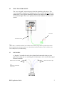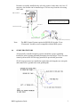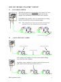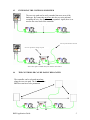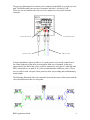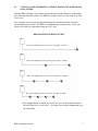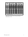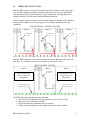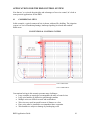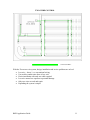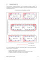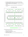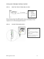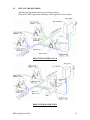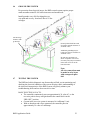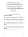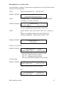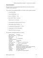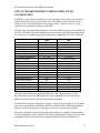
1
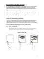
TUCOR RKD CONTROL SYSTEM
In 1995, TUCOR was the first company to bring proven “two-wire” control technology
from Europe to the American landscape irrigation industry. For over ten years now,
Tucor has been developing and introducing new products to satisfy a broad variety of
high-end irrigation control requirements.
Now, with the new Tucor RKD Controller, two-wire control has been simplified. It is
now much easier for contractors who have not made the transition from conventional
control systems to two-wire systems. There is now an opportunity to take advantage of
the many benefits of this technology.
WHAT IS “TWO-WIRE” CONTROL?
“Two-wire” irrigation control is a low-voltage irrigation control system that utilizes a
two-conductor wire to power all of the valves in an irrigation system. All valves are
connected to the same pair of wires, so the need for multiple control wires is eliminated.
There are four major components of a “two-wire” control system:
#1
THE CONTROLLER
The controller (in this case, the RKD) provides the power and programming to
operate the valves. It requires 120 volts AC, like most other controllers.
RKD CONTROLLER
(Door Closed View)
(Door Open View)
(Internal View)
Internal Transformer
120-Volt Power Wire
1
#2
THE “TWO-WIRE PATH”
The “two-wire path” carries the power from the controller to the valves. This
“two-wire path” is simply a two-conductor wire (Tucor #16/2) that all valves are
connected to. Valves can be connected to the two-wire path in series like a string
of ornamental lights. There is no polarity between the conductors in a two-wire
system.
Tucor Wire
120-Volt Power Wire
Note:
“Tucor Wire” is a double-insulated, two-conductor wire made by Paige Electric specifically for Tucor.
Inside a high-density polyethylene jacket are red and black insulated conductors. These conductors are
color-coded for ease of troubleshooting.
#3
DECODERS
A “decoder” is installed at each valve solenoid and connected to the two-wire
path. The decoder acts as a switching device that turns a valve on/off with a signal
from the controller.
Blue wires to two-wire path
White wires to valve solenoid
Note:
Solenoid wire 150 feet max.
with #18 wire.
RKLD-050
DECODER
RKD Application Guide
2
Decoders are usually installed at the valve they control, in the same valve box. If
necessary, the decoder can be installed up to 150 feet away from the valve using
#18/2 wire.
RKD Controller
Note:
Waterproof wire connectors are required!
Tucor Wire
120-Volt Power Wire
RKLD-050 Decoder
Control Valve (24 volt AC)
Note:
#4
The RKD Control System requires the RKLD-050 decoder. Tucor
“Flowmaster" decoders are not compatible with the RKD system.
SURGE PROTECTORS
All electrically controlled irrigation systems should have proper grounding
installed to protect against potentially damaging electrical surges. Tucor two-wire
control systems utilize SP-100 surge protectors to provide this protection.
SP-100 surge protectors are installed at regular intervals along the two-wire path
and connected to a ground rod at each ground point.
RKD Application Guide
3
WHY USE THE RKD “TWO-WIRE” SYSTEM?
#1
LESS WIRE IS NEEDED
The RKD can operate up to one hundred valves from a #16/2 wire.
The decoders along the two-wire path eliminate the need for
multiple wires and multiple station terminals at the controller.
Using RKLD-050 decoders, valves are connected in series along
the two-wire path like a string of ornamental lights.
Note: This system does not require special valves and will work
with most 24-volt AC solenoid valves on the market.
Tucor wire to next valve
#2
VALVES ARE EASILY ADDED
Existing valve & decoder
Existing valve & decoder
Existing two-wire path
Valves can be easily added to a two-wire system without running
new wires back to the controller.
Anywhere a valve is needed, it is simple to splice into the two-wire
path, install a decoder and wire the new valve to it.
RKD Application Guide
4
#3
EXTENDING THE SYSTEM IS SIMPLIFIED
The two-wire path can be easily extended into new areas of the
landscape. By connecting anywhere into the two-wire path and
extending the wire, the system can be expanded. Again, there is no
need to run wires back to the controller.
Existing two-wire path
Two-wire path extended to new area
New wire spliced into existing wire path.
Note: Wire splices should always be made in valve boxes.
#4
THE CONTROLLER CAN BE EASILY RELOCATED
The controller can be relocated anywhere
along the two-wire path. The location of the
RKD does not have to be permanent.
RKD Application Guide
5
The previous illustrations have shown valves connected to the RKD via a single two-wire
path. The RKD actually has two sets of terminals, labeled #1 A-B and #2 A-B.
These two sets of terminals allow the use of two separate two-wire paths from the
controller.
#1 Wire Path Terminals
Green Tucor Wire
#2 Wire Path Terminals
Blue Tucor Wire
In larger installations, where possible, it is a good practice to locate the controller near
the control midpoint of the entire system and use both sets of terminals. In this way,
approximately one-half of the valves would be connected to wire path #1, while the other
half is connected to wire path #2. It is also recommended that a different color of Tucor
wire be used for each wire path. These practices make wire tracking and troubleshooting
much simpler.
The following illustration shows the controller located at the center of the system with the
valves divided between the two wire paths.
RKD Application Guide
6
#5
VALVES CAN BE OPERATED AT GREAT DISTANCES WITH SMALL
GAUGE WIRE
With the RKD, multiple valves can be operated at much greater distances, with smaller
wire, than conventional systems. The RKD can operate valves over one mile away with
#16/2 wire!
Also, multiple valves can be operated simultaneously with much smaller wire than
conventional systems allow. The RKD can simultaneously operate twelve valves, one
master valve and two pump starts using one #16/2 wire.
RKD MAXIMUM WIRE LENGTHS
RKD
Max. wire length with 1 active valve per wire path = 6,200 ft.*
RKD
Max. wire length with 2 active valves per wire path = 5,600 ft.*
RKD
Max. wire length with 3 active valves per wire path = 4,900 ft.*
RKD
Max. wire length with 4 active valves per wire path = 4,300 ft.*
* Wire lengths shown are based on #16/2 Tucor wire, with all the decoders at
the end of the wire (“worse case”). For other, more typical arrangements, see
the chart below.
RKD Application Guide
7
Number of
simultaneous
valves
1
2
3
4
5
6
7
8
9
10
10 + 1 manual
10 + 2 manual
Valves evenly distributed
along 2-wire (ft.)
Worse case: all valves at
end of 2-wire (ft.)
AWG
18
AWG
16
AWG
14
AWG
18
7,000
6,400
5,500
4,900
4,400
4,000
3,600
3,300
3,100
2,800
2,700
2,500
11,000
10,200
8,800
7,800
7,000
6,300
5,800
5,300
4,900
4,600
4,300
4,000
17,800
16,300
14,100
12,500
11,200
10,100
9,200
8,500
7,800
7,300
6,800
6,400
3,900
3,500
3,100
2,700
2,400
2,200
2,000
1,800
1,700
1,600
1,500
1,400
AWG
16
6,200
5,600
4,900
4,300
3,900
3,500
3,200
2,900
2,700
2,500
2,300
2,200
AWG
14
9,900
9,000
7,800
6,900
6,200
5,600
5,100
4,700
4,300
4,000
3,800
3,500
Note: distances given using default valve power settings; if a higher power setting is
used, distances are shorter.
Chart of the maximum distances in feet of the two-wire path (that is, from the
RKD controller to a valve), for a given wire gauge and the number of
simultaneously active valves.
RKD Application Guide
8
#6
REDUCED UTILITY COSTS
With the RKD, many valves can be operated over greater distances with small gauge
wire. In many situations, multiple controllers and power sources can be minimized,
reducing the cost of electrical contractors, utility connections, and ongoing electric
company billings. The following example illustrates this point:
In this example, control valves are spread around a large site. Because of the distances
between valves and the need for large gauge wire, multiple controllers are being
considered.
CONVENTIONAL CONTROL SYSTEM
AREA #1
AREA #2
New Electric
Service
AREA #3
New Electric
Service
New Electric
Service
Electric
Meter
Controller
With the RKD controller, valves can be operated over great distances with #16/2 wire.
Therefore, one controller can be used, saving on electric service costs.
RKD CONTROL SYSTEM
AREA #1
The need for a new
electric service is
eliminated!
Two-wire path replaces
multiple control wires
AREA #2
New Electric
Service
AREA #3
The need for a new
electric service is
eliminated!
Two-wire path replaces
multiple control wires
The RKD offers great advantages in this situation:
ü All valves can be operated from one controller (up to 6,700 feet away)
ü Only one electrical hookup is needed
ü Electrical contractor installation costs are reduced
ü Utility company installation and monthly operating costs are reduced.
RKD Application Guide
9
APPLICATIONS FOR THE RKD CONTROL SYSTEM
Now that we’ve reviewed the principles and advantages of two-wire control, let’s look at
some practical applications for the RKD.
#1
COMMERCIAL SITES
In this example, a typical commercial site is shown with an office building. The irrigation
system is to cover foundation plantings, landscaped parking lot islands and roadside
buffer areas.
CONVENTIONAL CONTROL SYSTEM
#14/1 Control Wire
#12/1 Common Wire
Conventional wiring in this scenario presents many challenges:
• Large conduits are required to accommodate the mass of control wires
• Large wire bundles are difficult to pull through conduits
• Multiple wires are difficult to track and troubleshoot
• Wire sizes may need increased because of distance to valves
• Extra wires must be installed to accommodate future expansion
• Wire bundles are subject to damage by landscaping work
RKD Application Guide
10
TWO-WIRE CONTROL
#16/2 Tucor Wire
With the Tucor two-wire system, design, installation and service problems are solved:
• Less wire – about ¼ vs. conventional wiring
• Use smaller conduit since there is less wire
• Easier installation with only one cable required
• Less wire means less exposure to potential damage
• Only two wires to track and repair
• Expanding the system is simple
RKD Application Guide
11
#2
PHASED PROJECTS
In this example, a multiple building site, such as an apartment complex is shown. The
buildings are constructed in phases as numbered, which presents challenges in design,
installation and service.
CONVENTIONAL CONTROL SYSTEM
#14/1 Control Wire
#12/1 Common Wire
As a result of phased-in construction, each building has its own irrigation controller,
which creates a set of problems:
•
•
•
Each controller requires its own power source.
Multiple controllers in limited-access areas increases service time.
Controller locations are fixed and not easily changed.
RKD Application Guide
12
•
•
•
•
The number of controllers increases service time, even for minor changes.
No coordination between controllers makes it difficult to program within water
windows and conform to local water regulations.
The quantity of buried wire increases the possibilities for damage by landscaping
activities.
As more buildings are constructed in future phases, all control problems are
multiplied.
TWO-WIRE CONTROL
#16/2 Tucor Wire
With the Tucor two-wire system, design, installation and service problems are solved:
• Requires only one controller
• Just one power source required
• Controller access and service time is reduced
• Programming is simplified
• Water window requirements can be met (with sufficient hydraulic capacity)
RKD Application Guide
13
•
•
•
•
•
•
#3
Extending the control system is simple – splice into the two-wire path anywhere
and add valves or extend wire as needed
Adding new buildings to the system is easy
Controller location is not permanent – can be moved anywhere along the two-wire
path
Uses much less wire –about 1/3 as compared to a conventional system
Less buried wire reduces exposure to damage
Troubleshooting two wires is much simpler than conventional wiring
SPORTS FIELD COMPLEX – CONTROL RETROFIT
In this example, several athletic fields have been built over time, each with a separate
controller. Programming has been complicated by insufficient hydraulic capacity.
Scheduling was not coordinated and hydraulic capacity was exceeded resulting in poor
coverage, poor field conditions and excessive water use.
The solution is to retrofit the existing controls with a new two-wire control system that
requires only one controller.
CONVENTIONAL CONTROL SYSTEM
#14/1 Control Wire
#12/1 Common Wire
RKD Application Guide
14
Separate controllers for each field present problems:
• Individual controllers make coordination of programs difficult
• Bad irrigation practices since hydraulic capacity isn’t managed
• Poor irrigation = poor field conditions
• Water use is excessive because of lack of controller coordination (watering time,
rain shut-off, etc.)
TWO-WIRE CONTROL
#16/2 Tucor Wire
With the Tucor two-wire system, irrigation practices are improved and operating costs
are reduced:
•
•
•
•
•
Single controller allows easier programming
Scheduling of water use is now managed
Operating costs reduced: less labor, less water
Easy to extend the system to new fields in the same complex without adding
controllers
Uses 1/5 wire of the conventional system
RKD Application Guide
15
#4
ROADWAY PROJECT
In this example, a highway beautification project requires irrigation for landscaped
medians and roadside buffer areas.
CONVENTIONAL CONTROL SYSTEM
#14/1 Control Wire
#12/1 Common Wire
Long, linear projects such as this present unique challenges:
• Heavy gauge wire (#14, #12, #10 and larger) is needed to overcome voltage loss
over great distances from the controller
• Large conduits are needed for massive wire bundles
• Large wire bundles are difficult to pull through conduits
• Multiple wires are difficult to track and troubleshoot and are subject to damage by
landscaping work
• Extra wires must be installed to accommodate future expansion
TWO-WIRE CONTROL SYSTEM
#16/2 Tucor Wire
RKD Application Guide
16
With the two-wire system, design, installation and service problems are solved:
•
•
•
•
•
Less wire needed – requires approximately ¼ the total wire vs. conventional
control systems
Smaller wire is required – valves can be operated over greater distances with
small gauge wire, like #16/2
Reduced cost of road crossings since smaller conduit can be used
Only one cable needed
o easier installation
o easier tracking & troubleshooting
o less exposure to damage
Easy to extend the system for future phases – simply splice into two-wire path
anywhere and extend
RKD APPLICATIONS:
ü Sports field complexes
ü School districts
ü Municipalities
ü Homeowners associations
ü Real estate developers
ü Nurseries, tree farms, orchards
ü Small agricultural
RKD Application Guide
17
INSTALLING THE RKD CONTROL SYSTEM
STEP #1
SELECTING THE CONTROLLER LOCATION
15 ft. minimum
Electric Motors:
• Pumps
• AC Units
• Compressors
• Refrigerators
• Etc.
When selecting a location for the RKD controller, choose a mounting point at least 15
feet from away from high current drawing electric motors such as pumps, AC units,
compressors, etc. to avoid electromagnetic interference.
STEP #2
CONNECT THE POWER SUPPLY
The RKD has an internal transformer
that requires a 120-volt AC power
supply.
For ease of service, it is best if the
controller is connected to a dedicated
electrical circuit.
All electrical work should be done in
accordance with local codes.
RKD Application Guide
18
STEP #3
CONNECTING THE TWO-WIRE PATH
There are two sets of terminals for the twowire path: #1 and #2.
It is recommended that both wire paths be
used, dividing the valves between them.
This makes future trouble-shooting easier.
The wire paths can also be split at the
controller to further divide the system. All
splices should be made in weatherproof
junction boxes as shown.
IF THE WIRE PATHS MUST BE
SPLIT BELOW THE GROUND, ALL
WIRE SPLICES MUST BE MADE
WITH TUCOR WATERPROOF
SPLICE KITS IN EASILY
ACCESSIBLE VALVE BOXES!
Note:
Tucor wire has red and black insulation on
the two conductors for easier
identification. The two-wire path is not
polarized.
RKD Application Guide
19
STEP #4
PROGRAM THE DECODERS
Program the decoders to the
desired station number. Don’t
forget to label the decoders as
you program or re-program
them.
Decoder programming can be
done at the controller or in the
field using the HCP-100.
Important:
Decoders can be reprogrammed
to new station numbers. There
is no limit on the number of
times a decoder can be reprogrammed.
RKD Application Guide
20
#5
INSTALL THE DECODERS
The following illustrations show typical wiring scenarios.
Refer to the “RKD Application Drawings” in the appendix for more details.
RKD WITH MASTER VALVE
RKD WITH BOOSTER PUMP
RKD Application Guide
21
Note: The decoder can supply about 100 ma of continuous current to a motor relay.
If the pump start relay requires more than this, an intermediate low-power
(“ice cube”) relay will be required.
Note: All wire connections must be made in valve boxes with waterproof splice kits!
Installation Tips:
•
•
•
•
•
•
•
•
•
•
DO NOT ATTACH MORE THAN ONE VALVE TO A DECODER!
Use caution when stripping insulation from the Tucor wire. Nicks in wire and
insulation can lead to problems.
Lightly score the outer jacket, bend and pull off exposing the two inner
conductors.
Strip insulation from the black and red conductors.
Be careful not to score the copper wire when stripping insulation.
Use the waterproof wire splices that are shipped with the decoders.
Make all splices in valve boxes
Mark the location of all decoders, splices and surge protectors on the plans.
Leave 12" of wire coiled at all splices for easier servicing.
Keep splices upright and high in the valve box to avoid submersion.
RKD Application Guide
22
#6
GROUND THE SYSTEM
For protection from electrical surges, the RKD control system requires proper
earth grounding using SP-100 surge protectors and ground rods.
Install grounds every 600 feet along the twowire path and at every “dead end” that is 25 feet
or longer.
SP-100 Surge
Protector with
ground rod
Ground points should be tested
for earth-to-ground resistance of
50 Ohms or less.
Additional grounding may be
required to decrease resistance to
50 Ohms or less.
SP-100 surge protectors are
shown in separate valve boxes
for clarity. They may be installed
in the same valve box as the
nearest decoder.
Note:
All wire connections must
be made in valve boxes
with waterproof splice
kits!
#7
TESTING THE SYSTEM
The RKD has built-in diagnostic test features that will aid you in monitoring and
checking the electrical condition of the system. Having a basic understanding of
the electrical characteristics of the RKD system will greatly enhance your
troubleshooting skills and cut down on service time.
BASIC ELECTRICAL FACTS:
• The controller continuously puts out approximately 36 volts AC, so the
two-wire path is always energized unless the control dial is in the
“IRR. OFF” position.
• Current in the two-wire system is measured in “milliamps” (ma).
• With no decoders and valves connected, the controller puts out
approximately 36 volts at 2 milliamps.
RKD Application Guide
23
•
•
•
•
•
When connected to the two-wire path, each decoder draws approximately
0.5 milliamps in “standby” mode, i.e., no valves open.
As decoders are connected to the system, the standby current draw
increases by approximately 0.5 milliamps per decoder.
Theoretically, an RKD controller with sixty decoders attached should
draw approximately 32 milliamps. (60 decoders x 0.5mA + 2ma for the
controller)
Full load output from the controller is approximately 600-700ma.
When a single valve solenoid is energized, the current draw is
approximately 40 - 50 milliamps (depending on the solenoid’s
characteristics). Multiple valves operating simultaneously will draw more
current as follows:
1 valve = 40 - 50 ma
2 valves = 80 - 100 ma
3 valves = 120 - 150 ma
4 valves = 160 - 200 ma
...
10 valves = 400 – 500 ma
Note: Master valve and pump start current not included.
CHECKING LINE CONDITION
LineV/MA values referred to in this section are enabled under “Advanced Setup”
options; see your User’s Manual. When enabled, the time-of-day is not displayed on the
screen.
Steady, alternating red and green LED’s indicates normal line condition. With no active
valves, the line display should read approximately 36 volts / x ma (ma will depend on the
“x” number of decoders connected to the system; see “Basic Electrical Facts” above).
Hesitating red and green flashing LED’s indicate a problem in the two-wire path. Check
the #1 wire path by disconnecting the #2 line, and vice-versa, to isolate the faulty wire.
(But also note that the LED’s will quickly flash for a few seconds from time to time, as,
for instance, when valves are turned on or off. This is normal communications on the
two-wire.)
If the LED’s are not lit, with power on, this indicates a dead short in the two-wire path.
In this state, the line display will read less than 22V and 150 - 200mA. If so, check for
crossed wires or physical damage to the two-wire path. Disconnecting the two-wire path
at the controller should cause the LED’s to flash as normal. This confirms a two-wire
path problem.
Line condition is also tested when performing a “Station Test”.
RKD Application Guide
24
PERFORMING A STATION TEST
Once installation is complete, a simple station test should be run. This will check decoder
and valve electrical operation.
USER:
SET DIAL POSITION TO: “SETUP/TEST”
DISPLAY SHOWS:
USER:
** Setup and Test Functions **
Choose action from buttons below.
PUSH BUTTON:
“WATER BUDGET / STATION TEST”
(Red light next to button will flash)
DISPLAY SHOWS:
Start from:
** Station Test **
ST1
Line: 36v/ X m
[X varies, depending upon total decoders connected.]
USER:
PUSH “ENTER / YES” BUTTON TO TEST “ST1” (Station #1)
or
SELECT ANOTHER STATION TO TEST WITH THE
UP/DOWN ARROWS…THEN PUSH “ENTER / YES”
DISPLAY SHOWS:
** Testing Station ST1 **
Please Wait!
If the test was successful:
DISPLAY SHOWS:
** Test of Station ST1
Station: 656ma/ 53ma
***OK***
Line: 36v/ Xm
Station readings indicate normal current situation.
The “656” = Inrush current to solenoid
The “53” = Holding current to solenoid
Your values may differ, depending on the solenoid.
If the test failed:
DISPLAY SHOWS:
** Test of Station ST1
Station: 664ma/ 9ma
!!! FAILED !!!
Line: 36v/ Xma
Station readings indicate a short at solenoid.
OR
** Test of Station ST1
Station: 12ma/ 12ma
RKD Application Guide
!!! FAILED !!!
Line: 36v/ Xma
25
Station readings indicate an open (i.e., broken wire) at solenoid.
PROGRAMMING
Once the decoders have been programmed and installed and each station tested, the
controller can be programmed.
The procedure for programming the RKD is very similar to other irrigation controllers:
1. Set DATE & TIME
2. Select a PROGRAM (1 – 4)
3. Select a STATION (1 – 100)
4. Enter a RUN TIME (0 – 999 min.)
Repeat Step #4 for each station
5. Select program WATER DAYS (S-M-T-W, etc.)
6. Enter program START TIMES (1 – 6)
7. Set program WATER BUDGET (0 – 250%)
8. Set program as ACTIVE OR PASSIVE
9. Repeat steps for the next program.
The capabilities of the RKD controller are as follows:
Station Capacity:
100 valves
Max. Active Valves: 4 + 1 Master Valve
Master Valves:
1
Pump Starts:
2
Programs:
4 + 1 test program
Concurrent Programs: 4
Start Times:
6 per program
Calendar:
14 days
Station Run Times:
0 – 999 min. in 1 min. increments
Water Budget:
0 – 250% in 1 min. increments
Program Modes:
Active & Passive
Start Methods:
Auto, Manual by program or station
Display:
Monitors active programs, run times and line condition
Decoders:
Programmable and testable at the controller
Diagnostics:
Decoder pass/fail, short test
Terminals:
Rain sensor, alarm, ET
Serial Port:
PC connection for firmware updates
RKD Application Guide
26
For advanced features, see the RKD User Manual.
HOW IS THE RKD DIFFERENT FROM OTHER TUCOR
CONTROLLERS?
The RKD was developed to simplify two-wire technology and to make it economically
feasible for smaller scale projects of up to 100 valves. Many of the advanced features
found in Tucor’s Flowmaster Series of controllers (TWC, Com, ProCom, etc.) were
eliminated or scaled down in design of the RKD.
The following comparison chart illustrates some of the differences between the RKD and
the TWC controller. This chart should help you in deciding if the RKD is the right choice
for your project, or perhaps you will need the greater capabilities of the TWC controller.
Valve Capacity
Simultaneous Valves
Master valve/pump start
Booster pumps
User Interface
Upgradeable capacity
Max. Programs (Schedules)
Programming Method
Valve sequence
Rain Sensor Input
ET capable
Flow sensors
Alarm & React to Flow
Remote Software
On-Line Monitoring
Data Logging & Reports
Communication Options
Decoder
Decoder Test
Short Circuit Test
Upgradeable Firmware
RKD
TWC
100
50/100/200
4
10
1
1
2
9
Dial & button
Dial & button or remote software
No
Yes
4 + 1 test
10 + 1 test
Programs & Stations
Schedules & Steps
Fixed sequence 1 thru 100 Sequence is programmable
Yes
Yes
Yes
Yes
N/A
10
N/A
Yes
N/A
Yes
N/A
Yes
N/A
Yes
N/A
Yes
Programmable
Non-programmable
Yes
Yes
Yes
Yes
Yes
Yes
The other major difference between the RKD and TWC control systems is in the
decoders that are used. The RKD controller requires the RKLD-050 decoder that is
different from those used with Tucor Flowmaster controllers.
The RKLD-050 decoder is designed to operate a single valve per station. It was designed
to be user-programmable at the RKD controller or with the HCP-100 hand programmer.
The user can easily program (or re-program) a decoder to operate a given station.
Flowmaster decoders are available in single and multiple valve models. These decoders
are not programmable at the controller but can be reprogrammed with the HCP-100 hand
programmer. Flowmaster decoders are shipped with predetermined identification
RKD Application Guide
27
numbers (addresses). These addresses must be associated with valve locations and
entered into the controller database. It is the ability to create this database that gives the
Flowmaster controllers powerful operating flexibility. Most notably, the user can
program the sequence that valves turn on/off by schedule (program).
The RKD controller uses a much simpler operating arrangement than the Flowmaster
controllers and decoders. Valves turn on/off in sequence (1 through 100) just like a
conventional controller.
The RKD will only operate with the RKLD-050 decoder. This decoder is a single-valve,
programmable decoder that is shipped in a “blank” state without any programming. Since
the RKD uses the concept of “stations” instead of “addresses” (as in the Flowmaster),
programming is very easy for a newcomer to two-wire control systems.
This decoder can be programmed with a station number (1 through 100) right at the
controller by connecting it to the designated terminals and following the on screen steps.
The decoder is labeled as station #_____ and wired to the valve where you want that
station number. If you want to change the station number for a valve, you can re-program
the decoder to the station number that you want.
An optional handheld decoder programming unit is available for programming or reprogramming decoders in the field.
RKD Application Guide
28
APPENDIX
A
RKD Application Guide
29
RKD Application Guide
30
RKD Application Guide
31
RKD Application Guide
32
RKD Application Guide
33
RKD Application Guide
34
RKD Application Guide
35
RKD Application Guide
36
RKD Application Guide
37
APPENDIX
B
RKD Application Guide
38
TUCOR RKD CONTROL SYSTEM SPECIFICATIONS
The Automatic Irrigation System Controls shall be the RKD Control System as
manufactured by Tucor, Inc. of Wexford, Pennsylvania and hereinafter specified.
The RKD Control System shall be comprised of the Tucor RKD Controller, RKLD050
Programmable Decoders, Tucor #16/2 Communication Cable, Tucor SP-100 Line Surge
Protectors, Tucor HCP-100 Portable Decoder Programmer (Optional) and all other
equipment required for a complete system.
RKD CONTROLLER
The Tucor RKD Controller shall be a standalone controller capable of operating one
hundred 24VAC solenoid valves along a two-wire path. The controller shall be capable of
simultaneously operating four valves, one master valve and two booster pumps from the
two-wire path. The controller shall be capable of operating a single valve connected to
the two-wire path up to 6,100 feet away using #16/2 Tucor communication cable.
The RKD shall have a locking metal NEMA-rated cabinet with internal transformer
requiring 120 VAC electrical input and 24 VAC output. Two-wire path output from the
controller shall be 34 VAC. The controller shall have built-in lightning protection.
The RKD shall have four independent programs plus one test program. Programs shall
run concurrently with six start times per program over a fourteen-day calendar. Station
run times shall be adjustable from 0-999 minutes in one-minute increments. Stations will
operate in sequence from 1 – 100. The controller shall have a water budget feature that
will adjust the water budget of each program independently from 0-250% in one percent
increments. Programs shall have both active and passive modes.
The controller shall have the capability to start programs and stations automatically or
manually. Manual start of programs and/or stations shall be accomplished without the
need to pause or cancel currently running programs.
The RKD shall have a backlit display with brightness adjustment. The display shall be
capable of showing the operating status of the system. Active programs, run times and the
current time shall be displayed. The controller shall have an option to monitor and
display the electrical conditions of the two-wire path including current (in milliamps) and
voltage.
The controller shall have built in diagnostics that will test for station individual station
operation, decoder pass/fail and electrical shorts in the two-wire path.
The RKD shall be capable of operating two booster pumps. Booster operation shall be
assignable to individual programs. Valve output power shall be adjustable through menu
options that allow for four different power levels.
The controller shall have separate terminals for connection to a rain sensor, alarm and ET
input. ET input shall be provided by an optional WR-7 or WR-100i weather sensor.
RKD Application Guide
39
The controller shall include a special circuit for monitoring, on a continuous basis, the
line voltage condition. In the event of an electrical short, the controller will automatically
switch to 50Hz mode at reduced current.
The controller shall also have terminals for connection of decoders for the purpose of
programming, reprogramming and testing decoders.
The optional HCP-100 hand programmer shall have the same decoder programming
capabilities as the RKD50 controller.
Install the RKD controller in accordance with local electrical codes and with a proper
electrical ground. The controller should be mounted in an easily accessible location and
at a height that allows convenient operation of controls.
LINE DECODERS
RKLD50 decoders shall provide the interface between the 24 VAC valves and the twowire communication from the RKD controller.
RKLD50 decoders shall be shipped in a “blank” state with no programming information.
For programming, decoders shall be connected to the RKD controller decoder terminals
and programmed with the desired station address. Decoders shall be programmable as
station numbers one through one hundred (“ST1” through “ST00”), master valve (“MV),
booster pump #1 (“BO1”) or booster pump #2 (“BO2”). Decoders shall have the ability
to be reprogrammed to other station addresses. The controller shall have a decoder test
function that will give a decoder pass/fail test result.
Each decoder shall be epoxy sealed and completely waterproof. Each decoder shall have
“built-in” surge protection as an integral part of the basic decoder.
The decoder shall have two (2) blue colored wires for connection to the two-wire path
communication path and two (2) white colored wires for connection to the valve solenoid
wires.
Each decoder shall be labeled with the station address that was programmed into it. A
programmed decoder shall be installed with the valve that corresponds to the
programmed station number. In most cases, the decoder shall be installed in the same
valve box as the valve it operates. For remote installation, the decoder to valve distance
shall not exceed 150 feet using #14 wire.
Decoder out put shall be 24 VAC. Each RKLD50 decoder shall be capable of operating
one valve solenoid.
THE LOCATION OF EACH DECODER SHALL BE MARKED ON THE AS-BUILT
PLANS.
RKD Application Guide
40
TWO-WIRE PATH
All wire used for communication between the RKD controller and the RKLD50 decoders
shall be double-jacketed, two (2) conductor cable specifically designed by Paige Electric
for use with Tucor control systems. The cable shall be suitable for direct burial, or for
installation in ducts or conduits.
The conductors shall be #16 AWG tin-coated, soft drawn, annealed, solid copper
conforming to ASTM 33 with 4/64” thick PVC (polyvinyl chloride) insulation,
conforming to UL Standard #493 for thermoplastic insulated style UF (Underground
Feeder), rated at 60 degrees C.
The two insulated conductors shall be laid parallel and encased in a single outer jacket of
3/64” thick, high density, sunlight resistant polyethylene conforming to ICEA S-61-402
and NEMA WC5, having a minimum wall thickness of .045”. The outer jacket shall be
pressure extruded so as to completely fill the interstices between the two insulated wires,
or may have tube jacketing or form an envelope over the two insulated UF conductors
lying in parallel at the discretion of the manufacturer.
The two conductors shall be color coded with one conductor black and the other red.
Both conductors shall be the SAME SIZE.
All splices and connections in this wiring shall be made using the waterproof splice
connectors provided with the RKLD50 decoder. 3M DBY wire connector kits may also
be used. Any other type of wire connector will NOT be accepted. Care shall be taken
with each wire connection to assure a tight, waterproof connection. IT IS ESSENTIAL
THAT ALL CONNECTIONS BE ABSOLUTELY WATERTIGHT WITH NO
LEAKAGE TO GROUND NOR SHORTING BETWEEN CONDUCTORS.
SURGE PROTECTION
All surge protection, grounding and installation of equipment specified, shall be installed
in strict compliance with the manufacturer’s recommendations and in accordance with
Local, State and Federal requirements.
Primary Power Surge Protection:
Furnish and install surge protection on the power circuit that will supply power to the
controller.
Field Surge Protection:
SP-100 surge protectors shall be installed at every line termination point. Additional SP100’s shall be installed at every 600-foot interval along the two-wire path, located at the
nearest line decoder. Connect SP-100 ground wires to a single 8-foot ground rod. If the
valve is metallic or the solenoid has a metallic center pin, one of the SP-100 ground wires
shall be connected to it.
RKD Application Guide
41
All SP-100/ground rod assemblies shall be installed in valve boxes. Mark the location of
all ground points on the as-built plans.
All grounds shall be tested for earth-to-ground resistance. Readings of 50 Ohms or less
are acceptable. Resistance readings of 50 Ohms or greater shall necessitate the
installation of additional grounding materials to reduce the ground resistance to
acceptable levels.
RKD Application Guide
42