1
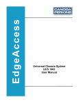
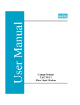
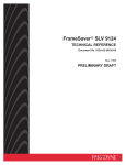
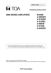
Model 9120
Gigabit Ethernet Media
Converter
User Manual
Canoga Perkins
CAUTION!
This product may contain a laser diode operating at a wavelength of 1300nm - 1600nm. Use of
optical instruments (e.g., collimating optics) with this product may increase eye hazard. Use of
controls or adjustments, or performing procedures other than those specified herein may result in
hazardous radiation exposure.
Under normal conditions, the radiation levels emitted by this product are under Class 1 limits in 21
CFR Chapter 1, Subchapter J.
ATTENCION!
Cet équipement peut avoir une diode laser émettant à des longueurs d'onde allant de 1300nm à
1600nm. L'utilisation d'instruments optiques (par exemple : un collimateur optique) avec cet
équipement peut s'avèrer dangereuse pour les yeux. Procéder à des contrôles, des ajustements ou toute
procédure autre que celles décrites ci-après peut provoquer une exposition dangereuse à des
radiations.
Sous des conditions normales, le niveau des radiations émises par cet équipement est en dessous des
limites prescrites dans CFR21, chapitre 1, sous chapitre J.
NOTICE!
This device contains static sensitive components. It should be handled only with proper ElectroStatic
Discharge (ESD) grounding procedures.
NOTE!
Cet équipement contient des composants sensibles aux décharges électro-statiques. Il doit absolument
être manipulé en respectant les règles de mise à la terre afin de prévenir de telles décharges.
ii
9120 Gigabit Ethernet Media Converter
Canoga Perkins
NOTICE
Canoga Perkins has prepared this users manual for use by customers and Canoga Perkins personnel as
a guide for the proper installation, operation and/or maintenance of Canoga Perkins equipment. The
drawings, specifications and information contained in this document are the property of Canoga
Perkins and any unauthorized use or disclosure of such drawings, specifications and information is
prohibited.
Canoga Perkins reserves the right to change or update the contents of this manual and to change the
specifications of its products at any time without prior notification. Every effort has been made to
keep the information in this document current and accurate as of the date of publication or revision.
However, no guarantee is given or implied that the document is error free or that is accurate with
regard to any specification.
Canoga Perkins Corporation
20600 Prairie Street
Chatsworth, California 91311-6008
Business Phone: (818) 718-6300
(Monday - Friday 7 a.m. - 5 p.m. Pacific Time)
FAX: (818) 718-6312 (24hrs.)
Web Site: www.canoga.com
Email: [email protected]
Copyright© 2001 - 2005 Canoga Perkins Corporation
All Rights Reserved
Model 9120 Gigabit Media Converter
User Manual
Product Number 6911750
Rev. H 09/2005
To reference Technical Advisories and Product Release Notes, go to Canoga Perkins'
website: http://www.canoga.com/cservice.htm
9120 Gigabit Ethernet Media Converter
iii
Canoga Perkins
Table of Contents
Chapter 1 Overview..................................................................................................1-1
1.1
1.2
Ship List ..................................................................................................................................1-2
Applications ............................................................................................................................1-2
Chapter 2 Setup and Installation ............................................................................2-1
2.1
Unpacking ...............................................................................................................................2-1
2.2
Setup of the 9120 Media Converter ........................................................................................2-1
2.2.1 User Port Connection .............................................................................................................2-1
2.2.2 Extension Port Connection.....................................................................................................2-2
2.2.3 Four-Position DIP Switch ......................................................................................................2-2
2.3
Installing the 9120 Media Converter.......................................................................................2-3
2.3.1 Standalone Unit ......................................................................................................................2-3
2.3.2 Rackmount Installation ..........................................................................................................2-3
2.3.3 Configuring the Fault/Forwarding DIP Switch ......................................................................2-4
Chapter 3 Operation.................................................................................................3-1
3.1
LED Indicators ........................................................................................................................3-1
3.2.1 Canoga Remote Fault .............................................................................................................3-2
3.2.2 Link Loss Forwarding - User to Extension ............................................................................3-3
3.2.3 Link Loss Forwarding - Extension to User ............................................................................3-4
3.2.4 Link Loss Echo ......................................................................................................................3-5
3.3
Models and Product Description .............................................................................................3-7
Chapter 4 Troubleshooting ......................................................................................4-1
Chapter 5 Technical Specifications .........................................................................5-1
5.1
5.2
5.3
5.4
5.5
5.6
5.7
Gigabit Multimode (MM) 850nm (SX)...................................................................................5-1
Gigabit Single Mode (SM) 1310nm LX..................................................................................5-1
Gigabit Single Mode (SM) 1310nm LD (DFB) ......................................................................5-2
Gigabit Single Mode (SM) 1550nm EX (DFB) ......................................................................5-2
Functional................................................................................................................................5-3
Power.......................................................................................................................................5-3
Physical / Environmental ........................................................................................................5-3
Chapter 6 Glossary ...................................................................................................6-1
Appendix A ............................................................................................................... A-1
iv
9120 Gigabit Ethernet Media Converter
Canoga Perkins
List of Figures
Figure 1. 9120 Categories................................................................................................................. 1-1
Figure 2. Typical 9120 Application................................................................................................... 1-2
Figure 3. 9120 Extended Application. ............................................................................................... 1-3
Figure 4. Front View of the 9120. ..................................................................................................... 2-1
Figure 5. User Port............................................................................................................................ 2-2
Figure 6. Extension Port.................................................................................................................... 2-2
Figure 7. Four Position DIP Switch.................................................................................................. 2-2
Figure 9. 9101 LAN Chassis with 9120's. ......................................................................................... 2-3
Figure 10. Fault Forwarding DIP Switch. ........................................................................................ 2-4
Figure 11. LED Indicators. ............................................................................................................... 3-1
Figure 12. Remote Fault Diagram. ................................................................................................... 3-2
Figure 13. Link Loss Forwarding - User to Extension...................................................................... 3-3
Figure 14. Link Loss Forwarding - Extension to User...................................................................... 3-4
Figure 15. Link Loss Echo Switch Position....................................................................................... 3-5
Figure 16. Link Loss Enable fault with 9120 to 9120 Link. .............................................................. 3-5
Figure 17. Link Loss Enable fault with 9120 to Customer Premise Link.......................................... 3-6
List of Tables
Table 1. LED Descriptions. ............................................................................................................... 3-1
9120 Gigabit Ethernet Media Converter
v
Canoga Perkins
This page is intentionally left blank.
vi
9120 Gigabit Ethernet Media Converter
Canoga Perkins
Chapter 1
Overview
The 9120 is a Gigabit Ethernet Media Converter. It extends multi mode Gigabit segments up to 70km
over single mode fiber. It is designed for installation into the Canoga Perkins 9101 Chassis and is also
available as a standalone unit. The unit is especially suited for the long-distance extension of Gigabit
LAN segments. Extension port options include 1310nm on multimode or single mode fiber and
1550nm on singlemode fiber.
The 9120 introduces Gigabit extension capability to Canoga Perkins 9101 chassis. It is field
installable and can coexist with Canoga Perkins 8829 10Mbps, and 9119 100Mbps Ethernet
converters. The 9120 is a NEBS Level 3 compliant (in chassis) product designed and built with
quality components to ensure reliability and longevity.
The 9120 features user controllable Link Loss Forwarding (LLF), Canoga Remote Fault (RMTF), and
Link Loss Echo (LLE). The user may enable or disable these features from a set of easily accessed
switches located on the front panel of the 9120. Primary application is the interconnection of gigabit
Enterprise Switches and Service Provider Backbone Networks. Within the 9101 platform, the 9120
addresses the Service Providers' requirements for Transparent LAN Services across a widely
dispersed customer environment and physical plant.
The 9120 Media Converter is available in three categories:
•
•
•
Gigabit Ethernet 850nm
Gigabit Ethernet 1310nm
Gigabit Ethernet 1550nm
MM
SM
SM
SC
SC
SC
Figure 1. 9120 Categories.
9120 Gigabit Ethernet Media Converter
1-1
Canoga Perkins
9120 Media Converter Feature List:
•
•
•
•
•
•
•
•
•
Full-duplex 1000Mbps Ethernet operation up to 70km
Multimode and single mode fiber support
Supports 850nm, 1310nm and 1550nm
Field installable into existing 9101 Chassis
Available as standalone or rackmount for EdgeAccess 9101Chassis
Front panel LEDs for diagnostics and monitoring
Link Loss Forwarding, Canoga Remote Fault, and Link Loss Echo Alarms
User Configurable Link Loss Forwarding, Canoga Remote Fault, and Link Loss Echo
NEBS Level 3 compliant (in the 9101 Chassis)
1.1
Ship List
The following items are included:
•
•
•
•
9120 Media Converter
User Manual
Power Supply with 6-foot power cord (standalone model only)
Tie Wrap/Velcro Kit
1.2
Applications
Figure 2 shows a typical application allowing a full-duplex link at a distance of up to 70km.
Figure 2. Typical 9120 Application.
1-2
9120 Gigabit Ethernet Media Converter
Canoga Perkins
Figure 3. 9120 Extended Application.
9120 Gigabit Ethernet Media Converter
1-3
Canoga Perkins
This page is intentionally left blank.
1-4
9120 Gigabit Ethernet Media Converter
Canoga Perkins
Chapter 2
Setup and Installation
This section details the unpacking, setup, and the options for installing the 9120 Media Converter.
Figure 4 shows the front view of the 9120 Media Converter.
Figure 4. Front View of the 9120.
2.1
Unpacking
Canoga Perkins products are carefully inspected and tested prior to shipment from the factory. It is
recommended that you keep the shipping package until the unit has been installed and verified as
being fully operational. In the unlikely event that the unit is defective, contact the Canoga Perkins
Customer Service department for a Return Material Authorization (RMA) number. For directions on
how to return the unit, refer to Appendix A.
Canoga Perkins products, like all electronic devices with static sensitive components, should be
handled with care. Since there are no user-serviceable parts inside the unit, opening the case will void
the factory warranty.
2.2
Setup of the 9120 Media Converter
The 9120 Gigabit Media Converter standalone model requires its own power source. The desktop
version of the 9120 Media Converter is supplied with a wall-mount power supply that requires 100240VAC at 50-60Hz and provides +5VDC to the unit. The unit can be rack mounted in the 9101
LAN Chassis. The 9120 Gigabit Media Converter rackmounted model is powered by the 9101 LAN
Chassis.
2.2.1 User Port Connection
The 9120 Media Converter features a Duplex SC multimode or single mode fiber optical connector
on the user side of the network, located on the front of the unit (Reference Figure 4). The user port is
angled to facilitate decreased fiber bend when the 9120 is mounted vertically in a 9101 chassis.
9120 Gigabit Ethernet Media Converter
2-1
Canoga Perkins
Figure 5. User Port.
2.2.2 Extension Port Connection
The 9120 Media Converter features a Duplex SC single mode fiber optical connector on the extension
side of the network, located on the rear of the unit (Reference Figure 5).
Figure 6. Extension Port.
Note: When working with fiber optic cables and connectors, care should be taken to prevent
contaminating connector plugs and sleeves. Dirt and dust can significantly affect connector insertion
loss and consequently degrade performance.
2.2.3 Four-Position DIP Switch
Link Loss Forwarding and Canoga Remote Fault features are configured with a 4-position DIP switch
located on the front of the unit (Reference Figure 6).
Figure 7. Four Position DIP Switch.
2-2
9120 Gigabit Ethernet Media Converter
Canoga Perkins
2.3
Installing the 9120 Media Converter
The 9120 Media Converter can be easily installed in the Canoga Perkins Model 9101 LAN Chassis,
attached to vertical or horizontal surfaces, or used in a tabletop configuration. As with all electronic
devices, adequate air flow should be provided around the unit since some heat is generated.
The 9120 should not be placed on top of another device that also generates heat. The cumulative heat
can cause the internal temperature of the 9120 to exceed its design specifications which could
potentially lead to inconsistent operation.
2.3.1 Standalone Unit
In addition to being placed on a desktop, the 9120 standalone can be attached to the side of any
surface (PC, cabinet, desk, etc.). An attachment kit is shipped with the 9120 standalone unit for this
purpose.
Wherever the unit is mounted, the decision for the location will include determining a mounting place
for a transformer as well. The power supply is furnished with a 6-foot power cord. The connector for
the power supply is located on the rear panel of the unit.
2.3.2 Rackmount Installation
Up to twelve 9120 Media Converters can be inserted into a Canoga Perkins Model 9101 LAN Chassis
for high-density installation (see Figure 8).
Figure 9. 9101 LAN Chassis with 9120's.
9120 Gigabit Ethernet Media Converter
2-3
Canoga Perkins
2.3.3 Configuring the Fault/Forwarding DIP Switch
The 9120 includes a four-position DIP switch that must be configured for correct Link Loss and
Canoga Remote Fault routing. This switch is on the front of the unit (Reference Figure 9):
Figure 10. Fault Forwarding DIP Switch.
From left to right, the switch configuration is:
RMTF (Remote Fault):
Canoga-specific Remote Fault feature (Extension Port Only).
Enable = On
Disable = Off
This feature is used typically when two 9120’s are connected in
series. LLE must be disabled for this feature to be active.
LLF (Link Loss Forward):
Enables or Disables Link Loss Forwarding.
Enable = On
Disable = Off
The direction of fault propagation is determined by the DIR switch
setting.
DIR (LLF Direction):
If LLF is ON, the DIR switch controls the direction of error
propagation.
DIR ON = Extension to User OFF = User to Extension
If LLF is OFF, switch is ignored.
LLE: (Link Loss Echo):
Link-down propagation to non-Canoga connected devices (Extension
Port Only).
Enable = On / Disable = Off.
If a link down is encountered on the Extension port, the Tx
Extension port will be disabled. Link Loss Echo configures the 9120
to not send data until data is received. Therefore, Link Loss Echo
should not be used in series with another 9120 that has LLE
enabled.
Note: LLE cannot be used in conjunction with RMTF.
2-4
9120 Gigabit Ethernet Media Converter
Canoga Perkins
Chapter 3
Operation
3.1
LED Indicators
The 9120 Media Converter has eight LED indicators on the front panel (Reference Figure 10).
Figure 11. LED Indicators.
LED Indicator
PWR
LNK
Rx
Tx
RMTF
LNK
Rx
Tx
Table 1. LED Descriptions.
Description
Power Indicator - when illuminated green, the 9120 is receiving power.
Extension Port LED Indicators
Extension Port Link - illuminates green when the Extension Port link is good.
When the LED is off, the link is bad. *
Receive data - when illuminated green, the Extension Port is receiving data. ***
Transmit data - when illuminated green, the Extension Port is transmitting data.
When illuminated red, the Extension Port transmitter is is not transmitting (may
be shut down as in a LLF condition). ***
Remote Fault - This function applies only to the extension port. Upon loss of link
on the extension port, the remote device transmits an RMTF pulse from its Tx
port (the RMTF LED illuminates red on the local device) to the local device
indicating its link loss condition. **
User Port LED Indicators
User Port Link - illuminates green when the User Port link is good. When the
LED is off, the link is bad.
Receive data - when illuminated green, the User Port is receiving data. ***
Transmit data - when illuminated green, the User Port is transmitting data. When
illuminated red, the User Port transmitter is is not transmitting (may be shut
down as in a LLF condition). ***
*
When the LNK LED on the Extension Port is off a RMTF signal is forwarded to the remote unit and via a LLF signal
will disable its Extension Port transmitter causing a loss of link integrity at the local device.
**
Upon receipt of the RMTF signal, the local unit will illuminate the RMTF indicator and invoke LLF on the local
interface if LLF is enabled and the direction is set to Extension Port to User Port.
*** The 9120 is a transparent device which will detect the presence of any type of packets, data or otherwise, coming
across the data link. This feature may cause the Rx and Tx indicators to illuminate green when data packets are not
transmitted, yet other monitoring information is (e.g., auto negotiation - if this feature is enabled on the equipment
interfacing with the 9120, the Rx and Tx indicators will illuminate green, even when data packets are not transmitted).
9120 Gigabit Ethernet Media Converter
3-1
Canoga Perkins
3.2.1 Canoga Remote Fault
The remote fault function applies to Extension Port only. If the extension port lost link, the media
converter will transmit a Canoga-specific Remote Fault pattern to Extension Port's transmitter.
In the diagram below, when a unit detects a link loss on the Extension Rx port, a Remote Fault pattern
will be sent to the remote unit. The unit that detected the link loss will display a red RMTF LED.
Note the DIP switch RMTF setting must be enabled (up) to activate the RMTF functionality.
Figure 12. Remote Fault Diagram.
3-2
9120 Gigabit Ethernet Media Converter
Canoga Perkins
3.2.2 Link Loss Forwarding - User to Extension
When a loss of signal is detected is detected on the User Rx port, the fault is propagated to the
Extension port. The Extension Tx LED will display red, indicating the propagation of the fault to the
Extension port. The fault is then propagated to the remote link.
Note: The DIP switch Link Loss Forwarding feature must be enabled (up) and the Direction switch
set to "User to Extension (down)."
Extension
Port
Figure 13. Link Loss Forwarding - User to Extension.
9120 Gigabit Ethernet Media Converter
3-3
Canoga Perkins
3.2.3 Link Loss Forwarding - Extension to User
When a loss of signal is detected on the Extension Port Rx, the fault is propagated to the User Port.
The User Port Tx LED will display red, indicating the propagation of the fault to the User Port. The
fault is then propagated to the remote link.
Note: The DIP switch Link Loss Forwarding feature must be enabled (up) and the Direction switch
set to "Extension to User (up)."
Extension
Port
Figure 14. Link Loss Forwarding - Extension to User.
3-4
9120 Gigabit Ethernet Media Converter
Canoga Perkins
3.2.4 Link Loss Echo
Link Loss Echo is the Link-down propagation to another connected device (9120 or non-Canoga
equipment). Link Loss Echo will work only on the Extension Port. If a link loss is detected on the
Extension Port Rx, the Extension Port Tx will be disabled, echoing the fault back to the source. Link
Loss Echo configures the 9120 to not send data until data is received.
Figure 15. Link Loss Echo Switch Position.
9120 Linked to a 9120
When a 9120, linked to another 9120, detects a loss of signal on the User Port Rx, it will stop
transmitting to the remote 9120. Two 9120s cannot be linked together with Link Loss Echo enabled
on both units.
Extension
Port
Extension
Port
Figure 16. Link Loss Enable fault with 9120 to 9120 Link.
9120 Gigabit Ethernet Media Converter
3-5
Canoga Perkins
9120 Linked to Customer Equipment
When the 9120, linked to customer equipment, detects a loss of signal on the Extension Port Rx, the
9120 will stop transmitting to the customer equipment.
Extension
Port
Graphics Legend
Figure 17. Link Loss Enable fault with 9120 to Customer Premise Link.
3-6
9120 Gigabit Ethernet Media Converter
Canoga Perkins
3.3
Models and Product Description
Model
Extension Port Description
User Port: 1000BASE-SX, 850nm, MM, SC, 5.5dB, Full-duplex
9120-528-1-0 1000BASE-LX, 1310nm, SM, SC, 7dB, Full-duplex
for use in the 9101 powered LAN Chassis
9120-528-1-1 1000BASE-LX, SM, SC, 7dB, Full-duplex
120/240 VAC AC Adapter
User Port: 1000BASE-SX, 850nm,MM, SC, 5.5dB, Full-duplex
9120-628-1-0 1000BASE-LD, 1310nm Extended Distance DFB laser, SM, SC, 21dB, Full-duplex
for use in the 9101 powered LAN Chassis
9120-628-1-1 1000BASE-LD, 1310nm Extended Distance DFB laser, SM, SC, 21dB, Full-duplex
120/240 VAC AC Adapter
User Port: 1000BASE-SX, 850nm, MM, SC, 5.5dB, Full-duplex
9120-728-1-0 1000BASE-EX, 1550nm Extended Distance DFB laser, SM, SC, 21dB, Full-duplex
for use in the 9101 LAN Chassis
9120-728-1-1 1000BASE-FX, 1550nm Extended Distance DFB laser, SM, SC, 21dB, Full-duplex
120/240VAC AC Adapter
User Port: 1000BASE-LX, 1310nm, SM, SC, 7dB, Full-duplex
9120-828-1-0 1000BASE-EX, 1550nm Extended Distance DFB laser, SM, SC, 21dB, Full-duplex
for use in the 9101 LAN Chassis
9120-828-1-1 1000BASE-EX, 1550nm Extended Distance DFB laser, SM, SC, 21dB, Full-duplex
120/240VAC AC Adapter
Note: Typically the loss budgets are 2dB greater than listed.
9120 Gigabit Ethernet Media Converter
3-7
Canoga Perkins
This page is intentionally left blank.
3-8
9120 Gigabit Ethernet Media Converter
Canoga Perkins
Chapter 4
Troubleshooting
In the case of the 9120 Media Converter, a hybrid device, there are two LNK LED indicators, marked
User LNK and Extension LNK. When the 9120 Media Converter is put into service, if all cables are
correctly connected and there are User and Extension devices attached to the cable, both LNK
indicators should illuminate. If either LNK Indicator does not illuminate, check the appropriate
attached cable and remote transmitter to ensure they are connected properly.
This implies that if the LNK indicator is illuminated on the local device, the remote transmitter, the
attached cable and the local receiver are operational. Thus, if the RMTF LED indicator is
illuminated, it indicates a problem with either the local fiber transmitter, the attached cable, or the
remote fiber receiver.
The 9120 Media Converter's Link Loss Forwarding (LLF) feature will disable the Extension or User
transmitter whenever the Extension LNK LED indicator is off. This allows the fiber failure to be
sensed by a management agent at the remote User port as a User Link failure. Therefore, whenever
the User transmitter appears to be off, check the receive Extension link cable connections to the 9120
media converter and ensure the F/LNK LED indicator is illuminated.
If the Power LED indicator and both LNK indicators are illuminated, and the RMTF indicator is off,
you can assume with some assurance that the problem exists elsewhere. Data transfer through the
9120 Media Converter can only take place when both LNK indicators are illuminated and the RMTF
indicator is off. The most common cause of network problems, once physical layer problems are
resolved, is software configurations.
In addition, check that the total link loss is within the allowable fiber optic loss budget, and that the
proposed application is within normal IEEE 802.3 Propagation Delay Budget.
If this still does not solve the problem, call the Canoga Perkins Service Department at (818) 7186300.
9120 Gigabit Ethernet Media Converter
4-1
Canoga Perkins
This page is intentionally left blank.
4-2
9120 Gigabit Ethernet Media Converter
Canoga Perkins
Chapter 5
Technical Specifications
5.1
Gigabit Multimode (MM) 850nm (SX)
Emitter Type:
VCEL
Wavelength:
850nm nominal
Transmit Launch Power:
-4.0 dBm maximum
-9.5 dBm minimum
Receive Sensitivity:
-15dBm minimum
Overdrive:
-3.0dBm
Loss Budget:
5.5dB minimum
Optical Connector:
Duplex SC
5.2
Gigabit Single Mode (SM) 1310nm LX
Emitter Type:
Laser Diode
Wavelength:
1310nm nominal
Transmit Launch Power:
-3.0 dBm maximum
-11.0 dBm minimum
Receive Sensitivity:
-18dBm minimum
Overdrive:
-3.0 dBm maximum
Loss Budget:
7.0 dB minimum
Optical Connector:
Duplex SC
9120 Gigabit Ethernet Media Converter
5-1
Canoga Perkins
5.3
Gigabit Single Mode (SM) 1310nm LD (DFB)
Emitter Type:
Laser Diode
Wavelength:
1310nm nominal
Transmit Power:
+2.0 dBm maximum
0.0 dBm minimum
Receive Sensitivity:
-21.0 dBm Maximum
Overdrive:
-3dBm maximum
Loss Budget:
21dB minimum
Optical Connector:
Duplex SC
5.4
Gigabit Single Mode (SM) 1550nm EX (DFB)
Emitter Type:
Laser Diode
Wavelength:
1550nm nominal
Transmit Power:
+2.0 dBm maximum
0 dBm minimum
Receive Sensitivity:
-23.0 dBm minimum
Overdrive:
-3dBm maximum
Loss Budget:
23 dB minimum
Optical Connector:
Duplex SC
5-2
9120 Gigabit Ethernet Media Converter
Canoga Perkins
5.5
Functional
Data Interface:
ISO/IEC 8802.3
Gigabit
Fiber:
Duplex SC per ANSI X3.237-1995
Average One-way Latency:
60nsec, max.
5.6
Power
Standalone:
120/240VAC, 50/60Hz, 10W Max
Rackmount:
5W Max.
5.7
Physical / Environmental
Enclosure:
Standalone Metal Housing
Dimensions:
1.1"H x 3.4"W x 6.0"D
Weight:
Approximately 9 oz. (0.25kg)
Power Supply:
Standalone
External Wall Mount Type
• Dimensions: 3"L x 2"W x 1.6"D
• Power Cord: 6 feet
Operating Temperature:
0° - 50°C
Humidity:
up to 90% (noncondensing)
Regulatory Compliance:
UL 1950/CSA C22.2 No. 950
IEC 60950
IEC 825-1
FCC Part 15 Class A/IC CS-003
EN 300386-2 (in 9101 Chassis)
AS/NZS 3548
NEBS Level 3 (in 9101 Chassis)
9120 Gigabit Ethernet Media Converter
5-3
Canoga Perkins
This page is intentionally left blank.
\
5-4
9120 Gigabit Ethernet Media Converter
Canoga Perkins
Chapter 6
Glossary
CSMA/CD
Carrier Sense Multiple Access with Collision Detection
FDDI
Fiber Distribution Data Interface
FDX
Full-Duplex
LED
Light Emitting Diode
NEBS
Network Equipment Building Systems
NIC
Network Interface Card
nm
nanometer
SMF/PMD
Single-Mode Fiber / Physical Media Dependent
9120 Gigabit Ethernet Media Converter
6-1
Canoga Perkins
This page is intentionally left blank.
6-2
9120 Gigabit Ethernet Media Converter
Canoga Perkins
Appendix A Warranty
Limited Lifetime Warranty
Effective July 1, 2005 and After, Canoga Perkins warrants that, at the time of sale, and, for its lifetime,
with certain exceptions noted below, every Canoga Perkins' labeled product purchased will be free from
defects in material and workmanship for its lifetime, if properly installed and used in conformity to Canoga
Perkins' published specifications. This warranty covers the original user only and is not transferable. For
the purposes of this Warranty, "lifetime" is defined as the serviceable life of the product (a minimum of 5
years) or any longer period during which replacement spare parts are available. Subject to the conditions
and limitations set forth below, Canoga Perkins will, at its option, either repair or replace any part of its
product(s) that prove defective by reason of improper workmanship or materials. The warranty period for
power supplies, fans and optics is five (5) years. Consumables such as filters are covered for one year.
Software is warranted for 90 days. Hardened Media Converter (HS) products are covered for three (3)
years.
This warranty does not cover any damage to products that have been subjected to lightning or other Acts of
Nature, misuse, neglect, accident, damage, improper installation, or maintenance, including over-voltage
failures caused by use outside of the product's specified rating, normal wear and tear of mechanical
components, or alteration or repair by anyone other than Canoga Perkins or its authorized representative. If
the user is unsure about the proper means of installing or using the equipment, contact Canoga Perkins' free
technical support services. Customer must notify Canoga Perkins promptly in writing of any claim based
on warranty. Canoga Perkins is not liable for, and does not cover under warranty, any costs associated with
servicing and/or the installation of its products or for any inspection, packing or labor costs in connection
with return of goods. In the event Canoga Perkins breaches its obligation of warranty, customer's sole and
exclusive remedy is limited to replacement, repair, or credit of the purchase price, at Canoga Perkins'
option. Under no circumstance will Canoga Perkins be liable for consequential or incidental damages or
loss of profits.
Warranty Registration
To establish original ownership and to record purchase date, please complete the warranty on-line form on
our product registration page. URL: www.canoga.com/warranty
Optional Service Programs
Canoga Perkins offers several optional Service Programs. Please call Canoga Perkins Sales Department
(818-718-6300) or see our web site (www.canoga.com) for details.
CUSTOMER SERVICE DEPARTMENT REPAIR WARRANTY
Repairs performed by the Canoga Perkins Customer Service Department will be free from defects in
material and workmanship for a period of ninety (90) DAYS from the date the repaired product is shipped,
or until the expiration of the original factory warranty, whichever is longer.
9120 Gigabit Ethernet Media Converter
A-1
Canoga Perkins
Limitations
Canoga Perkins may at its sole discretion modify its Limited Warranty at any time and from time to time.
Other than those expressly stated herein, THERE ARE NO OTHER WARRANTIES OF ANY KIND,
EXPRESSED OR IMPLIED, AND SPECIFICALLY EXCLUDED BUT NOT BY WAY OF
LIMITATION, ARE THE IMPLIED WARRANTIES FOR FITNESS FOR A PARTICULAR PURPOSE
AND MERCHANTABILITY. IT IS UNDERSTOOD AND AGREED CANOGA PERKINS' LIABILITY
WHETHER IN CONTRACT, IN TORT, UNDER ANY WARRANTY, IN NEGLIGENCE OR
OTHERWISE SHALL NOT EXCEED THE AMOUNT OF THE PURCHASE PRICE PAID BY THE
CUSTOMER AND UNDER NO CIRCUMSTANCES SHALL CANOGA PERKINS BE LIABLE FOR
SPECIAL, INDIRECT, INCIDENTAL OR CONSEQUENTIAL DAMAGES. THE PRICE STATED FOR
THE EQUIPMENT IS A CONSIDERATION IN LIMITING CANOGA PERKINS' LIABILITY. NO
ACTION, REGARDLESS OF FORM, ARISING OUT OF THE TRANSACTIONS OF THIS
AGREEMENT MAY BE BROUGHT BY CUSTOMER MORE THAN ONE YEAR AFTER THE
CAUSE OF THE ACTION HAS ACCRUED. CANOGA PERKINS' MAXIMUM LIABILITY SHALL
NOT EXCEED AND CUSTOMER'S REMEDY IS LIMITED TO EITHER (i) REPAIR OR
REPLACEMENT OF THE DEFECTIVE PART OF PRODUCT, OR AT CANOGA PERKINS' OPTION
(ii) RETURN OF THE PRODUCT AND REFUND OF THE PURCHASE PRICE, AND SUCH REMEDY
SHALL BE CUSTOMER'S ENTIRE AND EXCLUSIVE REMEDY. AUTHORIZED RESELLERS ARE
NOT AUTHORIZED TO EXTEND ANY DIFFERENT WARRANTY ON CANOGA PERKINS'
BEHALF.
Return Policy
Customer must obtain an RMA (Return Material Authorization) number from the Canoga Perkins
Customer Service Department before returning a product for service or repair.
Canoga Perkins' technical support department can be reached through any of the following means:
Telephone: 818-718-6300
Fax: 818-718-6312
E-Mail: [email protected]
If the warranty for a power supply, fan, optics, consumable or software has expired, customer must provide
the Canoga Perkins Customer Service Representative with a Purchase Order to authorize the repair.
Send the defective product postage and insurance prepaid to the address provided to you by Canoga
Perkins' technical support representative. Failure to properly protect the product during shipping may void
this warranty. The return authorization number must be written on the outside of the carton to ensure its
acceptance.
The customer must pay for the non-compliant product(s) return transportation costs to Canoga Perkins for
evaluation of said product(s) for repair or replacement. Canoga Perkins will pay for the shipping of the
repaired or replaced in-warranty product(s) back to the customer (any and all customs charges, tariffs,
or/and taxes are the customer's responsibility).
Canoga Perkins reserves the right to charge for all testing and shipping incurred, if after testing, a return is
classified as "No Problem Found."
A-2
9120 Gigabit Ethernet Media Converter
CANOGA PERKINS CORPORATION
20600 Prairie Street
Chatsworth, California 91311-6008 USA
Phone: (818) 718-6300 FAX: (818) 718-6312
Web Site: www.canoga.com
Email: [email protected]