1
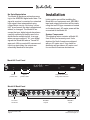
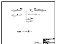
Model 85 AES/EBU Digital
Audio Distribution Amplifier
User Guide
Issue 3, November 1999
This User Guide is applicable for serial numbers:
Model 85 M85-00151 and later
Copyright © 1999 by Studio Technologies, Inc., all rights reserved
5520 West Touhy Avenue
Skokie, Illinois 60077 U.S.A.
Telephone (847) 676-9177
Fax (847) 982-0747
www.studio-tech.com
50211-1199, Issue 3
Table of Contents
Foreword ...................................................................... 5
Introduction .................................................................. 7
What This User Guide Covers ..................................... 7
System Overview ......................................................... 7
Installation .................................................................... 8
Configuration ............................................................... 10
Operation ..................................................................... 10
Troubleshooting ........................................................... 10
Specifications ............................................................... 12
Block Diagram
Model 85 User Guide
Studio Technologies, Inc.
Issue 3, November 1999
Page 3
This page intentionally left blank.
Issue 3, November 1999
Page 4
Model 85 User Guide
Studio Technologies, Inc.
Foreword
As both president and owner of Studio Technologies, I take a very personal approach
when designing products. Do the technical and operational aspects of a product work
together to “feel” right? Is the product something I'd like to use in my own studio? A new
product from Studio Technologies is ready to go only when I am completely satisfied.
With that in mind, I am sincerely pleased to present the Model 85 AES/EBU Digital Audio
Distribution Amplifier.
Many fine people worked toward making the Model 85 “happen.” Mitch Budniak (ace
consulting engineer) designed the circuitry. Carrie Loving provided engineering support.
Ben Kamen designed the automatic testing routines. Al Lux designed the printed circuit
board. Fred Roeck performed the mechanical design. Joe Urbanczyk coordinated the
safety testing and agency approvals.
I'm always receptive to your comments and questions. Please contact me via phone
(847) 676-9177, fax at (847) 982-0747, or the Internet @ www.studio-tech.com.
Sincerely,
Gordon K. Kapes
President
Model 85 User Guide
Studio Technologies, Inc.
Issue 3, November 1999
Page 5
This page intentionally left blank.
Issue 3, November 1999
Page 6
Model 85 User Guide
Studio Technologies, Inc.
Introduction
The Model 85 AES/EBU Digital Audio
Distribution Amplifier is designed by Studio
Technologies as part of its Studio Tools
group of audio support products.
Designed for a wide variety of recording,
production, broadcast, and duplication
applications, the Model 85 has two
AES/EBU inputs and eight AES/EBU
outputs. All Model 85 functions meet or
exceed the performance of the most
expensive “high end” audio equipment.
What This User Guide Covers
This User Guide is designed to assist
you when installing, configuring, and
using the Model 85 AES/EBU Digital
Audio Distribution Amplifier.
System Overview
The Model 85 provides two AES/EBU
digital audio inputs and eight AES/EBU
outputs. Each of the eight outputs provides
a fully isolated reproduction of either input.
Output source selection is provided by
front-panel DIP switches. The Model 85
allows AES/EBU signals to be distributed
to multiple inputs (receivers) without incurring data transmission errors.
A typical application would use the Model
85 to distribute the AES/EBU output of a
digital audio workstation (DAW) to devices
such as DAT or CD recorders, audio/video
storage systems, tie lines to other facilities, etc.
Single rack space mounting, standard
XLR-type connectors, and status LEDs
make installation of the Model 85 a simple
Model 85 User Guide
Studio Technologies, Inc.
job. The AC mains input power is factory
configured for 100, 120, or 220/240V
operation. Components and construction
standards make the Model 85 suitable for
continuous operation, even for on-air
broadcast applications.
AES/EBU Inputs
Each of the two inputs have transformer
coupling and DC voltage blocking. An LED
status indicator is associated with each
input, lighting whenever digital information
is present.
AES/EBU Outputs
The Model 85 contains eight independent
AES/EBU output sections. The rugged
output circuits feature transformer coupling. For flexibility, each of the eight
outputs can individually select input A or
B as its source. This allows the Model 85
to act as a single 1x8 distribution amplifier
(DA), or two fully independent DAs.
Example configurations include creating
a dual 1x4 DA, or a combination 1x3 DA
and 1x5 DA.
Technical Background
The original AES/EBU specification
(AES3-1985) called for a single transmitter
to drive up to three receivers. In practice
this proved to make data transmission
susceptible to errors as an impedance
mismatch is created whenever more than
one receiver is driven. The revised edition
of the specification (AES3-1992) advises
that a single transmitter should drive only
a single receiver. The Model 85 addresses
this requirement in a simple, reliable
manner. Up to eight identical, but fully
isolated, “copies” of the original source
are created.
Issue 3, November 1999
Page 7
No Data Manipulation
The Model 85 performs minimal processing to the AES/EBU digital audio data. The
signal is received, converted to a standard
logic signal, then retransmitted using
rugged driver circuits. No timing “correction” is performed. No data is manipulated,
added, or changed. The Model 85 assumes that your digital signals have been
carefully created and simply need to be
distributed to multiple inputs. In an age
when everyone wants to “fix” your digital
signals the Model 85 takes a “hands off”
approach. With a nominal 60 nanosecond
input to output delay, the outputs are
essentially identical to the inputs.
Installation
In this section you will be installing the
Model 85 in an equipment rack. AES/EBU
input and output connections will be made
using the ten XLR-type connectors located
on the back panel. AC mains power will be
connected to the Model 85.
System Components
The shipping carton contains a Model 85,
User Guide, and warranty card. Units
destined for North America are shipped
with an AC mains cord. Your dealer or
distributor will provide an AC mains cord
for non-North American destinations.
Model 85 Front Panel
AES/EBU DIGITAL AUDIO DISTRIBUTION AMPLIFIER
OUTPUT SELECT
INPUT A
POWER
INPUT B
INPUT A
1 2 3 4 5 6 7 8
INPUT B
SKOKIE, ILLINOIS U.S.A.
SIGNAL PRESENT
Power
present LED
Signal
present LEDs
Output source select
configuration switches
Model 85 Back Panel
AC mains
connection
Issue 3, November 1999
Page 8
AES/EBU
outputs
AES/EBU
inputs
Model 85 User Guide
Studio Technologies, Inc.
Mounting the Model 85
The Model 85 requires one space in a
standard 19-inch (48.3cm) equipment
rack. It is desirable to locate the Model 85
to allow easy access to both the front and
the back panels. The back panel contains
the input and output connectors. The front
panel is used to access the output-select
switches. The front panel also contains
several LED indicators. The Model 85 is
secured to the equipment rack using two
mounting screws per side.
AES/EBU Inputs
The Model 85 provides two AES/EBU
inputs. Physically the inputs are located on
the back panel and use standard 3-pin
XLR-type female connectors. The source
signals will need to terminate on cables
with XLR-type male plugs to connect with
the inputs.
While it’s a good idea to always maintain
consistent cable polarity, the AES/EBU
specification clearly states that signal
polarity is not an issue. With this in mind
understand that identifying one of the pins
as “hot” or “high” is not really relevant. For
consistency the Model 85 does maintain
input-to-output polarity. A low-to-high
transition on pin 2 of the input results in
a low-to-high transition on an output.
For best performance you should consider
AES/EBU signals to always be a balanced
(differential) signal. Pins 2 and 3 of the
XLR-type connectors should carry signal
and pin 1 is appropriate for shield. Never
strap pin 2 or pin 3 to pin 1—this might be
appropriate for unbalanced analog signals
but not for this fast-movin’ digital cat!
Beyond containing a shield appropriate for
digital signals, the exact cable choice is up
to you. There is an inverse relationship
Model 85 User Guide
Studio Technologies, Inc.
between cable capacitance and maximum
allowable cable length. The AES/EBU
specification calls for a 100 meter maximum, but high performance cable should
allow a longer run.
Part of the Model 85’s flexibility is the fact
that each of the eight outputs can select
as its source either input A or input B. If
you’re using the unit strictly as a 1-input/
8-output device, only a connection to input
A is required. If some outputs have input
A as their source, and others have input
B as their source, then you’ll need signals
connected to both inputs.
AES/EBU Outputs
The Model 85 contains eight independent
AES/EBU outputs. The signals are accessible on the back panel by means of eight
3-pin XLR-type male connectors. Your
cables will need to terminate on XLR-type
female connectors. The recommendations
made for the inputs also apply for the
outputs: maintain polarity, wire for balanced operation, and select, if appropriate,
a low-capacitance cable.
AC Mains Power
The Model 85 is internally configured to
operate from either 100, 120, or 220/240V,
50/60Hz. In most cases, units shipped to
North America are factory selected for
120V operation. Units bound for Japan are
selected for 100V, while our friends “down
under” and in Europe receive units set for
220/240V. Before connecting the Model 85
to AC mains power, check that it is configured to match the local mains voltage.
Look on the back panel, adjacent to the
power entry connector, for the configured
voltage(s). Note than an incorrect configuration could seriously damage the unit.
Should it be necessary to change the
Issue 3, November 1999
Page 9
unit’s operating voltage it must be performed only at the factory or by an authorized service technician.
The Model 85 uses an IEC standard
connector to mate with the AC mains cord.
The wire colors in the AC mains cord
should conform to the internationally
recognized CEE color code and must
be wired accordingly:
Connection
Wire Color
Neutral (N)
Line (L)
Protective Earth (E)
Light Blue
Brown
Green/Yellow
Safety Warning: The Model 85 does
not contain an AC mains disconnect
switch. As such the mains cord plug
serves as the disconnection device.
Safety consideration requires that
the plug and associated outlet be
easily accessible to allow rapid disconnection of mains power should it prove
necessary.
for each output. The legend on the
switches corresponds to the output channel numbers. A switch that is set to the up
position sets its associated output channel
for a source of input A. A switch in the
down position selects input B. A small flatblade screwdriver may be of assistance
when setting the switches.
Operation
Now that you’ve installed and configured
the system, you’re ready to go. You should
find operation very easy; there is almost
nothing to do on a day-to-day basis. For
peace of mind, the signal present LEDs
will give you a visual indication whenever
signals are present on the Model 85’s
inputs. Note that the signal present LEDs
are not intended to provide an indication
that valid AES/EBU signals are present.
They are provided as a handy macro
method of determining if signals are
active on the inputs.
As soon as AC mains power is connected,
the Model 85’s power present LED will
light. If a digital signal is active on an input
its associated signal present LED will light.
The unit is now ready for years of trusty
service!
Each of the eight outputs is fully independent. You can patch, reconnect, or even
short out an interconnecting cable without
effecting the other outputs. Using the frontpanel DIP switches you can change the
output source of any or all of the outputs
whenever you wish.
Configuration
Troubleshooting
Output Source Selection
If you’re having problems getting the
Model 85 up and running, this section
can help. If you haven’t read the other
sections of this guide, you should do so
before proceeding.
Each of the eight AES/EBU outputs is
individually configurable to have input A
or input B as its source. Eight DIP-type
switches, located on the right side of the
front panel, are used to select the source
Issue 3, November 1999
Page 10
Model 85 User Guide
Studio Technologies, Inc.
If the Model 85 Doesn’t Work At All
A source of AC mains power must be
connected to the Model 85. Depending on
the version you have purchased, 100, 120,
or 220/240Vac, 50/60Hz is required.
Confirm what mains voltage is required by
observing the selection boxes to the left
of the AC mains connector on the back
panel. Whenever mains power is connected the power present LED should be
lit. If the LED is not lit confirm that the
main power source is active (“hot”) and
that the connector on the cord is securely
mated with the plug on the back panel.
For safety in the event of a major internal
failure or the connection of incorrect AC
mains voltage, the Model 85 contains a
fuse inside the cabinet. The fuse will open
(“blow”) if the failure of an internal component causes excessive current to be drawn
from the internal power supply. The fuse
will also open should 220/240Vac be
connected to a Model 85 that is configured
for 100 or 120Vac operation. The fuse is
intended to be replaced only by a qualified
service technician. This person will have
the training to safely access the “guts” of
the Model 85 and identify where a problem
is located.
If Signal Doesn’t Seem to Be Present
on the Outputs
Valid outputs depend on a valid input
source. Ensure that the signal present
LEDs are lit in response to what you
consider valid input signals. Should a
signal present LED not be lit confirm that
the source is operating and the cabling
has been correctly prepared. On the front
panel, check the output source selection
switches to confirm the correct settings.
Model 85 User Guide
Studio Technologies, Inc.
Issue 3, November 1999
Page 11
Specifications
AES/EBU Inputs: 2
Connectors:
Type: capacitor isolated, transformer coupled
AES/EBU: 3-pin XLR-type, female (2), male (8)
Receiver Equalization: none
Impedance: 110 ohms, nominal
AC Mains: standard 3-blade plug, meets IEC 320
specifications
Amplitude Range: 0.3 to 7 Vp-p
AC Mains Requirement:
AES/EBU Outputs: 8
100, 120, or 220/240V, ±10%, factory configured,
50/60Hz, 100-120V 0.4A maximum, 220/240V
0.2A maximum
Type: transformer coupled
Impedance: 110 ohms, nominal
Level: 4.5 Vp-p, terminated, nominal
Input-Output Time Delay: 60nSec, nominal
AES/EBU Performance Compatibility:
Designed for compliance with AES3-1992 (ANSI
S4.40-1992), AES Recommended practice for
digital audio engineering—Serial transmission
format for two-channel linearly represented digital
audio data
Dimensions (Overall):
19.00 inches wide (48.3cm)
1.72 inches high (4.4cm)
6.65 inches deep (16.9cm)
Mounting: one standard rack space
Weight:
7.0 pounds (3.2kg)
LED Indicators: 3
Function: 1 power present, 2 signal present
Fusing: 1
Type: 5 x 20mm time lag (Littelfuse 218-series
or equivalent)
Specifications and information contained in this
User Guide subject to change without notice.
Rating: 0.400A for 100 and 120V mains power,
0.200A for 220/240V mains power
Issue 3, November 1999
Page 12
Model 85 User Guide
Studio Technologies, Inc.