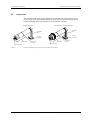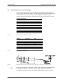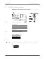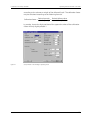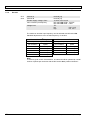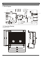
1
Operating manual for micro annular gear pump mzr-2542 / mzr-2942 HNP Mikrosysteme GmbH Bleicherufer 25 D-19053 Schwerin (Germany) Telephone: +49 385/52190-301 Telefax: +49 385/52190-333 E-mail: [email protected] http://www.hnp-mikrosysteme.de Last update: June 2013 Impressum Original instructions Copyright HNP Mikrosysteme GmbH Bleicherufer 25 D-19053 Schwerin All rights, including translation, reserved. Without prior explicit written permission of HNP Mikrosysteme GmbH no part of this manual may be, copied, reproduced or processed. This manual has been prepared with care. HNP Mikrosysteme does assume no liability for any errors in this manual and resulting consequences. Likewise, no liability is assumed direct or subsequent damages arising from an incorrect use of the devices. While using micro annular gear pumps, the relevant standards regarding the specifications of this manual have to be followed. Subject to change without notice. - Operating manual mzr-2542 / mzr 2942 Contents Contents 1 1.1 1.2 1.3 1.4 1.5 General Information Use Pump Model Designation Measurements Flow charts Technical data of the micro annular gear pump mzr-2542 / mzr-2942 Technical data of the motor 1 1 2 2 3 7 7 7 7 8 2.7 2.8 Safety instructions Safety symbols in this operating manual Staff qualification and training Safety-conscious work Safety instructions for the operator Safety instructions for maintenance, check and assembly of the pump Unauthorized pump conversions and spare part manufacture Improper modes of operation General safety instructions 3 3.1 3.2 3.3 Transport and intermediate storage Shipment of the pumps and protection measures Transport Intermediate storage 10 10 10 10 4 4.1 4.2 4.3 4.4 Description of the pump Principle of the Micro annular gear pumps Construction Materials and liquids Fluidic connectors 11 11 13 14 15 5 5.1 5.2 5.3 5.4 5.5 Optional modules Gear box module (optional) Motor with 18 VDC voltage (optional) Drive with a high resolution encoder (optional) Brushless DC motor as drive (option) Brushless DC motor with high torque as drive (option) 17 18 19 20 21 5.6 5.7 Drive with high torque (optional) Drive with DC-Tachogenerator (optional) 22 23 25 6 6.1 6.2 6.3 Mounting/Installation Checkup before the first assembly Mounting of the micro annular gear pump Assembly instruction for tubing and accessories 27 27 27 28 1.6 2 2.1 2.2 2.3 2.4 2.5 2.6 Last update: June 2013 4 5 8 8 9 9 i - Operating manual mzr-2542 / mzr 2942 Contents 6.4 6.5 6.6 6.7 6.8 Filter selection and use Operation with the S-ND control unit Operation with the S-KD control unit (optional) Operation with the S-KG control unit (optional) Operation with the S-BL control unit (optional) 29 30 34 38 41 7 7.1 7.2 7.3 7.4 7.4.1 7.4.2 7.5 7.6 The startup/shutdown of a pump Preparing for operation Startup of the micro annular gear pump Flushing procedure after use Shutdown of the micro annular gear pump Conservation Dismantling of the system Problem shooting Return of the micro annular gear pump to the manufacturer 44 44 44 44 47 49 50 51 8 Software »mzr-Pump controller« 52 9 9.1 9.2 9.3 Software »Motion Manager« (optional) Direct drive control Programming of the control unit Transfer of mcl-files to motor controller 55 55 57 57 10 Accessories for microfluidic systems 60 11 Non-liability clause 60 12 Electromagnetic compatibility (EMC) 60 13 Problem shooting 61 14 14.1 14.1.1 14.1.2 EC Directive Electromagnetic Compatibility (EMC) EMC Directive and Standards Information on use as intended 64 65 65 66 15 Declarations of conformity 67 16 Service, maintenance and warranty 73 17 Contact person 74 18 Legal information 75 19 Safety information for the return of already employed micro annular gear pumps and components General information 76 76 19.1 ii Technical data subject to change without prior notice! 51 Last update: June 2013 - Operating manual mzr-2542 / mzr 2942 Contents 19.2 19.3 20 21 Last update: June 2013 Declaration of media in contact with the micro annular gear pump Shipment 76 76 Declaration of media in contact with the micro annular gear pump and its components. 77 Supplement 78 iii - 1 General Information 1 Operating manual mzr-2542 / mzr 2942 General Information This operation manual contains basic instructions to be followed during integration, operation and maintenance of the mzr® micro annular gear pump. For this reason it is necessary to read it carefully before any handling of the device. The present manual should always be kept at the operation site of the micro annular gear pump. In case assistance is needed, please indicate the pump type visible on the housing. 1.1 Use The micro annular gear pumps mzr-2542 and mzr-2942 described in this manual are suitable for continuous delivery and discrete dosage of water, watery solutions, solvents, methanol, oils, lubricating liquids, paints and varnishes as well as many other liquids. ! If you intend to handle any aggressive, poisonous or radioactive liquids, you must conform to safety measures as according to the regulations in force. Any project concerning handling of corrosive liquids should be previously discussed with the pump manufacturer. ! The micro annular gear pumps should not be used for "invasive" medical applications, in which the liquid having had contact with the pump is reintroduced to the body. ! Micro annular gear pumps exclusively are provided for use in the industrial area. A private use is excluded. ! The micro annular gear pumps must not be used in aircrafts and spacecrafts or other vehicles without prior consent of the manufacturer. ! The data concerning resistance of the pumps to manipulated liquids is elaborated according to the best of HNP Mikrosysteme's knowledge. However, operating parameters varying from one application case to another, no warranty for this information can be given. ! The information given in this manual does not release the customer from personal obligation to check the integrity, correct choice and suitability of the pump for the intended use. The use of the micro annular gear pumps should be conform with technical norms and regulations in force. If you wish to receive more information than comprised in this manual please contact directly HNP Mikrosysteme. Last update: June 2013 Technical data subject to change without prior notice! 1 - 1 General Information 1.2 Operating manual mzr-2542 / mzr 2942 Pump Model Designation This manual is valid for the micro annular gear pumps mzr-2542 and mzr-2942 manufactured by HNP Mikrosysteme GmbH, Bleicherufer 25, D-19053 Schwerin, Germany. The bottom line of this manual shows issue and date of issue of the manual. 1.3 Measurements The micro annular gear pumps mzr-2542 and mzr-2942 have the same outer measurements. The pumps are available in two versions featuring different liquid connectors. figure 1 shows the version with Ø 2 mm slip fittings on which flexible tubes with internal diameter < 2 mm are stuck. figure 2 shows the version with a manifold assembly, which is screwed and fixed with a holding nut to a preadapted support. +0,05 2,3 ±0,05 0,091 ±0,002 Position of this flats not defined +0,002 150 ±5 5,906 ±0,197 2 0,079 16 0,63 18 0,709 2,3 ±0,05 0,091 ±0,002 Orientation of ribbon cable not defined 4 -0,10 0,157 -0,004 7 0,272 83,1 ±0,5 3,272 ±0,020 Ribbon cable AWG 28 DIN Connector 41651 Dimensions are millimeters next to [inches]. figure 1 Measures of the micro annular gear pump mzr-2542 and mzr-2942, configuration with slip fittings OD 2 mm 32 1,26 25 0,984 2,3 ±0,05 0,091 ±0,002 2 ±0,2 0,079 ±0,008 85 ±1,5 3,347 ±0,059 Orientation of ribbon cable not defined Ribbon cable AWG 28 DIN Connector 41651 18 0,709 2,6 ±0,03 0,102 ±0,001 1,9 0,075 Position of this flats not defined 150 ±5 5,906 ±0,197 1,5 0,059 14,5 0,571 1,5x1 (2x) 25 0,984 16 0,63 19 0,748 1,5 0,059 -0,004 -0,1 3,4 0,134 2x O-ring 9 -0,3 0,354 -0,012 2,3 ±0,05 0,091 ±0,002 Dimensions are millimeters next to [inches]. figure 2 2 Measures of the micro annular gear pump mzr-2542 and mzr-2942, configuration with manifold assembly M2.1 Technical data subject to change without prior notice! Last update: June 2013 - 1 General Information 1.4 Operating manual mzr-2542 / mzr 2942 Flow charts Liquid water Liquid oil 10 10 Liquid water Liquid oil Viscosity 16 mPas Viscosity 1 mPas 8 6 Speed [rpm] 4 6000 5000 4000 3000 2000 1000 2 0 0 0,5 1 Flow rate [ml/min] Flow rate [ml/min] 8 6 Speed [rpm] 4 6000 5000 4000 3000 2000 1000 2 0 0 1,5 figure 3 0,5 1 1,5 Differential pressure [bar] Differential pressure [bar] Flow charts of mzr-2542 Liquid water Liquid oil 20 20 Liquid water Liquid oil Viscosity 16 mPas 15 10 Speed [rpm] 6000 5000 4000 3000 2000 1000 5 0 0 1 2 Differential pressure [bar] figure 4 Last update: June 2013 3 Flow rate [ml/min] Flow rate [ml/min] Viscosity 1 mPas 15 10 Speed [rpm] 6000 5000 4000 3000 2000 1000 5 0 0 1 2 3 Differential pressure [bar] Flow charts of mzr-2942 Technical data subject to change without prior notice! 3 - 1 General Information 1.5 Operating manual mzr-2542 / mzr 2942 Technical data of the micro annular gear pump mzr-2542 / mzr-2942 mzr-2542 mzr-2942 Displacement volume 1.5 μl 3 μl Housing length without fluid connections 68 mm 68 mm Housing length with fluid connections slip fitting version Ø 2 mm manifold assembly version 90 mm 87 mm 90 mm 87 mm Diameter 16 mm 16 mm Weight slip fitting version Ø 2 mm manifold assembly version 70 g 70 g 70 g 70 g Internal volume 68 μl 69 μl Min. flow rate Q (at 1 rpm) Max. flow rate Q (at 6000 rpm) 0.0015 ml/min* 9 ml/min (= 0.54 l/h) 0.003 ml/min* 18 ml/min (= 1.08 l/h) Min. dosage volume 0.25 μl 0.5 μl Differential pressure (at viscosity 1 mPas) 1.5 bar 3 bar Max. applied inlet pressure 1 bar 1 bar Viscosity 0.3 – 100 mPas (1000 mPas*) 0.3 – 100 mPas (1000 mPas*) Dosage precision CV 1% 1% Liquid temperature -20 … 60 °C -20 … 60 °C Operating temperature -20 … 65 °C -20 … 65 °C Storage temperature 5 … 40 °C 5 … 40 °C Pulsation of flow (theoretical value) 1.5 % 6% NPSHR value 0.6 m 0,6 m Technical data Performance parameters Legend: table 1 4 * with supplementary modules CV Coefficient of variation NPSHR Net Positive Suction Head Required Technical data and performance parameters of the micro annular gear pumps mzr-2542 and mzr-2942 Warning The material properties of a liquid (e.g. viscosity, lubricating property, particle content, corrosiveness) impacts the technical data and the lifetime of pumps. Under appropriate conditions the characteristic values may be increased or decreased. Warning If you intend to operate the pump out of the range of the above given specification, please consult the manufacturer. Modifications may be necessary to ensure successful operation. Otherwise the pump or the system may be damaged seriously. Technical data subject to change without prior notice! Last update: June 2013 - 1 General Information 1.6 Operating manual mzr-2542 / mzr 2942 Technical data of the motor The micro annular gear pumps mzr-2942 and mzr-2942 are provided with an actuator equipped with a DC-motor. The DC motor uses a high dynamic and is recommended for programmed dosage operation of the micro annular gear pump. With a control unit it is possible to manage lower RPM ranges down to 10 RPM. The accuracy of dosage can be achieved better than 0.5 %. The connection of the motor to a control unit is simple. Dimensions diameter 16 mm length 43 mm Data of capacity Max. voltage table 2 figure 5 table 3 Last update: June 2013 24 V Max. permanent torque 4,42 mNm output power 4,5 W No-Load speed by 24 V 14000 U/min No-Load speed by 10,3 V 6000 U/min Max. permanent current 294 mA Terminal resistor 11,2 Rotor inductance 0,452 mH RPM speed range 100 – 6.000 U/min Temperature range -20 ÷ +65 °C Technical data of the motor 2 1 10 9 Pin configuration of the motorcable Pin Description 1 Motor + 2 Vcc (5 VDC) 3 Channel A 4 Channel B 5 GND 6 Motor - 7 Channel I (Index) Option Pin configuration of the motor cable Technical data subject to change without prior notice! 5 - 1 General Information Operating manual mzr-2542 / mzr 2942 Encoder table 4 6 Max. voltage 2,5 – 5,5 VDC Count of channel A, B 2 cycles per revolution and channel 32 signal by Vcc = 5 VDC TTL compatible Supply current max.5 mA phase 90° Temperature range -20 ÷ + 80°C Technical data of the Encoder Technical data subject to change without prior notice! Last update: June 2013 - 2 Safety instructions 2 Operating manual mzr-2542 / mzr 2942 Safety instructions Please comply not only with the general safety instructions listed below, but also with specific safety instructions mentioned in the following chapters. 2.1 Safety symbols in this operating manual Non respect of the safety instructions marked with the following signs represents danger to people: Danger symbol High voltage symbol ! Safety symbol according to DIN 4844 – W9 Safety symbol according to DIN 4844 – W8 Non compliance with the safety instructions marked with the following sign represents a risk of damage to the micro annular gear pump: Warning Operating instructions machined directly on the pump such as the indication of liquid input and output should be followed and kept in a clearly readable condition. 2.2 Staff qualification and training The staff operating, servicing, inspecting and assembling the pumps must evidence the appropriate qualification for these works. Areas of responsibility and competence as well as monitoring of the staff must be precisely regulated by the operator in charge. If the personnel do not have the necessary knowledge, they must be trained and instructed accordingly. If necessary, this can be implemented by the supplier or the manufacturer on behalf of the operator. Furthermore, the operator in charge must ensure that the content of the present manual has been fully understood by the personnel. 2.3 Safety-conscious work The safety instructions listed in this operating manual, applicable national regulations concerning accident prevention as well as internal work, operation and safety regulations of the operator must be complied with. Last update: June 2013 Technical data subject to change without prior notice! 7 - 2 Safety instructions 2.4 Operating manual mzr-2542 / mzr 2942 Safety instructions for the operator The surface temperature of the motor under full load may exceed 60°C. If needed, this surface should be protected on site against contact in order to avoid skin burns. The drive should be protected against dust, water vapor condensation, humidity, splash water, aggressive gases and liquids. Please provide for an adequate air ventilation and thus cooling of the motor. The micro annular gear pump mzr-2542 und mzr-2942 must not be used in areas exposed to explosion risks or in proximity of inflammable gases and vapors. Possible leaks of dangerous liquids (for example from the shaft sealing) should be guided away in a way not to represent any danger for the personnel and the environment. The pump should be regularly checked for possible leakage. All legal requirements in this matter should be complied with. Take care that all risks resulting from the electric energy are excluded. For details please refer to the instructions provided by the authorities in charge or your power supplier. 2.5 Warning Please insure, that the totality of the liquid supply system such as tubes, hoses, filters etc. are free from dust or dirt particles. Impurities such as metal swarf, plastic or glass splinters may impair or damage the pump leading to its failure. Warning Please, operate the pump with a filter featuring 10 μm or smaller pores. It will protect the pump. Safety instructions for maintenance, check and assembly of the pump As a rule all maintenance work on the device should be performed when it is at a standstill. The turning-off procedure described in this manual must be followed. Pumps delivering liquids hazardous to health must be decontaminated. Immediately after the work had been completed all safety equipment and protection measures should be applied. Before starting the operation, please take notice of the instructions listed in the chapter 7. Warning 2.6 Should a malfunction of the mzr-pump occur, do not dismantle the pump on your own but contact one of HNP Mikrosysteme service staff for professional assistance. Unauthorized pump conversions and spare part manufacture Conversions or modification to the device are only permitted with prior consent of the manufacturer. Original spare parts and accessories authorized by the manufacturer ensure safety. The use of other parts will annul the liability of the pump manufacturer for any resulting consequences. 8 Technical data subject to change without prior notice! Last update: June 2013 - 2 Safety instructions 2.7 Operating manual mzr-2542 / mzr 2942 Improper modes of operation The safety of operation of the delivered device can only be insured by correct use, as described in chapter 1. The limit values given in this manual must not be exceeded in any case. 2.8 General safety instructions Please observe the following safety instructions ! The pump may operate at high pressures. For this reason please use only the delivered accessories and ensure that the employed fittings and tubing have been prescribed and approved for these pressures. ! In order to decrease the pressure, provide the system with a pressure control valve directing the excess liquid to the storage tank or back to the suction side. In the case of blockage of the pressure side the operating pressure can multiply, this can lead to the damage of downstream components. ! At a standstill, the liquid may flow through the pump in the direction of falling pressure. In order to avoid this unwanted movement, please integrate nonreturn valves (see accessories). This applies also to elevated liquid containers. ! Protect the micro annular gear pump and the electric drive against strokes and shocks. ! Under normal working conditions the shaft sealing rings integrated in the pump prevent the liquid from leaking out of the device. The micro annual gear pumps are "technically leak-proof" however not "hermetically sealed" which means it may occur that gases or liquids enter to or escape from the pump. The allowed electrical parameters of the drive must not be exceeded. In particular an incorrect polarity setting of the supply voltage may lead to damage of the control unit. Warning Please insure, that the totality of the liquid supply accessories such as tubes, hoses, filters etc. are absolutely free from dust or dirt particles. Impurities such as metal swarf, plastic or glass splinters may impair or damage the pump leading to its failure. Warning Please, operate the pump with a filter featuring 10 μm or smaller pores. It will protect the pump. Last update: June 2013 Technical data subject to change without prior notice! 9 - 3 Transport and intermediate storage Operating manual mzr-2542 / mzr 2942 3 Transport and intermediate storage 3.1 Shipment of the pumps and protection measures The pumps leaving the factory are secured against corrosion and shocks. The inlets and outlets of the pumps are protected with plastic plugs in order to prevent any foreign bodies from penetrating into the device. 3.2 Transport In order to avoid any transport-related damage, the package must be protected against shocks. HNP Mikrosysteme guarantees that all goods leave the factory in the best condition. Any noticed damage should be reported to the concerned forwarding agent, authorized dealer or to HNP Mikrosysteme as manufacturer. 3.3 Intermediate storage Following points concerning pump storage should be observed: 10 necessary conservation procedure (see also chapter 7.4.1) the protective caps must be put on the pump should not be stored in humid places for storage temperature - refer to chapter 0 of the present manual Technical data subject to change without prior notice! Last update: June 2013 - 4 Description of the pump Operating manual mzr-2542 / mzr 2942 4 Description of the pump 4.1 Principle of the Micro annular gear pumps Micro annular gear pumps are positive displacement pumps. They contain two rotors bearing slightly eccentrically to each other; an externally toothed internal rotor and an annular, internally toothed external rotor (see figure 6). Due to their cycloid indenting, the rotors remain interlocked at any time, forming during rotation a system of several sealed pumping chambers. As the rotors revolve around their offset axis, the pumping chambers increase on the induction (suction) side and simultaneously decrease on the delivery side of the pump (see figure 7). A homogenous flow is generated between the kidney-like inlet and outlet. external rotor internal rotor inlet outlet induction side delivery side figure 6 Principle of the micro annular gear pump figure 7 Operating principle of the micro annular gear pump Reciprocating and rotary pumps have a direct allocation to the fed amount of the displacement volume Vg of the pump and its actuator’s number of revolutions n. The displacement volume describes the volume, which is theoretically fed with each revolution. The coherence of the flow rate referring to the formula (= volumetric flow rate) Q of the pump is: Q Vol V g n The volumetric efficiency Vol describes the coherence of the actual flow rate from the theoretical resulting value. Differences occur according to leaking, as the sealing on the inside of the pump is done over a gap. The volumetric Last update: June 2013 Technical data subject to change without prior notice! 11 - 4 Description of the pump Operating manual mzr-2542 / mzr 2942 efficiency is dependent on the media and the pressure against which it has to be fed. Example: The pump mzr-2942 feeds with its displacement volume of 3 μl with 3000 RPM and a volumetric efficiency of 100 % referring to the abovementioned formula the flow rate of 9 ml/min. The following table shows the volumetric displacement in dependence to the number of revolutions (Vol = 100 %). table 5 Speed [rpm] mzr-2542 Q [ml/min] Q [ml/h] mzr-2942 Q [ml/min] Q [ml/h] 500 0.75 45 1.5 90 1000 1.5 90 3 180 2000 3 180 6 360 3000 4.5 270 9 540 4000 6 360 12 720 5000 7.5 450 15 900 6000 9 540 18 1080 Theoretical flow rate of the micro annular gear pumps mzr-2542 and mzr-2942 The pressure, which the pump has to generate, is given by the construction of the fluidic system and the results of the hydrostatic pressure and the hydraulic resistants (given by tubes, contractions etc.). The viscosity of the pumping liquid has an important influence on the volumetric efficiency. The volumetric efficiency increases with higher viscosity according to the smaller disengagement through the gaps of the pump. Cavitation is an effect, which can reduce the volumetric efficiency from in a specific ceiling speed. With increasing viscosity (e.g.> 5.000 mPas), this ceiling speed is lower. This is the result of the media specified underflow of the steam pressure in the induction port of the pump, in which gases are building up in the pump. The specific feature of the mzr-pumps is their highly precise design, as well as the guarantee of high accumulator pressure and high accuracy in flow rate and dosage. Therefore, space width and transverse space width of the rotors as well as the interspace to the adjacent case parts lie in the range of just a few micrometers. This precession is at the same time the criteria to achieve a volumetric efficiency in the range of approx. 100 %. 12 Technical data subject to change without prior notice! Last update: June 2013 - 4 Description of the pump 4.2 Operating manual mzr-2542 / mzr 2942 Construction The micro annular gear pump (figure 8) is composed of the pump head, the drive unit and the connection cable with plug. The micro annular gear pump head is available with two different fluid connection versions. Slip fittings Ø 2 mm pump head fluid connector figure 8 Last update: June 2013 motor with encoder Fluid connection manifold assembly connetion cable connection cable 10-pole connector 10-pole connector pump head motor with encoder fluid connector Layout of the micro annular gear pumps mzr-2542 and mzr-2942 Technical data subject to change without prior notice! 13 - 4 Description of the pump 4.3 table 6 table 7 Operating manual mzr-2542 / mzr 2942 Materials and liquids Variation of materials mzr-2542-cy mzr-2542-cp mzr-2542-hy Rotors ZrO2-Ceramics ZrO2-Ceramics tungsten carbide Nibased Bearing case Alloy C22 PEEK™ Alloy C22 Bearing Al2O3- Ceramics Al2O3- Ceramics Al2O3- Ceramics Dynamic seal Graphite reinforced PTFE spring Alloy C276 Graphite reinforced PTFE Graphite reinforced PTFE spring Alloy C276 static seal FFPM (perfluoroelastomer) FFPM (perfluoroelastomer) FFPM (perfluoroelastomer) Shaft ZrO2-ceramics ZrO2-ceramics ZrO2-ceramics Fluid connectors Alloy C22 PEEK™ Alloy C22 Materials of the micro annular gear pump mzr-2542 Variation of materials mzr-2942-cy mzr-2942-cp mzr-2942-hy Rotors ZrO2-Ceramics ZrO2-Ceramics tungsten carbide Nibased Bearing case Alloy C22 PEEK™ Alloy C22 Bearing Al2O3- Ceramics Al2O3- Ceramics Al2O3- Ceramics Dynamic seal Graphite reinforced PTFE spring Alloy C276 Graphite reinforced PTFE Graphite reinforced PTFE spring Alloy C276 static seal FFPM (perfluoroelastomer) FFPM (perfluoroelastomer) FFPM (perfluoroelastomer) Shaft ZrO2-ceramics ZrO2-ceramics ZrO2-ceramics Fluid connectors Alloy C22 PEEK™ Alloy C22 Materials of the micro annular gear pump mzr-2942 The liquid resistance is to be checked in single cases. Feeding of non-lubricant liquid reduces the service life of the micro annular gear pumps. 14 Technical data subject to change without prior notice! Last update: June 2013 - 4 Description of the pump 4.4 Operating manual mzr-2542 / mzr 2942 Fluidic connectors The micro annular gear pump head is available with two different liquid connector versions. Slip fittings The micro annular gear pump head is equipped with two front slip fittings with OD 2 mm for connection of flexible tubes with the ID < 2 mm (such as 1/8" hose). The suction side is indicated with the letter »S« the delivery side with the letter »D«. An arrow in the front of the pump indicates the operating direction of the shaft. In order to prevent foreign bodies from penetrating into the pump, the liquid inlet and outlet are protected by plastic caps. Please remove them before you assemble the pump. Manifold assembly The micro annular gear pump with manifold assembly has been designed for integration into systems. The benefit of the manifold assembly is diminished cubage for easier integration of the micro annular gear pump and higher pressure resistance. You can see in figure 9 and figure 10 the assembly dimension and in figure 11 the installation position of sealing. 11,5 10 1,5 6 2,3 +0,10 +0,05 0,05 A 2,3 1,5 0,05 A A M20x0.75 2,6 2x -0,2 9 ±0,05 Flat face (Ra 0,8) 0,3 ±0,1 x 45° 15 figure 9 Last update: June 2013 0,05 A Dimensions of mzr-2542 and mzr-2942 version M2 Technical data subject to change without prior notice! 15 - 4 Description of the pump Operating manual mzr-2542 / mzr 2942 +0,05 2,3 A 1,5 0,05 A 2,6 2x 9 18 -0,2 2x 25 M3x 6 0,3 ±0,1 x 45° 0,1 A 13 figure 10 18,2 22,4 2,3 1,5 +0,05 0,05 A ±0,05 Flat face (Ra 0,8) +0,10 10,1 0 8,6 5,1 +0,1 0 0,1 A Dimensions of mzr-2542 and mzr-2942 version M2.1 cap nut casing fluid connection seal O-ring Ø 1,5x1 mm figure 11 installation position of sealing In order to prevent foreign bodies from penetrating into the pump, the liquid inlet and outlet are protected by plastic plugs or screws. 16 Warning It has to be taken care the packaging of the O-rings that these sit in the scheduled groove properly. At not proper location of the O-rings the fluid terminal connection can be or get leaky. Warning Tighten the cap nut only hand screwed! Too firm tightening of the cap nut can rotate to one the pump housing to lead. The pump can block. Technical data subject to change without prior notice! Last update: June 2013 - 5 Optional modules 5 Operating manual mzr-2542 / mzr 2942 Optional modules The spectrum of applications of the low pressure micro annular gear pump series may be expanded by using different additional modules. The modules allow for special dosage tasks, which could otherwise not be accomplished with a standard pump version. The modules may be combined with each other and with almost all available pump heads and motor versions. Gear box module increases the torque of the drive allowing to deliver highly viscous liquids and provides for a constant operation of the motor at low speeds (see chapter 5.1). DC-motor as drive with 18 VDC voltage (see chapter 5.2) Drive with high resolution encoder enables constant operation of the motor at very low speeds (see chapter 5.3) Brushless DC-motor (BLDC) as drive (see chapter 5.4) Brushless DC motor with high torque as drive (see chapter 5.5) Drive with high torque (see chapter 5.6) Drive with DC-tachogenerator (see chapter 5.7) Due to specific requirements of each application the configuration of a given pump version should be discussed with the technical service. Additional customized modules may be designed on demand. Last update: June 2013 Technical data subject to change without prior notice! 17 - 5 Optional modules 5.1 Operating manual mzr-2542 / mzr 2942 Gear box module (optional) The gear box module enables to operate the pump at very low speeds and increases the torque of the motor for the delivery of highly viscous liquids or for application with increased operating pressure. The gear box module is available with the following reductions: 4.4 : 1, 19 : 1 and 84 : 1 in combination with the pump heads mzr-2542 and mzr-2942. The length of a micro annular gear pump with the gear box module increases by 16 mm to 19 mm (see table 8). For pumps with the gear box module the position of the slip fittings to the connection cable is undetermined. connection cable gear box motor with encoder 10-pole connector pump head fluid connectors figure 12 Micro annular gear pump mzr-2942 with the gear box module figure 13 Measurements of the micro annular gear pump mzr-2542 or mzr-2942 with the gear box module table 8 18 Gear reduction Length of the gear box Total length of the pump L1 Weight of the gear box 4.4 : 1 15,5 mm 111.5 mm 15.5 g 19 : 1 19,1 mm 115.1 mm 19.1 g 84 : 1 22,7 mm 118,7 mm 27 g Measurements of the gear box modules Technical data subject to change without prior notice! Last update: June 2013 - 5 Optional modules table 9 5.2 Operating manual mzr-2542 / mzr 2942 Gear reduction Max. pump speed (recommended max. motor speed 8000 rpm) 4.4 : 1 1818 U/min 19 : 1 421 U/min 84 : 1 95 U/min Maximal pump speed with the gear box modules Motor with 18 VDC voltage (optional) The micro annular gear pumps mzr-2542 and mzr-2942 can alternatively be driven by a Motor with 18 VDC voltage windings. The dimensions of the micro annular gear pump do not change with the motor. Dimensions table 10 figure 14 table 11 Last update: June 2013 diameter 16 mm length Data of capacity 43 mm Max. voltage 18 V Max. permanent torque 4,35 mNm output power 4,5 W No-Load speed by 18 V 13200 U/min No-Load speed by 8,2 V 6000 U/min Max. permanent current 365 mA Terminal resistor 7,44 Rotor inductance 0,28 mH RPM speed range 100 – 6.000 U/min Temperature range -20 ÷ +65 °C Technical data of the motor 2 1 10 9 Pin configuration of the motor cable Pin Description 1 Motor + 2 Vcc (5 VDC) 3 Channel A 4 Channel B 5 GND 6 Motor - 7 Channel I (Index) Option Pin configuration of the motor cable Technical data subject to change without prior notice! 19 - 5 Optional modules 5.3 Operating manual mzr-2542 / mzr 2942 Drive with a high resolution encoder (optional) The micro annular gear pump mzr-4622 can deliver alternative with an actuator equipped with a DC-motor with a high resolution encoder. The high resolution 256 counts per turn digital MR-encoder enables to operate the pump at low speeds, starting at 1 rpm and allows at the same time a very constant motor operation. Encoder Supply voltage Vcc table 12 5 VDC Number of channels A, B, I 2 Counts per turn 256 Output signals at Vcc = 5 VDC TTL kompatibel Power consumption per channel max. 5 mA Phase shift 90° Operating temperature range -25 … + 85°C Technical data of the high definition MR-encoder Micro annular gear pump mzr-4622 with a high resolution encoder have the same measurements as a standard pump. Please pay attention to the changing encoder setting during the programming and adjustment of the micro annular gear pumps. figure 15 table 13 20 2 1 10 9 Pin configuration of the connection socket Pin Description 1 Motor + 2 Vcc (5 VDC) 3 SGND 4 Motor - 5 Kanal A neg. 6 Kanal A 7 Kanal B neg 8 Kanal B 9 N.C. 10 N.C. Pin configuration of the motor Technical data subject to change without prior notice! Last update: June 2013 - 5 Optional modules 5.4 Operating manual mzr-2542 / mzr 2942 Brushless DC motor as drive (option) The micro annular gear pump mzr-2542 and mzr-2942 can alternatively be driven with a brushless DC-motor. It is characterized by higher dimensions and a wider speed range, which covers entirely the speed range of the micro annular gear pump and shows a longer service life than a brushed DC-motor. Performance parameters Nominal voltage 24 V Max. continuous torque 2.6 mNm Power 11 W No-load speed at 9 V 11,583 rpm Max. continuous current 0.41 mA Terminal resistance, phase-phase 15.1 Terminal inductance, phase-phase 525 mH Speed 1 – 6000 rpm Ambient temperature -30 … +125 °C Type of Hall effect sensor analog ( Legend: table 14 digital) Option for the S-KB control unit Technical data of the brushless DC-motor Function Connection Color Hall sensor A green Phase A brown Hall sensor B blue Phase B orange Hall sensor C gray Phase C yellow Voltage +5 V red Mass GND black table 15 Pin configuration of the motor figure 16 Measurements of the micro annular gear pump mzr-2542 or mzr-2942 with a brushless DC-motor ! Last update: June 2013 Please notice that the brushless DC motors must imperatively be operated with an adapted control unit! The micro annular gear pumps mzr-2542 and mzr-2942 can be delivered for this purpose with optional control units S-BL. Technical data subject to change without prior notice! 21 - 5 Optional modules 5.5 Operating manual mzr-2542 / mzr 2942 Brushless DC motor with high torque as drive (option) The micro annular gear pump mzr-2542 and mzr-2942 can alternatively be driven with a brushless DC-motor with high torque. It is characterized by higher dimensions and a wider speed range, which covers entirely the speed range of the micro annular gear pump and shows a longer service life than a brushed DC-motor. Performance parameters Nominal voltage 24 V Max. continuous torque 4.9 mNm Power 19 W No-load speed 18,000 rpm Max. continuous current 480 mA Terminal resistance, phase-phase 14.0 Terminal inductance, phase-phase 600 mH Speed 1 – 6000 rpm Ambient temperature -30 … +125 °C Type of Hall effect sensor analog ( Legend: table 16 digital) Option for the S-KB control unit Technical data of the brushless DC-motor Function Connection Color Hall sensor A green Phase A brown Hall sensor B blue Phase B orange Hall sensor C gray Phase C yellow Voltage +5 V red Mass GND black table 17 Pin configuration of the motor figure 17 Measurements of the micro annular gear pump mzr-2542 or mzr-2942 with a brushless DC-motor ! 22 Please notice that the brushless DC motors must imperatively be operated with an adapted control unit! The micro annular gear pumps mzr-2542 and mzr-2942 can be delivered for this purpose with optional control units S-BL. Technical data subject to change without prior notice! Last update: June 2013 - 5 Optional modules 5.6 Operating manual mzr-2542 / mzr 2942 Drive with high torque (optional) The micro annular gear pump mzr-2542 and mzr-2942 can deliver alternative with an actuator equipped with an DC-motor with precious metal brushes. The DC motor uses a high dynamic and is recommended for programmed dosage operation of the micro annular gear pump. With a control unit it is possible to manage lower RPM ranges down to 20 RPM. The accuracy of dosage can be achieved better than 0.5 %. Motor Dimensions diameter of the motor 22 mm length of the motor 32 mm Data of capacity Max. voltage 18 V Max. permanent torque 10 mNm output power 8,6 W No-Load speed by 18 V 7100 U/min No-Load speed by 20 V 6000 U/min max. permanent current 630 mA Terminal resistor 9,04 Rotor inductance 0,4 mH RPM speed range 20– 6.000 U/min Temperature range -30 ÷ +85 °C table 18 Technical data of the motor figure 18 Measurement with special motor Last update: June 2013 Technical data subject to change without prior notice! 23 - 5 Optional modules Operating manual mzr-2542 / mzr 2942 The motor is delivered with a Digital Magnet Encoder with 64 cycles per revolution and channel. Encoder table 19 figure 19 table 20 Warning 24 Max. voltage 4,5 – 5,5 VDC Count of channel A, B 2 cycles per revolution and channel 64 signal by Vcc = 5 VDC TTL compatible Supply current max.5 mA phase 90° Temperature range -25 ÷ + 85°C Technical data of the Encoder 2 1 6 5 Pin configuration of the motorcable 6 poles Pin Description 1 Motor - 2 Motor + 3 GND 4 Vcc (5 VDC) 5 Channel B 6 Channel A Pin configuration of the motorcable 6 poles The micro annular gear pump mzr-2542 and mzr-2942 with special motor can operated with the controllers S-KD, S-ND and S-KG. At the controller S-KD it is to pay attention that the adapter board is provided with a 6-pole port and the solder points are soldered on coding F. At the controller S-ND and S-KG it is to pay attention that these can be operated only with a patch cable from a 6-pole one to a 10-pole plug. Technical data subject to change without prior notice! Last update: June 2013 - 5 Optional modules 5.7 Operating manual mzr-2542 / mzr 2942 Drive with DC-Tachogenerator (optional) The drive with DC-Tachogenerator has been designed for use in applications for higher distance between pump and motion controller. figure 20 Measurement with special motor DC-Tachogenerator EMF constant table 21 table 22 Warning Last update: June 2013 4,3 mV/rpm Terminal resistance 260 Operating speed 5000 rpm Linearity, without load, between 500 and 5000 rpm ± 0,2 % Operating temperature range -30 … + 85°C Technical data of the DC-Tachogenerator Cable Description red Motor + black Motor - brown Tacho + white Tacho - Pin configuration of the motor cables The micro annular gear pump mzr-4622 with special motor can operated with the controllers S-KD-22. At the controller S-KD-22 it is to pay attention that the jumper must set in tacho mode: Technical data subject to change without prior notice! 25 - 5 Optional modules Operating manual mzr-2542 / mzr 2942 The potentiometer of the controller S-KD-22 are adjusted for the pump mzr-4622 with the pre-adjustment (0 - 10 V) table 23 26 Potentiometer function Pre-adjustment of potentiometer or (0 - 3.9 V) adjustment of poetentiometer (0 - 10 V) P1 nmax 90 % 90 % P2 IXR 0% 0% P3 Offset 50 % 50 % P4 Imax 35 % 35 % P5 gain 10 % 10 % Adjustment of potentiometer Technical data subject to change without prior notice! Last update: June 2013 - 6 Mounting/Installation Operating manual mzr-2542 / mzr 2942 6 Mounting/Installation 6.1 Checkup before the first assembly Inspect the pumps for potential damage during the shipment (see chapter 3.2). Please check according to the following points if the right pump type has been delivered: Compatibility with the delivered liquid Viscosity range Pump performance (displacement volume, dosage volumes, operating pressures) Operating temperature range ! 6.2 If you notice any difference between the required and the delivered pump type, please contact HNP Mikrosysteme. Do not put the pump into operation without prior approval. Mounting of the micro annular gear pump The favored mounting position of the micro annular gear pump is horizontal. However, if the pump has to be operated vertically, the motor must be located above the pump head in order to prevent the liquid from entering into the motor. The pump may be installed on a plastic or stainless steel cable screw M25. Warning Install the pump in such a way that in case of failure no liquid can enter to the motor or controller. ! If the pump is mounted flexibly or dosing tasks require change of pump position, please fasten the cable with an adapted cable tie at the motor in order to avoid strain. If the pump is moved over a longer time, the cable may break at its connection to the motor. ! Take precautions that in case of leakage no surrounding objects or environment will be exposed to danger. ! The motor must be protected against humidity, dust or sweat. Last update: June 2013 Technical data subject to change without prior notice! 27 - 6 Mounting/Installation 6.3 Operating manual mzr-2542 / mzr 2942 Assembly instruction for tubing and accessories Foreign bodies and dirt particles can block the micro annular gear pump and lead to its damage. Warning Please note that all the components of the liquid supply system should be clean and flush them if needed before pump installation. Remember to remove all remaining splinters or swarf from connection fittings, rests from liquid containers and any dirt from valves, tubing and filters. Warning Operate the pump with a filter featuring 10 μm or smaller pores. The filter protects the pump from particles and dirt. ! If the pump is connected once again with a hose that has already been used, the enlarged ending of the hose should be cut off in order to prevent it from slipping off and the liquid from flowing out of the connection. Assembly of the fluid connection fittings Cut the hose to a right angle by using an adapted hosecutter. Warning Remove the protection caps from the slip fittings of the pump. If needed, warm up or widen the hose and slip it on the slip fitting till it touches to the housing. ! Pay attention to the correct assembly of the tubing and the pump head in order to keep the default direction of flow. If you wish to operate the pump in a reverse direction, please contact one of HNP Mikrosysteme's application engineers since it is not possible in every case. The intake tubing should be kept as short as possible and have a possibly large internal diameter in order to assure best intake performance. In order to avoid dry operation, check before each use that enough liquid is supplied to the pump. Warning 28 Dry run of the micro annular gear pump may damage in particular the bearing and the sealing. However, a short dry working phase at the beginning of the operation is harmless. Technical data subject to change without prior notice! Last update: June 2013 - 6 Mounting/Installation Operating manual mzr-2542 / mzr 2942 Installation with the manifold assembly 1. Put the pump in the desired position for installation. Ensure that the intake and the delivery fluid connections have not been inverted. Warning Check if the flat gaskets lay correctly and are not damaged. 2. Screw on the holding nut. 3. In order to avoid dry operation of the device, provide before each operation for a sufficient liquid supply. Warning 6.4 Dry run of the micro annular gear pump may damage in particular the bearing and the sealing. However, a short dry working phase at the beginning of the operation is harmless. Filter selection and use In majority of cases it is recommended to integrate a filter on the suction side of the micro annular gear pump to ensure its secure operation. The recommended filter pore or mesh size should not exceed 10 μm. The penetration of particles or swarf that could cause a blockage or damage to the pump can only be avoided by using an adapted filter. HNP Mikrosysteme offers a choice of standard filters covering a broad spectrum of applications. You may count on our assistance for the selection of the most suitable filter. In order to select the best adapted filter, such operating parameters as the flow rate, the viscosity and the degree of pollution of the liquid will be needed. An increase in at least one of the mentioned terms will require the use of a bigger filtering element or pressurization of the delivered liquid. In case no suitable filter for the given high-viscosity liquid can be found, it is possible to use a filter with slightly larger pore size. Prior discussion with HNP Mikrosysteme is here recommended. A filter with larger pores is still better than no filter at all. As an alternative solution an already filtered liquid may be used. Warning Because filters have a large internal volume, it is recommended to fill in the filter and the induction (suction) tubing with already filtered liquid in order to avoid a too long dry run of the pump during the first operation. Warning Please control regularly the filtering elements for pollution. Cleanse regularly the filter or replace it with a new one. A polluted filter may considerably decrease the volumetric efficiency of a pump. Furthermore, because of the cavitation effects dosage imprecision and even pump damage may occur. Warning A too small filter (too little filtering surface) may considerably decrease the volumetric efficiency of the micro annular gear pump. What is more, because of the cavitation effects dosage imprecision and even pump damage may occur. Last update: June 2013 Technical data subject to change without prior notice! 29 - 6 Mounting/Installation 6.5 Operating manual mzr-2542 / mzr 2942 Operation with the S-ND control unit Optionally the micro annular gear pump mzr-2942 can be delivered with the controller S-ND. The controller S-ND controls the number of revolutions to achieve a constant flow rate or positions the motor for precise dosage volumes. Values can be set with the help of a potentiometer or with the external control signal 0-10 V. Second a serial interface allows the control of precise feeding and dosing tasks by an external PC. Included in the delivery volume are diskettes with a Windows® based software. The software enables the operator to manage dosing tasks by defining dosing data. A zero modem cable is included in the delivery volume to connect the pump controller S-ND with a PC. Controller S-ND Power supply UB 12 – 24 V Max. continuous current Idauer 336*) mA Max. peak current Imax 600*) mA Velocity range Input No. 1 Input resistor 1 ... 6000*) rpm 18 k Analog velocity command Voltage signal 10 V Digital velocity command PWM Signal low 0 ... 0.5 / high 4 ... 30 V Frequency range 100 ... 2000 Hz Error state max. UB / 30 mA no error switched to GND Output/Input No. 2 Input No. 3 Programmed as an input low 0 ... 0.5 / high 4 ... UB V Logic level low 0 ... 0.5 / high 4 ... 30 V 7936 Bytes Memory for programs *) Values are limited in the controller software Table 24 Technical data controller S-ND The control unit permits an easy startup of the pump with: the possibility to connect the voltage supply to the delivered DIN socket the possibility to connect the voltage supply with screw clamps a 10-pole connector assembly for the motor cable speed set with potentiometer analog voltage signal 0-10 V for speed control at the screw clamps 9-pole connection plug for the RS-232 interface error output with status LED, programmable also as trigger input with screw connections tumbler switch S1 for the connection of digital input No. 3 of the motor control unit screw clamps for the connection of digital inputs No. 3, 4, 5 of the motor control unit 30 Technical data subject to change without prior notice! Last update: June 2013 - 6 Mounting/Installation Operating manual mzr-2542 / mzr 2942 Startup of the micro annular gear pump with the S-ND control unit external voltage supply 24 V DC / 2.5 A + - mzr-pump switch S1 S D speed regulation Status LED serial interface of PC figure 21 Connection between board S-ND, serial interface RS-232 and micro annular gear pump 1. Connect the motor cable to the 10-pole connector of the S-ND control unit. The pin configuration is indicated in table 3. 2. Connect the RS-232 port of the MCBL3006 with a free serial interface of a PC. For this purpose use the delivered 9-pole null-modem cable. 3. Put the potentiometer of the S-ND control unit to zero position by turning it clockwise to the limit stop. 4. Connect the voltage supply 24 VDC. This can be done with the integrated DIN connector or, alternatively the 2-pole screw clamp (24 V = »+«; GND = »-«). Pay attention to the correct polarity. 5. You may now install the delivered software as described in the chapter 8 or 9. While connecting the DC voltage pay attention to the correct polarity, otherwise electronics may be damaged. Last update: June 2013 Technical data subject to change without prior notice! 31 - 6 Mounting/Installation Operating manual mzr-2542 / mzr 2942 Remarks: It is possible to adjust speed of the micro annular gear pump with the potentiometer without the need to connect the serial interface. With the analog nominal value input (connection clamps »AnIN« and »GND«) it is possible to adjust speed of the pump with a standard signal 0-10°V. For this purpose it is necessary to plug the jumper on the S-ND control unit from the »AnalogPoti« to the »AnalogExtern«. The serial interface does not need to be connected. In case of an overcurrent error the green status LED on the S-ND control unit turns red The standard programs memorized in the motor control unit may be started with the tumbler switch S1. Basic sample programs are shown in the chapter 9. For more advanced programs please refer to the user manual for Motion Controller MCDC3006. Startup of the pump with the S-ND control units with network mode (NET1 Command) All standard units are delivered with node number 0. In order to prepare the units for network operation, they must first be individually connected to the PC and set to the desired node address using the FAULHABER Motion Manager. A serial network can be constructed using the so-called daisy-chain technique, in which the transmit cable of the Master (PC, PLC) is connected to the receive cable of the first node, from where it is looped through to the receive cable of the second node, and so on. The same procedure is followed with the receive cable of the Master, which is looped through to all transmit cables of the drive node. The current generation of Motion Controllers do not require a multiplexer board for serial network operation. The multiplex mode is activated with a command NET1. PC Controller 1 S-ND 1 zero modem cable with internal resistor figure 22 32 Controller 2 S-ND 2 RS-232 connection cable article no. 92002801 Connection between PC, controller S-ND 1 and Controller S-ND 2 Technical data subject to change without prior notice! Last update: June 2013 - 6 Mounting/Installation Operating manual mzr-2542 / mzr 2942 1. Connect the RS-232 port of the controller S-ND 2 with the RS-232 of the controller S-ND 1. For this purpose use the delivered 9-pole RS-232 connection cable. 2. Connect the In Port of the RS-232 connection cable with a free serial interface of a PC. For this purpose use the delivered 9-pole null-modem cable with internal resistor. 3. Connect the motor cables to the 10-pole connector of the S-ND control units. The pin configuration is indicated in table 3. 4. Put the potentiometer of the S-ND control units to zero position by turning it clockwise to the limit stop. 5. Connect the voltage supply 24 VDC. This can be done with the integrated DIN connector or, alternatively the 2-pole screw clamp (24 V = »+«; GND = »-«). Pay attention to the correct polarity. 6. You may now install the delivered software as described in the chapter 9. While connecting the DC voltage pay attention to the correct polarity, otherwise electronics may be damaged. Remarks: Controller which the manufacturer specifically shipped for the network modus were with the command NET1, SOR0, ANSW0 and DIPROG programmed. In order to address the individual drives in the network, the node number must be specified before each ASCII command to be sent (e.g. 2V500). Commands without a node number are adopted by all drive nodes in the network. No unaddressed query commands may be sent in network mode, as otherwise all units will answer simultaneously and the message frames will mix, resulting in communication errors. It must also be ensured that no asynchronous responses are sent by several units simultaneously, and that the command acknowledgement is switched off when using unaddressed transmit commands. Use the ANSW0 command to set the response behaviour. Last update: June 2013 Technical data subject to change without prior notice! 33 - 6 Mounting/Installation 6.6 Operating manual mzr-2542 / mzr 2942 Operation with the S-KD control unit (optional) Optionally the micro annular gear pumps mzr-2542 and mzr-2942 can be delivered with the controller S-KD. The controller S-KD controls the number of revolutions to achieve a constant flow rate. Values can be set with help of a potentiometer or with an external control signal 0-10 V. A adapter board cable is included in the delivery volume to connect the cable of the pump with the controller. S-KD control unit Nominal voltage U Power supply UB 24 V 12 - 30 V ≤3% Residual ripple Max. output current Imax 230*) mA Max. output power Pmax 50 W Speed range n 200...6000*) rpm Nominal value input »Set Value« 10 or 3.9 configurable V Status signal »Ready« Open collector max. UB / 20 mA no error: »Ready« = high impedance Ready »Ready« = GND Connection of »Disable« Connection of »Disable« Measurements approx. 114 x 100 x 34 mm Weight approx. 370 g Working temperature range 0 … +45 °C *) Values limited in the control unit with the potentiometer table 25 Technical data motor controller S-KD The controller is helpful for bringing into service of the micro annular gear pump easily. It comprises the following interfaces: 34 adapter board cable to connect the cable of the motor with the controller Power supply with terminal screws optional potentiometer for speed control Analogue input 0 – 10 V with terminal screws Technical data subject to change without prior notice! Last update: June 2013 - 6 Mounting/Installation Operating manual mzr-2542 / mzr 2942 Startup of the micro annular gear pump adapter board pump S D + figure 23 external voltage 24 VDC / 2 A Connection between board S-KD and micro annular gear pump mzr-2942 Warning ! At the initial operation with the motor control of S KD you notice the enclosed technical description! On delivery of the motor controller S-KD with adapter board and integrated potentiometer 50 k only the power supply has to be attached! 1. Connect the motorcable with the adapter board of the controller S-KD. 2. Connect the potentiometer of 50 k with the controller (see figure 24). Standard modus (forwards movement of the pump: Connection of the external potentiometer between 0 V (GND) and 3,9 V only positive input signal. 5 7 8 9 50 kOhm figure 24 connection of the potentiometer (standard modus forward) Inversion modus (backwards movement of the pump used for cleaning): Connection of the external potentiometer between –3,9 V and 0 V (GND) only negative input signal. Last update: June 2013 Technical data subject to change without prior notice! 35 - 6 Mounting/Installation Operating manual mzr-2542 / mzr 2942 6 7 8 9 50 kOhm figure 25 connection of the potentiometer (inversion modus) ! The manual of the motion controller show the connection of the external potentiometer between – 3,9 V and 3,9 V for positive and negative input signals, that means the standard modus and the inversion modus works together. 3. Set the DIP switches in the following position (see table 26). Explanation: The DIP switches of the controller S-KD are adjusted for the pump mzr-2542 / mzr-2942 with the pre-adjustment (0 - 3.9 V). table 26 no. Pre-adjustment of DIP switches (0 - 3.9 V) adjustment of DIP switches (0 - 10 V) 1 off off 2 off off 3 off off 4 off off 5 off off 6 on on 7 off off 8 on on 9 on on 10 on off Position of DIP switches for mzr-2942 4. Check the adjustment of the internal potentiometer. figure 26 36 Adjustment of internal potentiometer Technical data subject to change without prior notice! Last update: June 2013 - 6 Mounting/Installation Operating manual mzr-2542 / mzr 2942 Explanation: The potentiometer of the controller S-KD are adjusted for the pump mzr-2542 / mzr-2942 with the pre-adjustment (0 - 3.9 V). table 27 Potentiometer function Pre-adjustment of potentiometer or (0 - 3.9 V) adjustment of poetentiometer (0 - 10 V) P1 nmax 80 % 75 % P2 IXR 0% 0% P3 Offset 50 % 50 % P4 Imax 30 % 30 % P5 gain 10 % 10 % Adjustment of potentiometer 5. The S-KD board is connected with the DC-power supply with 24 V to the boxes. Check for correct polarity (terminal 3 = »+«; terminal 4 = »-«).. False connecting may cause severe malfunction or even destroy the electronic of the control unit. figure 27 connection of the DC-power supply 6. We recommend ensuring steady liquid supply to avoid dry running of the micro annular gear pump in any case. 7. Although the pump is self-priming, the hydraulic resistance on the pressure side should be minimized, when gas has to be pumped. Last update: June 2013 Technical data subject to change without prior notice! 37 - 6 Mounting/Installation 6.7 Operating manual mzr-2542 / mzr 2942 Operation with the S-KG control unit (optional) The controller S-KG is a small and compact 4-Q-DC servoamplifier for speed control of DC-motors with brushes and motor currents up to 0.5 A. The S-KG is especially designed for the micro annular gear pumps mzr-2942 of the low pressure series. The controller S-KG is based on a powerful 16-bit microcontroller which achieves a high speed accuracy even at low motor speeds. For control there are several inputs and outputs, like analogue speed input, direction input, enable input, error output and a speed impulse output. Depending on the pump type there are two controller versions available. With the controller S-KG-22 the parameters are preset for micro annular gear pump mzr-2942. At delivery the analogue speed input is set to mode potentiometer. 60 Ø3,2 (2x) 54 mzr-pump 24 45 24 VDC GND 5 V_out An_in SGND Error Enc_out L/R Enable 57 30 M P10 LED for operating status display K9 Terminal screws figure 28 38 68 P1 Pump connector 6 poles K1 Pins for jumper Measurements and ports of controller S-KG Technical data subject to change without prior notice! Last update: June 2013 - 6 Mounting/Installation Operating manual mzr-2542 / mzr 2942 Technical data General specification Supply voltage UB 24 Max. continuous current Idauer 0.5 * V DC A Max. peak current Imax 1 A Speed controller type PID-Controller Velocity range 100 … 6000 * Analogue input An_in rpm 10-bit AD-Converter Potentiometer 10 k Voltage signal 0 … 10 V Current signal 4 … 20 mA Direction input L/R low 0 … 0.5 / high 4 … UB (low level: right direction) V Enable input Enable low 0 … 0.5 / high 4 … UB (low level: Enable) V Error output Error Open collector, max. 20 mA, high 4 … UB: no error Speed impulse output Enc_out Open collector, max. 20 mA, encoder signal Channel A Measurements (L x W x H) approx. 68 x 57 x 24 mm Weight 35 g * Values for the respective pump type are limited by controller software Table 28 Table 29 Technical data Pin Description Motor pin Description K1 24 VDC M1 Motor + K2 GND M2 +5V K3 5 V_out M3 Channel A K4 An_in M4 Channel B K5 SGND M5 GND K6 Error M6 Motor – K7 Enc_out K8 L/R K9 Enable Pin configuration terminal screw 2 1 6 5 Motor pin configuration 6 pole connector Poti 0 ... 10 V 4 ... 20 mA P10 Table 30 Jumper configuration for analogue input definition Display LED Table 31 Last update: June 2013 P1 Description green Power supply connected with the controller, no error red blinking Motor in current limit or pump blocked green-red blinking Speed deviation to big, pump blocked or encoder error LED for operating status display Technical data subject to change without prior notice! 39 - 6 Mounting/Installation Operating manual mzr-2542 / mzr 2942 Initial operation procedure Power supply Enable L/R Enc_out Error SGND An_in 5 V_out GND 24 VDC Notice that especially the accurate set polarity of the distribution voltage is required, if not the controller can be destroyed. The length of the supply voltage lines for the control unit mustn't exceed a length of 10 m, since the control could otherwise be destroyed by induced voltage. ! K2 K1 Supply voltage 10...30 VDC + – Analogue Speed Input Mode 0 … 10 V Connect Pins P3-P4 with one jumper Mode 4 … 20 mA Connect Pins P5-P6 and P7-P8 with two jumpers P1 Enable L/R Enc_out Error SGND An_in 5 V_out GND 24 VDC Enable L/R Enc_out Error SGND An_in 5 V_out GND 24 VDC Enable L/R Enc_out Error SGND An_in 5 V_out GND 24 VDC Mode Potentiometer Connect Pins P1-P2 and P9-P10 with two jumpers P1 P1 K5 K4 K5 K4 K5 K4 K3 Command value 4...20 mA Command value 0...10 V + + – – 10 k Digital Inputs Enable L/R Enc_out Error SGND An_in 5 V_out GND 24 VDC Direction input • Not connected or low level (0 … 0.5 V): motor rotates clockwise (right) • High level (4 … 24 VDC): motor rotates anticlockwise (left) Enable L/R Enc_out Error SGND An_in 5 V_out GND 24 VDC Enable-input • Not connected or low level (0 … 0.5 V): controller activated • High level (4 … 24 VDC): controller deactivated K8 K9 4...24 VDC 4...24 VDC Digital Outputs Enable L/R Enc_out Error SGND An_in 5 V_out GND 24 VDC Speed impulse output Open collector output; corresponds with the channel A of the motor encoder Enable L/R Enc_out Error SGND An_in 5 V_out GND 24 VDC Error Output Open collector output high (4 … 24 VDC): no error K6 K5 10 k 4...24 VDC 40 K7 GND U_error 10 k 4...24 VDC K5 GND U_enc Technical data subject to change without prior notice! Last update: June 2013 - 6 Mounting/Installation 6.8 Operating manual mzr-2542 / mzr 2942 Operation with the S-BL control unit (optional) The micro annular gear pumps mzr-2542 and mzr-2942 with brushless DC motor as drive be delivered with the S-BL control unit. This programmable control unit enables to adjust speed for constant flow rates or the position of the motor for the dosage of constant amounts of liquid. On the delivered diskettes or CDs you will find a PC-program operating under Windows that enables to program such parameters as speed, acceleration and current consumption. The delivery package comprises also a null-modem cable for connection to a serial interface of a PC. S-BL control unit Type of control unit 4-Q servo amplifier Nominal voltage U 24 V Power supply UB 12 - 30 V Max. continuous output current Icontinuous 410*) mA Max. peak output current Imax 700*) mA ≤2% Residual ripple Speed range 10...6000*) rpm 5 k Input No. 1 input resistance Nominal analog speed voltage range 10 V Nominal digital speed PWM signal low 0...0.5 / high 4...30 V frequency range 100...2000 Hz open collector max. UB / 30 mA no error switched to GND Input No. 2 Input No. 3 programmed as input low 0...0.5 / high 3,5... UB V TTL - logic level low 0...0.5 / high 3,5...30 V PLC - logic level low 0...7 / high 12,5...30 V 6,6 kBytes Program memory *) Values limited in the control unit with corresponding software table 32 Technical data of the S-BL control unit The control unit permits an easy startup of the pump with: the possibility to connect the voltage supply to the delivered DIN socket the possibility to connect the voltage supply with screw clamps a 8-pole screw clamps connector assembly for the motor cable speed set with potentiometer analog voltage signal 0-10 V for speed control at the screw clamps 9-pole connection plug for the RS-232 interface error output with status LED, programmable also as trigger input with screw connections tumbler switch S1 for the connection of digital input No. 3 of the motor control unit Last update: June 2013 Technical data subject to change without prior notice! 41 - 6 Mounting/Installation Operating manual mzr-2542 / mzr 2942 Startup of the micro annular gear pump with the S-BL control unit external voltage supply 24 V DC / 2.5 A + - mzr-pump switch S1 S D speed regulation Status LED serial interface of PC figure 29 Connection of the micro annular gear pump mzr-2542 or mzr-2942 and the S-BL control unit 4. Connect the motor cable to the 6-pole connector of the S-BL control unit. The pin configuration is indicated in table 15. 5. Connect the RS-232 port of the MCBL3006 with a free serial interface of a PC. For this purpose use the delivered 9-pole null-modem cable. 6. Put the potentiometer of the S-BL control unit to zero position by turning it clockwise to the limit stop. 7. Connect the voltage supply 24 VDC. This can be done with the integrated DIN connector or, alternatively the 2-pole screw clamp (24 V = »+«; GND = »-«). Pay attention to the correct polarity. 8. You may now install the delivered software »Motion Manager« as described in the chapter 9. While connecting the DC voltage pay attention to the correct polarity, otherwise electronics may be damaged. 42 Technical data subject to change without prior notice! Last update: June 2013 - 6 Mounting/Installation Operating manual mzr-2542 / mzr 2942 Remarks: It is possible to adjust speed of the micro annular gear pump with the potentiometer without the need to connect the serial interface. With the analog nominal value input (connection clamps »AnIN« and »GND«) it is possible to adjust speed of the pump with a standard signal 0-10°V. For this purpose it is necessary to plug the jumper on the S-BL control unit from the »AnalogPoti« to the »AnalogExtern«. The serial interface does not need to be connected. In case of an over current error the green status LED on the S-BL control unit turns red The standard programs memorized in the motor control unit may be started with the tumbler switch S1. Basic sample programs are shown in the CD. For more advanced programs please refer to the user manual for Motion Controller MCBL3006. Last update: June 2013 Technical data subject to change without prior notice! 43 - 7 The startup/shutdown of a pump Operating manual mzr-2542 / mzr 2942 7 The startup/shutdown of a pump 7.1 Preparing for operation After the liquid supply system had been completed, please check once again the operating conditions of the micro annular gear pump as according to the following points: Are the inlet and outlet tubes or hoses correctly connected? Is the entire liquid supply system clean - that means free of particles, foreign bodies, pollution or swarf? Has a filter been installed on the suction side? Has a sufficient amount of the right liquid been supplied? The pump does not run the risk of a longer dry operation? The entire liquid supply system has been checked for leakage? Is it possible to stop the pump by an emergency switch if an unexpected malfunction occurs at the first start? 7.2 Startup of the micro annular gear pump Switch on the voltage supply. The micro annular gear pump can now be put into operation by turning the potentiometer knob, by sending a nominal external voltage signal or with the delivered software (see chapters 8 and 9). Start the filling in of the pump at low or middle speed (1000 - 3000 rpm). Warning 7.3 Avoid dry operation of the pump over a longer time. The pump should be filled in before it is put into operation. Flushing procedure after use After each service the micro annular gear pump should be carefully flushed with a non-corrosive, filtered and particle-free flushing liquid (see table 33 / table 34). During the flushing procedure the pump should operate at about 3000 rpm and if possible against a low pressure (that can be obtained by using a restrictor, a capillary or similar). The flushing liquid must be compatible with the delivered liquid and be suitable for solving the remaining liquid rests. Depending on the application for example water, or isopropanol may be used. If you have doubts whether a liquid is suitable for this function or not, please ask the manufacturer of the liquid or HNP Mikrosysteme. 44 Technical data subject to change without prior notice! Last update: June 2013 - 7 The startup/shutdown of a pump Operating manual mzr-2542 / mzr 2942 Flushing cycle Selection of flushing liquid (FL) no Right flushing liquid see table 33 (Selection of the flushing liquid) yes no Is the pump resistant? see table 34 (Resistance of the sealing materials) yes Flush the pump see table 33 (Selection of the flushing liquid) Drain the pump End of flushing cycle figure 30 Flushing procedure Warning Liquids remaining in the pump may crystallize, coagulate or lead to corrosion and as a consequence impair the work of the micro annular gear pump. Warning Please make sure that the pump components and particularly O-rings and sealing are resistant to the employed flushing liquid (see table 34). Warning The flushing liquid (solvent) and the recommended duration of the flushing procedure depend on the delivered liquid (see table 33). The indicated flushing liquids are simple recommendations and should therefore be checked by the user as to their compatibility and suitability. ! Last update: June 2013 Regulations concerning the use of substances dangerous to health should be followed! Technical data subject to change without prior notice! 45 - 7 The startup/shutdown of a pump Operating manual mzr-2542 / mzr 2942 Nature of the handled liquid table 33 Warning Oils, fats, plastifiers 15-20 isopropanol, ethanol, acetone, benzine 2 Solvents (polar + nonpolar) 5-10 isopropanol, ethanol 3 Other organic liquids 10-15 isopropanol , ethanol 4 Refrigerating and cooling agents 15-20 isopropanol, ethanol 5 Neutral watery solutions 20-25 isopropanol, ethanol 6 Basic solutions 25-30 DI-water (deionized water) 7 Organic acids 30-40 isopropanol, ethanol 8 Weak mineral acids 25-30 DI- water 9 Strong mineral acids 35-45 DI- water 10 Strong oxidizing liquids 35-45 DI- water 11 Paints, varnishes, adhesives 50-60 Not specified - for further information please contact HNP Mikrosysteme. Selection of the flushing liquid (solvent) and the duration of the flushing cycle depending on the delivered liquid. Please make sure that the pump components and particularly O-rings and sealing are resistant to the employed flushing liquid (see table 34). Shaft sealing PTFE (Teflon®), UHMWPE graphitereinforced O-ring material FKM EPDM FFKM (Viton®) acetone 0 0 3 0 0 benzene 0 3 1 3 0 benzyl alcohol 0 - 0 2 0 benzine 0 0 0 3 0 butanol 0 - 1 0 0 dimethyl sulfoxide (DMSO) 0 0 3 0 0 ethanol 0 0 0 0 0 isopropanol 0 0 0 0 0 methanol 0 0 2 0 0 methylethylketone (MEK) 0 0 3 1 0 oil / fine mechanics oil 0 0 0 3 0 styrene 0 - 1 3 1 toluene 0 1 2 3 0 water 0 0 0 0 0 xylene 0 1 2 3 0 Legend: 46 Suitable flushing liquid 1 Flushing liquid table 34 Flushing cycle [min] 0 ... good suitability 1 ... suitability 2 ... conditional suitability 3 ... labile - ... not specified Resistance of the sealing materials depending on the flushing liquid (solvent) Technical data subject to change without prior notice! Last update: June 2013 - 7 The startup/shutdown of a pump 7.4 Operating manual mzr-2542 / mzr 2942 Shutdown of the micro annular gear pump During the shutdown of the pump the following steps should be followed Flush the pump with a filtered and particle-free flushing liquid (solvent) (see chapter 7.3) After the flushing procedure decrease speed of the pump to 0 rpm Fill the pump with a suitable conservation liquid (see chapter 7.4.1) Remove the pump from the system (see chapter 7.4.2) By proceeding as shown in the diagram (see figure 31) you may prepare the pump for a longer standstill. Last update: June 2013 Technical data subject to change without prior notice! 47 - 7 The startup/shutdown of a pump Operating manual mzr-2542 / mzr 2942 End of test/operation Flushing cycle Drain the pump Pump requires flushing? no Selection of flushing liquid (FL) yes no Flushing cycle no see table 34 yes no Delivery of solvents Right flushing liquid Is the pump clean? Is the pump resistant? see table 35 yes yes Flush the pump Drain the pump End of flushing cycle manipulated liquid = conservation liquid Selection of conservation liquid (CL) no Selection of conservation liquid (CL) yes no liquid Nature of the CL gaseous Fill in CL see table 34 yes no Desinstall the pump CL adequate Is the CL compatible with pump see table 33 Let the gas through the pump yes Close the liquid ports no End of conservation procedure New operation after the conservation procedure Is the CL compatible with the last FL ? yes Legend FL = flushing liquid CL = conservation liquid figure 31 48 End of CL selection Shutdown procedure Technical data subject to change without prior notice! Last update: June 2013 - 7 The startup/shutdown of a pump 7.4.1 Operating manual mzr-2542 / mzr 2942 Conservation If the micro annular gear pump operates at irregular intervals or for other reasons should be put out of operation for a longer period, it should, after service and flushing procedure (see chapter 7.3), be filled in with a suitable conservation liquid. The conservation liquid may be selected from the table 35 depending on the duration of the standstill and the resistance of the pump to the manipulated liquid (table 34). The indicated conservation liquids are simple recommendations and should therefore be checked by the user as to their compatibility and suitability. The figure 32 presents the diagram of conservation liquid selection. Remark: This diagram is repeated as a part of the figure 31 »Shutdown procedure«. After the cleansing procedure the pump should be filled with a suitable conservation agent. You will find a choice of possible conservation liquids in the table 35. Selection of conservation liquid (CL) no CL adequate see table 35 (Selection of conservation liquid) yes no Is the CL compatible with pump see table 34 (resistance of the sealing materials) yes no Is the CL compatible with the last FL ? yes figure 32 Last update: June 2013 Selection of the conservation liquid (CL) Technical data subject to change without prior notice! 49 - Duration of storage Breakaway torque Toxicology Viscosity isopropanol + + o o o + solvent for organic compounds, cosmetics, essential oils, waxes and esters, antifreezers, antiseptic agents acetone + + o o o + solvent for a number of organic compounds, unlimited solubility in water, dissolves natural and synthetic resins, fats, oils and commonly used plastifiers ethanol + + o o o + solvent for organic compounds, fats, oils and resins DI-water + + - - + + solvent for many organic and mineral liquids fine mechanics oil - - + + + + cleansing and protective action (dissolves fats, tar, rubber or adhesive substances, protects against corrosion) hydraulic oil - - + + + - lubricating and preserving properties (Warning: may resinate or deteriorate with time) nitrogen - Liquids Description Compatibility with the delivered liquid Operating manual mzr-2542 / mzr 2942 Solubility in water 7 The startup/shutdown of a pump + + + o + is not a solvent, may leave deposits after drying out air / compressed air + + + + + is not a solvent, may leave deposits after drying out Legend: o ... satisfactory; + ... good/suitable table 35 - ... bad/inadequate Selection of the conservation liquid In order to prevent dust particles and foreign bodies from penetrating into the pump or the conservation liquid from leaking out, please secure the liquid input and output with the delivered protective plugs or screws. Warning 7.4.2 Water or deionized water (DI-water) should not be used as conservation agents. These liquids germinate already after a few days and build a biofilm which can later block the pump. Dismantling of the system Put the drive out of operation by turning down speed to 0 rpm and by switching off the voltage supply. Make sure that the procedure described in the chapter 7.3 has been completed. Now that the pump has been stopped you may remove it from the system. Protect the inlet and outlet openings of the pump with adapted protective caps or screws. 50 Technical data subject to change without prior notice! Last update: June 2013 - 7 The startup/shutdown of a pump 7.5 Operating manual mzr-2542 / mzr 2942 Problem shooting If the pump does not start to operate or stops the operation abruptly, please proceed as follows: Try to liberate the micro annular gear pump: by turning the potentiometer knob back and forth or by sending an analog voltage signal via the control software through the micro annular gear pump by changing the operating direction of the pump. If these measures turn out to be ineffective, please contact the service staff of HNP Mikrosysteme (see chapter 14) and send the pump back to the manufacturer for inspection. Warning 7.6 You should under no condition try to dismantle the pump by yourself. This may cause damage to the pump components and consequently annul your warranty claims. Return of the micro annular gear pump to the manufacturer For the return of a micro annular gear pump and components that have already been employed, please follow the instructions: drain any remaining rests of the delivered liquid from the pump flush the pump with an adapted solvent remove the filter elements from integrated or loosely delivered filters protect all openings against dust with the delivered protective plugs or screws return the pump in its original packing The service personnel which carries out the repair should be informed about the condition of the used micro annular gear pump. This is done by means of the "Declaration of media in contact with the micro annular gear pump and components" (see chapter 14). This form may also be downloaded from the web site www.hnp-mikrosysteme.de/download. ! Last update: June 2013 The "Declaration of media in contact with the micro annular gear pump and components" must imperatively be filled in. The nature of liquid which entered into contact with the micro annular gear pump and the components must be specified. In case of non-compliance, the sender will be liable for any resulting injure to persons or any object damage. Technical data subject to change without prior notice! 51 - 8 Software »mzr-Pump controller« 8 Operating manual mzr-2542 / mzr 2942 Software »mzr-Pump controller« Install the delivered software »mzr-pump controller« from both diskettes or CDs by starting the program »Setup« on the diskette »Disk 1« or CD. The delivered software is compatible with Windows 95®, Windows 98®, Windows NT, Windows 2000® and Windows XP®. The program enables to coordinate metering or continuous delivery tasks. The operating parameters of the micro annular gear pump are set with the included user interface. If the diskettes »mzr-pump controller« is not available because you have received for example the »Motion Manager« software instead, you may download this software from the web site www.hnp-mikrosysteme.de/ downloads.htm. The updated version is always available in English and German. After a successful installation the program »mzr-pump control« can be found in the start menu under »Programs - HNP Mikrosysteme«. After the program had been initiated, data such as the pump type »mzr-2542« or »mzr-2942«, the encoder resolution and the gear reduction should be set. The »Dosage« operating mode (see figure 33) enables to set constant volumes in units such as ml, mg or rpm as well as pauses for a fixed number of sequences or for continuous operation. Each metering procedure will be configured as according to speed profile which is set for such values as »Max. velocity« and the »Acceleration«. The maximal allowable speed values extend from 1 to 6000 rpm and the acceleration values from 1 to 2000 rotation/s². A dosage task can be initiated with the »Start« button or by pressing the enter key. The task may be stopped either with the »Stop« button or by pressing once again the enter key. In the »Continuous flow« operating mode (see figure 34) continuous flow rates in units such as ml/min, g/min and rpm may be set. The operation of the micro annular gear pump for the indicated »Duration« value may be initiated with the »Start« button or by pressing the enter key. Checking of the »endless« box will put the pump to continuous operation. Pressing on the »Stop« button or on the enter key once again will stop the delivery. If you check the »Potentiometer« box, speed may be set by turning the potentiometer knob in the front of the control module or on the control unit. The input of the »Fluid density« enables to convert units of weight to the given volumes or flow rates expressed in volume units. Remark: if you are only working with volumes, the indication of liquid density will not be necessary and the standard value »1« can be left. The »Calibration factor« enables to find the relation between the actually delivered quantities or flow rates (= actual value) and the set up quantities or flow rates (=nominal value). The calibration factor is specific to every pump and each application case and therefore should be determined by the user as 52 Technical data subject to change without prior notice! Last update: June 2013 - 8 Software »mzr-Pump controller« Operating manual mzr-2542 / mzr 2942 according to the volume or weight of the delivered liquid. The calibration factor may be calculated according to the following formula: Calibration factor Desired quantity Desired delivery value Actual quantity Actual delivery value In practice, due to the high precision of the system the value of the calibration factor will only slightly exceed 1. figure 33 Last update: June 2013 Setup window in the »Dosage« operating mode Technical data subject to change without prior notice! 53 - 8 Software »mzr-Pump controller« figure 34 54 Operating manual mzr-2542 / mzr 2942 Setup window in the »Continuous flow« operating mode Technical data subject to change without prior notice! Last update: June 2013 - 9 Software »Motion Manager« (optional) 9 Operating manual mzr-2542 / mzr 2942 Software »Motion Manager« (optional) The »Motion Manager« software enables operation and configuration of the drive and offers a possibility of an online graphic analysis of the operating data. The software is delivered on two diskettes. The program may be installed on a PC running under Windows 95®, Windows 98®, Windows NT®, Windows 2000® or Windows XP® operating systems. Install the software »Motion Manager« by starting the program »Setup« from the diskette »disk 1«. If the »Motion Manager« diskettes are not available, and you have received for example the »mzr-pump control« software, you may still download this program from the web site www.hnp-mikrosysteme.de/downloads.htm or the web site: www.faulhaber.de (menu Download - Motion Manager). Here, the latest version is always available in English and German. After the installation the »Motion Manager« program may be loaded from the »Faulhaber Motors« folder from the Windows start menu. In order to program the drive, the micro annular gear pump should be put into operation. The drive should be connected to the PC with the delivered null-modem cable. 9.1 Direct drive control With software »Motion Manager« commands can be entered and sent directly to the motion controller to change the settings of the controller or execute movements. figure 35 Last update: June 2013 Motion Manager software for direct control of the drive Technical data subject to change without prior notice! 55 - 9 Software »Motion Manager« (optional) Operating manual mzr-2542 / mzr 2942 The entry of command lines takes place in the field »Enter command:«. When the command entry is completed this must be confirmed by pressing the button »Send« to send. The commands can alternatively be written in capital or small letters. Surplus blanks are ignored by the motion controller. Example for feeding Command Description SOR0 Source For Velocity - Set command velocity with RS-232 V1000 Switch pump to velocity control mode and rotate with 1000 RPM (equivalent flow for mzr-2942 = 3 ml/min) V6000 Switch pump to velocity control mode and rotate with 6000 RPM (equivalent flow for mzr-2942 = 18 ml/min) V0 Stop all pumps (rotate with 0 RPM) SOR1 Source For Velocity - Set command velocity with potentiometer on the connection panel Example for dosage Command Description SOR0 Source For Velocity - Set command velocity with RS-232 LR1280 Load relative position at 1280 to all pumps (1280 = 10 revolution, equivalent quantity mzr-2942 = 30 μl) M Start positioning for all pump LR2560 Load relative position at 2560 to all pumps (2560 = 20 revolutions, equivalent quantity mzr-2942 = 60 μl) M Start positioning for all pump SOR1 Source For Velocity - Set command velocity with potentiometer on the connection panel Because of the 4-edge evaluation of the encoder signal by the control unit S-ND a quadruple number of counts per turn must always be given. In case gear box module is used, the respective gear reduction must be taken into consideration. For detailed information as to the use of Motion Manager, please read the program online help. 56 Technical data subject to change without prior notice! Last update: June 2013 - 9 Software »Motion Manager« (optional) 9.2 Operating manual mzr-2542 / mzr 2942 Programming of the control unit The S-ND control unit of the micro annular gear pump may be adapted by the user to a specific application by means of an easy programming language. The program files are available in the ASCII code and have by default the »mcl« extension which stands for "motion controller language". Various parameters of the drive such as the maximal speed, the acceleration, the number of rotations to be executed, the allowable current load and the parameters of the PI-controller may be programmed. Furthermore, it is possible to program short movement sequences which will be saved in the independent memory of the drive and then autonomously executed. A diskette with mcl-programs is included in the delivery and may be saved in the control unit. 9.3 Transfer of mcl-files to motor controller The existing mcl-files may be downloaded to the editor window by selecting File – Open (see figure 36). figure 36 Menu file- open The required mcl file may be selected and loaded from the file selection window (see figure 37). Last update: June 2013 Technical data subject to change without prior notice! 57 - 9 Software »Motion Manager« (optional) figure 37 Operating manual mzr-2542 / mzr 2942 File selection window The mcl-file is transferred to the drive by selecting Terminal - Transfer Configuration file from the menu (see Figure 38). Figure 38 58 Transfer of mcl-file as Transfer configuration files Technical data subject to change without prior notice! Last update: June 2013 - 9 Software »Motion Manager« (optional) Operating manual mzr-2542 / mzr 2942 When a window appears with the enquiry if the mcl files should be transferred to the »Motion-Controller«, answer by clicking on the »Yes« button. In order to save the configuration and the programmed operation files in the EEPROM, please confirm the dialogue window with »OK« (see figure 39). With this confirmation the program will be saved in the memory with a resident status and will be available for future operation. figure 39 Storage confirmation The delivery volume contains a disk with mcl-files which could be downloaded to the control unit and saved permanently to the EEPROM. Last update: June 2013 Technical data subject to change without prior notice! 59 - 10 Accessories for microfluidic systems 10 Operating manual mzr-2542 / mzr 2942 Accessories for microfluidic systems The accessory range for the liquid delivery systems of HNP Mikrosysteme comprises complementary equipment such as supplementary modules, hoses, tubing, fluid connection fittings, filters and non-return valves that are best adapted to your micro annular gear pump. We will eagerly share our long date experience as far as component selection is concerned. 11 Non-liability clause HNP Mikrosysteme GmbH shall not be liable for damages resulting form the non-respect of instructions comprised in this operating manual. It remains at the responsibility of the user to conform to all laws, rules and regulations in force. This applies above all to the handling of aggressive, poisonous, corrosive and other dangerous liquids as well as to the electromagnetic compatibility (EMC). 12 Electromagnetic compatibility (EMC) The control units S-ND and S-KG have been checked according to the Electromagnetic Compatibility Directive 89/336/EEC. In order to help you comply with the EMC-protection measures restrictions concerning the S-ND control unit have been listed in the enclosed manual "Motion Controller for DC-Motors MCDC3006". For the control unit S-KG no further conditions must be fulfilled in order to comply with the EMC-protection requirements. 60 Technical data subject to change without prior notice! Last update: June 2013 - 13 Problem shooting 13 Operating manual mzr-2542 / mzr 2942 Problem shooting Disturbance Cause Solution 1 The pump does not start operation. No power supply Check the power supply. 2 The pump does not deliver any liquid. No liquid in the primary tank. Fill the recipient/tank with liquid. Presence of air or gas in the pump The pump cannot run dry against the system pressure. Fill in the pump at no pressure or at reduced system pressure. Malfunction of the liquid supply system (such as in the delivery tube or hose, the needle or external non-return valve) Check the components for possible disturbances to be eliminated. Cleanse the accessories if needed. Failure of the electric installation. Check the electric installation for the correct cable configuration, loose contacts, etc. The pump did not receive the start signal or Check if the start conditions have been start conditions are not fulfilled. fulfilled start signals (PLC, start input) and the programming. Motor fault: Status LED of the control unit S-ND turns red. Check the error status of the S-ND control unit with the Motion Manager software. Read the operating manual for the motor control unit. 3 The pump does not start to operate. The pump does not take in the liquid. The tubing on the suction side is too long or has a too small internal diameter (a too low NPSHA value). The tubing or the fluid connection on the suction side are not tight. Please check the intake connection and the tubing. Air bubbles in the system (tubes, valves, ...) If the viscosity of the liquid is too high, apply pressure on the suction side. Check the pressure exerted on the primary liquid tank. An external non-return valve does not open. Check the non-return valves. Submit the non-return valve to a higher pressure, so that the pump may fill in. 4 The motor turns, but the pump does not operate. 5 The pump is filled with liquid, but does not pump it. No liquid in the pump Fill the pump with liquid. Air bubbles in the liquid supply system (tubing, valves, ...) Fill the pump and the liquid supply system with liquid. The non-return valve does not open. Rinse the non-return valve. Blocked delivery tubing or needle Cleanse, flush or exchange the delivery tubing or dosage needle. The coupling between the motor and the pump is out of position. Return the pump to the manufacturer. The pump shaft is broken. Return the pump to the manufacturer. Error indicator (the status LED has turned red and the motor control has set the error output.) Check the motor error status with the Motion Manager software (command GFS). Try to liberate the pump by making it operate in a reverse direction for 1 s with - 1000 rpm. Adapt the motor current of the control. Contact the manufacturer of the pump. Presence of particles in the delivered liquid or blockage of the pump Last update: June 2013 Check the motor error status with the Motion Manager software. Try to liberate the pump by making it operate Technical data subject to change without prior notice! 61 - 13 Problem shooting Disturbance Operating manual mzr-2542 / mzr 2942 Cause Solution in a reverse direction for 1 s with - 1000 rpm. Flush the pump with a syringe. Return the pump to the manufacturer for cleansing. Use a filter, flush the liquid delivery system. 6 Dosage volume does not correspond to the desired values. The non-return valve does not open. Rinse the non-return valve. Blockage of the delivery tubing or the needle Cleanse, flush or exchange the delivery tubing or the needle. Air bubbles in the liquid delivery system (tubing, valves) Fill in the pump and the liquid delivery system with liquid. Air bubbles in the liquid delivery system (tubing, valves ,...) and the pump Vent the liquid delivery system and check for untight fluid connections. Pump shows cavitation. Too long or too narrow intake tubing. Shorten the intake tubing or change the position of the pump. Polluted or too small filter Change the filter to a new or bigger one. The non-return valve does not open. Rinse the non-return valve. Defective electric installation Check the electric installation for correct cable configuration and loose contacts. Defective drive control Return the drive control unit to the manufacturer. Encoder cable disconnected The motor works at high speed. Check the installation, return the pump to the manufacturer for checkup. The non-return valve does not close. Rinse the non-return valve. Too high pressure on the primary liquid tank Stop the delivery of compressed air on the primary liquid tank. The liquid tank is at a higher level than the dosing needle. Place the liquid tank at the same or slightly lower level as the pump. 9 Liquid leaks out of the sealing module. Too high pressure on the sealing liquid supply cartridge or defective sealing Stop pressurizing the sealing liquid supply cartridge. If needed return the pump to the manufacturer. 10 Dosage volume decreases with time. Polluted filter Exchange the filter. Deposits in the pump Flush the pump or return it to the manufacturer for dismantling and cleaning. The pump is worn after a long operating period or after use with abrasive liquids. New definition of the calibration factor of the pump, by modifying the pump characteristics graph necessary. 7 Speed of the pump cannot be adjusted. 8 Liquid drops from the dosing needle. 11 Leakage from the pump The sealing does not function correctly. Return the pump to the manufacturer. 12 Leakage from the coupling assembly Defective shaft seal Return the pump to the manufacturer in order to change the shaft sealing. 13 Leakage from the fluid connections Untight locking rings Exchange or tighten the fluid connections, exchange the fluid connection. 14 Air bubbles on the delivery side. Loose fluid connections (particularly on the induction (suction) side) Check and tighten the fluid connections. The shaft seal is untight or worn. 15 The error status of the pump cannot No connection with the pump be retrieved. Return the pump to the manufacturer. Check the supplied voltage. Check the connection of the interface with the null-modem cable. Replace the cable if needed. The motor control unit does not respond. 62 Turn off the voltage supply for a short time, then turn it on again. Start the pump automatically with the integrated control unit. Technical data subject to change without prior notice! Last update: June 2013 - 13 Problem shooting Operating manual mzr-2542 / mzr 2942 Disturbance Cause Solution 16 Minimal leakage during standstill No error, cause relative to the operating principle Use a non-return valve. Place the liquid tank at the same or slightly lower level as the pump. 17 Excess temperature The surface of the pump is hot. Clean the surface of the pump, rinse the pump. The pump operates with difficulty. The pump should be flushed. Particles in the delivered liquid or deposits in the pump The operation of the pump should immediately be stopped! Return the pump to the manufacturer for cleansing. Noise of beveling The operation of the pump should immediately be stopped! Return the pump to the manufacturer for cleansing and repair. The motor surface or the motor interior are too hot. High temperature indicator in the drive is on. The motor has been shut down by the thermistor. Return the pump to the manufacturer. 18 The pump is noisy. Wear out of the pump or defective components. Do not continue to operate the pump, return it to the manufacturer for maintenance. 19 Overcurrent Particles in the delivered liquid Rinse the pump. The pump operates with difficulty. Dosing needle is damaged. Needle should be cleansed, flushed or exchanged. Tubing on the delivery side, dosing needle or the non-return valve are blocked. Cleanse, flush or exchange the components. Deposits inside the pump. Flush the pump. If necessary return the pump to the manufacturer. 20 Undervoltage Voltage supply < 12 VDC Check the power supply 24 VDC 21 Overvoltage Voltage supply > 28 VDC Check the power supply 24 VDC. The drive control unit may be damaged. Return the pump to the manufacturer. table 36 Problem shooting ! Last update: June 2013 If a disturbance that has not been mentioned in the above list, or that makes the use of the micro annular gear pump unsafe appears, please stop the operation of the pump without delay and contact HNP Mikrosysteme (see chapter 17). If needed return the pump to the manufacturer for checkup. Technical data subject to change without prior notice! 63 - 14 EC Directive 14 Operating manual mzr-2542 / mzr 2942 EC Directive A Directive or EC Directive is a legal instrument of the European Community addressing at the member states and forcing them to implement specific regulations or targets. Leastwise, micro annular gear pumps are covered, by the scope of application of the following Directives: The following directives are of importance for the user of the described micro annular gear pumps: Low-Voltage Directive (2006/95/EC) The Low-Voltage Directive is not relevant for micro annular gear pumps described in this manual, because the supply voltage is limited to a maximum of 30 VDC. Machinery Directive (2006/42/EC) A micro annular gear pump is a machine and is consequently covered by this Directive. However, it may be a part of a machine or installation. EMC Directive (2004/108/EC) The Directive on Electromagnetic Compatibility (EMC) applies to all electronic and electrical devices, installations and systems. Consequently, the Motion Controller of the micro annular gear pump is covered by the EMC Directive. RoHS Directive (2011/65/EC) To our knowledge our products delivered to you do not contain substances or applications in concentrations that are forbidden by this directive. No substances contain our products delivered to you after our current knowledge in concentrations or application, the placing on the market in products according to the valid requirements forbade to the Directive. WEEE Directive (2002/96/EC) Disposal of micro annular gear pumps has to be environmentally sound. All materials and liquids haveto be recycled in accordance with the relevant regulations. Electrical parts can not be disposed of as household waste. They have to be delivered to designated collection points. 64 Technical data subject to change without prior notice! Last update: June 2013 - 14 EC Directive Operating manual mzr-2542 / mzr 2942 REACH regulation (EC) No. 1907/2006 HNP Mikrosysteme is not a manufacturer or importer of chemical substances subjected to registration, but in terms of regulation, a downstream user. As downstream user, we conduct the necessary communication with our suppliers to ensure future deliveries of all components necessary to us. We will notify you of all relevant, changes in our products, their availability and the quality of parts/products delivered by us within our business and coordinate the appropriate action in individual cases with you. Previous inspection did not show any limitation in the supply of material from our upstream suppliers. 14.1 Electromagnetic Compatibility (EMC) Electromagnetic compatibility is defined as the ability of a electric or electronic device to function satisfactorily as intended in its electromagnetic environment without introducing intolerable electromagnetic disturbances in that environment. 14.1.1 EMC Directive and Standards Comformity was proven by proof of compliance with the following harmonized standards by the company Dr. Fritz Faulhaber: EN 61000-6-4 (10/01): Generic standards – Emission standard for industrial environments EN 61000-6-2 (10/01): Generic standards – Immunity for industrial environments These standards prescribe certain standardised tests for the emittedinterference and interference-immunity tests. The following tests are required due to the connections on the controller: Generic Standard on Emitted Interference: Description EN 55011 (05/98)+A1(08/99)+A2(09/02): Radio disturbance characteristics Generic Standard on Interference Immunity Table 1 EN 61000-4-2 (05/95)+A1(4/98)+A2(02/01): Electrostatic discharge immunity test EN 61000-4-3 (04/02)+A1(10/02): Radiated, radio-frequency, electromagnetic field immunity test EN 61000-4-4 (09/04): Electrical fast transient/burst immunity test EN 61000-4-5 (03/95)+A1(02/01 Surge immunity test EN 61000-4-6 (07/96)+A1(02/01): Immunity to conducted disturbances, induced by radiofrequency fields EN 61000-4-8 (09/93)+A1(02/01): Power frequency magnetic field immunity test Standards Summary All tests were conducted successfully. Last update: June 2013 Technical data subject to change without prior notice! 65 - 14 EC Directive Operating manual mzr-2542 / mzr 2942 14.1.2 Information on use as intended For micro annular gear pumps, note the following: Requirement for the intended operation is the operation according to the technical data and the manual. Restrictions If the micro annular gear pumps are used at home, in business or in commerce or in small businesses, appropriate measures must be taken to ensure that emitted interferences are below the permitted limit a values! Installation instructions For the control unit S-KG no further conditions must be fulfilled in order to comply with the EMC-protection requirements. 66 Technical data subject to change without prior notice! Last update: June 2013 - 15 Declarations of conformity 15 Operating manual mzr-2542 / mzr 2942 Declarations of conformity The delivered micro annular gear pump falls within scope of the following EC directives: Machinery Directive (2006/42/EC) EMC Directive (2004/108/EC) You may request the declarations of conformity for the micro annular gear pumps from us separately. Last update: June 2013 Technical data subject to change without prior notice! 67 EC-manufacturer’s certificate (following Machinery Directive 2006/42/EC) We hereby declare that the following micro annular gear pumps of the modular pump series: mzr-2542, mzr-2942 are intended for installation into another machinery/plant and that start of operation is forbidden until it is identified that the machinery/plant into which these micro annular gear pumps shall be installed corresponds to the regulations of the EC guidelines regarding safety and health requirements. We confirm the conformity of the product described above to the following standards in terms of applied directives Machinery Directive (2006/42/EC) Applied standards are particularly DIN EN 809 DIN EN 60204-1 DIN EN ISO 13857 DIN EN ISO 12100 part 1 DIN EN 953 DIN EN ISO 12100 part 2 UVV This statement does not warrant any characteristics in terms of product liability. Please note the safety instructions in the manual. Mr. Lutz Nowotka, HNP Mikrosysteme GmbH, Juri-Gagarin-Ring 4, D-19370 Parchim is authorised to compile the technical file according to Annex VII A. Date: 30 December 2011 Signature manufacturer: Dr. Thomas Weisener CEO EC-manufacturer’s certificate (following EMC Directive 2004/108/EC) We hereby declare that the following micro annular gear pumps of the modular pump series: mzr-2542, mzr-2942 are intended for installation into another machinery/plant and that start of operation is forbidden till it is identified that the machinery/plant into which these micro annular gear pumps shall be installed corresponds to the regulations of the EC guidelines regarding safety and health requirements. We confirm the conformity of the product described above to the following standards in terms of applied directives EMC Directive (2004/108/EC) Applied standards are particularly EN 61000-6-4 (10/01): Generic standards – Emission standard for industrial environments EN 61000-6-2 (10/01): Generic standards – Immunity for industrial environments This statement does not warrant any characteristics in terms of product liability. Please note the safety instructions in the manual. Date: 30 December 2011 Signature manufacturer: Dr. Thomas Weisener CEO - 16 Service, maintenance and warranty 16 Operating manual mzr-2542 / mzr 2942 Service, maintenance and warranty Maintenance of the micro annular gear pump should be carried out depending on the delivered liquid: for lubricating liquids after 6000 working hours, but not later than 15 months after the initial operation for non-lubricating liquids, crystallizing liquids or liquids containing particles, after 4000 working hours but not later than 12 months after the initial operation. If during the first inspection no substantial wearout of the pump is observed, the following inspection under the same working conditions should be performed after 6000 working hours, yet not later than 15 months following to the last inspection. If during the first inspection the pump shows a particularly strong wearout, the maintenance intervals should be readapted to the changing operating parameters. In order to prevent a strong wearout of the pump, the pump should be shut down properly after every application as described in the chapter 7.3. A supplementary flushing procedure with a neutral flushing liquid (see chapter 7.3) also slows down the wearout process of the pump. ! It is not allowed to open or dismantle the micro annular gear pumps. The warranty extincts with the expiry of the legal warranty period or with the opening of the pump. Furthermore HNP Mikrosysteme cannot give any warranty of exchange for parts whose damage result from incorrect use. ! For service and maintenance please return your micro annular gear pump to HNP Mikrosysteme. You will find the address on the cover of the present operating manual. ! The declaration of media (liquids) having had contact with the micro annular gear pump and components must imperatively be completed. The nature of media (liquids) must be specified. In case of non-compliance the sender will be liable for any resulting injure to persons or any object damage. ! Sealing elements, rotors and shaft are parts that undergo wear and will be replaced by HNP Mikrosysteme GmbH during maintenance depending on their degree of wear. Last update: June 2013 Technical data subject to change without prior notice! 73 - 17 Contact person 17 Operating manual mzr-2542 / mzr 2942 Contact person Development and application assistance, service and accessories Mr. Sven Reimann Phone +49| (0) 385|52190-349 Service and maintenance Mr. Steffen Edler Phone +49| (0) 385|52190-307 Drive and control technology Mr. Lutz Nowotka Phone +49| (0) 385|52190-346 74 Technical data subject to change without prior notice! Last update: June 2013 - 18 Legal information 18 Operating manual mzr-2542 / mzr 2942 Legal information Marks Kalrez® Spectrum™ is a registered trademark of DuPont. PEEK™ is a registered trademark of Victrex plc. Teflon® is a registered trademark of DuPont. Viton® is a registered trademark of DuPont Dow Elastomers. HASTELLOY® is a registered trademark of Haynes International, Inc. Aflas® is a registered trademark of ASAHI Glass Ltd. Microsoft®, Windows® are registered trademarks of Microsoft Corporation in the USA and in the other countries. mzr®, MoDoS®, μ-Clamp® are registered German trademarks of HNP Mikrosysteme GmbH. Other product names or descriptions not mentioned above are possibly registered trademarks of related companies. Patents Micro annular gear pumps (and housings) are protected by assigned patents: DE 198 43 161 C2, EP 1115979 B1, US 6,520,757 B1, EP 852674 B1, US 6,179,596 B1, EP 1354135, US 7,698,818 B2. Patents pending: EP 1807546, DE 10 2009 020 942.5-24, DE 10 2011 001 041.6. In the US, Europe and Japan additional patents are pending. Last update: June 2013 Technical data subject to change without prior notice! 75 - 19 Safety information for the return of already employed micro annular gear pumps and componentsOperating manual mzr-2542 / mzr 2942 19 Safety information for the return of already employed micro annular gear pumps and components 19.1 General information The operator carries the responsibility for health and safety of his/her employees. The responsibility extends also to employees not belonging to the company that have a direct contact with the micro annular gear pump and its components during repair or maintenance works. The nature of media (liquids) coming into contact with the micro annular gear pump and its components must be specified in the corresponding declaration form. 19.2 Declaration of media in contact with the micro annular gear pump The staff performing the repair or maintenance works must be informed about the condition of the micro annular gear pump before starting any work on the device. The "Declaration of media in contact with the micro annular gear pump" should be filled in for this purpose. The declaration should be sent directly to the supplier or to the company designated by the supplier. A second copy of the declaration must be attached to the shipment documents. 19.3 Shipment The following instructions should be observed for the shipment of the micro annular gear pump. 76 drain the pump from any remaining liquid flush the pump with an adapted flushing liquid remove the filter elements from the integrated or loosely delivered filters all the openings should be air-tight plugged return the pump in the original packing Technical data subject to change without prior notice! Last update: June 2013 20 Declaration of media in contact with the micro annular gear pump and its components 20 - Operating manual mzr-2542 / mzr 2942 Declaration of media in contact with the micro annular gear pump and its components Type of the device Pump type/serial number/article no.: Operating hours/running time: Number of delivery note or delivery date: Reason of return: Contact with media (liquids) The micro annular gear pump was in contact with: and has been rinsed with: Product info sheet / Material Safety Data Sheet: yes* no * Please attach file or is available on the following web site: www. If a pump which had contact with dangerous substances could not be properly cleansed prior to shipment, we reserve the right to entrust a specialized company with cleansing of the device. The return of the pump in original packing is advisable. It is necessary in order to protect the employees and delivery staff. Nature of media contact: explosive oxidizing toxic (toxic byproducts) radioactive pH-value: approx. carcinogenic microbiological other: irritant corrosive R-statements: sensitive to moisture to S-statements: Declaration Hereby I/we affirm that the stated information is complete and correct. Micro annular gear pump and accessories are shipped in conformity with the applicable regulations. company: Mrs division: name: street, no.: phone: ZIP/city: e-mail: Mr title: country: city, date: Last update: June 2013 authorized signature / company stamp: Technical data subject to change without prior notice! 77 - 21 Supplement 21 Operating manual mzr-2542 / mzr 2942 Supplement Layouts Operating manual for the S-KD control unit Operating manual for the S-KG control unit (optional) 78 Technical data subject to change without prior notice! Last update: June 2013 Last update: June 2013 2mm 0,079in 18mm 0,709in Technical data subject to change without prior notice! Weight Motor Fluidic data Pumpentyp Technical data +0,002 mzr-2942 ±0,5 3,244in 0 - 3 bar 6% 4,5 W 24 V (18 V) Digital MR-Encoder, Typ M, Maxon, 201935 32 (2 channels) Assigned power rating Nominal voltage approx. Counts per turn 65 g DC-motor, graphite brushes Commutation system Encoder RE 16, Maxon, 118733 Type, company, No. 1,5% Pulsation 0,15 -9 ml/min 0,3-18 ml/min 1,5 µm 3 µl mzr-2542 82,4mm Operating pressure range 0 - 1,5 bar Flow rate Displacement volume 7mm 0,272in +0,05 16mm 0,63in 4mm -0,10 0,157in -0,004 10 2 ±0,020 9 1 Channel I Motor - 6 7 Channel B GND Channel A Vcc Motor + 4 5 3 2 1 Pin allocation FRG AMZ Juri-Gagarin-Ring 4 D-19370 Parchim HNP Mikrosysteme GmbH AMZ TOLERANCES DIN ISO 2768 m-H SURFACE FINIS H DIN EN ISO 1302 EDGES DIN ISO 13715 DRAWN CHECKED APPROVED 01-04-029-D001-01 DRAWING NUMBER micro annular gear pump DESCRIPTION MATERIAL Flat cables AWG 28 DIN Connector 41651 Position of ribbon cable can be twisted ±180° to the fluid connections Position of this flats not defined 2,3mm 0,091in A 2:1 LANG. 10.02.10 en ISSUE DATE Data sheet KIND OF DOCUMENT REV. SCALE approved STATE OF DOCUMENT (1:1) 150mm±5 [5,906in ±0,196] 2,3mm 0,091in 1/1 SHEET DIN A3 21 Supplement Operating manual mzr-2542 / mzr 2942 - 79 9mm -0,3 0,354in -0,012 -0,004 18mm 0,709in M20x0,75 Technical data subject to change without prior notice! Weight Motor Fluidic data Pumpentyp Technical data +0,05 0,08in ±0,008 24mm 0,944in ±1,5 3,244in 0 - 3 bar 6% Pulsation Nominal voltage approx. Counts per turn 81 g 24 V (18 V) Digital MR-Encoder, Typ M, Maxon, 201935 32 (2 channels) Assigned power rating Encoder DC-motor, graphite brushes 4,5 W Commutation system RE 16, Maxon, 118733 Type, company, No. 1,5% Operating pressure range 0 - 1,5 bar 3 µl 1,5 µm Displacement volume mzr-2942 82,4mm 0,15 -9 ml/min 0,3-18 ml/min 1,5mm 0,059in Flow rate mzr-2542 1,9mm 0,075in +0,002 16mm 0,63in 4mm -0,10 0,157in -0,004 ±0,2 10 2 ±0,059 9 1 Channel B 7 6 Channel I Motor - GND 4 5 Vcc Channel A 3 Motor + 2 1 Pin allocation FRG AMZ Juri-Gagarin-Ring 4 D-19370 Parchim HNP Mikrosysteme GmbH AMZ TOLERANCES DIN ISO 2768 m-H SURFACE FINIS H DIN EN ISO 1302 EDGES DIN ISO 13715 CHECKED APPROVED DRAWN micro annular gear 01-04-029-D001-02 DRAWING NUMBER DESCRIPTION MATERIAL Flat cables AWG 28 DIN Connector 41651 Position of ribbon cable can be twisted ±180° to the fluid connections Position of this flats not defined O-Ring Ø1,5x1 2,3mm 0,091in A 2:1 LANG. 15.02.10 en ISSUE DATE Data sheet KIND OF DOCUMENT REV. SCALE approved STATE OF DOCUMENT (1:1) 2,3mm 0,091in 2,6mm 0,102in 150mm ±5 [5,906in ±0,196] 80 -0,1 2mm 1/1 SHEET DIN A3 21 Supplement Operating manual mzr-2542 / mzr 2942 - Last update: June 2013 -0,004 -0,012 0,354in -0,1 -0,3 1,5mm 0,059in Technical data subject to change without prior notice! Weight Motor Fluidic data Pumpentyp Technical data 9mm ±0,2 ±1,5 ±0,059 mzr-2942 3,319in 16mm 0,63in 4,5 W 24 V (18 V) Digital MR-Encoder, Typ M, Maxon, 201935 32 (2 channels) Assigned power rating Nominal voltage approx. Counts per turn 81 g DC-motor, graphite brushes Commutation system Encoder 1,5% 6% RE 16, Maxon, 118733 Pulsation Type, company, No. 0 - 3 bar 0,15 -9 ml/min 0,3-18 ml/min 1,5 µm 3 µl mzr-2542 84,3mm 14,5mm 0,571in 1,5mm 0,059in Operating pressure range 0 - 1,5 bar Flow rate Displacement volume ±0,008 10 2 9 1 7 6 5 Channel I Motor - GND Channel B 4 Vcc Channel A 2 3 Motor + 1 Pin allocation 1,5x1 150mm ±5 [5,906in ±0,196] AMZ MST HNP Mikrosysteme GmbH Juri-Gagarin-Ring 4 D-19370 Parchim MWO TOLERANCES DIN ISO 2768 m-H SURFACE FINIS H DIN EN ISO 1302 EDGES DIN ISO 13715 APPROVED CHECKED DRAWN 01-04-029-D001-06 DRAWING NUMBER micro annular gear pump DESCRIPTION MATERIAL Flat cables AWG 28 DIN Connector 41651 Position of ribbon cable can be twisted ±180° to the fluid connections Position of this flats not defined O-Ring 2:1 LANG. A 04.04.11 en ISSUE DATE Data sheet KIND OF DOCUMENT REV. SCALE approved STATE OF DOCUMENT (1:1) 2,6mm 0,102in 0,079in 1,9mm 0,075in 2mm 19mm 0,748in 1/1 SHEET DIN A3 2,3mm 0,091in 2x 3,4mm 0,134in 18mm 0,709in Last update: June 2013 25mm 0,984in 2,3mm 0,091in 32mm 1,26in 25mm 0,984in 21 Supplement Operating manual mzr-2542 / mzr 2942 - 81 21 Supplement 82 - Operating manual mzr-2542 / mzr 2942 Technical data subject to change without prior notice! Last update: June 2013 - 21 Supplement Last update: June 2013 Operating manual mzr-2542 / mzr 2942 Technical data subject to change without prior notice! 83 maxon motor maxon motor control Operating Instructions 4-Q-DC Servo Control LSC 30/2 Order number 250521 April 2006 Edition The LSC 30/2 (Linear Servo Controller) is a linear 4-Q-Servoamplifier used to control DC motors up to approx. 50 W that are powered by permanent magnets. It allows the following operating modes: • IxR compensation • Voltage regulator • Digital encoder control • DC tacho control • Current control The required operating mode is easily selected using a DIP switch. There are also several ways of choosing the set value input: • ± 10 V to connect to layout systems, such as a positioning controller • auxiliary voltages ± 3.9 V are already provided by the LSC for use with external potentiometer • well suited for fixed speed adjustment using internal potentiometer Its wide input voltage, ranging from 12 – 30 VDC, makes the LSC very flexible for use with different voltage sources. The modular-style aluminium housing offers several fastening options, notably plugging into a 19” rack (3HE). Separable screw terminal strips and a robust controller design make the amplifier ideal for immediate use. Table of contents 1 2 3 4 5 6 7 8 9 10 Safety Instructions ...........................................................................................................................................2 Technical Data .................................................................................................................................................3 Minimum External Wiring .................................................................................................................................4 Start-up Procedure...........................................................................................................................................6 Inputs and Outputs...........................................................................................................................................8 Operating Status Display ...............................................................................................................................12 Error Handling................................................................................................................................................13 EMC-compliant installation ............................................................................................................................13 Block Diagram................................................................................................................................................14 Dimension Drawing........................................................................................................................................14 The latest edition of these operating instructions may be downloaded from the Internet as a PDF-file under www.maxonmotor.com category “Service & Downloads”, Order number 250521. maxon motor 4-Q-DC Servo Control LSC 30/2 Operating Instructions 1 Safety Instructions Skilled personnel Only skilled, experienced personnel should install and start the equipment Statutory regulations The user must ensure that the amplifier and the components belonging to it are assembled and connected according to local statutory regulations. Load disconnected For initial operation, the motor should be free running, i.e. with the load disconnected. Additional safety equipment Any electronic equipment is, in principle, not fail-safe. Machines and apparatus must therefore be fitted with independent monitoring and safety equipment. If the equipment breaks down, if it is operated incorrectly, if the control unit breaks down or if the cables break etc., it must be ensured that the drive or the complete apparatus is kept in a safe operating mode. Repairs Repairs may only be carried out by authorised personnel or the manufacturer. It is dangerous for the user to open the unit or carry out any repairs. Danger Ensure that no apparatus is connected to the electrical supply during installation of the LSC 30/2! After switching on, do not touch any live parts! Max. supply voltage Make sure that the supply voltage is between 12 and 30 VDC. Voltages higher than 32 VDC or of the wrong polarity will destroy the unit. Electrostatic sensitive device (ESD) 2 maxon motor control April 2006 Edition / Subject to change maxon motor Operating Instructions 4-Q-DC Servo Control LSC 30/2 2 Technical Data 2.1 Electrical data Supply voltage VCC.....................................................................................................12 – 30 VDC Max. output voltage.................................................................................................................25 V Max. output current Imax.............................................................................................................2 A Max. power output .................................................................................................................50 W It is advisable to consider mounting on a heat sinking surface if ambient temperature is high and there is a high power loss in the LSC ! 2.2 Inputs Set value “+Set / -Set”.......................... configurable ....................... -10 ... +10 V or -3.9 ... +3.9 V Disable “Dis IN”.................................... Disable ....................................................... min. VCC - 1 V Enable..................................................... max. Gnd + 1 V DC tacho “+T / -T” .................................................................................min. 2 VDC, max. 50 VDC Encoder signals “Ch A / Ch B” .................................................................max. 100 kHz, TTL level 2.3 Outputs Status reading “Ready” ........................ Open collector .........................max. 30 VDC (IL < 20 mA) Error .......................................... “Ready” = high impedant Ready........................................................“Ready” = Gnd 2.4 Voltage output Auxiliary voltages “+Vaux / -Vaux” ..........................+3.9 VDC, max. 2 mA / -3.9 VDC, max. 2 mA Encoder supply voltage “+Venc” ...................................................................+5 VDC, max. 80 mA 2.5 Motor connections Motor + ; Motor - 2.6 Trim potentiometers nmax IxR compensation Offset Imax gain 2.7 Protection Heat monitoring of power stage ....................................................................................... T > 85°C 2.8 LED indicator green LED..........................................................................................................................READY red LED............................................................................................................................. ERROR 2.9 Ambient temperature / humidity range Operation ........................................................................................................................ 0...+45°C Storage ........................................................................................................................-40...+85°C No condensation ............................................................................................................. 20...80 % 2.10 Mechanical data Weight...................................................................................................................... approx. 330 g Mounting plate ...................................................................................................... for 4 screws M4 Dimensions .............................................................................see dimension drawing, chapter 10 2.11 Terminals separable PCB terminals ................................................................................................... 16-pole Pitch ..................................................................... 3.5 mm suitable for wire cross-section....................... AWG 28-18 0.14 ... 1 mm2 multiple-stranded; 0.14 ... 1.3 mm2 single wire April 2006 Edition / Subject to change maxon motor control 3 maxon motor 4-Q-DC Servo Control LSC 30/2 Operating Instructions 3 Minimum External Wiring Dis IN 6 7 8 9 10 11 12 13 14 15 16 4 5 6 7 8 9 10 16 Gnd 15 14 13 12 11 +Venc SigGnd 5 T/ChA +Set 4 +T/ChB Vaux Set 3 Ready Gnd +Vaux 2 Dis +V Motor +Vcc 1 3 12...30 VDC +Motor Power supply 1 Operating mode 2 3.1 Voltage Regulator 1 2 OFF ON OFF IxR IxR 1 2 Gnd +5 V Ch B Ch A 1 2 unten 13 14 15 16 ON Tacho Tacho OFF OFF ON Encoder Encoder 1 2 13 14 ON OFF ON 4 maxon motor control Current 1 2 April 2006 Edition / Subject to change maxon motor Operating Instructions 8 9 10 11 12 13 14 15 16 3 4 5 6 7 8 9 7 8 Set value -10 ... +10V OFF ON 8 9 +3.9V Motor turns clockwise 0V 50kΩ Motor turns counterclockwise OFF -3.9V ON 7 8 Motor turns counterclockwise P3 Motor turns clockwise Offset OFF ON April 2006 Edition / Subject to change internal internal 7 with external potentiometer -3.9 ... +3.9 V 6 with internal potentiometer P3 5 external positive set value: motor turns clockwise negative set value: motor turns counterclockwise with external set vallue -10 ... +10 V 16 15 14 13 12 11 Gnd Dis IN 7 +Venc SigGnd 6 T/ChA Set +Set 5 +T/ChB Vaux 4 Ready Gnd +Vaux 3 Dis +V Motor +Vcc 2 10 +Motor 1 1 Set value input 2 3.2 4-Q-DC Servo Control LSC 30/2 maxon motor control 5 maxon motor 4-Q-DC Servo Control LSC 30/2 Operating Instructions 4 Start-up Procedure 4.1 Power supply layout Any available power supply can be used as long as it meets the minimum requirements set out below. During set-up and adjustment phases, we recommend separating the motor mechanically from the machine to prevent damage from uncontrolled motion. Power supply requirements Output voltage VCC min. 12 VDC; VCC max. 30 VDC Ripple <5% Output current depending on load, continuous max. 2A The required voltage can be calculated as follows: Known values: Ö Operating torque MB [mNm] Ö Operating speed nB [rpm] Ö Nominal motor voltage UN [V] Ö Motor no-load speed at UN, n0 [rpm] Ö Speed/torque gradient of motor ∆n/∆M [rpm/mNm] Sought values: Ö Supply voltage VCC [V] Solution: VCC = UN ∆n ⋅ (n B + ⋅ M B ) + 5V n0 ∆M Choose a power supply capable of supplying this calculated voltage under load. The formula takes into account a 5 V maximum voltage drop at the power stage. 4.2 Function of potentiometers Potentiometer Function Turning direction left P1 nmax P2 IxR P3 Offset P4 Imax P5 gain 1 6 maxon motor control right P1 nmax maximum speed at maximum set value Speed lower Speed higher P2 IxR IxR compensation weak compensation strong compensation P3 Offset 1 Adjustment = 0 rpm at 0 V set value P4 Imax Current limit P5 gain Speed control gain Motor turns CCW lower min. approx. 0 A lower Motor turns CW higher max. approx. 2 A higher P3 can also be used for the set value input (see 5.1.1) April 2006 Edition / Subject to change maxon motor Operating Instructions 4-Q-DC Servo Control LSC 30/2 4.3 Adjusting the potentiometers 4.3.1 Pre-adjustment With pre-adjustment, the potentiometers are set in a preferred position. Units in the original packing are already pre-set. Pre-adjustment of potentiometers 4.3.2 P1 nmax P1 nmax 50 % P2 IxR P2 IxR 0% P3 Offset P3 Offset 50 % P4 Imax P4 Imax 50 % P5 gain P5 gain 10 % Adjustment Encoder operation DC tacho operation Voltage regulator IxR compensation Current regulator Apply max. set value (10 V or 3.9 V) and turn potentiometer P1 nmax until required max. speed is reached. Adjust potentiometer P4 Imax to required limit value. 2. Limited current in the 0…2 A range can be adjusted in linear fashion with the P4 potentiometer. Important: The limit value Imax should be below the nominal current (max. permissible continuous current) as per motor data sheet. 3. Slowly increase potentiometer P5 gain until the gain is set sufficiently high. Important: If the motor is unsteady, vibrates or makes noises, the selected amplification is too high. 4. Apply 0 V set value and adjust the motor to speed 0 rpm with potentiometer P3 Offset. Important: DIP switch S9 must be set in the “ON Д position for offset adjustment. Applicable to IxR compensation only: 5. Slowly increase potentiometer P2 IxR until compensation is set sufficiently high so that the motor speed does not drop or only drops very slightly at higher motor load. Important: If the motor is unsteady, vibrates or makes noises, the selected compensation is too high. 1. 1. 2. Adjust potentiometer P4 Imax to required limit value. Limited current in the 0…2 A range can be adjusted in linear fashion with the P4 potentiometer. Important: The limit value Imax should be below the nominal current (max. permissible continuous current) as per motor data sheet. Apply 0 V set value and adjust the motor to current 0 A with potentiometer P3 Offset. Important: DIP switch S9 must be set in the “ON Д position for offset adjustment. Note: • DIP switch S10 in position: “ON Д: Set value range -3.9 ... +3.9 V equivalent to approx. -2 ... +2 A motor current “OFF Ï”: Set value range -10 ... +10 V equivalent to approx. -2 ... +2 A motor current • In current regulator operation, potentiometers P1 nmax, P2 IxR and P5 gain are not active. April 2006 Edition / Subject to change maxon motor control 7 maxon motor 4-Q-DC Servo Control LSC 30/2 Operating Instructions 5 Inputs and Outputs 5.1 Inputs 5.1.1 Set value “Set” The set value can be applied externally via an analogue voltage or internally using potentiometer P3. If the set value is applied externally using the “+Set” and “-Set” connections, DIP switch S9 must be in the “ONД position. Two different ranges can be selected to apply an external analogue set value. The required range is determined by the position of DIP switch S10. Set value range -10 ... +10 V Input voltage range Input wiring Input impedance positive set value negative set value DIP switch S10 DIP switch S9 -10 ... +10V differential 200 kΩ (differential) (+Set) > (-Set) positive motor voltage or current (+Set) < (-Set) negative motor voltage or current OFFÏ ONÐ Use of external potentiometer Set value range -3.9 ... +3.9 V Input voltage range Input wiring Input impedance positive set value negative set value DIP switch S10 DIP switch S9 recommended potentiometer -3.9 ... +3.9 V differential 200 kΩ (differential) (+Set) > (-Set) positive motor voltage or current (+Set) < (-Set) negative motor voltage or current ONÐ ONÐ 50 kΩ (linear) Use of internal potentiometer P3 If the set value is adjusted internally via potentiometer P3, DIP switch S9 must be in the “OFFÏ” position. P3 = 50 ... 100 % (right end stop) P3 = 50 ... 0 % (left end stop) Input wiring DIP switch S10 DIP switch S9 8 maxon motor control positive motor voltage or current negative motor voltage or current (+Set) = (-Set) short-circuited optional OFFÏ April 2006 Edition / Subject to change maxon motor Operating Instructions 5.1.2 4-Q-DC Servo Control LSC 30/2 “Disable” Enabling or disabling the power stage. Release “Enable” Block “Disable” If the “Dis IN” connection is not connected or at Gnd potential, the power stage is activated (Enable). minimum input voltage Gnd maximum input voltage +1 VDC referenced to Gnd maximum input current 2 mA If the “Dis IN” terminal is connected with “Dis+V” or the voltage is higher than VCC -1V, the power stage becomes high impedant and the motor shaft freewheels and slows down (Disable). minimum input voltage VCC - 1 VDC VCC maximum input voltage 2 mA maximum input current Wiring examples: a) Switch open = “Disable”; switch closed = “Enable” “+Vcc” “Dis IN” “Gnd” 3 4k7 0.25W 4k7 0.25W 4k7 0.25W 4k7 0.25W 10 4 b) Switch open = “Enable”; switch closed = “Disable” “Dis+V” terminal [11] or “+Vcc” terminal [3] “Dis IN” 5.1.3 10 DC tacho +T -T positive tacho voltage negative tacho voltage minimum input voltage maximum input voltage Input impedance terminal [14] terminal [13] 2.0 V 50.0 V approx. 20 kΩ Speed control range: The speed range is set using Potentiometer P1 nmax (max. speed at maximum set value). For full speed control with ± 10 V or ± 3.9 V, the tacho input voltage range must be at least ± 2 V. Example for a DC-tacho with 0.52 V / 1000 rpm: 2.0 V tacho voltage is equivalent to a speed of approx 3850 rpm. If the full set value range has been used, the lowest adjustable speed with the nmax potentiometer is 3850 rpm. Lower speed ranges can be reached through a reduced set value range or by using a DC tacho with a higher output voltage, such as 5 V / 1000 rpm. April 2006 Edition / Subject to change maxon motor control 9 maxon motor 4-Q-DC Servo Control LSC 30/2 5.1.4 Operating Instructions Encoder ChA ChB Channel A Channel B Encoder supply voltage +Venc max. encoder input frequency Voltage level terminal [13] terminal [14] +5 VDC, max. 80 mA DIP switch S8 OFFÏ: DIP switch S8 ONÐ: TTL low high 100 kHz 6 kHz max. 0.8 V min. 2.0 V The maximum encoder input frequency can be selected with DIP switch S8. Standard adjustment is max. encoder frequency of 100 kHz. DIP switch S8 OFFÏ: “high" Max. input frequency is 100 kHz Encoder pulses maximum motor per revolution speed 6 000 rpm 1000 512 500 256 128 11 719 rpm 12 000 rpm 23 437 rpm 46 874 rpm DIP switch S8 ONÐ: “low" Max. input frequency is 6 kHz Encoder pulses maximum motor per revolution speed 128 2 812 rpm 64 5 625 rpm 32 11 250 rpm 16 22 500 rpm Note: To achieve good control characteristics, encoders should be operated at a small number of pulses per revolution with the DIP switch S8 in position ONÐ “low”. 10 maxon motor control April 2006 Edition / Subject to change maxon motor Operating Instructions 4-Q-DC Servo Control LSC 30/2 5.2 Outputs 5.2.1 Auxiliary voltage “+Vaux” and “-Vaux” Auxiliary voltage for supplying an external potentiometer (50 kΩ). 5.2.2 +Vaux positive auxiliary voltage Output voltage Max. output current terminal [5] +3.9 VDC referenced to Sig_Gnd 2 mA -Vaux negative auxiliary voltage Output voltage Max. output current terminal [6] -3.9 VDC referenced to Sig_Gnd 2 mA Encoder supply “+Venc” Auxiliary voltage for supplying the encoder +Venc 5.2.3 Encoder supply voltage Output voltage Max. output current terminal [16] +5.0 VDC referenced to Gnd 80 mA Status reading “Ready” The readiness or error status can be reported to a higher level control through the “Ready signal”. In normal circumstances, i.e. with no errors, the “Open Collector” output is switched to Gnd. In the event of an error (overheating), the output transistor is blocked. max. 30V “Ready” 12 Ima x ≤ 20 mA Gnd Input voltage range max. load current April 2006 Edition / Subject to change max. 30 VDC 20 mA maxon motor control 11 maxon motor 4-Q-DC Servo Control LSC 30/2 Operating Instructions 6 Operating Status Display A red and green LED shows the operating mode. 6.1 No LED Reason: • No supply voltage • Fuse faulty • Wrong polarity of supply voltage 6.2 Green LED • Supply voltage applied • No error status (overheating) 6.3 Red LED If the power stage temperature exceeds a limit of approx. 85°C, the power stage is switched off. (Disable - status). The red LED comes on and the green LED goes out. If the power stage temperature falls below approx. 60°C, the motor is restarted. (Enable - status) The red LED goes out and the green LED comes on. Reason: • High ambient temperature • High power loss in the LSC • Bad convection • Heat sinking surface too small 12 maxon motor control April 2006 Edition / Subject to change maxon motor Operating Instructions 7 4-Q-DC Servo Control LSC 30/2 Error Handling Error Motor does not turn Possible cause of error Supply voltage VCC< 12 VDC Disable not activated Overheating disconnection active Set value input 0 V Incorrect operating mode selected Bad contact Incorrect wiring Current limit too low Encoder mode: encoder signals Tacho mode: tacho signals IxR mode: compensation incorrect Speed not controlled 8 Action Check terminal [3] voltage “VCC” Check terminal [10] “Dis IN” Loss output in the LSC too high Check terminal [7] “-Set” and [8] “+Set” Check adjustments at DIP switch Check terminals Check wiring Check adjustment Potentiometer P4 Imax Check “ChA” [13] “ChB” [14] sequence Check polarity “-T” [13] and “+T” [14] Check adjustment Potentiometer P2 IxR EMC-compliant installation Power supply (+VCC - Power Gnd) • No shielding normally required. • Star point-shaped wiring if several amplifiers are supplied by the same power supply. Motor cable • No shielding normally required. Encoder cable • Although the LSC 30/2 does not have a line receiver, using an encoder with a line driver is recommended as this improves interference resistance. • Use cable shielding in electromagnetically harsh environment. • Connect shielding on both sides (LSC housing). • Use separate cable. Analogue signals (Set, Tacho, Vaux) • No shielding normally required. • Use cable shielding with analogue signals with small signal level and electromagnetically harsh environment. • Normally connect shielding on both sides (LSC housing). Place shielding on one side if there are 50/60 Hz interference problems. Digital signals (Disable, Ready) • No shielding necessary. In practical terms, only the complete equipment, comprising all individual components (motor, amplifier, power supply unit, EMC filter, cabling etc.) can undergo an EMC test to ensure interference-free CE-approved operation. April 2006 Edition / Subject to change maxon motor control 13 maxon motor 4-Q-DC Servo Control LSC 30/2 Operating Instructions 9 Block Diagram -Vaux Sig Gnd +Vaux Dis +V Dis IN Ready +5V DIP10 -3.9V/2mA +3.9V/2mA +3.9V +Vcc +Vcc 12-30VDC Control & Protection Logic DIP7 +Venc Supply -3.9V +Set value -Set value Gnd +5V/80mA P5 gain P4 I max PI Speed Control Current Limit Gnd DIP8 Ch A DIP6 F/V Converter Ch B PI Current Control +Motor Linear Power Stage -Motor DIP1 DIP5 P1 n max +Tacho -Tacho DIP9 P3 Offset P2 IxR DIP3 Current Detector DIP4 Voltage Detector DIP2 10 Dimension Drawing Dimensions in [mm] 14 maxon motor control April 2006 Edition / Subject to change