1
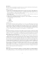
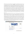
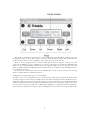
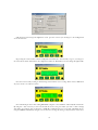
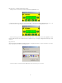
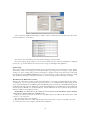
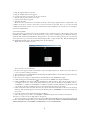
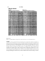
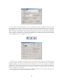
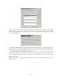
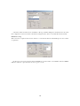
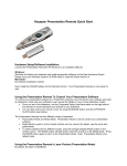
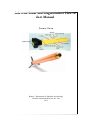
Side scan Sonar and Magnetometer How to
do it Manual
Jeremy Green
Report—Department of Maritime Archaeology
Western Australian Museum, No. 206
2013
Introduction
The system consists of four hardware components and a suite of software. This manual is intended a guide to
setting the system up and working it on Seaspray or any other vessel
Hardware components
1. Computer that can be the PC desktop mounted in the remote sensing consol or a laptop of PC or Mac version.
2. Marine Sonic Sea Scan HDS (High Definition Sonar), consisting of a dual frequency (300/900 KHz) tow
fish, a tow weight, 2 two cables (30 m and 100 m), a Standard Topside Unit (STU) interface box, power
cable and the software to run the Sea Scan is Sea Scan Survey.
3. Marine Magnetic Explorer overhauser magnetometer consisting of a tow fish, 50 m cable, electronics box
and Sea Link software.
4. Trimbel OmniStar Omnilight 132 with antenna, power supply and control box.
5. Computer either a desktop PC (the usula boat configuration), a Mac with VMFusion or a PC Laptop all
loaded with necessary software which includes:
1. Sea Scan Survey
2. SeaLink
3. SonarWiz
4. AgRemote
5. HyperTeminal
COMs Port Issues
If you are using the desktop PC, it has four COMs ports (3, 4, 5 & 6 on two additional plug in cards) and an
array of USB ports. In general the GPS OmniStar Data port A is in COMs Port 3, Data Port B will be COMs
4, Garmin GPS is in COMs 5 and the Magnetometer is in COMs 6. If you are going to use a fathometer this
will have to plug into a COMs port, probably remove the Garmin from COMs 5. The Sea Scan HDS plugs into
a USB port. There really should not be a problem as long as you know which peripheral is plugged into which
port. If you are using a laptop, they generally do not have COMs ports so read Laptops below.
Laptops
Because most modern laptop computers do not have COMs ports, a Keyspan adapter is needed convert COMs
port connections to USB so that it can then be connected to a USB port on a laptop. Also, because laptop and
computers usually only have two USB ports, a USB Hub may also be needed that will allow up to four USB
connections to connect to a single USB port on the computer. In general the only requirement is that there is a
Keyspan connector to convert COMs ports for the GPS, magnetometer and fathometer into USB connections
and an additional USB port for the side scan
The Keyspan connections are a little tricky because each COMs connector, via a Keyspan, is allocated a new
COMs port number on the computer in no particular order, so when everything is connected to the hub, there
is generally no way of knowing what COMs Port number is allocated to what device. It is useful to allocate the
same port number to each software program rather than having to reset the COMs port for each program every
time you start up. To do this, remove all USBs from the hub and connect the hub to the computer. Then connect
the USB coming from the OmniLite KeySpan. This will then allocate COM3 to the Keyspan (COMs Port 1 &
2 sometimes already taken in hardware, do not really exist and are thus irrelevant). The next COMs hardware
item you connect to the Hub via a Keyspan will then be allocated COM 4 and so on. So to ensure you know
what the COMs port is for each piece of equipment, make sure that you connect in the sequence OmniLite
(COM3), Magnetometer (COM4), etc., in that order. We do this because the software programs remember
which COMs Port it was last connected to, so by doing it this way we always know that the same hardware will
always be connected to the same COMs Port. Because the side scan does not use a COMs port, but connects
directly via a USB connection it does not come into this.
Keyspan Issues
Keyspan can be a bit of a problem at times, usually it is to do with the computer not recognising the Keyspan.
This can happen on a PC or, on a Mac on the PC side. If you are having problems on a PC with the COMs port
not recognising the Keyspan, go to the Start menu; Right-Click Computer and select Manage. In the Computer
2
Management List select Device Manager. Click on box against Ports (COM & LPT) and you will see a list of
ports, usually Communications Ports (COM1), (COM2) and you should have Keyspan USB Serial Port (COM3)
and other Keyspan Ports if they are connected; the Printer Port is irrelevant. If the Keyspan USB is not there,
try unplugging the USB connector from the computer and plugging it in again after a few seconds the Ports list
should refresh and you should see the USB Keyspan. If this does not happen you have a driver problem. Go to
the Universal Serial Bus controllers in the Device Manager and you should see a Keyspan USB Serial Adapter.
If it is not there then you will need to reinstall the Keyspan driver. Look for USA-19HS application that installs
the driver and install the Keyspan driver. Sometimes there is an exclamation mark or symbol next to the serial
adapter icon indicating the driver has a problem. You can open the Keyspan USB Serial Adapter and in Driver
tab select Update Driver. That should resolve the problem. On the Mac side, all of the above are options apply,
but first, in VMFusion Menu bar, select Virtual Machine and scroll down to USB and Bluetooth and check that
the Keyspan is connected to the PC side. It should say Disconnect Keyspan USA-19H, meaning it is connected
to the PC side, if it says Connect Keyspan USA 19-H it means that the Keyspan is connected to the Mac side
and need to be connected to the PC side, so click that. Plugging in the Keyspan USB connector usually defaults
to the PC side but on occasions it will ask if you want to connect to the Mac or Windows, or occasionally it will
automatically connect to Mac side, depending if someone has checked the button to always connect to the Mac.
Monitor issues
The desktop computer and laptops have an option to connect to a second screen which is a great advantage when
dealing with multiple windows that most of the programs you will be dealing with have. Sometimes there are
slight problems with this. On the desktop PC, it is pretty straightforward, having two separate screens (see PC
screens below). For laptops on the Mac, go to VMFusion on the Mac side and in the VMFusion menu View
menu there is an option for a single screen, which means you can have the PC side open on one screen and
other Mac programs open on the second screen. In Full Screen the PC is on both screens and there is no Mac
side visible. In this situation on Seaspray where the laptop is below the second screen it is useful that the cursor
moves upwards off the laptop onto the second screen and not appear out of some other side of the screen which
can be really confusing. The configuration setup for the position of the screens has to be done on the Mac side
using System Preferences/Displays/Arrangement. Here you can move the screens around to this configuration.
Also when you are back on the PC side in VM Fusion, remember if you should need to access the Mac side you
can do this by moving the cursor to where the dock is and the dock will appear. It is useful to keep the dock at
bottom of the main laptop screen and the second screen above. In a PC computer, the Control Panel/Appearance
and Personalization/Display/Screen Resolution as shown below:
3
Screen 2 should be moved to above screen 1 as shown below:
The DGPS
The GPS/DGPS is the essential part of the operation. Currently we are using a Trimble OmniLite which is a
simple unit providing position data, coming in NMEA sentences, but can be a real pain to configure if you don’t
know how to do it. The NMEA sentences give position and course and are accepted by the software programs to
provide position information. It is worth remembering that there are lots of different NMEA sentences, but the
ones we need are GGA and VTG, do not select any others as they are not necessary. The OmniLite can be setup
using the program AgRemote. The system is mains powered and is turned on by pressing the On/Off button on
the front of the unit. See below.
On the rear of the unit is the power input socket, the aerial socket and two data ports A & B (always use
A). The reason for two ports is that you can configure it with Port B and this does not disrupt or effect Port A
until the settings are saved. So do all AgRemote configuration with data cable plugged into Port B and then
connect to Port A. There is a OmniLite instruction manual OmniLite132-doc-user-manual.pdf. The system
should be set so that the communications interface is 9600 N 1 (meaning 9600 baud, No Parity and one stop
bit). In general, the other software packages are set up with the same protocol that will ensure that they can all
communicate correctly. Once the protocol is configured it should, in theory, always remain the same. There is an
AgRemote Software instruction manual AgRemote.pdf. Unless something odd happens to the unit, or you have
to set up a new unit, these settings should remain the same. The only problem I have found is that occasionally
there seems to be a bad connection in the power socket and it needs to be wiggled and occasionally it resets itself
and thus does not communicate properly. If the unit is not responding properly you need to reset the PortA
configuration (see below).
To start operations, the antenna must be connected, the communications cable connected to Data A (via the
Keyspan if you are using a laptop as described in COMs Port Issues above) and the OmniLite powered up. The
Data Port A light should then start flashing showing the system is working. Open AgRemote, select Connect
from the File Menu, select the COMs port and check that the screen shows something like this:
4
The D\3D on the Home screen means that you have differential signal. Remember, buildings can screen
the OmniStar satellite so ensure that you have a clear view of the sky when doing this. The sv gives number of
satellites. If that is OK you can close AgRemote and continue the set up of the side scan.
However, before setting side scan, it is worth checking that the system is using the correct protocol. You
can do this in AgRemote, but it is advisable not to, because of the danger of resetting the OmniLight. The
simplest is to go to HyperTeminal, and check the data is coming through correctly, you should see text rather
than lots of funny symbols (For HyperTerminal see below). If it is not working correctly, OmniLight needs to
be reconfigured (see below).
In the worst case scenario, if for some reason the OmniLite fails to work, it is always useful to carry a backup
which is a Garmin GPS (see Garmin Setup below).
Configuration of communication protocol on OmniLight
In order to set the correct communications protocol, the baud rate, parity and stop bits must match the normal
operating settings. To do this remove the COMs connector from Port A and plug it into Port B. This allows us to
change the settings on Port A and to be sure the settings are properly saved. Select Connect from the File Menu
and in the Settings select Auto Port Configuration and ensure you have correct COMs port number (note it is set
to look at what is connected to COMs port 3). This will allow AgRemote to communicate with the OmniLite no
matter what the communication settings are. Note in the figure below, shows what the settings should look like.
5
OK that and you should get the AgRemote screen. press the < button you should get to the Configuration
screen shown below:
By pressing the ∨ button first to Enter Configuration and then the < button until you get to you will get to
the screen shown below which allows the configuration of Port A. (Remember you are working through Port B):
Press the ∨ button and you will get the following screen with the correct settings. If the screen is different in
any way it needs to be edited to match.
Note I means Input, that is data coming FROM the computer to the OmniLite, and usually this is irrelevant.
By using the > and < buttons you can scroll around the screen to the place where you want to make a change
and change, for example, what is after the I to TSIP. The communication protocol is 8N1, and finally the O =
Output is NMEA and 9600. By using the ∧ and ∨ buttons to change the setting so they match the screen above.
6
Now press the ← and that will enter the settings.
Next press the ∨ button and you will see the following NMEA1 screen:
Ensure that GGA is in uppercase (activated) and all rest are lowercase (deactivated). Now press the ← and
that will enter the settings. Next press the ∨ button and you will see the following NMEA2 screen:
Ensure VTG is uppercase and rest are lower case. Press the ← and exit the screen. Close AgRemote return
the data cable to Port A. You should now have the OmniStar set up to the right configuration and ready to work
via Port A.
HyperTerminal
You can check if the OmniLight is working properly by using HyperTerminal, a simple communication package.
Open the program, you will see following screens:
Give the connection a random name. OK and the next screen is the protocol screen:
7
Select connection COM3 and in Settings set 9600, 8, None, 1. OK and you now should see the data stream
from the OmniLite as shown below:
Note this has the GGA and the VTG with the E 2 meaning you have DGPS.
If you have garbage, funny symbols or no real text that makes any sense, then the OmniLight is configured
incorrectly, so go back and follow the instructions for setting up OmniLight with AgRemote.
Garmin Setup
This is pretty simple; the hand held instrument has an external antenna and a communications cable. Mount
the antenna on the roof or a high point. Switch the machine on press Page button to navigate to page that has
Settings icon. Select settings and press Enter and navigate to Interface and press the Enter button. The Serial
Data Format should be NMEA In/NMEA Out, if it is not then change to that setting. Note baud rate is 4800
and can NOT be changed, so Navigation interface on software packages should be changed accordingly.
The Marine Sonic HDS Side Scan Sonar
The side scan comes with a tow fish, 2 cables (30 m and 100 m), a tow weight, a Standard Topside Unit (STU),
a USB pig-tail, a power cable and the Sea Scan Survey software. It is recommended that before using the side
scan you read the manuals Sea Scan HDS Quick-Start Manual.pdf, Sea Scan Survey Software Manual v2.5.0.pdf,
Standard Topside Unit Operators Manual v2.0.1.pdf, Standard Towfish Operators Manual v1.2.0.pdf and Towed
System Operators Manual v1.1.0.pdf. Probably the Software Manual is the most useful but the Quick Start
manual is useful for an equipment overview.
REMEMBER: DO NOT PLUG OR UNPLUG ANY CONNECTION BETWEEN THE TOWFISH
AND THE STU WHEN THE STU POWER IS ON.
Follow the connection instructions in the Sea Scan HDS Quick-Start Manual. The yellow Power Cable
connects to a 12 volt battery.
The sequence from the start should be:
1. Plug the towfish cable into towfish, tighten with spanner and connect tow point on the fish to the cable.
2. Connect the STU to the computer with the STU’s USB cable.
8
3.
4.
5.
6.
7.
8.
Plug the pigtail cable into the STU
Plug the towfish cable into the pigtail
Connect the yellow power cable to the 12 volt battery
Plug the yellow power cable into the STU
Open Sea Scan Survey program
Turn ON the STU
However, if the system has been used before and is all connected up, simply attach the towfish cable to the
towfish as in #1 above. Connect yellow cable to battery and turn on the STU. Note: on occasions the STU
towfish fuse has blown so there is no power. Check the fuse with a multimeter (in the yellow case) and replace
if necessary (250mA fuses).
Sea Scan Survey HDS
In Sea Scan Survey program, make sure the waterfall screen is visible (see below). The interface can be quite
muddled with 9 different screens, in the View menu you can close everything except the Menu Bar that you
will need. If by accident the Menu Bar has disappeared too, this can be restored by putting cursor on Sea Scan
Survey bar at the top of screen that is blue and pressing Alt (PC) or Option (Mac) key. This should bring back
the Menu Bar with File, View, Tools and Help. Now do the following:
Right click the waterfall (see below)
You now need to do the following:
1. In the box that appears Click Sonar Interface. Select Standard Topside Unit. If button says Start click it, if
it says Stop then its already connected.
2. At bottom right of screen SONAR Status should change from Red to Yellow to Green and read Sonar Connected.
3. The system is now connected.
4. Now activate the navigation, right click the waterfall and select the NMEA Data input.
5. Click on Navigation and Fathometer
box and you will see NMEA Data Input and Plotter.
6. Click on NMEA and the screen will show Available Ports and Open Ports. If it is in the Open it is best to
reconfigure it just in case. Select it and click the Remove button. It now should be in the Available. Select it,
set Baud Rate to 9600 if it is the Trimble (or 4800 if its Garmin) and click Add. Press the Test button and
you should see the Test Communications screen with Latitudes appearing in the strings.
7. Click on File menu and select New from the drop-down menu. Enter the name of the survey in the Enter
Name for. This should be the place, then entre the data file prefix as a YYYMMDD. You can add a description
if you wish.
8. Open the Sonar Control Window from the View Menu.
9. Select the frequency you wish to use 300 KHz or 900 KHz and press the Sonar Power ON button
10. Carry out a rub test for both high and low frequencies
To close down turn power OFF in the Sonar Control Window. In File Menu select Close which will save all
the data. Turn off STU and disconnect power cable from battery. DO NOT UNPLUG ANYTHING BETWEEN
THE TOWFISH AND STU WHILE CONNECTED TO 12 VOLT BATTERY
9
Marine Magnetics Explorer
The Marine Magnetics Explorer consists of a towfish, 30 m cable, SeaLINK software and isolation transceiver
box (ITB) which has 3 connections for the battery (Power see below), COMS Port (COM) and towfish cable
(FISH). To start the magnetometer connect the towfish to cable, the cable to the interface box, the ITB to 24
volt battery supply (2 small 12 volt gel cells) and the COMs cable to the computer. Read the Explorer Operation
Manual v121R.pdf.
To set this up, connect all the above. The ITB box has two LEDs: Power and Comm (see below).
When connected to the power supply the Power LED is illuminated, when it is communicating with the
fish the Comm LED flashes.
There are a few issues with the magnetometer. Start up the SeaLINK software and see if the magnetometer
is working. You may be asked for registration details which are: Name (Registered User), Company (Western
Australian Museum) and Serial Number (25220604). You should locate the towfish far away from any big iron
objects (cars, etc.) and away from any non-ferrous metal (c. >1 m). On a pole is OK or on a plastic crate on the
grass somewhere. Open SeaLINK and set Port 1 to 6 for the computer (or 4 for a laptop because the Magnetometer
will have taken COM4 following the navigation that has COM3), check the SeaSpy ITB and uncheck Read
Depth. Port 2 should be set to a large number (10) and ITB and Depth unchecked, and the Baud rate 9600. Do
not enable NMEA GPS if you are operating the Explorer by itself (in the case of a laptop the COMs Port will
be COM3 and baud 9600). OK that and you should see a brief identification message in the message window,
the bottom window in SeaLINK. Check everything is working by sending a Command D from the Command
Menu. This gives signal current in the first column which should be between 0 and 255 nominally less than 10
in operating environment. The second column is battery voltage and the third the temperature of the electronics.
Once deployed send Command 1 which will give fastest sampling rate of 4 Hz. Occasionally the magnetometer
gets a bit lost and asks you to set the Julian day. This can be obtained from table below. It is usually formatted
2013jjj where JJJ is Julian Day given in 3 figures, thus: 001, or 012, or 234.
10
BOB Software
BOB is a new Marine Magnetics magnetometer software that I have not yet tried. Watch this space.
SonarWiz
SonarWiz is a software program that allows for integrating side scan, magnetometer, fathometer and GPS. It is
probably the main software package we would use as it integrates all the aspects and is quite user friendly. It only
works with a dongle. To start with read the software manual SonarWiz_UserGuide.pdf. You will have to insert
the dongle before starting the SonarWiz (Laptops ensure that you have none of the COMS ports connected).
If you are starting a new survey, set the COMs Ports to the correct settings (LAPTOPS do this before connecting
the USBs, as before, insert GPS first, then Side scan (this is not a COMs connector simply a USB cable), then
the Magnetometer COMs connectors. Then you know that GPS is COM3, Mag is COM4 and if you connect
a fathometer, that will be COM5) for PCs the COMs ports are set and fixed and you do not have to worry
about settings apart from knowing what device is connected to what COMs port. When the program starts up
you will see checking licenses window. If not it will get an evaluation request that means it has not recognised
the dongle. If this happens it will be necessary to check the USB Controllers in the Device manager (see above).
11
You can either open an existing project or start a completely new project by clicking on New in the File
drop-down Menu. You will get the above window. Fill in the vessel’s name and the Project Name with prefix
YYYYMMDD and nominate the folder where this will reside. The Approximate Project Position can either be
filled in manually, obtained from Get From File, from the GPS if it is connected, or from Select from World
Cities. Coordinate source should be Auto and smoothing 300 and Coordinate System Auto selected. In the main
window under Data Acquisition there should be three flashing icons in the bottom bar, showing that recording,
sonar and Navigation are not configured, as per below:
The first step is top configure the Navigation input. In the main window under the Data Acquisition Tab
there is the Navigation button. Press this and you will get the screen above. Enable Nav IO. Input source NMEA,
NMEA Record Types should be GGA and VTG, set the Serial Port to the correct port number and Serial Port
Configuration to 9600 baud, 8 Data Bits, 1 Stop Bit, Parity None. Miscellaneous check Formatted Navigation
File which will store incoming navigation data in a file. Do not check Use SonarWiz Computed Speed. Check
Compute Towfish Position. OK that.
Now configure the Side scan. In the main window under Data Acquisition select the Side scan button and
you should get the Select Sonar Interface window shown below:
12
The Current Side scan Server should be LOCAL: Marine Sonic HDS and the SubBottom should be blank
because we are not using one. The Local Server window AutoStart sould be selected and Marine Sonic HDS
Server Ver 5.00.002 should be selected. Ignore the rest. Select Start/Configure in the Side scan and you should
get the following window:
This shows the MSTL STU V1.0 selected and various other boxes and windows showing status of Side scan.
Press the Connect button and this should fire up the system. Note this is where you set the resolution (set 12-bit
as preferred option), sonar range set depending on High or Low Frequency (Low frequency set maximum range
to no more that 400 m and on High Frequency about 50 m).
Occasionally screens do not appear for one reason or another, the screens are to be found in View/Data
Acquisition Views where there is a list. On occasions when opening a particular View it does not appear. In this
case use the Help/Restore Window Locations so the open windows will all appear and you can move them around.
Magnetometer set up
The Magnetometer is set up by selecting the Magnetometer button in the Data Acquisition menu. The following
window will appear:
13
Check the enable Serial IO and set COMs Port. The type is Marine Magnetics Standard and set the Serial
Port configuration as discussed earlier. Check Record magnetometer data box and click File Format Default.
Fathometer set up
This is a bit more complicated because the data has to come from the Furuno GP 18070F plotter echo sounder
or equivalent.
In this case it is necessary to find out what the Baud Rate is of echosounder, set COMs Port and select NMEA
DBS. You will have to play with this one a bit to get it to work.
14