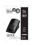
1
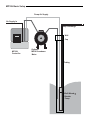
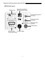
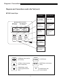
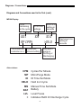
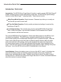
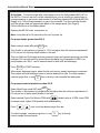
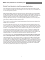
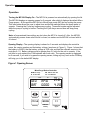
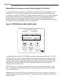
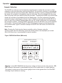
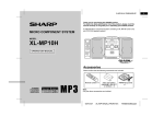
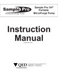
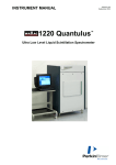
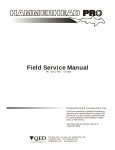
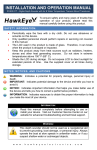
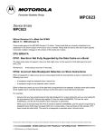
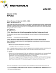
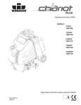
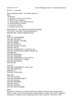
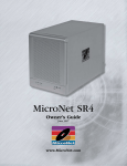
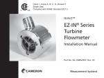
U
O
asics
MODEL
MP10H
CONTROLLER
PATENT PENDING
Instruction
Manual
Part No. 95195
11-20-14
P.O. Box 3726 Ann Arbor, MI 48106-3726 USA
1-800-624-2026 Fax (734) 995-1170
[email protected] www.qedenv.com
MP10H Basic Setup
Pump Air Supply
Air Supply In
Pump Discharge
Well
Cap
MP10H
Controller
Optional
MP30 Drawdown
Meter
Tubing
Well Wizard
Bladder
Pump
R
Contents
Topic
Page
Safety Warnings
1
Conventions and Diagrams
2
Introduction / Quick-Start
5
Bladder Pump Operation in Low-Submergence Applications
7
Turning the MP10H On
8
Opening Display
8
Manual Mode for Pumps Located at Depths Over 250 feet
9
Using CPM
12
Sample Collection
14
Flow Throttle Use
15
Use with the MP30 Level Sensing Water Level Meter
16
ID Mode
18
MP10H Battery
19
Troubleshooting
20
MP10H Specifications
21
QED Service Contacts
21
QED Warranty
22
Appendix 1 ID Data Table
24
Appendix 2 MicroPurge Pump Specifications
25
Safety Warnings
Safety warnings
Compressed air - Use caution when working with compressed air or gas. Compressed gas
cylinders are under extreme pressure and can cause unrestrained hoses to whip about dangerously. Do not over pressurize your controller. Failure to operate the controller within the pressure limits could result in failure. Read all operating instructions before operating the MP10H
controller.
Warning! - Do not disassemble the pneumatic pump while it is connected to a compressed gas
source. Dangerous pressures could cause injury.
Warning! The MP10H Controller is designed to operate on high air pressure, up to 300 PSI.
Read all instructions before operating and follow all safety guidelines! Failure to do so may
cause serious injury or death.
Use only the hoses and connecting fittings supplied with the MP10H and accessories from
QED - DO NOT MODIFY OR SUBSTITUTE THE FITTINGS OR HOSES. Do not supply the
MP10H with compressed gas at pressures greater than 300 PSI. Be certain of the gas
supply source pressure before you connect it to the MP10H. Do not modify the fittings on
any well caps to allow connection of the MP10H to sampling pump systems not intended for
use with the MP10H; applying higher pressure than intended to sampling pumps can damage
the pumps and tubing and cause injury or death to persons nearby. Connect the MP10H only
to pumps located within the well in their normal operating position; DO NOT use the MP10H
to operate pumps outside the well.
1
Diagrams and Conventions used in the Text
MP10H Panel Layout:
Battery Cover
MODEL
O
U
s
asic
ED
Connector for optional
MP30 Drawdown Control
MP10H
Compressed gas source
connection
CON T ROLLER
MicroPurge Mode Quick Guide
1. Opening cover turns power ON. (Close to turn OFF.)
2. Select desired Cycles Per Minute (CPM) with the
key
(default value is 4 CPM).
3. Turn throttle to set depth on gauge to 10-20 feet
deeper than the pump location in the well.
4. Press CYCLE to START pumping.
5. When water discharge begins, adjust throttle until
a slow, steady flowstream is achieved.
6. Press
keys to set the desired purge flow.
7. Use II key to directly control sample flow and pause.
CONTROL PORT
AIR IN
3 AA BATTERIES INSIDE
ED
MP Micro Purge
ID ID Time Set
Time
MN Manual Time Set
LVL LevelShutoff
ID
Controller to pump
connection
1-800-624-2026
micropurge.com
MicroPurge Basics Controller
Refill
AIR OUT
00.1 103 10.0
MP CPM4 >05.0
Mode
DISCHARGE CYCLE
Discharge
CPM
CPM/Value
Flow/Value
CYCLE
MODE
II
Start/Stop
ID/MN/MP/
Battery
Hold/Sample
/Cycle
Discharge cycle
indicator
Flow throttle
Flow/Value
ED
0
psi
THROTTLE
MP10H Control
Pressure Gauge
Keypad and display
2
Diagrams / Conventions
Diagrams and Conventions used in the Text (cont.)
MP10H Control Keys:
In MP Mode
In Other Modes
Cycle Per Minute
key - Changes
cycle per minute
Scrolls cursor
Faster key Speeds up flow
Changes a value
at the cursor
location
Slower key Slows down
flow
Changes a value
at the cursor
location
MicroPurge Basics Controller
MP Micro Purge
ID ID Time Set
Time
MN Manual Time Set
LVL LevelShutoff
ID
Refill
00.1 103 10.0
MP CPM4 >05.0
Mode
Discharge
CPM
CPM/Value
Flow/Value
Flow/Value
CYCLE
MODE
II
Start/Stop
ID/MN/MP/
Battery
Hold/Sample
/Cycle
Pause key Pauses flow for
sampling
Mode key -Selects
the operation
mode. Also battery
check
ED
Cycle key -Selects
Start and Stop of
pump cycling
CPM Button (also scroll for
item selects)
CYCLE
CYCLE Button
UP Button, faster pumping
(also increase item)
MODE
MODE Button (also battery
check)
DOWN Button, slower
pumping (also decrease
item)
II
3
PAUSE Button (also
manual sample)
Diagrams / Conventions
Diagrams and Conventions used in the Text (cont.)
MP10H Display:
Time
remaining
in the cycle
ID for time
settings
103
00.1
MP CPM4
The mode the
controller is in
Refill time
setting in
seconds
10.0
>05.0
Cycles per
minute setting
Discharge time
setting in
seconds
Indicates if
pump is
Refilling or
Discharging
Abbreviations:
CPM
MP
ID
HELD
MN
BAT
LVL
>
Cycles Per Minute
MicroPurge Mode
ID Time Set Mode
Held In A Cycle
Manual Time Set Mode
Battery
Level Pause
Indicates Refill Or Discharge Cycle
4
Introduction/Quick Start
Introduction / Quick start
Introduction: The MP10H Micro Purge Basics Controller is used to operate QED Well Wizard™
bladder sampling pumps to purge and sample ground water. The MP10H has specific design
features to make MicroPurge ™ sampling easier. These features include:
MicroPurge Mode Operation Simple Increase / Decrease keys allow you to easily set
the flow rate you need for each well.
ID Time Set Mode Operation Quickly recalls pre-determined settings for each well by
specifying a 3-digit ID.
Level Delay Interface The controller plugs into the optional MP30 MicroPurge Drawdown / Water Level Meter to provide direct feedback of well drawdown and to pause
pump operation until the level recovers.
The optional MP30 MicroPurge Drawdown / Water Level Meter plugs into the MP10H to provide water level feedback. The MP30 uses a standard conductivity probe to detect the
ground water surface and a marked tape allowing the user to measure the depth. When the
meter is set in MicroPurge mode, the probe is lowered a specific distance below the static
water level and fixed in this position. During well sampling if the water level drops below
the user-set probe position, the MP10H is paused which prevents further drawdown by the
pump. Once the level recovers the MP10H begins pump operation again, starting in the pump
refill cycle. Use of the MP10H with the MP30 is detailed later in this manual.
Insert Batteries: Remove the battery cover on the top of the MP10. Insert 3, AA alkaline batteries into the battery holder and carefully replace the holder in the carrier. Replace the
battery cover and tighten the 4 screws. Batteries should last for about 6-8 weeks of typical
full-time field use. If the MP10H will be stored longer than about 3 months, the alkaline batteries
should be removed to prevent leakage.
5
Introduction/Quick Start
Quick Start: Connect the light blue coiled pump hose to the fitting labeled AIR OUT on
the MP10H. Connect the red (or black, depending on your air source) air supply hose to
a compressed air or gas source and connect it to the fitting labeled AIR IN on the MP10H.
Supply up to 125 psi compressed air or gas to the controller. Turn the controller throttle
until the gauge reads the approximate depth of the sample pump (See Page 6).
Follow instructions on the battery panel:
Opening the MP10H case turns power on.
Note: It may take up to 20 seconds for the unit to power up.
For pump depths greater than 250 ft
Select manual mode (MN) with
MODE
key
Turn throttle to set pressure on gauge to 12-16 psi higher than the minimum requirement
of 0.5 psi per foot of pump depth location in the well.
Then set Refill and Discharge times as needed to begin and optimize pumping; use initial
settings of 30 seconds each for both refill and discharge for pump depths to 300 ft; for
pump depths over 300 ft., use 60 seconds each for both refill and discharge.
Press Cycle to START pumping.
When water discharge begins, adjust throttle until a slow, steady flowstream is achieved.
Then adjust refill and discharge times to achieve desired flow rate. To collect samples,
continue purge flow, or use
II
key to directly control sample flow and pause.
For pumps located at depths less than 250 ft.
Select MicroPurge mode (MP) with
MODE
key
Turn throttle to set pressure on gauge to 4-8 psi higher than the minimum requirement of
0.5 psi per foot of pump depth location in the well.
Select desired Cycles Per Minute (CPM) with
(default value is 4 CPM, lower CPM
for deeper wells, higher CPM possible with shallow wells).
Press
keys to set the desired purge flow rate.
To collect samples, continue purge flow, or use
control sample flow and pause.
6
II
key to directly
Bladder Pump Operation in Low-Submergence
Bladder Pump Operation in Low-Submergence Applications
Pump submergence is defined as the height of the static water column above the top of the
pump. In wells in which this water column height is 5 feet or less, the pump is considered to be
in a low-submergence application.
QED sampling bladder pumps fill by hydrostatic pressure. As the inside of the pump's bladder
fills with water, the bladder expands. This filling and expanding of the bladder is referred to as
the "refill" half of the pump cycle. When air pressure is applied to the outside of the bladder, the
bladder is squeezed, forcing the water up the discharge tubing. This is referred to as the
"discharge" half of the pump cycle. In low-submergence applications, there is less water pressure available to expand the bladder during the refill.
This can result in a smaller volume of water being pumped with each pump cycle because the
bladder may not fully expand.
As a result of the lower volume per cycle, more time will be required to bring the water to the
surface. An easy way to verify that the pump is working, prior to the water reaching the surface,
is to submerge the pump's discharge tubing in a beaker of water. Each time the pump goes into
discharge, air in the discharge tubing, which is displaced as the water level in the tubing rises,
can be seen as air bubbles coming from the end of the tubing. To optimize the pumping rate,
the refill time should be set long enough to achieve the maximum volume of air bubbles on
each pump cycle, and the discharge time should be set long enough to ensure that the air has
stopped bubbling out of the tube before the pump controller switches back into refill.
In low submergence wells, it is critical that the air pressure driving the pump not be more
than 10-15psi higher than the minimum re-quirement of 0.5 psi per foot of pump depth.
Higher pressures than this can cause the bladder to be squeezed too tightly during discharge,
a condition which can prevent the bladder from expanding during refill. To avoid this condition
in deeper wells, it is suggested that the air pressure applied to the pump be gradually increased
as the water level in the pump's discharge tubing rises. It is recommended that the air pressure
be set at 15 psi initially, and slowly increased in increments of 10 psi as needed until the water
reaches the surface. Submerging the end of the discharge tubing under water as described
above will verify whether the air pressure is set high enough.
7
Operation
Operation
Turning the MP10H Display On - The MP10H is powered on automatically by opening the lid.
The MP10H displays an opening screen for 5 seconds, after which it displays the default MicroPurge screen. At this point the MP10H is in MicroPurge mode (MP) but not cycling the pump.
This initial state allows the user to adjust time and throttle settings before the pump starts to
operate. Pressing the Cycle key begins pump cycling. Times and modes may be adjusted
while the pump is cycling or before. Pressing the Cycle key a second time will stop pump
cycling.
Note: all user-entered time settings are lost when the MP10 is turned off. Also, the MP10H
automatically powers down when the lid is closed, so make sure the MP10H is stored with its
lid closed.
Opening Display - The opening display is shown for 5 seconds and displays the controller
name, the version number and the battery voltage, (as shown in Figure 1). Figure 1 shows that
the battery is GOOD, that the battery voltage is 4.20 volts and that the software version in the
controller is 1.0. Battery voltage must be greater than 3.6 volts for the unit to operate. If the
unit fails to cycle replace the 3-AA batteries with fresh cells. The opening screen is displayed
for 5 seconds, if you wish to by pass the opening screen, hitting any key, such as the CPM key
will bring you to the default MP display.
Figure 1 Opening Screen
MicroPurge Basics Controller
MP Micro Purge
ID ID Time Set
QED
BAT
Mode
Time
MN Manual Time Set
LVL LevelShutoff
ID
Refill
MP10
GOOD
V1.0
4.20
CPM
Discharge
CPM/Value
Flow/Value
Flow/Value
CYCLE
MODE
II
Start/Stop
ID/MN/MP/
Battery
Hold/Sample
/Cycle
8
ED
Operation
Manual Mode For Pumps Located At Pump Depths Over 250 Feet
For deep wells manual mode (MN on the display), is useful for manually setting refill and discharge times on the controller as in traditional controllers (like previous model QED pump
controllers). An example of the MP10H in Manual Mode is (shown in Figure 2). Manual Mode is
also used when there are other conditions where one of the 165 possible preset times of ID
and MP modes will not match your needs. MN mode is entered when the MODE key is
pressed twice from the default MP mode.As shown in Figure 2, the display indicates MN mode
in the lower left corner and CPM and ID are not displayed.
Figure 2 MP10H Manual Mode (MN mode)
MicroPurge Basics Controller
MP Micro Purge
ID ID Time Set
MN Manual Time Set
LVL LevelShutoff
ID
Time
Refill
00.1 1 03 1 0.0
M PC P M 4 >05.0
Mode
Discharge
CPM
CPM/Value
Flow/Value
Flow/Value
CYCLE
MODE
II
Start/Stop
ID/MN/MP/
Battery
Hold/Sample
/Cycle
ED
In Manual Mode the CPM and UP, DOWN keys function differentlythan MP mode. The CPM
key becomes a key used to select the digits of the refill and discharge time settings found at
the rightmost positions on the display. The UP and DOWN keys are used to adjust the digit
value up or down. By selecting and adjusting digits up and down a user can quickly set any
time from 00.1 seconds to 999.9 seconds. Sampling in Manual Mode is the same as
explained, above, for MP mode.
The MP10H does not attempt to translate a user set time into a corresponding ID or CPM.
Also, any settings you have entered in MP or ID modes are lost once you press the MODE
key to enter MN mode.
Note:changes in time settings that are entered while the controller is cycling are reflected on
the next cycle change (so a long refill time of 15 seconds will time out before a new refill time
becomes valid).
9
Operation
Sample Collection
The PAUSE key ( I I ) is used to freeze the controller action to allow the user time to collect
a sample or carry out other steps that might be difficult if the controller continued to automatically
cycle and cause the pump to produce water. While the controller is cycling, pressing the PAUSE
key causes the controller to immediately enter the Hold state. Drive air is vented from the pump
(this is the pump refill cycle) and the pump fills and waits. Pressing the PAUSE key a second time
causes the controller to immediately enter the Sample state. Drive air is directed to the pump
causing the pump to discharge its volume of liquid. Bladder pumps typically hold 400-500 ml of
liquid, so use of the Hold and Sample states allow the full volume of the pump to be discharged
into a sample container. Pressing PAUSE once again returns the MP10H to its normal Automatic
Cycling state. During Hold and Sample a HELD is displayed to remind you that the controller
is in a paused state. Figure 3 shows an example of the MP10H in MP mode, but HELD in the
Sample state.
Note: Pressing the Cycle key also freezes controller cycling. However, using the
Cycle key rather than the Pause key causes the startup screen to be displayed upon restart.
Use of the Pause key is recommended for typical operation.
Figure 3 MP10H Held State (MN mode)
MicroPurge Basics Controller
MP Micro Purge
ID ID Time Set
Time
MN Manual Time Set
LVL LevelShutoff
ID
Refill
H E L D 1 03 1 0.0
M PC P M 4 >05.0
Mode
Discharge
CPM
CPM/Value
Flow/Value
Flow/Value
CYCLE
MODE
II
Start/Stop
ID/MN/MP/
Battery
Hold/Sample
/Cycle
ED
Warning!: in the HELD SAMPLE state the pump, tubing and hoses are all under pressure. DO
NOT attempt to disconnect or disassemble any part of the system when it is under pressure.
The system is under prsure if the pressure gauge shows a value greater than 0 and the RED
Discharge Cycle Indicator is showing.
10
Operation
Flow Throttle Use
The flow throttle is used during sampling to regulate the pressure applied to the pump.
Turning the throttle clockwise increases the pressure and counterclockwise decreases the
pressure. The pressure gauge shows the approximate pressure applied to the pump. This
allows easy adjustment of the throttle giving pressures that will produce gentle, nonturbulent flow (normally 5-10 psi higher than the minimum requirement of 0.5 psi per foot
of pump depth). For traditional, high volume purging pressure may be increased with the
throttle to maximize pump flow during well purging.
11
Operation
MicroPurge Mode for pumps located at depths less than 250 ft.
Most MP10H users will leave the controller in the default MicroPurge (MP) mode. See Figure 4
for an example of the MP10H in MP mode.MP mode lets you to use the UP and DOWN keys to
directly increase and decrease pump flow rates.The MP10H has a broad range of other CPM
settings to ensure the availability of a time setting that will match your specific conditions. MP
mode also displays an ID, with a value of 1 to 165 that matches the flow settings (CPM and refill
and discharge times you have set). This ID should be noted alongside the well identification
(QED provides custom weatherproof ID badges for purchasers of our MP series of well caps) for
quick setting of the optimal controller settings on the next visit by using the MP10H in ID mode.
Figure 4 MP10H MicroPurge Mode
MicroPurge Basics Controller
MP Micro Purge
ID ID Time Set
Time
MN Manual Time Set
LVL LevelShutoff
ID
Refill
00.1 1 03 1 0.0
M PC P M 4 >05.0
Mode
Discharge
CPM
CPM/Value
Flow/Value
Flow/Value
CYCLE
MODE
II
Start/Stop
ID/MN/MP/
Battery
Hold/Sample
/Cycle
ED
Using CPM
The MP10H introduces a simpler way to control bladder pump flow rate and achieve the low-flow
method used by experts. Up/down arrow keys are used to adjust pump flow even at very low rates,
with excellent control and repeatability.
With previous bladder pump controllers, a leading low-flow technique called for selecting the
number of pump cycles per minute, then adjusting the bladder pump discharge and refill times to
achieve the desired volume per cycle. These adjustments were interrelated, complex, and varied by
operator. The new MicroPurge Mode (MP) of the MP10H builds in a "cycles per minute", or CPM,
method of flow control.
12
Operation
With this method, the number of complete pump cycles per minute is fixed, within a range of 1
to 6; 4 CPM is the default value which appears at startup. Each time the up/down arrow keys
are pressed, the pump refill and discharge times are both automatically adjusted to maintain the
selected CPM value. Each adjustment increases or decreases the volume pumped per cycle,
and the per-minute flow rate is the volume per cycle X the CPM value.
For example, with a 4 CPM setting, 60 ml volume per cycle equates to 4 X 60 = 240 ml/min flow
rate. A single press of the Flow up-arrow key could change the volume per cycle to 80 ml, for
example, resulting in a new, increased flow rate of 4 X 80 = 320 ml/min. And the MP10H assigns
a unique identification value to each setting, the ID value, which can be directly set during later
sampling events.
"MP" displayed in the lower left corner of the display indicates MicroPurge mode.The default CPM
setting of 4 cycles per minute is a good starting point for wells with depths from 25-100ft. MicroPurge mode starts at a time setting of 10 seconds refill and 5 seconds discharge, close to optimal
for many wells. This startup settings corresponds to a 4 cycles per minute setting (CPM4) and an
ID setting of 103.
Using the CPM key will change the CPM setting on the controller. The range of CPM settings is
CPM1 through CPM6. CPM changes like this each time you hit the CPM key: 4 5 6 1 2 3 4 5,
etc. The UP and DOWN keys change the flow rate directly, by altering the refill and discharge
times within a CPM setting.
Note: changes in settings that are entered while the controller is cycling are reflected on the next
cycle change (so a long refill time of 15 seconds will time out before a new refill time becomes
valid).
13
Operation
Here is an example of the use of the UP (faster) key:
Key
Press
Refill
(sec)
Discharge
(sec)
ID
--1
2
3
10.0
9.5
9.0
8.5
5.0
5.5
6.0
6.5
103
104
105
106
Each of the 165 possible ID settings corresponds to a unique ID that is associated with CPM,
refill and discharge time values. For typical usage, only the UP/DOWN arrow keys are required
to set flow, and the ID number is provided for easy, direct return to past settings. Appendix 1
lists all possible ID settings and the default refill and discharge time settings for each CPM.
Appendix 1 also shows how the refill and discharge time will change within a CPM setting as
you press the UP or DOWN keys.
Sample Collection
The PAUSE key ( I I ) is used to freeze the controller action to allow the user time to collect a
sample or carry out other steps that might be difficult if the controller continued to automatically
cycle and cause the pump to produce water. While the controller is cycling, pressing the PAUSE
key causes the controller to immediately enter the Hold state. Drive air is vented from the pump
(this is the pump refill cycle) and the pump fills and waits. Pressing the PAUSE key a second
time causes the controller to immediately enter the Sample state. Drive air is directed to the
pump causing the pump to discharge its volume of liquid. Bladder pumps typically hold 400500 ml of liquid, so use of the Hold and Sample states allow the full volume of the pump to be
discharged into a sample container. Pressing PAUSE once again returns the MP10H to its
normal Automatic Cycling state. During Hold and Sample a HELD is displayed to remind you
that the controller is in a paused state. Figure 3 shows an example of the MP10H in MP mode,
but HELD in the Sample state.
Note: Pressing the Cycle key also freezes controller cycling. However, using the Cycle key rather
than the Pause key causes the startup screen to be displayed upon restart. Use of the Pause key
is recommended for typical operation.
14
Operation
Flow Throttle Use
The flow throttle is used during sampling to regulate the pressure applied to the pump.
Turning the throttle clockwise increases the pressure and counterclockwise decreases the
pressure. The pressure gauge shows the approximate pressure applied to the pump.This
allows easy adjustment of the throttle giving pressures that will produce gentle, non-turbulent
flow (normally 5-10 psi higher than the minimum requirement of 0.5 psi per foot of pump
depth). For traditional, high volume purging pressure may be increased with the throttle to
maximize pump flow during well purging.
Use with the MP30 Automatic Drawdown Control
The MP10H may optionally be used with the MP30 MicroPurgeDrawdown / Water Level Meter.
See Figure 5 for an example of the MP10H in MP mode with the controller in a level paused
state enacted by an MP30 meter.
Figure 5 MP10H Level Paused State (MP mode)
MicroPurge Basics Controller
MP Micro Purge
ID ID Time Set
MN Manual Time Set
LVL LevelShutoff
ID
Time
Refill
1 0.0
LV L
M PC P M 4 >05.0
Mode
Discharge
CPM
CPM/Value
Flow/Value
Flow/Value
CYCLE
MODE
II
Start/Stop
ID/MN/MP/
Battery
Hold/Sample
/Cycle
15
ED
Operation
Figure 6 MP10H MP30 Use
MP10H
MP10
MP30
Normal
Static
Level
Maximum Point
of Drawdown
Figure 7 MP10H MP30 Use
Connector for optional
MP30 Drawdown Control
U
MODEL
O
asics
ED
MP10H
Compressed gas source
connection
CONTROLLER
MicroPurge
Mode
Quick
GuideGuide
MicroPurge
Mode
Quick
1. Opening cover turns power ON. (Close to turn OFF.)
2. Select desired Cycles Per Minute (CPM) with the
key
(default value is 4 CPM).
3. Turn throttle to set depth on gauge to 10-20 feet
deeper than the pump location in the well.
4. Press CYCLE to START pumping.
5. When water discharge begins, adjust throttle until
a slow, steady flowstream is achieved.
6. Press
keys to set the desired purge flow.
7. Use II key to directly control sample flow and pause.
CONTROL PORT
AIR IN
3 AA BATTERIES INSIDE
ED
MP Micro Purge
ID ID Time Set
Time
MN Manual Time Set
LVL LevelShutoff
ID
Refill
AIR OUT
00.1 103 10.0
MP CPM4 >05.0
Mode
DISCHARGE CYCLE
Discharge
CPM
CPM/Value
Flow/Value
CYCLE
MODE
II
Start/Stop
ID/MN/MP/
Battery
Hold/Sample
/Cycle
Controller to pump
connection
1-800-624-2026
micropurge.com
MicroPurge Basics Controller
Discharge cycle
indicator
Flow throttle
Flow/Value
ED
0
psi
THROTTLE
16
Operation
The MP10H and MP30 are connected with a cable (see Figures 6 and 7). The MP30 is
switched into mode and the water level probe is lowered to the desired maximum drawdown level. Limiting the maximum drawdown depth limits the differential head driving flow
into the well and the velocity of the water flowing into the well from the surrounding formation
important in MicroPurge sampling. The MP10H and MP30 work together to automatically
adjust the pump operation so as to maintain drawdown at the set level. When the water level
drops below the probe, the MP30 sends a signal to the MP10H to pause pumping. Both the
MP10H and the MP30 give visual signals (and the MP30 emits an audio signal) that pump
operation has stopped because of too much drawdown. Once the level recovers, the MP30
signals the MP10H to resume pump operation. The MP10H resumes by starting in the refill
leg of the pump cycle. "DRAWDOWN CONTROL"
The normal operating mode for using the MP30 with the MP10H is:
1. Use the MP30 in standard WLM mode to determine the static water level in the well
2. Decide what the maximum drawdown for that well is during sampling
3. Lower the probe to the maximum drawdown level
4. Switch the MP30 into Drawdown Control mode
5. Begin pumping with the MP10H
6. Observe the interactions between the two devices, if the MP30 is frequently pausing the
MP10H, it may be appropriate to slow the flow down (using the DOWN key in MP mode)
to better match pump flow to well recharge.
When switched into MODE, the MP30 has a flashing red light and an optional (can be switched
off by the user) audio alarm to indicate when the probe is in the dry state. A submerged probe
in all modes is indicated by a solid green light. When the MP10H is paused by the MP30 the
MP10H display indicates this as shown in Figure 5."DRAWDOWN CONTROL"
17
Operation
If the MP30 is signaling the MP10H too frequently, the operator can slow down the pump flow
rate by using the DOWN key (effectively increasing the pump refill time period). MP30 probe
position may also be varied to provide a buffer zone for your draw-down limit and gauge rate of
pumping effect on water level in the well.
If the selected maximum drawdown level is being reached even with the lowest desirable pump
flow rate more drawdown may be required to attain equilibration, or a passive sampling approach may be required. In passive sampling, used where well recovery is extremely slow, samples are taken after just a few pump strokes sufficient to purge the pump and tubing volumes.
Additional information on the MP30 is given in the MP30 O&M manual
ID Mode Figure 8 shows an example of the MP10H in ID time set mode. Once you've used the
MP10H in MP mode and found proper settings for your wells, subsequent sampling events are
speeded along by using the controller in ID mode. Once the controller is turned on, a single
press of the MODE key places the controller in ID time set mode (the default initial mode is MP
mode). This mode allows the user to enter a 3-digit ID, which then is translated into the correct
flow settings (CPM and refill / discharge time settings) for that well.
Figure 8 MP10H ID Set Mode
MicroPurge Basics Controller
MP Micro Purge
ID ID Time Set
MN Manual Time Set
LVL LevelShutoff
ID
Time
Refill
00.1 103 10.0
MP CPM4 >05.0
Mode
Discharge
CPM
CPM/Value
Flow/Value
Flow/Value
CYCLE
MODE
II
Start/Stop
ID/MN/MP/
Battery
Hold/Sample
/Cycle
18
ED
Operation
In this mode the CPM and UP, DOWN keys function differently. The CPM key becomes a key used
to scroll between the one's and the ten's digits of the ID.The UP and DOWN keys are used to
change the ID number (the MP10H has IDs that range from 1-165) up or down in value. Sampling in
ID mode is the same as explained, above, for MP mode.
Appendix 1 lists all possible ID settings and the default refill and discharge time settings for each
CPM.Appendix 1 also shows how the refill and discharge time will change within a CPM setting as
you press the UP or DOWN keys. As you change IDs you will see the CPM change and the refill
and discharge time setting change.
Note: changes in time settings that are entered while the controller is cycling are reflected on the
next cycle change (so a long refill time of 15 seconds will time out before a new refill time
becomes valid).
MP10 Battery
The MP10H features sophisticated power-supply circuitry that optimizes battery life. A fresh set
of AA batteries will provide more than 100 hours of controller operation at normal operating
temperatures. As ambient temperatures drop below 15-20˚ F (-9˚ C to -6˚ C), the ability of the
alkaline batteries to deliver energy is affected. Continuous operation may be difficult in extremely
cold conditions. Once the batteries and MP10H warm, additional cycle capacity will be regained
from a set of batteries.
Replace alkaline batteries by removing the 4 thumbscrews located on the battery cover and
inserting 3 fresh cells. The MP10H battery holder includes space for 3 spare AA cells so you
should never be without power in the field. Properly dispose of the spent alkaline cells.
Note: If you are storing the MP10H for more than 3 months, remove the AA batteries to prevent
leakage. The MP10H power supply is automatically shut off by closing the lid. Make sure the lid
is closed during storage.
19
Troubleshooting
Troubleshooting
Use the following troubleshooting table to assist in troubleshooting the MP10H:
Symptom
Possible Cause
Action / Fix
Display not showing
Low or dead batteries
Batteries installed wrong
Check battery voltage on
opening display (>3.6 volts
required)
Replace batteries
Check battery connection
Controller not cycling
Low or dead batteries
See, above
Lid not open
Open lid
Temperature below 10° F
Warm controller
MP10H not STARTED with
CYCLE key
MP10H in HELD mode
Operate CYCLE and/or
PAUSE key to return
MP10H to cycling state
MP10H in LEVEL hold
Make sure MP30 probe is
submerged when in MP
mode
Throttle turned too low
Turn throttle clockwise to
produce pressure
Air source not delivering air
Verify air source
Throttle turned too low
Turn throttle clockwise to
produce pressure
Time settings not correct
Try different CPM settings
(lower CPM for deeper
wells) and/or different refill
and discharge time settings
Air source pressure too low
Verify air source pressure
Air not cycling through
controller
Pump not pumping
Battery life too short
Controller left on while strored Turn MP10H off before
storing and remove
batteries when storing
more than 1 month
Temperature below 10° F
20
Warm controller
Specifications
MP10H Specifications
Maximum Output
Pressure:
300 P.S.I.
Maximum Compressed
Gas Input Pressure:
300 P.S.I.
Temperature Range:
Humidity:
Protection:
Operating range of -20º F to +150º F
Circuitry sealed to provide operation to 100%
humidity
Circuitry protected against transient surges introduced
from improper battery installation or switch connections.
Display:
LCD display, 32-character (2 lines, 16 characters,
each)
Window:
Battery type:
Drain:
Reserve:
Non-glare, double hardened optical acrylic
3 user replaceable AA alkaline cells
Unit off: 2mA, Unit on: 4mA, Valve Cycle: 6mA
100 hours operating time (1sec/1sec cycles) with fresh
AA alkaline cells At 65º F (approx.)
Emergency battery:
3 AA cells stored within battery compartment
For additional assistance contact QED Service at:
Phone:
1-800-624-2026
1-734-995-2547
Fax:
1-734-995-1170
E-mail:
[email protected]
24-Hour Service Hot Line:
1-800-272-9559
21
Warranty
QED Monitoring System WARRANTY
QED ENVIRONMENTAL SYSTEMS, ("Q.E.D.") warrants to the original purchaser of its products that,
subject to the limitations and conditions provided below, the products, materials and/or workmanship
shall reasonably conform to descriptions of the products and shall be free of defects in materials and
workmanship. Any failure of the products to conform to this warranty will be remedied by Q.E.D. in the
manner provided herein.
This warranty shall be limited to the duration and the conditions set forth below. All warranty durations are
calculated from the original date of purchase.
1. Dedicated-Use Systems Products- 10 year warranty on dedicated bladder pumps equipped with
Q.E.D. inlet screens, and purge pumps used in periodic, non continuous groundwater sampling (up to
52 sampling events per year.)All other components, equipment and accessories are warranted for one
year.
2. Portable-Use Systems- Sample Pro Pumps, Controllers and water level meters are warranted for one
year. Hose Reels, Caps and non-Sample Pro pumps are warranted for ninety (90) days. Tubing and
Purge Mizers are covered by a ninety (90) day material and workmanship warranty. There will be no
warranty for application on tubing and Purge Mizers when used as part of a Portable System.
3. Separately sold parts and Spare Parts Kits- Separately sold parts and spare parts kits are warranted
for ninety (90) days. Repairs performed by Q.E.D. are warranted for ninety (90) days from date of repair
or for the full term of the original warranty, whichever is longer.
Buyers' exclusive remedy for breach of said warranty shall be as follows: if, and only if, Q.E.D. is notified
in writing within applicable warranty period of the existence of any such defect in the said products, and
Q.E.D. upon examination of any such defects, shall find the same to be within the term of and covered by
the warranty running from Q.E.D. to Buyer, Q.E.D. will, at its option, as soon as reasonably possible,
replace or repair any such product, without charge to Buyer. If Q.E.D. for any reason, cannot repair a
product covered hereby within four (4) weeks after receipt of the original Purchaser's/Buyer's notification
of a warranty claim, then Q.E.D.'s sole responsibility shall be, at its option, either to replace the defective
product with a comparable new unit at no charge to the Buyer, or to refund the full purchase price. In no
event shall such allegedly defective products be returned to Q.E.D. without its consent, and Q.E.D.'s
obligations of repair, replacement or refund are conditioned upon the Buyer's return of the defective
product to Q.E.D.
IN NO EVENT SHALL Q.E.D. ENVIRONMENTAL SYSTEMS, INC. BE LIABLE FOR
CONSEQUENTIAL OR INCIDENTAL DAMAGES FOR BREACH OF SAID WARRANTY
.
The foregoing warranty does not apply to major sub-assemblies and other equipment, accessories and
parts manufactured by others, and such other parts, accessories, and equipment are subject only to the
warranties, if any, supplied by the respective manufacturers. Q.E.D. makes no warranty concerning
products or accessories not manufactured by Q.E.D. In the event of failure of any such product accessory
Q.E.D. will give reasonable assistance to the Buyer in obtaining from the respective manufacturer
whatever adjustment is reasonable in light of the manufacturer's own warranty.
22
Warranty
THE FOREGOING WARRANTY IS IN LIEU OF ALL OTHER WARRANTIES, EXPRESSED,
IMPLIED OR STATUTORY (INCLUDING BUT NOT LIMITED TO THE WARRANTIES
OF MERCHANTABILITY AND FITNESS FOR A PARTICULAR PURPOSE), WHICH OTHER
WARRANTIES ARE EXPRESSLY EXCLUDED HEREBY, and of any other obligations or liabilities
on the part of Q.E.D.,neither assumes nor authorizes any person to assume for it any other obligation
or liability in connection with said products, materials and/or workmanship.
It is understood and agreed that Q.E.D. shall in no event be liable for incidental or consequential
damages resulting from its breach of any of the terms of this agreement, nor for special damages, nor
for improper selection of any product described or referred to for a particular application.
This warranty will be void in the event of unauthorized disassembly of component assemblies. Defects
in any equipment that result from abuse, operation in any manner outside the recommended procedures,
use and applications other than for intended use, or exposure to chemical or physical environment
beyond the designated limits of materials and construction will also void this warranty. Q.E.D. shall be
released from all obligations under all warranties if any product covered hereby is repaired or modified
by persons other than Q.E.D.'s service personnel unless such repair by others is made with the written
consent of Q.E.D.
If any product covered hereby is actually defective within the terms of this warranty, Purchaser must
contact Q.E.D. for determination of warranty coverage. If the return of a component is determined to be
necessary, Q.E.D. will authorize the return of the component, at owner's expense. If the product proves
not to be defective within the terms of this warranty, then all costs and expenses in connection with the
processing of the Purchaser's claim and all costs for repair, parts and labor as authorized by owner
hereunder shall be borne by the purchaser.
RESPONSIBILITY OF THE PURCHASER
The original Purchaser's sole responsibility in the instance of a warranty claim shall be to notify Q.E.D. of
the defect, malfunction, or other manner in which the terms of this warranty are believed to be violated.
You may secure performance of obligations hereunder by contacting the Customer Service Department of
Q.E.D. and:
1. Identifying the product involved (by model or serial number or other sufficient description that
will allow Q.E.D. to determine which product is defective).
2. Specifying where, when, and from whom the product was purchased.
3. Describing the nature of the defect or malfunction covered by this warranty.
4. Sending the malfunctioning component, after authorization by Q.E.D. to:
QED Environmental Systems
2355 Bishop Circle West
Dexter, Michigan 48130
23
Appendix
Appendix 1 ID Data Table
NOTE: Bold Shaded values are default for that CPM
CYCLES / min (CPM)
1 / min
2 / min
Disch Refill
(sec)
ID (sec)
1
1
2
2
3
3
4
4
5
5
6
6
7
7
8
8
9
9
10 10
11 11
12 12
13 13
14 14
15 15
16 16
17 17
18 18
19 19
20 20
21 21
22 22
23 23
24 24
25 25
26 26
27 27
28 28
29 29
30 30
31 31
32 32
33 33
34 34
35 35
36 36
37 37
38 38
39 39
40 40
59
58
57
56
55
54
53
52
52
50
49
48
47
46
45
44
43
42
41
40
39
38
37
36
35
34
33
32
31
30
29
28
27
26
25
24
23
22
21
20
Disch
ID (sec)
41
1
42
2
43
3
44
4
45
5
46
6
47
7
48
8
49
9
50 10
51 11
52 12
53 13
54 14
55 15
56 16
57 17
58 18
59 19
60 20
61 21
62 22
63 23
64 24
65 25
3 / min
Refill
(sec)
29
28
27
26
25
24
23
22
21
20
19
18
17
16
15
14
13
12
11
10
9
8
7
6
5
4 / min
Disch Refill
(sec)
ID (sec)
66
1
67 1.5
2
68
69 2.5
3
70
71 3.5
4
72
73 4.5
5
74
75 5.5
76
6
77 6.5
7
78
79 7.5
80
8
81 8.5
9
82
83 9.5
84 10
85 10.5
86 11
87 11.5
88 12
89 12.5
90 13
91 13.5
92 14
93 14.5
94 15
19
18.5
18
17.5
17
16.5
16
15.5
15
14.5
14
13.5
13
12.5
12
11.5
11
10.5
10
9.5
9
8.5
8
7.5
7
6.5
6
5.5
5
Disch Refill
(sec)
ID (sec)
95
1
96 1.5
2
97
98 2.5
3
99
100 3.5
101 4
102 4.5
103 5
104 5.5
105 6
106 6.5
107 7
108 7.5
109 8
110 8.5
111 9
112 9.5
113 10
24
5 / min
14
13.5
13
12.5
12
11.5
11
10.5
10
9.5
9
8.5
8
7.5
7
6.5
6
5.5
5
Disch
ID (sec)
114 1
115 1.2
116 1.4
117 1.6
118 1.8
119 2
120 2.2
121 2.4
122 2.6
123 2.8
124 3
125 3.2
126 3.4
127 3.6
128 3.8
129 4
130 4.2
131 4.4
132 4.6
133 4.8
134 5
135 5.2
136 5.4
137 5.6
138 5.8
139 6
140 6.2
141 6.4
142 6.6
143 6.8
144 7
6 / min
Refill
(sec)
11
10.8
10.6
10.4
10.2
10
9.8
9.6
9.4
9.2
9
8.8
8.6
8.4
8.2
8
7.8
7.6
7.4
7.2
7
6.8
6.6
6.4
6.2
6
5.8
5.6
5.4
5.2
5
Disch Refill
(sec)
ID (sec)
145 1
146 1.2
147 1.4
148 1.6
149 1.8
150 2
151 2.2
152 2.4
153 2.6
154 2.8
155 3
156 3.2
157 3.4
158 3.6
159 3.8
160 4
161 4.2
162 4.4
163 4.6
164 4.8
165 5
9
8.8
8.6
8.4
8.2
8
7.8
7.6
7.4
7.2
7
6.8
6.6
6.4
6.2
6
5.8
5.6
5.4
5.2
5
Appendix
Appendix 2 Micropurge Pump Specifications
Model No.
Pump Materials
Length
O.D.
Fitting Materials
*Tubing Size
Volume
Max. Lift
T1100M
Teflon®
3.3’ (1.0 m)
1.66” (4.2 cm)
Teflon®
1/4 & 3/8” (6 & 9 mm)
395 ml
250’ (75m)
P1101M
PVC
3.4’ (1.04 m)
1.66” (4.2 cm)
Polypropylene
1/4 & 3/8” (6 & 9 mm)
395 ml
300’ (90m)
P1101HM
PVC
3.3’ (1.0 m)
1.66” (4.2 cm)
Stainless Steel
1/4 & 3/8” (6 & 9 mm)
395 ml
600’ (180m)
3.4’ (1.04 m)
1.66” (4.2 cm)
Stainless Steel
1/4 & 3/8” (6 & 9 mm)
395 ml
1,000’ (305m)
T1200M
316 S.S. and Teflon® 3.4’ (1.04 m)
1.50” (3.8 cm)
Stainless Steel
1/4 & 3/8” (6 & 9 mm)
495 ml
300’ (90m)
T1250
316 Stainless Steel
1.25’ (0.38 m) 1.50” (3.8 cm)
Stainless Steel
1/4 & 1/4” (6 & 6 mm)
100 ml
300’ (90m)
P1150
PVC, Teflon®
1.63’ (0.5 m)
1.66” (4.2 cm)
Polypropylene
1/4 & 1/4” (6 & 6 mm)
130 ml
300’ (90m)
T1300
316 S.S. and Teflon® 3.8’ (1.16 m)
1.00” (2.5 cm)
Stainless Steel
1/4 & 3/8” (6 & 9 mm)
220 ml
300’ (90m)
ST1101PM 316 Stainless Steel
* To choose 1/2” (13 mm) rather than 3/8” (9 mm) discharge tube option, delete suffix M from pump model number.
25
P.O. Box 3726 Ann Arbor, MI 48106-3726 USA
1-800-624-2026 Fax (734) 995-1170
[email protected] www.qedenv.com