1
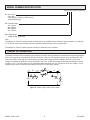
Control Concepts
Model 1022 / 1025
Power Control System
Instruction Manual
Another quality product from:
7128 Shady Oak Road
Eden Prairie, MN 55344 USA
(952) 949-9009 Fax (952) 949-9559
www.researchinc.com
CONTROL CONCEPTS, INC. 2 YEAR LIMITED WARRANTY
CONTROL CONCEPTS, INC. warrants that the products delivered will be as described in the sales order or contract.
CONTROL CONCEPTS, INC. warrants to the original user that CONTROL CONCEPTS, INC. products will be free from
defects in materials and workmanship for a period of two (2) years after the date CONTROL CONCEPTS, INC. ships
such products.
If any CONTROL CONCEPTS, INC. product is found to be defective in material or workmanship during the applicable
warranty period, CONTROL CONCEPTS, INC.’s entire liability, and purchasers sole and exclusive remedy, shall be the
repair or replacement of the defective product at CONTROL CONCEPTS, INC.’s election. CONTROL CONCEPTS,
INC. shall not be liable for any costs or expenses, whether direct or indirect, associated with the installation, removal or
re-installation of any defective product. All shipping and freight costs are the responsibility of the customer. CONTROL
CONCEPTS, INC.’s limited warranty shall not be effective or actionable unless there is compliance with all installation
and operating instructions furnished by CONTROL CONCEPTS, INC., or if the products have been modified or altered
without the written consent of CONTROL CONCEPTS, INC., or if such products have been subject to accident, misuse,
mishandling, tampering, negligence or improper maintenance. Any warranty claim must be submitted to CONTROL
CONCEPTS, INC. in writing within the stated warranty period.
CONTROL CONCEPTS, INC.’s limited warranty is made in lieu of, and CONTROL CONCEPTS, INC. disclaims all other
warranties, whether expressed or implied, including but not limited to any IMPLIED WARRANTY OF MERCHANTABILITY,
ANY IMPLIED WARRANTY OF FITNESS FOR A PARTICULAR PURPOSE, any implied warranty arising out of a course
of dealing or of performance, custom or usage of trade.
CONTROL CONCEPTS, INC. SHALL NOT, UNDER ANY CIRCUMSTANCES BE LIABLE FOR ANY DIRECT, INDIRECT,
INCIDENTAL, SPECIAL OR CONSEQUENTIAL DAMAGES (INCLUDING, BUT NOT LIMITED TO, LOSS OF PROFITS,
REVENUE OR BUSINESS) OR DAMAGE OR INJURY TO PERSONS OR PROPERTY IN ANY WAY RELATED TO
THE MANUFACTURE OR THE USE OF ITS PRODUCTS. The exclusion applies regardless of whether such damages
are sought based on breach of warranty, breach of contract, negligence, strict in tort, or any other legal theory, even if
CONTROL CONCEPTS, INC. has notice of the possibility of such damages.
By purchasing CONTROL CONCEPTS, INC.’s products, the purchaser agrees to the terms and conditions of this limited
warranty.
WARNING: The Control Concepts, Inc. power controllers use power thyristors to switch voltage to the connected
load. Line voltage must be assumed at the output terminals at all times, even when the control signal has been
removed and the load voltage appears to be off. It has been mandated by the National Electrical Code and the
Occupational Safety and Heath Act of 1970 that a physical disconnect be opened ahead of all remotely actuated
controls before performing any maintenance work on the controller or its connected load.
PROPRIETARY DATA
© Copyright 2007, Control Concepts, Inc. Chanhassen, MN 55317
The information and design disclosed herein are the property of Control Concepts, Inc. and may not be used,
reproduced or disclosed in any form except as granted in writing by:
CONTROL CONCEPTS, INC
7870 PARK DRIVE
CHANHASSEN, MN 55317
PHONE: (952) 474-6200
TOLL FREE: (800) 765-2799
FAX: (952) 474-6070
www.ccipower.com
MODEL 1022 & 1025 TABLE OF CONTENTS
DESCRIPTION
1
SPECIFICATIONS
1
INSTALLATION
2
INSTALLATION DRAWINGS
3
MODEL 1022 CONNECTIONS
5
MODEL 1025 CONNECTIONS
5
ZERO AND SPAN ADJUSTMENTS
6
RECOMMENDED SPARE PARTS AND FUSES
6
REFERENCE DRAWINGS
6
TROUBLE SHOOTING
7
MANUFACTURED BY
7
MODEL NUMBER IDENTIFICATION
8
THEORY OF OPERATION
8
MODEL 1022 & 1025
05/10/2007
DESCRIPTION
The models 1022 and 1025 are single-phase phase-angle SCR power controllers. The controllers are the same except
the 1022 accepts command signals of 0/5Vdc, 0/10Vdc or a potentiometer signal. The model 1025 accepts a 4/20mA
command signal.
Both controllers control the RMS voltage to the load proportional to the command signal, independent of line voltage
hanges. The controllers include soft-start and missing cycle detection which on power interruptions of one half cycle or
more sets the load voltage to zero and then increases the load voltage to the desired voltage at a predetermined rate.
his eliminates inrush currents that can occur due to loads with a low cold resistance or because of saturation when a
transformer is used between the controller and the load.
The command signal is electrically isolated from line and load voltages and all are electrically isolated from the heat sink.
SPECIFICATIONS
CONTROL MODE:
COMMAND SIGNAL:
Single-phase; Phase-angle; RMS value of the voltage applied to the load
Model 1022
Model 1025
SIGNAL
INPUT IMPEDANCE
0/5 Vdc
100K
0/10 Vdc
200K
Potentiometer
200K
(1K pot recommended, 20K permissible)
4/20 mA
200 Ohms
CONTROL RANGE:
6 to 97% of line voltage typical.
LINEARITY:
RMS load voltage is linear within 2% of span of the command signal.
ZERO AND SPAN
ADJUSTMENTS:
User adjustable over range of +/- 20% of span.
ISOLATION:
Dielectric strength input/line & load voltage/heatsink 4000V (RMS).
Insulation resistance input/line & load voltage/heatsink 10^10 ohms.
Maximum capacitance input to output 8pf.
COOLING:
Convection
MOUNTING:
Must be mounted on vertical surface with fins vertical. Unit may be mounted
adjacent to each other. Heatsink is electrically isolated.
LINE VOLTAGE:
120, 240, 480 or 575 Vac +10%, -20% 50/60 Hertz
DIAGNOSTIC INDICATOR:
The intensity of an LED varies as a function of the command signal. Feature
provides a quick and safe means to check controller operation.
PHYSICAL:
Weight:
Dimensions:
ENVIRONMENT:
Operating:
Storage:
Humidity:
DV/Dt AND TRANSIENT
VOLTAGE PROTECTION:
200 volts/usec minimum
A dv/dt snubber and a metal oxide varistor (MOV) are provided to protect against
high frequency transients (dv/dt) and voltage spikes.
DISSIPATION:
1.5 watt per amp of controlled current
RECOMMENDED FUSING:
Special semiconductor fuses are not required. It is advised that the controller and
load be protected with fast acting class ‘T’ fuses such as Bussmann type JJN (300V)
or JJS (600V) fuses. Control Concepts maintains an inventory of fuses and fuse
holders for your convenience. It is recommended that a fuse rated 120 to 125% of
maximum load current be selected.
MODEL 1022 & 1025
10 - 40 Amp 2 lbs
70 Amps 6 lbs
Refer to installation drawings.
0 to 55° C (32 to 131° F)
-40 to 80° C (-40 to 176° F)
0 to 95% Non-condensing
05/10/2007
SPECIFICATIONS (Continued)
SURGE CURRENT RATING
KW
Continuous
RMS rating
RMS 1
Second
Peak 1 Cycle
(Non-Repetive)
I^2 t rating
120 Vac
240 Vac
277 Vac
480 Vac
575 Vac
10
20
30
40
70
22
40
80
150
150
140
250
625
1000
1000
81
260
1620
4150
4150
1.20
2.40
3.60
4.80
8.40
2.40
4.80
7.20
9.60
16.80
2.77
5.54
8.31
11.08
19.39
4.80
9.60
14.40
19.20
33.60
5.75
11.50
17.25
23.00
40.25
INSTALLATION
The controller must be mounted on a vertical surface such that the heat radiating fins are vertical and located in an
environment that will not exceed 55°C and that is protected from dirt and dust.
The wiring must be per local electrical codes. The supply and load terminals will accept up to # 6 wire. The terminals for
the circuit transformer and control signals accept wire up to # 14. The terminals for the control signals and circuit
transformer are plug-in and may be removed by pulling perpendicular to the circuit card.
CAUTION:
1. The circuit transformer must be connected to the same supply as the controller and the load. A common installation
error has been that of the circuit transformer being powered from a different phase or being connected across the SCR
module rather than from the supply.
2. Do not over tighten the wire connections.
NOTE:
It is recommended that the controller and the load be protected with fast acting class "T" fuses such as described in the
specification portion or this instruction manual.
RECOMMENDED TIGHTENING TORQUE
USD CONNECTORS:
WIRE SIZE (AWG)
TORQUE
14 - 10 GA
8 GA
4 - 6 GA
2 - 3 GA
35 IN-LBS
40 IN-LBS
45 IN-LBS
50 IN-LBS
RECOMMENDED TIGHTENING TORQUE
FOR GREEN CONNECTOR:
WIRE SIZE (AWG)
TORQUE
12 TO 26GA
5.0 IN-LBS
MODEL 1022 & 1025
05/10/2007
INSTALLATION DRAWINGS
5.50
0.20 (4)
1.00
0.30
7.50
4.00
6.00
1.50
0.20 (4)
8.50
3.70
4.20
4.375
4.75
Figure 1. 10, 20, 30 & 40 Amp.
Figure 2. “-MO1” Mounting Option.
7.50
8.00
9.00
0.32 (4)
6.00
9.25
MODEL 1022 & 1025
Figure 3. 70 Amp.
05/10/2007
INSTALLATION DRAWINGS (Continued)
1.62
1.19
24 Vac
Secondary
2.00
120 or 240
Volt Primary
0.177 (2)
2.375
Figure 4. 120/240 Volt Primary Transformer.
2.99
2.50
0.245
0.375
H1
H2
H3
2.70
H4
1.75 2.50 3.25
X4
X2
X3
X1
2.99
0.44
0.22
Figure 5. 480 Volt across H1 and H4 of Primary.
Jumper across X2 & X3 to create 24 Vac on Secondary.
MODEL 1022 & 1025
05/10/2007
MODEL 1022 CONNECTIONS
CONTROL SIGNAL
CONNECTIONS
TO SUPPLY
LOAD
24
VAC
CW
POT
24
VAC
5
CCW
W
CW
24
VAC
0/10 Vdc
+
0/5 Vdc
+
W
CCW
5
CCW
W
CW
24
VAC
5
CCW
W
CW
TRANSFORMER
(NO PHASING REQUIRED)
MODEL 1025 CONNECTIONS
TO SUPPLY
LOAD
24
VAC
24
VAC
TRANSFORMER
(NO PHASING REQUIRED)
+
4/20 mA
MODEL 1022 & 1025
05/10/2007
ZERO AND SPAN ADJUSTMENTS
The zero and span adjustments have been factory adjusted to provide zero load voltage when the minimum command
signal is applied and to provide rated output voltage to the load when the maximum command signal is applied. Further
adjustment of these settings should not be required. If it is desired to readjust the zero and span settings the following
procedures should be followed.
Voltage and/or current measurements should be taken with meters that provide true RMS readings due to the chopped
waveforms provided by the SCR controller. Adjust the zero potentiometer with the minimum command signal applied such
that the load voltage is just zero. (Clockwise rotation of both the span and zero potentiometer increase the load voltage)
Adjust the span potentiometer with the maximum command signal applied such that load voltage equals the rated voltage
of the controller. It may be necessary to repeat these steps due to interaction that can occur.
NOTE The 1022 and 1025 controllers have line voltage compensation therefore if the supply voltage is above the nominal
rating the controller will supply the nominal rated voltage to the load.
For example, if a controller rated for 240 volt operation is supplied from a 260 volt supply and the maximum command
signal is applied the controller will supply only 240 volts to the load thereby eliminating the effects of line voltage changes.
RECOMMENDED SPARE PARTS AND FUSES
RECOMMENDED
REPLACEMENT SCR:
RECOMMENDED FUSES (typical)
(Alternative fuse size is 125% of maximum load current)
MODEL:
ASSEMBLY
PART No. *
CCI PART No.
BUSSMAN
PART No.
CCI
FUSEKIT **
1022-12-10 or 1025-12-10
1022-12-20 or 1025-12-20
1022-12-30 or 1025-12-30
1022-12-40 or 1025-12-40
1022-12-70 or 1025-12-70
1652-12-10
1652-12-20
1652-12-30
1652-12-40
1652-12-70
42110-0460-315
42110-0460-325
42110-0460-335
42110-0460-350
42110-0460-390
JJS-15
JJS-25
JJS-35
JJS-50
JJS-90
FK\62T15
FK\62T25
FK\62T35
FK\62T50
FK\62T90
1022-24-10 or 1025-24-10
1022-24-20 or 1025-24-20
1022-24-30 or 1025-24-30
1022-24-40 or 1025-24-40
1022-24-70 or 1025-24-70
1652-12-10
1652-12-20
1652-12-30
1652-12-40
1652-12-70
42110-0460-315
42110-0460-325
42110-0460-335
42110-0460-350
42110-0460-390
JJS-15
JJS-25
JJS-35
JJS-50
JJS-90
FK\62T15
FK\62T25
FK\62T35
FK\62T50
FK\62T90
1022-48-10 or 1025-48-10
1022-48-20 or 1025-48-20
1022-48-30 or 1025-48-30
1022-48-40 or 1025-48-40
1022-48-70 or 1025-48-70
1652-48-10
1652-48-20
1652-48-30
1652-48-40
1652-48-70
42110-0460-315
42110-0460-325
42110-0460-335
42110-0460-350
42110-0460-390
JJS-15
JJS-25
JJS-35
JJS-50
JJS-90
FK\62T15
FK\62T25
FK\62T35
FK\62T50
FK\62T90
* The assembly includes the SCR relay, a thermal conductive pad, an MOV and an instruction sheet.
** The fuse kit includes two fuses of appropriate rating for the frame size, and a fuseblock. Control concepts recommends
that fuses be rated at 120 to 125% of maximum load current.
REFERENCE DRAWINGS
Model 1022 Schematic:
Model 1025 Schematic:
B1000466
B1000324
Transformer Inst. Dwg.
AS1401
MODEL 1022 & 1025
05/10/2007
TROUBLE SHOOTING
CAUTION: High voltage exists on the supply and load terminals of this controller and may exist on other equipment
located near the controller. Use extreme caution to avoid electrical shock.
The LED located on the controller circuit can be used to aid in determining problems. This LED varies in intensity
proportional to the command signal and therefore should be proportional to the load voltage.
THE FOLLOWING ARE SYMPTOMS AND POSSIBLE CAUSES:
SYMPTOMS
POSSIBLE CAUSES
NO LOAD POWER, LED not ON:
Determine that the command sigal is applied to the
controller. Determine that 24 volts is applied to the circuit.
NO LOAD POWER, LED intensity can be varied:
Determine that all fuses are “OK”. If the voltage across the
SCR module is equal to the line voltage the SCR module
has probably failed. NOTE: If a replacement SCR module
is ordered specify the voltage and current rating of the
controller and the serial number of the failed unit.
LOAD POWER IS MAXIMUM AND CANNOT BE
REDUCED, LED is ON:
Determine that the command signal can be adjusted to
zero. Also remove the green plug-in connector to remove
the command signal. If the LED is not off, the circuit card
has failed.
LOAD POWER IS MAXIMUM AND CANNOT BE
REDUCED, LED is OFF:
Remove the 24Vac plug in connector. If the load still has
power the SCR module has probably failed as a short
allowing full power at be applied to the load. To determine
if the SCR module has shorted remove power and then
the line and load connections and measure the resistance
across the line and load terminals on the SCR module. If
the resistance is less than 10000 ohms the modual has
failed. NOTE: If a replacement SCR module is ordered
specify the voltage and current rating of the controller and
the serial number of the failed unit.
LOAD VOLTAGE SNAPS ON:
Determine that the primary of the circuit transformer is
connected to the same supply as the controller and load.
MAXIMUM LOAD VOLTAGE CANNOT BE OBTAINED:
Determine that the primary of the circuit transformer is
connected to the same supply as the controller and load.
Typically this problem is caused by the primary being
connected across the load and line connection at the
controller.
MANUFACTURED BY
7870 PARK DRIVE, CHANHASSEN, MN 55317
TEL: 952-474-6200
FAX: 952-474-6070
TOLL FREE: 800-765-2799
www.ccipower.com
U.S.A
MODEL 1022 & 1025
05/10/2007
MODEL NUMBER IDENTIFICATION
102X-VV-AA [-SCXXX] [-MOXX]
X = 2 for 1022,
5 for 1025
1022 (0/5Vdc, 0/10Vdc or POT control)
1025 (4/20mA input)
VV = Rated voltage:
12 = 120Vac
24 = 240Vac
48 = 480Vac
57 = 570Vac
AA = Rated amps:
10, 20, 30, 40, or 70 amps
Note:
The addition of "-SCXXX" implies that the controller has been modified to have a different input command. For example,
a "-SC1/5Vdc" implies the controller has been modified to operate with a 1/5Vdc control signal.
The addition of "-MOXX" implies a special mounting or assembly of the controller.
THEORY OF OPERATION
The model 1022 and 1025 are phase-angle controllers, therefore, the load voltage is controlled by turning the appropriate
SCR on for a portion of each electrical half cycle as shown in Figure 6. The waveform shown as EL represents the “ON”
time of the SCRs in each half cycle and therefore represents the voltage waveform applied to the load. As the load
voltage is increased the SCRs are turned ON earlier in the cycle. As the load voltage is decreased the SCRs are turned
on later in cycle. The load voltage can be varied with infinite resolution from 0 to 100 percent of the line voltage. Circuit
tolerances may limit the maximum load voltage to about 97% of the supply voltage.
Is
IL
Es
EL
L
O
A
D
Figure 6. Phase angle control at 50% power.
MODEL 1022 & 1025
05/10/2007