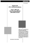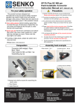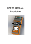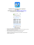
1
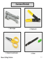
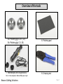
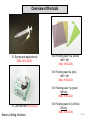
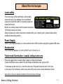
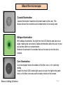
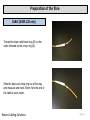
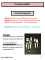
ANAEROBIC CONNECTOR
TERMINATION GUIDE
Nexans Cabling Solutions
Anaerobic OF toolkit: N102.230 – Revision C
Contents
Health and Safety recommendations
Overview of the tools
About the microscope
SC connector installation
SC connector components
Preparation of the fibre
Insertion into connector
Polishing (SC)
Final assembly (SC)
LC connector installation
LC connector components
Preparation of the fibre
Insertion into connector
Polishing (LC)
Final assembly (LC)
Nexans Cabling Solutions
page 2
page 3
page 7
page 9
page 9
page 10
page 12
page 20
page 26
page 27
page 27
page 28
page 32
page 38
page 44
Page 1
Health and Safety Requirements
Safe Handling
The broken ends of any fibre and the scraps of fibre created during termination (or splicing) are
potentially dangerous so must be handled with care at all times.
The ends are extremely sharp and can easily penetrate your skin or eyes . Once in your skin etc.,
scraps are almost impossible to find and therefore, their removal is very difficult.
• Do not pick up scrap pieces of fibre by their ends.
• You must properly dispose of all scraps using a dedicated container (as included in the toolkit).
• Do not drop fibre scraps on the floor where they could stick in carpets, shoes or cloths and be
later carried elsewhere - including home.
• Never eat or drink anywhere near the work area. Fibre scraps could get into food or drink
undetected and be swallowed.
Materials Safety
Fibre optic splicing and termination use various chemical cleaners and adhesives as part of the
processes. Correct handling procedures for these substances must be observed.
• If you are not certain of how to deal with them, ask the manufacturer for a MSDS (Material Safety
Data Sheet).
• Always work in well-ventilated areas.
• Even if safe to do so, avoid skin contact as much as possible and immediately stop using
chemicals that cause allergic reactions.
• Even simple isopropyl alcohol, used as a cleaner, is flammable and must be handled correctly.
Note
The above are basic safety requirements – your company, regional location or particular installation
requirements may specify additional requirements.
Nexans Cabling Solutions
Page 2
Overview of the tools
1. Cable stripper
2. Stripping tool
3. Scissors for aramid yarns
4. Scriber
Nexans Cabling Solutions
Page 3
Overview of the tools
5a. Polishing jig SC-ST (2.5)
5b. Polishing jig LC (1.25)
6. Polishing pad
7. Microscope (400x magnification)
8. Crimping tool
1.25, 2.5 mm adaptors / Micro-USB power input
Nexans Cabling Solutions
Page 4
Overview of the tools
9. Bottle for alcohol
10. Fibre scrap container
Storage of the adhesive & activator
- Optimal Storage: 8 °C to 21 °C.
- Storage below 8 °C or greater than 28 °C can
adversely affect product properties.
-Material removed from containers may be
contaminated during use. Do not return product
to the original container.
11a. Anaerobic adhesive
11b. Anaerobic activator
(N102.221)
Nexans Cabling Solutions
Page 5
Overview of the tools
12. Syringe and applicator tip
(50pc: N102.225)
13a. Polishing paper 12μ (yellow)
MM + SM
(10pc: N102.226)
13b. Polishing paper 3μ (pink)
MM + SM
(50pc: N102.223)
13c. Polishing paper 1μ (green)
MM only
(50pc: N102.222)
14. Lint free cloth (N102.224)
Nexans Cabling Solutions
13d. Polishing paper 0.3μ (White)
SM only
(50pc: N102.228)
Page 6
About the microscope
Laser safety
The microscope is fitted with filters, which greatly
reduce the risk of eye damage due to accidental
exposure to light from either an operating system or
visual fault locator.
Before use, always ensure that the system lasers are
‘Off’ before looking into a fibre.
Always observe eye safety procedures compliant with your company policy, relevant laser safety
standards and safety practice.
Power Supply
Either by AAA alkaline battery, or via the external micro-USB connector using the supplied USB cable..
Accessories
Fiber connector adaptors. 2.5 mm for SC/ST and 1.25 mm for LC.
Triple-mode illumination: coaxial, oblique and core
Press the toggle button to select either coaxial or oblique illumination.
Coaxial illumination uses a white LED and Oblique illumination uses a green LED.
To illuminate a patch lead core, insert the other end of the patch lead into the 2.5 mm hole
on the side of the instrument, which has a white LED, and use the coaxial illumination mode.
Also refer to the user manual included in the microscope soft case.
Nexans Cabling Solutions
Page 7
About the microscope
Coaxial illumination
Coaxial illumination maximizes the detail seen by the user. This
feature allows fine scratches and contamination to be easily seen.
Oblique illumination
With oblique illumination, the light from the LED hits the end-face at an
angle, making the core clearly visible and therefore allow the user to see
any surface debris or contamination.
However the amount of scratches that can be seen on the ferrule is
Limited.
Core illumination
Core illumination shows the details of the fiber core, or for continuity
testing.
It uses the inbuilt LED visible light source to inject the light to the patch
cord, so the fiber core area can be clearly shown on the screen.
Nexans Cabling Solutions
Page 8
SC connector installation
Also applicable for ST-connectors
SC connector components
N205.120: LANmark-OF SC Connector MM anaerobic 900µ & 2.8mm cable (1 piece)
N205.640bulk: LANmark-OF SC connectors MM anaerobic 900µm (100 pieces)
N205.645bulk: LANmark-OF SC Connector SM anaerobic 900µm (100 pieces)
A : Connector
B : Long Strain relief boot (*)
C : Connector shell
D : Crimp ring for 3mm cable (*)
E : Shrinkable cable label (*)
F : Large dust cap
G : Short Strain relief boot
(*): Only provided with N205.120
Nexans Cabling Solutions
A
B
C
D
E
F
G
Page 9
Preparation of the fibre
CABLE (N205.120 only)
Thread the strain relief boot long (B) on the
cable followed by the crimp ring (D).
Slide the boot and crimp ring out of the way
and measure and mark 35mm from the end of
the cable’s outer jacket.
Nexans Cabling Solutions
Page 10
Preparation of the fibre
Strip off the 35mm section of outer jacket with
the cable stripper tool (1).
Use scissors (3) to trim the aramid yarn flush
with the end of the outer jacket.
Nexans Cabling Solutions
Page 11
Preparation of the fibre
Measure and mark 6mm from the end of the
outer jacket.
Strip off the 6mm section of outer jacket so as to
expose 6mm of aramid yarns.
Nexans Cabling Solutions
Page 12
Preparation of the fibre
900µ BUFFERED FIBRE
Thread the short strain relief (G) onto the fibre.
CABLE AND FIBRE
Measure and mark 28mm from the end of the
fibre.
Remove 28mm of the buffer with the stripping
tool (2).
Nexans Cabling Solutions
Page 13
Insertion into the connector
Take a syringe (12) and fit the applicator tip.
Remove the plunger from the syringe body and
pour anaerobic adhesive into the body.
Replace the plunger and invert the syringe to
allow the air bubbles to escape.
Each time you inject a new connector, wipe the
needle tip clean to be sure that it is completely
free of adhesive. Insert the syringe tip into the
back end of the connector (A) until it seats.
Maintain pressure and slowly inject anaerobic
adhesive until a bead appears on the end of
the connector.
Nexans Cabling Solutions
Page 14
Insertion into the connector
Continue to inject adhesive until
the bead covers more than half of the ferrule’s
end face.
Release the pressure on the plunger
and withdraw the needle straight back.
DO NOT ALLOW ADHESIVE TO FILL THE
BACK OF THE CONNECTOR !!
Clean the fibre with a lint free cloth (14)
moistened with isopropyl alcohol (9) until the
fibre starts to squeak. Wipe straight towards the
fibre end.
Nexans Cabling Solutions
Page 15
Insertion into the connector
CABLE (N205.120 only)
Spread the aramid yarns to allow the connector
to slide over the entire exposed length of the
fibre.
Immerse the cleaned fibre in the activator (11b).
Avoid putting the aramid yarns in the
activator.
Nexans Cabling Solutions
Page 16
Insertion into the connector
CABLE (N205.120 only)
Slowly thread the connector straight onto the
fibre until the buffer seats at the base of the
ferrule.
Be sure to insert the fibre in the
connector within 10 seconds of dipping it into
the activator. Otherwise curing time will be
extended.
Slide the crimp ring (D) over the aramid yarns
and crimp it with the crimping tool (8).
-First step : crimp on the aramid yarns
(Use die 0.178”)
-Second step : crimp on the cable
(Use die 0.128”)
Nexans Cabling Solutions
Page 17
Insertion into the connector
CABLE AND FIBRE
After the connector has been fitted on the fibre,
put the connector safely aside to let the
adhesive cure for at least 1 minute.
The bead of glue is important to avoid breaking
the fibre inside the ferrule during the next step.
A large bead further reduces the risk of breaking
the fibre inside the connector .
CABLE AND FIBRE
Scoring the fibre.
Hold the connector in a vertical position with the
fibre pointing upward. Score the fibre with the
scriber (4) by drawing the scoring blade lightly
against it, just above the adhesive bead. The
fibre should merely be touched and not
severed. Detach the fibre by pulling and put it in
the fibre scrap container (10).
Be sure to dispose of all fiber ends per company practice
Nexans Cabling Solutions
Page 18
Insertion into the connector
CABLE (N205.120 only)
Push the boot onto the rear part of the
connector.
FIBRE
Push the boot onto the rear part of the
connector.
Nexans Cabling Solutions
Page 19
Polishing
Check the fibre end.
Polish the endface with the 12μ polishing paper
(13a yellow) (hold the paper in one hand, do not
place it on a surface yet, this in order to avoid
pressure on the tip of the connector).
Only polish the top part of the bead and proceed
to the next step.
Clean the polishing pad(6) with a lint free cloth
moistened with isopropyl alcohol (9). Wipe a
layer of alcohol onto the rubber pad.
Before the alcohol evaporates, place the 3μ
polishing paper (13a pink) on the polishing pad
shiny side down. The alcohol creates a suction
on the polishing paper and holds it in place.
Nexans Cabling Solutions
Page 20
Polishing
Preparation of the polishing jig for SC-ST
connector (5a).
Wipe the polishing surface of the polishing jig
with a lint-free cloth moistened with isopropyl
alcohol. You may blow the entire jig clean with
compressed air if necessary.
Push the ferrule into the jig until it stops.
Nexans Cabling Solutions
Page 21
Polishing
Gently place the jig with the connector in it on
the pink paper that is located on the polishing
pad.
The best practice is to place the edge of the jig
on the polishing paper and gently tilt it until the
complete surface of the jig touches the paper.
Remember the tip is a ragged glass end which
can easily be damaged.
Move the jig in a figure of eight pattern by
holding only the jig. The speed of your figure of
eights should be between one and two per
second.
Nexans Cabling Solutions
Page 22
Polishing
Once the fibre is supported by the epoxy bead,
begin applying light pressure on the connector
while polishing in a figure of eight motion.
Continue to polish on the 3μ polishing paper
until a thin layer of adhesive remains on the tip.
Stop when the outer edges of the epoxy layer
start to break up and feather.
Prepare to perform the 1μ (MM) or 0.3µ (SM) finish.
Using an isopropyl alcohol dampened lint-free
cloth, clean the ferrule, the polishing jig and 3μ
Polishing paper. Remove the 3μ polishing paper.
Clean the rubber pad. Wipe a layer of alcohol
onto the rubber pad.
Before the alcohol evaporates, place the 1μ or 0.3µ
polishing paper (13c: green / 13d: White) shiny side
down on the rubber pad. The alcohol creates a
suction on the polishing paper and holds it in place.
Nexans Cabling Solutions
Page 23
Polishing
Lightly polish until all the adhesive is removed
(15 to 20 figure of eights).
Before inspection with the microscope:
Using an isopropyl alcohol dampened lint-free
cloth, clean the ferrule.
During this process, gently push back the
ferrule: it should move back and then return to
its original position when the pressure is
released.
If the ferrule is not moving, the back of the
connector is glued and there is no recovery
possible: cut the connector and try again.
Place the SC-ST adapter on the microscope.
Insert the connector in the adapter.
Turn on the light and adjust the focus.
Nexans Cabling Solutions
Page 24
Polishing
Needs more polishing.
Some adhesive is still on the ferrule.
Good polishing result.
NO RECOVERY
POSSIBLE
Too much pressure when scribing.
Nexans Cabling Solutions
Fibre scribed too long and broke off
during polishing or too much
downward pressure during polishing.
Page 25
Final assembly
SC connector assembly
Once the SC connector has been mounted
and polished, the housing can be fitted onto
the body.
While holding the connector firmly by the boot,
align the chamfers on both the connector and
shell (C) and snap into place.
A positive click will be heard when the shell is
fully engaged.
Place the dust cap (F) on top of the connector
to protect the end face.
The connector is now assembled.
Nexans Cabling Solutions
Page 26
LC connector installation
LC connector components
N205.630: LANmark-OF LC Connector MM anaerobic 900µm (per piece)
N205.630bulk: LANmark-OF LC Connector MM Anaerobic 900µm (100 pieces)
N205.631: LC Connector MM anaerobic – 1.6 to 2.2mm cable (per piece)
N205.635bulk: LANmark-OF LC Connector SM anaerobic – 900µm (100 pieces)
900 µm coating
Each package contains an LC connector with
dust cap (D), and a short strain relief boot (E)
C
A
A
1.6 to 2.2mm cable (N205.631)
Each package contains an LC connector with
dust cap (A), a crimp ring for cable (B) and a
long strain relief boot (C)
B
D
B
E
Nexans Cabling Solutions
D
F
EC
G
Page 27
Preparation of the fibre
CABLE (N205.631 only)
Thread the strain relief boot long (C) on the
cable followed by the crimp ring (B).
Slide the boot and crimp ring out of the way
and measure and mark 35mm from the end of
the cable’s outer jacket.
Nexans Cabling Solutions
Page 28
Preparation of the fibre
CABLE (N205.631 only)
Strip off the 35mm section of outer jacket with
the cable stripper tool (1).
Use scissors (3) to trim the aramid yarn flush
with the end of the outer jacket.
Nexans Cabling Solutions
Page 29
Preparation of the fibre
CABLE (N205.631 only)
Measure and mark 6mm from the end of the
outer jacket.
Strip off the 6mm section of outer jacket so as to
expose 6mm of aramid yarns.
Nexans Cabling Solutions
Page 30
Preparation of the fibre
900µ BUFFERED FIBRE
Thread the short strain relief (E) onto the fibre.
CABLE AND FIBRE
Measure and mark 28mm from the end of the
fibre.
Remove 28mm of the buffer with the stripping
tool (2).
Nexans Cabling Solutions
Page 31
Insertion into the connector
Take a syringe (12) and fit the applicator tip.
Remove the plunger from the syringe body and
pour anaerobic adhesive into the body.
Replace the plunger and invert the syringe to
allow the air bubbles to escape.
Each time you inject a new connector, wipe the
needle tip clean to be sure that it is completely
free of adhesive. Insert the syringe tip into the
back end of the connector (A) until it seats.
Maintain pressure and slowly inject anaerobic
adhesive until a bead appears on the end of
the connector.
Nexans Cabling Solutions
Page 32
Insertion into the connector
Continue to inject adhesive until
the bead covers more than half of the ferrule’s
end face.
Note: SC picture – Also applicable to LC ferrule
Release the pressure on the plunger
and withdraw the needle straight back.
DO NOT ALLOW ADHESIVE TO FILL THE
BACK OF THE CONNECTOR !!
Clean the fibre with a lint free cloth (14)
moistened with isopropyl alcohol (9) until the
fibre starts to squeak. Wipe straight towards the
fibre end.
Nexans Cabling Solutions
Page 33
Insertion into the connector
CABLE (N205.631 only)
Spread the aramid yarns to allow the connector
to slide over the entire exposed length of the
fibre.
Immerse the cleaned fibre in the activator (11b).
Avoid putting the aramid yarns in the
activator.
Nexans Cabling Solutions
Page 34
Insertion into the connector
CABLE (N205.631 only)
Slowly thread the connector straight onto the
fibre until the buffer seats at the base of the
ferrule.
Be sure to insert the fibre in the
connector within 10 seconds of dipping it into
the activator. Otherwise curing time will be
extended.
Slide the crimp ring (B) over the aramid yarns
and crimp it with the crimping tool (8).
-First step : crimp on the aramid yarns
(Use die 0.128”)
-Second step : heat the shrinking tube until it fits
around the cable.
Nexans Cabling Solutions
Page 35
Insertion into the connector
CABLE AND FIBRE
After the connector has been fitted on the fibre,
put the connector safely aside to let the
adhesive cure for at least 1 minute.
The bead of glue is important to avoid breaking
the fibre inside the ferrule during the next step.
A large bead further reduces the risk of breaking
the fibre inside the connector .
Note: SC picture – Also applicable to LC ferrule
CABLE AND FIBRE
Scoring the fibre.
Hold the connector in a vertical position with the
fibre pointing upward. Score the fibre with the
scriber (4) by drawing the scoring blade lightly
against it, just above the adhesive bead. The
fibre should merely be touched and not
severed. Detach the fibre by pulling and put it in
the fibre scrap container (10).
Be sure to dispose of all fiber ends per company practice
Nexans Cabling Solutions
Page 36
Insertion into the connector
CABLE (N205.631 only)
Push the boot (C) onto the rear part of the
connector.
FIBRE
Push the boot onto the rear part of the
connector.
Nexans Cabling Solutions
Page 37
Polishing
Check the fibre end.
Polish the endface with the 12μ polishing paper
(13a yellow) (hold the paper in one hand, do not
place it on a surface yet, this in order to avoid
pressure on the tip of the connector).
Only polish the top part of the bead and proceed
to the next step.
Clean the polishing pad(6) with a lint free cloth
moistened with isopropyl alcohol (9). Wipe a
layer of alcohol onto the rubber pad.
Before the alcohol evaporates, place the 3μ
polishing paper (13a pink) on the polishing pad
shiny side down. The alcohol creates a suction
on the polishing paper and holds it in place.
Nexans Cabling Solutions
Page 38
Polishing
Preparation of the polishing jig for LC
connector (5b).
Wipe the polishing surface of the polishing jig
with a lint-free cloth moistened with isopropyl
alcohol. You may blow the entire jig clean with
compressed air if necessary.
Push the ferrule into the jig until it stops.
Nexans Cabling Solutions
Page 39
Polishing
Gently place the jig with the connector in it on
the pink paper that is located on the polishing
pad.
The best practice is to place the edge of the jig
on the polishing paper and gently tilt it until the
complete surface of the jig touches the paper.
Remember the tip is a ragged glass end which
can easily be damaged.
Move the jig in a figure of eight pattern by
holding only the jig. The speed of your figure of
eights should be between one and two per
Second.
Nexans Cabling Solutions
Page 40
Polishing
Once the fibre is supported by the epoxy bead,
begin applying light pressure on the connector
while polishing in a figure of eight motion.
Continue to polish on the 3μ polishing paper
until a thin layer of adhesive remains on the tip.
Note: SC picture – Also applicable to LC ferrule
Prepare to perform the 1μ (MM) or 0.3µ (SM) finish.
Using an isopropyl alcohol dampened lint-free
cloth, clean the ferrule, the polishing jig and 3μ
Polishing paper. Remove the 3μ polishing paper.
Clean the rubber pad. Wipe a layer of alcohol
onto the rubber pad.
Before the alcohol evaporates, place the 1μ or 0.3µ
polishing paper (13c: green / 13d: White) shiny side
down on the rubber pad. The alcohol creates a
suction on the polishing paper and holds it in place.
Nexans Cabling Solutions
Page 41
Polishing
Lightly polish until all the adhesive is removed
(15 to 20 figure of eights).
Note: SC picture – Also applicable to LC ferrule
Before inspection with the microscope:
Using an isopropyl alcohol dampened lint-free
cloth, clean the ferrule.
During this process, gently push back the
ferrule: it should move back and then return to
its original position when the pressure is
released.
If the ferrule is not moving, the back of the
connector is glued and there is no recovery
possible: cut the connector and try again.
Place the LC adapter on the microscope.
Insert the connector in the adapter.
Turn on the light and adjust the focus.
Nexans Cabling Solutions
Page 42
Polishing
Needs more polishing;
Some adhesive is still on the ferrule.
Good polishing result.
NO RECOVERY
POSSIBLE
Too much pressure when scribing.
Nexans Cabling Solutions
Fibre scribed too long and broke off
during polishing or too much
downward pressure during polishing.
Page 43
Final assembly
Place the dust cap on top of the connector to
protect the end face.
The connector is now assembled.
Nexans Cabling Solutions
Page 44
Global expert in cables and cabling systems
Nexans Cabling Solutions
Paris
rue Mozart, 4-10
92587 Clichy CEDEX
France
Tel +33 (0)1 56 69 84 00
Fax +33 (0)1 56 69 86 38
Brussels
Alsembergsesteenweg 2, b3
1501 Buizingen
Belgium
Tel +32 (0)2 363 38 00
Fax +32 (0)2 365 09 99
Basingstoke
2 Faraday Office Park
Faraday Road
Basingstoke• Hampshire RG24 8QQ • UK
Tel +44 (0) 1256 486640
Fax +44 (0) 1256 486650