1
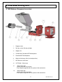
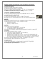
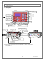
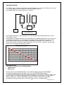
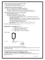
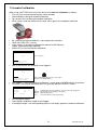
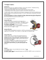
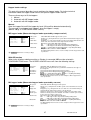
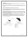
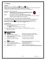
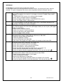
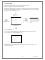
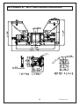
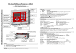
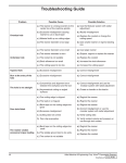
MC-TWIN
User Manual 1.4.UK.01
Software version
Manual revision
Date
:
:
:
V1.4
01
Maart 2008
1
MC-TWIN manual
INDEX
1. Introduction ______________________________________________________________________________________________ 3
1.1 Symbols_______________________________________________________________________________________________ 3
1.2 Terms ________________________________________________________________________________________________ 3
2. General information________________________________________________________________________________________ 4
2.1 Safety ________________________________________________________________________________________________ 4
2.2 Certification ____________________________________________________________________________________________ 4
2.3 Operating environmental conditions _________________________________________________________________________ 4
3. Overview Dosing unit ______________________________________________________________________________________ 5
3.1 MC-Balance Component overview __________________________________________________________________________ 5
3.2 Weighing frame _________________________________________________________________________________________ 6
3.3 Motor and dosing system _________________________________________________________________________________ 6
4. Metering principle _________________________________________________________________________________________ 7
5. Dosing systems / Capacities ________________________________________________________________________________ 8
6. Installation ______________________________________________________________________________________________ 10
6.1 Transport _____________________________________________________________________________________________ 10
6.2 Receipt ______________________________________________________________________________________________ 10
6.3 Mechanical Installation __________________________________________________________________________________ 10
6.4 Changing from Dosing cylinder to feed screw_________________________________________________________________ 11
6.5 Electrical installation ____________________________________________________________________________________ 12
7. Operation _______________________________________________________________________________________________ 14
7.1 Navigation ____________________________________________________________________________________________ 14
7.2 Start up ______________________________________________________________________________________________ 15
7.3 Login ________________________________________________________________________________________________ 15
7.4 Configuration __________________________________________________________________________________________ 16
7.5 Loadcell calibration _____________________________________________________________________________________ 21
7.6 Material Pre-calibration __________________________________________________________________________________ 22
7.7 Production ____________________________________________________________________________________________ 24
7.8 Hopper loaders ________________________________________________________________________________________ 26
7.9 Consumption __________________________________________________________________________________________ 29
7.10 Alarms ______________________________________________________________________________________________ 30
7.11 Files________________________________________________________________________________________________ 32
7.12 Select mode _________________________________________________________________________________________ 32
7.13 Material _____________________________________________________________________________________________ 32
7.14 Event LOG___________________________________________________________________________________________ 33
8. System performance ______________________________________________________________________________________ 34
8.1 Reset regulation _______________________________________________________________________________________ 34
9. Trouble shooting _________________________________________________________________________________________ 35
APPENDIX A:
MC-TWIN Print view _________________________________________________________________________ 36
APPENDIX B:
MC-TWIN Wiring Diagram ____________________________________________________________________ 37
APPENDIX C:
MC-TWIN Technical Specifications ____________________________________________________________ 38
APPENDIX D:
MC-TWIN General Dimensions ________________________________________________________________ 39
APPENDIX E:
MC-TWIN Declaration of Conformity ___________________________________________________________ 40
2
MC-TWIN manual
1. Introduction
Thank you for purchasing a Movacolor metering device. This manual is addressed to operators
and qualified technicians taking care of the metering of dry additives to ensure correct use of the
Movacolor dosing unit.
IMPORTANT NOTE: THIS MANUAL MUST BE READ BEFORE INSTALLING THE DOSING
UNIT. KEEP THIS MANUAL IN A PLACE ACCESSIBLE FOR ALL OPERATORS.
1.1 Symbols
Important note
Attention; safety regulations for the operator
1.2 Terms
Operator:
A person charged to operate, adjust, maintain and clean the machine.
Qualified Technician:
A specialized, suitable trained person authorized to execute the
installation, non-routine maintenance, or repairs requiring special
knowledge of the machine and how it operates.
3
MC-TWIN manual
2. General information
2.1 Safety
The equipment is only designed and may only be used for the dosing of dry additives.
Any use that is not in conformity with the instructions is considered improper and as such
frees the manufacturer from any liability regarding damage to things and/or persons.
Before switching on the unit for the first time, ensure that the mains power voltage
applied is between 80 and 260Vac.
Always switch off the Movacolor control cabinet and disconnect the mains power plug from
electrical power before performing maintenance.
Ensure that all parts are securely fixed to the extruder or injection molding machine.
Dangerous voltages are present inside the control cabinet for up to 2 minutes after it has
been switched off.
2.2 Certification
The Movacolor dosing unit is designed and produced in conformity with the following European
regulations:
•
standards for machinery (health, safety, environment)
• EMC (electromagnetic compatibility)
• VEM (safety electric material)
• 98/37/EC, Annex 1(See the declaration of conformity, Appendix E)
2.3 Operating environmental conditions
•
•
•
The unit must be protected against weather conditions
Operating temperature -20 to +70 degr. C.
Protection class: IP-50
4
MC-TWIN manual
3. Overview Dosing unit
3.1 MC-Balance Component overview
10
5
1
2
.
3
4
6
.
7
9
1
Stepper motor
2
Dosing system (Dosing cylinder)
3
Hopper 6 ltr
4
Curled knob Standard NST40 Neckpiece
5
Standard NST40 Neckpiece
6
Material discharge slide (in closed position)
7
MC-Balance Load frame
8
OPTIONAL Slide frame
8
9
Slide locking bolt
(locking the slide-out position)
Only supplied together with the optional slide mechanism
10
Slide locking bar
(locking the slide-in position)
Only supplied together with the optional slide mechanism
5
MC-TWIN manual
3.2 Weighing frame
Transport protection
Safety bolts (total of 4)
Hopper loader tube support
Balance frame
The black part is the weighing frame.
Do not touch this weighing frame (and dosing unit) while dosing.
It will have influence on the dosing.
Do not touch the safety bolts under the weighing platform. These are for overload protection.
There must be some space between de safety bolts and the frame.
3.3 Motor and dosing system
There are mainly two dosing systems, the dosing cylinder and the feed screw.
(for more information see chapter 5)
The serial number of the motor can be found on the
backside of the motor.
Motor axle:
The motor shaft is equipped with one flat side which
fits exact in shaft of the dosing cylinder.
To connect the dosing cylinder just put it on the
motor axle while turning it to find the flat side, than
press the dosing cylinder completely backwards.
6
MC-TWIN manual
4. Metering principle
The Dosing Cylinder® of Movacolor combined with a very precise adjustable stepper motor
ensures that the additive output is accurate and regular. The neckpiece (a mixing chamber) is
designed to blend the main material and the additive homogeneously. Movacolor has on stock a
large range of machine neckpieces that usually make a prefect fit to the injection molding machine
or extruder. The most common mounting of the neckpiece is between the production machine and
the hopper. In the figure below a cut through of the NST40 neckpiece can be seen.
Standard neckpiece
During operation, the virgin material runs from
the machine hopper through the neckpiece
into the machine. Inside the neckpiece the
Virgin material flow is divided into two
streams
by the cover plate. In the space below the
cover plate, the rotating cylinder is dosing
additive.
1
2
4
3
5
Additive is added directly into the center of
the virgin material flow, just before it enters
the production machine. This is a great
advantage over metering devices that use
batch pre-mixing because pre-mixing can
actually cause material separation.
Separation of materials results in an irregular
additive flow into the production machine.
6
Fig. 3
1. Color 2. Virgin material 3. Neckpiece 4. Dosing cylinder
4. Cover plate 5. Mixing zone 6. To production machine
7
MC-TWIN manual
5. Dosing systems / Capacities
Depending on the application a different dosing system might be needed.
Use the following table to determine roughly the best system for the application. For more detailed
information please contact your agent or Movacolor.
Dosing system
GLX
GX
HX
A-20
Feed screw
A-30
Feed screw ***
Note *
Note **
Note ***
Granular
materials
YES
YES
NO
YES
Powder
Materials
YES
YES
YES
YES
Accuracy
++
+
++
+/-
Dosing capacity
Gram/sec.
0,02 to 1,6*
0,2 to 5,0*
0,01 to 1,6**
0,5 to 20*
Dosing capacity
Kg/hour
0,07 to 5,8*
0,72 to 18,0*
0,04 to 5,8**
1,8 to 72*
YES
YES
+/-
2 to 50*
7,2 to 180*
measured with normal granular masterbatch 0,8 kg/dm3.
measured with free flowing powder 0,65 kg/dm3.
only available with high torque (4,5 Amp) stepper motor
Front side view
GLX
GX
HX
A20LT
A20HT
A30HT
Back side view
Which type of dosing system do I need with which neckpiece?
TYPE
GLX
GX
HX
A20LT
A20HT
A30HT
CODE FOR STANDARD NECKPIECE
GLX
GX
HX
A20
A20HT
A30
CODE FOR WATERCOOLED NECKPIECE
GLXC
GXC
HXC
A20C
A20HTC
A30C
8
MC-TWIN manual
All Movacolor dosing units are standard equipped with the stepper motor 2A (LT), in case of using
the feed screw A30 the stepper motor 4,5A (HT) will be supplied. Also a screw A20 can be
connected to the HT motor.
Stepper motor 2A
(LT)
Stepper motor 4,5A
(HT)
Do not select the HT motor if LT motor is connected. This will damage the motor.
If LT motor is selected and HT motor is connected there will be less motor torque and this can
influence the dosing.
The controller of the dosing unit makes a distinction between two groups of materials, normal
granules and micro granules. To determine the kind of material in your application use the
description below.
Material types
Normal Granules:
(NG)
ø
L
Ø<
Micro / Mini Granules:
(MG)
4 mm
L < 4 mm *
ø
L
The term Micro/Mini Granules also
includes free flowing powder.
Ø < ø2,5 mm L < 3 mm *
* For other sizes contact Movacolor.
The actual capacity of the dosing system depends on:
• The volume weight of the material (bulk density)
• The specific weight of the material (specific density)
• The granular shape of the material
• The granule size
• The surface structure of the material
Granular material can either be normal or micro. The granular material and powder material has to
be free flowing, non-static and not sticky.
9
MC-TWIN manual
6. Installation
6.1 Transport
To protect the Movacolor unit against damage during transport, the unit is packed in a cardboard
box filled with polyurethane foam. Delivery terms are Ex-Works Sneek, The Netherlands. Buyer is
responsible for the transport. Movacolor cannot be hold liable for any damage during transport.
6.2 Receipt
Check the unit thoroughly upon receipt. Pass any remarks to the local agent or Movacolor within 8
days upon receipt of goods.
6.3 Mechanical Installation
Most mechanical parts are pre-assembled, making installation quick and simple.
1. When installing a foreign main material
hopper on top of the neckpiece, the top
flange of the NST40 neckpiece need to be
adapted. The lid of the neckpiece can be
dismounted for easy machining.
Dismountable top
flange for easy
machining.
Take out the window in
a 45° angle for easy
cleaning.
2. -Install the neckpiece directly on top of the
entrance of the production machine.
-Install the neckpiece in a 90-degree angle
to the machine barrel. This will optimize the
dosing accuracy in relation to vibrations of
the production machine.
-Make sure that the complete unit is mounted
horizontally leveled and fixed securely.
-Assure proper grounding to control cabinet,
neckpiece and dosing unit
3. Remove the transport
protection (at the
bottom of the
loadframe) before
placing the hopper
assembly.
Transport
This is just the pin on
protection
the flexible chain, do
not dismount the stainless steel plate!
Curled knob
Main material
hopper
Hopper
assembly
4. Connect the hopper assembly to the
neckpiece by turning the curled knob
clockwise. Make sure that the curled knob is
tightened firmly.
Horizontally leveled
(Water leveled)
Barrel
5. Mount the controller vibration free and
conform specified temperatures.
90°
Install the neckpiece in a
90-degree angle to the
machine barrel.
As shown in the picture.
10
MC-TWIN manual
6.4 Changing from Dosing cylinder to feed screw
In relation to the maximum capacity of the dosing cylinder it might be necessary to change from
dosing cylinder to feed screw. As distinction from the dosing cylinder the feed screw system is
consisting of a rotating screw in a non-rotating tube.
3
1
2
4
To install the feed screw perform to following steps:
1. Detach the motor quick release clamps and take out the motor from the hopper.
2. Dismount the neckpiece connection flange (1) by removing 4 socket-head screws.
3. For use with a dosing cylinder the neckpiece connection flange (1) is equipped with a ball
bearing. When using a feed screw system the ball bearing must be taken out. The metal ring
(2) which is fixed on the feed screw tube fits directly on the neckpiece connection flange.
4. Dismount the dosing cylinder (3) and mount the screw (4) with the M5 bolt.
5. Place back the motor + screw by closing the motor quick release clamps.
For cleaning the motor + screw can be easily be taken out.
POSSIBLE COMBINATIONS
A20
GX / GLX / HX
Art.nr:H000002
Art.nr:H000014
Included ball bearing
G / GL / H
Art.nr:H000010
Included seal
11
MC-TWIN manual
BALL BEARING
For cleaning of the ball bearing use a dry piece of textile or a smooth dry toothbrush to remove
the dust or moisture and foreign particles that stick.
Following points have effect on the lifetime of the ball bearing:
o Abrasive materials
o Temperature
o Dusty / fine powder materials
6.5 Electrical installation
The MC-TWIN controller is standard equipped with following connections:
• Mains power cable
Before switching on the unit for the first time, ensure the mains power voltage being
applied is between 80 and 260Vac.
• Input cable
• 2 Motor cables, 1 for Regrind and 1 for Color
• 2 Load cell connectors, 1 for Regrind and 1 for Color
• Network connection
• 1 controller with display (Regrind unit) and 1 controller with blind lid (Color unit)
• Compressed air solenoid valve complete with cable for automatic hopper loader (Regrind)
Optional are:
• Alarm flash light, complete with cable
• Compressed air solenoid valve complete with cable for automatic hopper loader Color
12
MC-TWIN manual
APPENDIX A SHOWS THE PRINT VIEW WHICH WILL BE EXPLAINED BELOW
1) PROCESSOR BOARD
The processor board is the heart of the controller.
This board must be fixed securely on the mainboard.
There’s also a label on it with the Mac-address. This is the ID of the networkcard.
This address can also be seen in the startup screen.
The TWIN has two main boards inside. (1 for the Regrind and 1 for the Color)
2) EXTERNAL TERMINAL CONNECTION
This connector will be used for the remote terminal (Shielded cable max. 10 meter)
3) CONNECTION TO PC OR NETWORK
This connection (Ethernet) will be used when using a PC or network.
Max. length of the UTP network cable (Cat. 5) is 100 meter between 2 network points.
4) INPUTS
Start input
The MC-TWIN needs an input signal from the production machine in order to operate.
Two different input signals can be used to control the MC-TWIN:
• Potential free start input.
• Potential (18-30Vdc) start input
5) MOTOR
The MC-TWIN can control 2 motor types:
• LT (low torque) standard motor for normal dosing
• HT (high torque) motor for high output dosing
(See chapter 5 for more details and wiring diagram for electrical connections, appendix B)
6) OUTPUTS
The MC-TWIN has following outputs available:
• Valve output for hopper loader (Solid state 24VDC/0.5 A)
• Warning output (Solid state 24VDC/0.5 A)
• Potential free relay (normally open) output for alarm level (max. 230Vac/30Vdc, 5A)
• Potential free relay (normally open) output for running contact (max. 230Vac/30Vdc, 5A)
This contact will be closed simultaneously when the motor of the dosing unit is running.
The maximum total output power may be 12 Watt (Valve output + alarm output)
(See wiring diagram appendix B for electrical connections)
7) POWER SUPPLY
The MC-TWIN will operate with a voltage from 80 VAC to 260 VAC, 50 and 60 Hz
by integrated automatic voltage selector.
(See wiring diagram appendix B for electrical connections)
13
MC-TWIN manual
7. Operation
7.1 Navigation
Alphanumerical buttons:
Set values / descriptions
Input LED is lighted:
input signal is ON
Enter:
Confirm settings
Alarm LED is lighted:
alarm / warning
Stop:
Stop unit
Arrow left / right:
Scroll through menus /
settings
Start:
Start unit
Enter / scroll / exit MENU
Arrow up / down:
Scroll through parameters
Start input cable
Load cell
Start LED blinking:
motor is stand by / waiting for start signal
Start LED lighted:
motor is running
Mains power switch: ON / OFF
Mains power cable
External communication /
Network
REGRIND
UNIT
RJ45
Crossed
UTP cable
COLOR
UNIT
Valve output
for hopper loader
Output for:
-Alarm
-Warning
-Running
Motor cable
Note that from the color unit the internal dipswitch 1 = ON on the mainboard.
(see appendix A)
14
MC-TWIN manual
7.2 Start up
Directly after switching on the mains power of the MC-TWIN, the software versions will be
displayed.
In the first screen the software version of the terminal will be shown.
Movacolor Terminal
Version x.xx
Date: January 2005
After a few seconds the second screen appears
REGRIND MODE
Color in Control
Twin Vx.x
DE-Vx.x
MENU to continue
BL Vx.x
Mac-00:12:EC:xx:xx:xx
TWIN Vx.x = TWIN user software version Vx.x
DE-Vx.x = Language version Vx.x
Standard language is English
DE means that the additional language is DEUTSCH (German).
BL Vx.x = bootloader software (firmware) Vx.x
Mac address = ID address of the network card
7.3 Login
The MC-Twin controller has three user levels:
1. Operator
2. Tooling
3. Supervisor
The functions which are accessible per user level is shown in the table below.
The operator level is the lowest level, only the important settings for production can be done. The
rest of the settings / menu’s are invisible or locked.
For changing to another user level, enter the LOGIN menu and enter the password (4 numerals)
and confirm. The passwords for the Tooling and Supervisor user levels can be defined by the
supervisor in the CONFIGURATION <menu>.
USER LEVEL
Can be changed in LOGIN menu.
MENU TITLE:
FUNCTION:
[LOGIN]
[CONFIGURATION]
[PRODUCTION]
To enter the different user levels.
To configure the dosing system.
To do the production settings.
*In OPERATOR level materials are read only.
To look for, rename or delete material curves
To do the hopper loader settings,
only visible when a hopper loader is selected.
To make material calibrations, only visible when control
mode is set to GRAVI (Gravimetric).
To calibrate the load cell.
To check the hopper or object weight.
View of the total quantity of material dosed by the
MC-Balance.
View of the alarm history
*In TOOLING level the alarm configuration is invisible.
The history of events or settings will be logged in this menu.
To select the Color- or Regrind dosing unit.
To select a material curve.
[FILES]
[HOPPER LOADER]
[CALIBRATION]
[LOAD CELL]
[WEIGHT CHECK]
[CONSUMPTION]
[ALARMS]
[EVENT LOG]
[SELECT MODE]
[MATERIAL]
SUPERVISOR
Default code
2222
TOOLING
Default code
1111
OPERATOR
Default code
0000
YES
YES
YES
YES
NO
NO
YES
YES
YES*
YES
NO
NO
YES
YES
YES
YES
YES
NO
YES
NO
NO
YES
YES
NO
YES
YES
NO
YES
YES*
NO
YES
NO
NO
YES
YES
NO
YES
YES
NO
Recommended to note the passwords!
Forgot your supervisor password, enter the overall supervisor password 1689.
When entering a wrong password the user level will be set automatically to operator level.
15
MC-TWIN manual
7.4 Configuration
For initial setup the MC-TWIN controller needs to be configured in the CONFIGURATION menu
once. Depending on the configuration, some settings will be invisible in case they are not relevant.
Highlighted Parameters are factory settings.
Motor type
Cylinder type
Material type
Cal dev.
Input mode
Input filter
: LT / HT
: G / GL / H / A20 / A30 / GL / GLX
: NORMAL / MICRO
: 5,0 %
: Timer / Relay
: (1-32)
Fill. System
: NO / ME / MV/ GR
Filling start
Hopper empty
Regrind HL
Regrind lvl4
Deviationalarm
Auto start
Master reset
IP
Name
Start user
Tooling passw.
Supervisor passw.
Date
Time
: 800 gr.
: 700 gr.
: 2000 gr.
: 20% (0-80%)
: 25 %
: NO / YES
: NONE / ALARM / MATER / ALL
: xxx . xxx . xxx . xxx
: xxxxxxxxxxxxxx
: Operator / Tooling / Supervisor
: xxxx 1111
: xxxx 2222
: (dd / mm / yy)
: (hh / mm / ss)
(not visible in Color mode)
(not visible in Color mode,
only with relay selection)
(GR only in Regrind mode)
(MV only in Color mode)
(only with ME or MV)
(only with ME / MV / NO)
(only when GR selected)
(only when GR selected)
(not visible in Color mode)
(not visible in Color mode)
(not visible in Color mode)
(not visible in Color mode)
(not visible in Color mode)
(not visible in Color mode)
(not visible in Color mode)
Configuration: Language
Standard language is English. On request also different languages are available.
Configuration: Motor type
LT is Low Torque motor and HT is High Torque motor (see chapter 5 for more information)
Do not select HT motor if LT motor is connected.
Configuration: Cylinder type
Type of dosing cylinder / feed screw (see chapter 5 for more information)
Configuration: Material type
Type of material, normal granules (NORMAL) and micro granules (MICRO).
(see chapter 5 for more information)
Configuration: Cal dev.
The maximum allowed deviation from the Calibration Setpoint can be set with this
Parameter. (For more information see chapter 7.6)
Configuration: Input mode
Type of input signal. Relay, Timer
timer
relay
INJ
x
x
x
GRAVI RPM
Input mode is not visible in RPM prod. Mode. (Timer is used automatically)
16
MC-TWIN manual
Input (start) signal
The MC-TWIN needs an input signal from the production machine in order to operate.
Three different input signals can be used to control the MC-TWIN.
1.)
A potential free relay contact.
Use the white and brown wire for the potential free contact.
2.)
A relay signal up to 30 Volt DC.
In case of a powered relay signal connect the white wire to +24 VDC and the yellow wire to
the - side.
To detect a start signal the MC-TWIN needs a minimum voltage of 18VDC.
Configuration: Input filter
After this number of cycles(1-32) the relay signal is steady.
Standard the input filter is set to 3.
Only visible in relay mode.
Configuration: Fill. System
Filling system, NO(None), ME, MV or GR (see chapter 7.7)
Configuration: Filling start
Function: When it is detected that the hopper is running empty the filling system will switch on.
The filling system will start loading when the weight in the hopper is 800 grams (default) or less.
The default value can be changed manual if necessary (depending on the material properties).
Only visible when a filling system is selected.
Configuration: Hopper empty
The system will give an “Low hopper level” message if there is less then 700 (default) grams of
material in the hopper. For this system to work correctly it is necessary that the load cell calibration
is done with an empty hopper and the hopper lid in place. This system will always be active.
The default value can be changed manual if necessary (depending on the material properties).
Regrind HL
High level of the Regrind hopper. This is the weight in the Regrind hopper when the hopper is
maximum filled. (default is 2000gr.)
Regrind lvl4
Maximum Regrind dosing percentage (Level 4 of the Regrind hopper). This value will be added to
the Regrind % setting in Production screen. (default is 20%)
Configuration: Deviationalarm
Setting for the “Maximum deviation exceeded” message.
The MC-Balance automatically adjusts his motor speed to the desired setpoint. The controller is
able to detect and alarm when the setpoint is not reached within a set percentage. If after the
normal performed speed adjustments the setpoint is consistently not reached, the controller will
give an alarm signal and message in the display.
If the setpoint it not reached within the set percentage this can be caused by:
- Partial or complete blockage by sticky or hard flowing material.
- Inaccurate dosing because material is not uniform in size.
- Disturbance of the weight signal, for example by mechanical blocking of the MC-Balance loadframe.
The Maximum deviation setting can be set in the CONFIGURATION menu:
Deviationalarm:
xx% (1-99%)
17
MC-TWIN manual
Output [gram/sec]
+ limit :
Setpoint [gram/sec.]
maximum deviation % setting
- limit :
Time
Example:
The Deviationalarm setting in the configuration menu is default set to 25%
The set point (color set) is set to
: 1,000 gr/sec
-the MAXIMUM limit value will be
: 1,250 gr/sec
-the MINIMUM limit value will be
: 0,750 gr/sec
When the maximum deviation message (Error 01, page 33) appears in the display of the controller it shows the measured deviation in
percentage of the setpoint.
Configuration: Auto start
Enable / disable auto startup after Voltage dip or mains power has been switched OFF.
When enabled the unit will continue dosing automatically after a Voltage dip or mains power has
been switched OFF.
Configuration: Master reset
Reset alarm history (ALARMS). All alarm/warning messages saved in the alarm history will be
Removed.
Reset material calibrations (MATER.) All material calibrations will be removed.
Reset these three together (ALL). Alarm history, material curves will be removed.
Configuration: IP
IP-address for use in a network environment (TCP/IP protocol).
When a MC-TWIN is part of a network, the controller must have an IP-address for identification.
The IP address has to be filled in for communication between the Regrind and the Color dosing
unit. In the Regrind mode the IP-address can be entered. Standard the IP-address of the Color unit
will be one number higher (after entering the IP-address switch OFF and ON the controller)
Ask your network administrator for a unique address.
Configuration: Name
Give a name or figures for individual identification (for use in network).
For example the name of the Regrind and Color dosing unit.
Configuration: Start user
User level to start up with, when switching on the controller’s mains power.
Operator, Tooling or Supervisor.
Configuration: Tooling passw.
Password for Tooling user level, 4 numerals, default 1111
Configuration: Supervisor passw.
Password for Supervisor user level 4 numerals default 2222
Configuration: Date
Actual date (dd / mm / yy)
Configuration: Time
Actual time (hh / mm / ss)
18
MC-TWIN manual
TWIN REGULATION
The TWIN system functions as two Balances with Regrind unit as master and Color unit as slave.
It is only possible to use the TWIN on an Injection molding machine.
In the figure below the schematic process is viewed.
Virgin
4
3
2
Regrind
Color
1
0
Neckpiece
Grinder
Inj. Moulding machine
In the diagram below the relation between the Color dosing and the Regrind dosing is shown.
This relation is linear.
Consequently, the regrind metering unit also determines the MB dosing amount at the same time.
To regulate the overall mix, it is convenient if the regrind metering unit knows in advance how
much regrind needs to be processed before the MB dose is adjusted. This is done via a
master-slave control in which the regrind metering unit is the master. In practice, the metering
unit(s) will try to achieve the optimum set point.
% of Masterbatch to add to make 100% color
in relation to % regrind to be added
(on the basis that regrind contains same color % as final product)
3,0%
3,0%
% of masterbatch added to make 100% color
2,7%
2,4%
2,5%
2,1%
2,0%
1,8%
1,5%
1,5%
1,2%
0,9%
1,0%
0,6%
0,5%
0,3%
0,0%
0%
10
%
90
%
80
%
70
%
60
%
50
%
40
%
30
%
20
%
10
0%
0,0%
% of regrind
TWIN OPERATION
The TWIN has the following two dosing modes:
• Regrind mode
• Color mode
The unit starts up in de Regrind mode. In this mode the dosing can be started/stopped.
The Regrind configuration can be done here also in CONFIGURATION <menu>.
To switch from the Regrind to the Color mode and opposite, enter SELECT MODE <menu> and
select YES/NO. In the Color mode all the Color configurations can be done, also per mode a
material calibration / selection (MATERIAL <menu>), load cell calibration can be done.
All production settings can be done in PRODUCTION <menu> in Regrind mode.
MC-TWIN manual
19
There are basically two ways to operate with the TWIN:
1. Without Grinder connected to the machine.
2. With Grinder connected to the machine (closed loop)
*1 Without Grinder connected to the machine.
If no Grinder is connected and use storage bins to load Regrind:
• Select ME as hopper loader in CONFIGURATION menu.
• The filling of the hopper will work like a normal ME hopper loader system.
• The Regrind system will dose to the Regrind% Setpoint set in Production menu.
*2 With Grinder connected to the machine (closed loop).
• Go to CONFIGURATION menu
• Select GR as hopper loader for Grinder settings
• The following two additional settings will be visible:
o HL = High level of the Regrind hopper. This is the total weight of material if the
hopper is maximum filled.
For example the bulk density of used Regrind = 0,6 kg/dm3 * 6 dm3 hopper = 3600
gram or go to weight check menu, reset the weight and fill the hopper to maximum
and read the object weight and fill this in as HL.
o Lvl4 = Maximum Regrind dosing percentage.
This value will be added to the Regrind % setting in Production screen.
(default is 20%)
For example the Regrind % to be added is 20%, then the max Regrind% is 40% with the default value of Lvl4 is 20%.
If this value is set to 0%, the maximum Regrind % will be 20%
The Regrind hopper is divided in 5 weight levels:
Regrind% level
0: 0% Regrind
1: % Regrind medium Level 0 and Level 2
2: % Regrind set in Production screen
3: % Regrind medium Level 2 and Level 4
4: % Regrind level 2 + Lvl4 (=max. Regrind %)
Regrind hopper
4
3
Regrind
2
1
0
For example
Regrind% set in Production screen is 20%
Lvl4 is set to 20%
Regrind% level
0: 0% Regrind
1: 10% Regrind
2: 20% Regrind
3: 30% Regrind
4: 40% Regrind
The values of level 1 and 3 will be automatically calculated.
Based upon the amount of regrind present in the regrind hopper the dosing level of the color unit is
automatically adjusted.
When the Regrind hopper is empty (below Level 1) only the Color will be dosed at the set Color%.
The hopper loader will fill with intervals fill offtime 2 (fast filling).
The Regrind unit starts dosing if the Level is between level 2 and 3.
The hopper loader will fill now with intervals fill offtime 1 (normal operation)
If the regrind weight comes above level 4, filling of the hopper will stop until the weight is again
between level 2 and 3.
20
MC-TWIN manual
7.5 Loadcell calibration
When using a MC-TWIN for the first time do an initial load cell calibration as follows:
• The unit must be mounted horizontally (water leveled)
• Avoid vibrations during the loadcell calibration.
• Do not touch the unit during the loadcell calibration.
• When using a slide the whole unit has to be slid in against the neckpiece and fixed.
•
•
•
•
Be sure that the Balance load cell is connected to the controller
Go to the LOAD CELL <menu>
In this menu it is possible to calibrate the load cell of MC-Balance
(500gr. Calibration weight required)
Select YES to start the load cell calibration
LOADCELL CALIBRATION
[***]
[***] = Progress
Status
Calibration busy.
Please wait…………..
•
After a few minutes the following screen appears:
LOADCELL CALIBRATION
[***]
Status
Place weight, press
START when ready.
•
•
Place calibration weight (500 gr.) on the hopper
and press the START button
After approx. 1 minute the load cell calibration is ready, press the MENU button to continue.
To check if the load cell calibration was OK, go to the WEIGHT CHECK <menu>
WEIGHT CHECK
Weight:
Object:
Zero:
•
•
•
gr.
gr.
NO/YES
><
><:
Weight:
Object:
Zero:
Standstill sign. When the vibrations are too big, this sign disappears!
Actual weight on the weighing scale (gram)
Object weight (gram)
Zero YES / NO. Reset the object weight.
Zero the object weight
Place 500 gr. calibration weight on the Hopper
If the object weight is not corresponding with the real weight, perform a load cell calibration.
21
MC-TWIN manual
7.6 Material Pre-calibration
The MC-Balance mainly can be started in two ways:
1) Start the unit without pre-calibration of material.
After pressing the START button the unit starts dosing on a speed that is based on default curves
which are pre-programmed in the controller. After start up the unit continues with self calibrating to
the Setpoint.
2) Start the unit with pre-calibration of material (OFF-LINE).
After pressing the START button the unit starts dosing on a speed that is based on material
calibrations made by the user which are stored in the controller. After start up the unit continues
with fine tuning to the Setpoint.
What is the function of a material Pre-calibration ?
With a pre-calibration it is possible to calibrate the unit before production is started, in this way the
time needed to come in spec. can be reduced. The MC-Balance is a gravimetric / loss in weight
dosing unit. When starting up the dosing unit for a new production run there is no direct information
available about the loss in weight. Of course you want the dosing unit to reach his setpoint with the
matching speed of the motor (RPM) as quick as possible. Starting the unit with a speed that is
already most near to the set point will achieve quick regulation. The correct RPM at the start of the
dosing unit can be determined automatically with a pre-calibration.
The pre-calibration can be done in two ways (see below)
1) Unit with option slide frame:
Slide the frame with unit backwards till the “click”
•
•
•
2) Unit without optional slide mechanism:
Take out the dosing unit and put it on the frame like shown
It is important that during calibration the dosing unit is mounted fixed and horizontally and also
vibration free.
Before starting a material calibration be sure the hopper is filled with material sufficient.
Be sure that the loadcell cable is connected to the MC-Balance controller.
Following parameters will be stored with a Material calibration, depending on the configuration:
• CONFIGURATION parameters:
Cylinder type : type of dosing cylinder or feed screw
Material Type : Normal or micro-granules
• PRODUCTION parameters:
Shotwth.
: Shot weight
color%
: Color amount (%)
dos.time
: Dosing time (sec)
Ext. cap.
: Extruder capacity (kg/h)
• CALIBRATION parameters:
Material name : Name of calibrated material
22
MC-TWIN manual
How to make a material calibration?
• Go to the CALIBRATION menu.
• Enter Material name and your production parameters.
• Start calibrating. The following screen appears:
CALIBRATION
[TESTING BUSY]
[*****]
Set
: 1,000 gr/s
Actual : 0,945 gr/s
Stop & Store : YES/NO
•
•
•
The calibration will take minimal about 3 minutes but can take more time depending on the
used material and production parameters.
It is possible to stop during the calibration (for example to refill the hopper).
To continue select YES and confirm. To stop select NO and confirm.
The calibration will automatically be finished and saved after the Setpoint is reached within the
set calibration deviation (Cal dev: default = 5%) set in configurations menu. (see chapter 7.4)
After saving you will automatically go to the PRODUCTION menu and stored calibration is
automatically selected.
Stored material curves have a * after the filename.
During the calibration the unit is regulating to his Setpoint. When this point is reached the
calibration will be saved automatically. On the basis of this point a complete curve is made on
bases of default pre-programmed curves.
Material Calibration
Single point calibration on basis of preprogrammed MOVA-curve
How can I select a calibrated material?
When one or more material calibrations are made, one of these can be selected as follows:
• Go to MATERIAL <menu>
• Press the <enter> button for 2 seconds
A list will appear with stored material calibrations
• Select one with arrow buttons and confirm
If the material calibration made is not in the list fill in the first letter(s) and confirm. Now a filtered list
appears. To go back to the main list fill in spaces and confirm.
It is also possible to fill in the material description immediately in the PRODUCTION <menu> and
confirm. The message “Material not found, select new material” appears when a false material
is filled in. To clear the material description fill in spaces or select an empty material calibration out
of the list.
How can I delete or rename a calibrated material?
To delete one or more material see chapter 7.11.
To delete all Materials select master reset MATERIAL in the CONFIGURATIONS <menu> and
confirm.
23
MC-TWIN manual
7.7 Production
The rotation direction of the dosing at the front view must be to the right
Production (Motor On/Off)
Press the start button to start dosing. (only possible in Regrind mode)
The start LED blinks when the unit is waiting for an input signal.
The unit is dosing if the Start LED lights continuously.
When the unit is started the actual production data will be shown.
Press the stop button to stop production.
Please notice that it is possible that the first dosing(s) are not sufficient, because of the cylinder filling with material.
It takes some time to stabilize.
3 levels of production screens:
The unit will switch automatically to the STATUS screen.
PRODUCTION SETTINGS
Color % :
Regrind %:
Shot wth.:
Dos.time :
Test
:
STATUS
%
%
gr
s
NO/YES
COLOR
REGRIND
x.xxx%
x.xxx%
CAL/OK
CAL/OK
Set:
Act:
Wth:
Tim:
RPM:
Sts:
PRODUCTION DATA
REGRIND COLOR
x.xxx
x.xxx
x.xxx
*****
xxx><
xxx><
x.x
x.x
x.x
*Std.by
gr/s
gr/s
gr
sec
rpm
Std.by*
The status switches from “CAL” =
CALIBRATING to “OK” when the
deviation between set output and
actual output is less than 10%
(Menu Button)
INJECTION MOULDING
The following parameters can be seen in the production screen, depending on operation or
settings (made in supervisor mode):
Injection molding / Gravimetric mode
Production Settings
PRODUCTION SETTINGS
Color % :
%
Regrind %:
%
Shot wth.:
gr
Dos.time :
s
Test
:
NO/YES
Color % : Color amount (%)
Regrind%: Regrind amount (%)
(0-80%)
Shot wth : Shot weight (gr.)
Dos. time : Dosing time (sec.)
Dosing time only visible in Timer mode
Test:
: initial production test with set speed and time
Actual production data
Set:
Act:
Wth:
Tim:
RPM:
Sts:
PRODUCTION DATA
REGRIND COLOR
x.xxx
x.xxx gr/s
x.xxx
***** gr/s
xxx><
xxx>< gr
x.x
sec
x.x
x.x
rpm
*Std.by *Std.by
Set.
Act.
Wth.
><
Tim
RPM
Sts
*
: Calculated output (gr/sec)
: Actual color output (gr/sec)
actual color output is only visible after the first automatic RPM adjustment.
If there’s not yet a value known *** will be displayed
: Material weight in the hopper
: Standstill sign. When the vibrations are too big, this sign disappears!
: count down of the actual dosing time (sec)
: Actual motor speed (RPM)
: Status of the dosing, Standby / dosing / filling
: Actual value is a theoretical value.
Disappears after the first gravimetrical measurement
24
MC-TWIN manual
How can I select a calibrated material?
When one or more material calibrations are made, one of these can be selected as follows:
• Go to MATERIAL <menu>
• Press 2 seconds on the <enter> button
A list (max 10 ) will appear with stored material calibrations
(The materials with a * after their names are multi point calibrations)
• Select one with arrow buttons and confirm
If the material calibration made is not in the list (because of max. 10 in the screen) fill in the first
letter(s) and confirm. Now a filtered list appears.
To go back to the main list fill in spaces and confirm.
To clear the material description fill in spaces or select an empty material calibration out of the list.
How can I delete a calibrated material?
For deleting one or more materials see chapter 7.10
For deleting all materials select master reset MATERIAL in the CONFIGURATIONS <menu> and
confirm.
Test function
With the test function both units will dose material with the set dosing time and set / calculated
speed.
Do a test as follows:
• Go to PRODUCTION <menu>
• Fill in the production settings
• Use the arrow buttons to go to Test
• Select YES and confirm .
• The unit will run with the set parameters.
It is possible to stop the test with the stop button.
25
MC-TWIN manual
7.8 Hopper loaders
Introduction
Movacolor dosing units are capable of handling a variety of dry materials. Two different filling
systems are available depending on the material properties.
-The Movacolor Ejector (ME) system for dust-free or nearly dust-free materials
-The Movacolor Vacuum (MV) system for materials that are NOT entirely dust free.
The ME and MV systems are both driven by low-pressure compressed air and mounted directly on
top of the hopper lid of the Movacolor dosing unit. The MC-TWIN controls the operation of the ME
or MV systems.
All parts are aluminum or stainless steel and are virtually maintenance-free. Only the filter needs to
be cleaned periodically. To increase reliability and safety, there are no moving parts except for the
pneumatic operated closing valve of the MV system.
Use only Movacolor filters!
ME hopper loader
How the ME works
The ME system blows the material from the bag, drum or
container into the hopper of the dosing unit. The hopper lid of the
housing has a simple and easy-to-clean dust filter to keep any
dust particles in the hopper.
The system is triggered by the filling start weight
(CONFIGURATIONS <menu>). This parameter also generates a
low-level alarm if the hopper is empty.
How the GR works
The GR (Grinder connected to the machine) is a ME 38 system but with other parameters /
regulation (see next page). These selection is only possible at the Regrind mode.
How the MV works
The MV system uses a 3-stage vacuum generator driven by
compressed air to create a vacuum that draws material into a
chamber that closes. Once the chamber is filled with material, the
cone that closes the chamber will open and the material will be
discharged into the hopper.
The system is equipped with a superior filter to ensure that the
finest particles (> 5micron) stay in the system and are not
released into the atmosphere. This makes the MV system the
most practical and user-friendly system for both powders and
granules.
MV hopper loader
General
The hopper loader is only activated when the motor is On .
Emergency stop.
To stop the hopper loader during production go to the HOPPER LOADER <menu> and switch the
ME or MV system to OFF.
26
MC-TWIN manual
Hopper loader settings
This part of the manual describes how to configure the hopper loader. For further technical
information about the hopper loader consult the specific hopper loader manual.
There are three ways to fill the hoppers:
1. Manual
2. Automatic with ME hopper loader
3. Automatic with MV hopper loader
Manual
Open the hopper lid and fill the hopper by hand. (filling will be detected automatically)
The message “Low hopper level” appears when the hopper is empty.
(default 700 gr. In CONFIGURATIONS <menu>)
ME hopper loader (Movacolor hopper loader operated by compressed air)
ME FILLING SYSTEM
ME system :
OFF/ON
Fill time :
30 sec
Alarm time :
31 sec
Alarm mode :
OFF/ON
Manual fill:
NO/YES
ME system:
Fill time:
Alarm time:
Alarm mode:
Manual fill:
Highlighted Parameters are factory settings.
Switch ON / OFF the ME hopper loader system
Fill time [sec.], during this time the system blows material into the hopper of the
dosing unit.
Fill Alarm [sec.], if the hopper weight is not above the 800gr. within this time, the
alarm starts. The alarm time must be higher than the fill time.
ME hopper loader is ON / OFF during fill alarm.
ON
= ME Hopper loader stays activated during a filling alarm.
OFF
= ME Hopper loader will be deactivated during a filling alarm.
Yes = starting filling immediately;
No = stop filling immediately
Only visible with controller in STOP mode.
The Manual filling function can be used for example to fill the hopper before start
of production.
With GR function
When to the Injection molding machine an Grinder is connected, GR must be selected in
CONFIGURATIONS menu. The HOPPER LOADER menu will show the following settings:
FILLING
Fill system
Fill time
Fill offtime1
Fill offtime2
Manual fill
SYSTEM
:
OFF/ON
:
20 sec
:
300 sec
:
60 sec
:
NO/YES
Fill System:
Fill time:
Fill offtime1:
Fill offtime2:
Manual fill:
Switch ON / OFF the ME hopper loader system
Fill time [sec.], during this time the system blows material into the hopper of
the dosing unit.
Time interval between fillings during normal operation.
Time interval between fillings during startup (with empty hopper)
Yes = starting filling immediately;
No = stop filling immediately
Only visible with controller in STOP mode.
The Manual filling function can be used for example to fill the hopper before
start of production.
MV hopper loader (Movacolor hopper loader operated by vacuum)
MV FILLING SYSTEM
MV system
:
OFF/ON
Fill time
:
20 sec
Empty time :
05 sec
Fill cycles :
3 x
Alarm cycles:
10 x
Alarm mode :
OFF/ON
Manual fill:
NO/YES
MV system:
Fill time:
Empty time:
Fill cycles:
Alarm cycles:
Alarm mode:
Manual fill:
Switch ON / OFF the MV hopper loader system
Fill time [sec.], during this time the MV system sucks material into the vacuum
chamber.
Empty time [sec.], during this time the cone that closes the chamber will open
and material falls down into the hopper of the dosing unit.
Number of extra fill cycles after the hopper weight is above the 800gr. again
Number of idle fill cycles before fill alarm. The number of alarm cycles needs to
be more than the number of Fill. cycles.
MV hopper loader is ON / OFF during fill alarm.
ON
= ME Hopper loader stays activated during a filling alarm.
OFF
= ME Hopper loader will be deactivated during a filling alarm.
Yes = starting filling immediately;
No = stop filling immediately
Only visible with controller in STOP mode.
The Manual filling function can be used for example to fill the hopper before start
of production.
Highlighted Parameters are factory settings.
27
MC-TWIN manual
Output signals
During fill time there will be a 24VDC signal between connection 24 and 25 on the main board to
activate the pneumatic solenoid valve.
When the Fill Alarm is activated there will be a 24VDC signal between connection 22 and 23 on the
main board to activate the flash light. The controller itself gives a beeping signal and the alarm LED
will light up.
GENERAL RECOMMENDATIONS FOR OPTIMAL HOPPER FILLING
To guarantee the optimal working of the gravimetric MC-Balance dosing unit it is important to use
the correct rate of hopper filling. The higher the output of the dosing unit (kg/h), the more important
becomes the rate of hopper filling.
During hopper filling, the electronics of the MC-TWIN controller recognize automatically that the
hopper is being filled. This automatic filling detection is working for manual filling of the hopper and
filling with an automatic hopper loader.
In the period that the hopper is being filled, the MC-Balance is dosing with a fixed RPM, this means
the unit runs temporarily volumetric. As soon as the hopper filling is ready, the MC-Balance
immediately continues to work gravimetric.
Because the MC-Balance is working volumetric during a hopper filling it is recommended to reduce
the amount of filling cycles. Or in other words, to enlarge time between a filling moment and the
next filling moment. This can be performed when using the correct settings of the “Filling start
level” and the “Filling stop level”.
Sight glasses
Filling stop level
Filling start level
Filling stop level is depending on the entered fill time
for the ME-system:
Fill time : xxx sec
The moment when the automatic filling starts depends on
the entered start level:
Filling start : xxx gr.
(configuration menu)
For the MV-system:
Fill time : xxx sec
Empty time : xx sec
Fill cycles : …. x
(hopper loader menu)
28
MC-TWIN manual
Recommended settings for ME hopper loader:
-Use for the filling start weight a level like shown in the filling start figure above, when using a to
high weight level the amount of filling cycles will increase.
-Use a fill time so that the material covers at least the sight glass in the back of the hopper.
Overfilling of the hopper should be avoided
Recommended settings for MV hopper loader
-Use for the filling start weight a level like shown in the filling start figure above, when using a too
high weight level the amount of fill cycles will increase.
-Use a fill time so that the vacuum chamber of the MV-Loader is filled almost completely.
Overfilling of the vacuum chamber should be avoided.
- Use for the empty time not a longer time that necessary but a to short empty time can cause
decrease of the capacity of the MV-hopper loader.
- For the amount of filling cycles use an amount so that the material covers at least the sight glass
in the back of the hopper. Overfilling of the hopper should be avoided
7.9 Consumption
The consumption menu will be visible when the ME or MV filling system is enabled in the
CONFIGURATION <menu>. Without use of the optional ME or MV filling system, accurate working
of the consumption registration is not supported.
With the Consumption function it is possible view the total quantity of material dosed by the MCBalance. The consumption is saved in the memory and remains in the memory even when the unit
is shut off or unplugged.
To reset the consumption go to reset and select YES and confirm.
29
MC-TWIN manual
7.10 Alarms
GENERAL
To reset an alarm / warning press Stop or the menu button.
When an error occurs using the MC-TWIN, the display will indicate an error code and description.
Together with the displayed error an output contact will be switched.
The controller itself gives a beeping signal and the alarm LED will lighten up.
We distinguish Warning and Alarm
Warning:
Warning output is ON, but the dosing unit continues running
(24VDC contact, pin 22-23 of the main board will be active,
for example to activate the flash light,)
Alarm:
Alarm output is ON and the dosing unit stops running
(Potential free contact, pin 26-27 of the main board will be active, for example to
stop the Injection molding machine or extruder)
Free programmable errors can be configured to an Alarm or Warning.
For setting the free programmable outputs into alarm or warning, enter the ALARMS menu.
First the alarm history will be shown. The alarms and warnings will be stored inhere.
When you press the menu button again you will enter the alarm configuration menu.
and confirm.
Here you can set the alarm- or warning output with
ALARMHISTORY
All alarms and warnings will be stored in the alarm history.
• Go to the ALARMS <menu>
• Press
to scroll to the stored alarms (max.50).
The alarm history can be reset by the supervisor in CONFIGURATION <menu> by
• Master reset: Alarm
We have the following Errors:
Error
Code
00
01
02
03
05
07
Warnings
Low hopper level
Maximum deviation exceeded
Filling system unable to load material
Maximum RPM exceeded, change dosing
tool for higher capacity
Calibration, no weight change
Minimum motor speed < 0,1 RPM
08
09
10
11
13
14
15
Alarms
Motor connection failure
Parameters damaged
Parameters set to factory defaults
Load cell calibration set to factory defaults
Load cell connection failure
UDP link error
Software version mismatch
Material is below the hopper empty weight
The deviation of the material output is too high
Fill system is not working correct
Calculated motor speed is too high
No weight change while calibrating
Calculated motor speed is too low
Motor not connected / Motor or connection damaged
Check configuration parameters
Check all parameter settings
Recalibrate the load cell
Load cell connection is not correct
No Ethernet connection between Regrind and Color unit
Software versions of the Regrind and Color unit are different
30
MC-TWIN manual
WARNINGS
All warnings are self eliminating, except Error code 05.
It is possible to cancel an warning, but when the error remains, the warning will return after 60
seconds. This gives the operator the time to solve the problem without having the alarm on.
Error 00
Error 01
Error 02
Error 03
Error 05
Error 07
“Low hopper level”
[free programmable]
If this warning appears the material in the hopper is below the hopper empty weight
(700 gr.)
In CONFIGURATION <menu> this setting can be changed.
- Check if there’s enough material in the hopper.
- Check the hopper empty setting in CONFIGURATION <menu>
- Check if the hopper loader is working right.
“Maximum deviation exceeded”
[free programmable]
If this warning appears the dosing output (grams/sec) is consistently not within set
percentage. See page 18 for more information.
“Filling system unable to load material”
If this warning appears the alarm time (ME hopper loader) or alarm cycles (MV hopper
loader) are exceeded.
- Check if there is enough material.
- Check if the material is stuck somewhere.
- Check the operation of the hopper loader.
- Check the hopper loader settings.
“Maximum RPM exceeded, change dosing tool for higher capacity”
Calculated motor speed is higher than the maximum of 200 RPM
- Check the material output on 200 RPM.
- Check the production settings.
- Increase the dosing time (if possible)
- Take another dosing type with higher output, for example a feed screw A20
“Calibration, no weight change”
No weight change while calibrating (see chapter 7.6)
- Check if there’s enough material in the hopper.
- Check if the material is stuck in the dosing cylinder.
- Check if the load cell is connected correctly.
- Check the weight data by doing a weight check (see chapter 7.5)
- Check if there are no vibrations that may have influence.
- Check the rotation direction of the dosing cylinder. Front view to the right
“Minimum motor speed < 0,1 RPM”
Calculated motor speed is lower than the minimum of 0,5 RPM
- Check if there’s enough material in the hopper.
- Check the production settings.
- Decrease the dosing time (if possible)
- Take an other dosing type with lower output, for example a GL-cylinder
- Check the rotation direction of the dosing cylinder. Front view to the right
31
MC-TWIN manual
ALARMS
Error 08
Error 09
Error 10
Error 11
Error 13
Error 14
Error 15
“Motor connection failure”
Motor connection is not correct.
- Make sure the motor is connected.
- Check cable and connectors for damage.
“Parameters damaged”
Some configuration parameters are incorrect.
- Check the configuration parameters.
“Parameters set to factory defaults”
All parameter settings are reset to factory defaults.
- Check all parameter settings.
“Load cell calibration set to factory defaults”
Load cell calibration is incorrect and reset to factory defaults.
- Recalibrate the load cell !
“Loadcell connection failure”
-Load cell connection is not correct.
-Load cell connector is not connected to the controller.
“UDP link error”
No Ethernet connection between Regrind and Color unit
- Check network connections
- Check If IP-address is configured in CONFIGURATION screen
“Software version mismatch”
Software versions of the Regrind and Color unit are different.
- Check software versions of both units with MC-Load / MC-Service program.
7.11 Files
In this “File manager” menu, files (Material curves) can be searched, renamed and deleted.
When entering the file manager menu, following file type can be selected:
Material (material calibrations)
After confirming, the file list will be shown. Now you can search for files, rename or delete them.
If the Material curve you search for is not in the list fill in the first letter(s) or complete name and
confirm. Now a filtered list appears.
To go back to the main list fill in spaces and confirm.
It is also possible to fill in the Material description immediately in the File Manager and confirm. To
clear the description fill in spaces or select an empty file out of the list.
Search:
Delete:
Rename:
= Scroll through the files.
= Delete a file, press enter to confirm.
= Rename a file, press enter to confirm.
7.12 Select mode
In this menu there can be switched from Regrind to Color mode to:
• Do Configuration settings
• Make load cell calibration
• Make / Choose material calibration
•
Set hopper loader (if selected)
7.13 Material
In this menu the Material curve can be selected (see chapter 7.6)
32
MC-TWIN manual
7.14 Event LOG
Setting changes made with the controller are stored in the Event Log.
Each event is filed with record number, date and time.
Approximately 7000 events will be stored in the memory of the controller, if the memory gets full
the latest event will be logged and the oldest event will be deleted (first in / first out shift register).
It is possible to store these events to a PC.
Show latest events
(Steps of 1 event)
EVENT LOG
Record. number: 0000 of 0000
Rec nr: 0093/0093
01/01/06
Show previous events
(steps of 10 events)
The first number shows the record
number of the event that is displayed.
20:53
Show latest events
(steps of 10 events)
Log: ALARM NR.
Old: 8.0
The second number shows the total
amount of records/events that are
logged.
New: 0.0
Show previous event
(steps of 1 event)
Event LOG of Alarms
The error code of an alarm or warning will be logged when an alarm or warning occurs.
The error codes can be found in paragraph 7.12
EVENT LOG
Rec nr: 0078/0078
01/01/06
20:53
Log: COLOR PCT
Old: 2.0%
New: 1.8%
To effectively use the Event Log be aware that the correct data an time must be set in the
CONFIGURATION menu.
33
MC-TWIN manual
8. System performance
System performance can be characterized by the time it takes the unit to reach the desired set
point, the accuracy of the set point and the regularity of the material output.
The algorithm is self-adjusting to the conditions and because the conditions vary, it cannot be
predicted how long it will take the unit to adjust itself and reach a set point with certain accuracy.
The following variables influence system performance:
Material properties. Easy flowing, non-sticky and non-static material that comes in the form of small
granules or powder can be dosed very accurate and regular. The accuracy and regularity of
material output drops with increased granule size. However this is only a problem with extreme low
outputs.
Periodical cleaning of the dosing cylinder and seals is necessary for proper operation.
Extreme vibrations and shocks influence system performance noticeably. Normally the system will
be able to compensate for vibrations and shocks.
The MC-Balance algorithm needs a certain time to weigh material loss and adjust the RPM
accordingly. This time depends largely on the set point and the above mentioned two variables.
The system constantly adjusts itself to reach the best possible accuracy for current conditions.
Over time it can reach an accuracy within ± 1%.
Under “normal” circumstances the unit will be more accurate than 10% after the first adjustment of
the RPM.
Before the unit makes its first RPM adjustment it might be running already very close to the desired
set point because it uses a cylinder and material reference system to determine the first RPM
setting. This accuracy however can not be guaranteed because material properties can vary
substantially from material to material.
With injection molding the shot to shot accuracy depends, besides the variables mentioned so far,
on the shot time. If big and heavy granules have to be dosed in a very short time this will influence
the shot accuracy and repeatability because one granule can make a difference of a few percent to
the shot weight.
An unstable relay signal has a negative effect on the accuracy, repeatability and speed of the
system because it will adjust to these parameter changes.
A long cycle time combined with low dosage per shot can result in a slow system.
8.1 Reset regulation
•
•
•
•
•
•
Changing one parameter during production will cause the balance to adjust to the changes
but it will not reset the regulation totally.
Changing more production parameters during production within 10 seconds after each
other will cause the Balance regulation to reset. This is necessary for the system to adjust
quickly to these big changes in the settings.
Switching the power OFF and ON again will also cause the regulation to reset.
Motor OFF and ON again will only cause the regulation to pause. The start up RPM will be
the same as the last RPM before the stop.
Changing one parameter with motor OFF causes total reset of the regulation.
With auto start = ON (CONFIGURATION <menu>) the motor follows the last status (motor
Standby or motor Stop status) and causes total reset of the regulation.
34
MC-TWIN manual
9. Trouble shooting
Problem : The MC-Twin does not come into specification or a Maximum deviation alarm occurred.
Possible causes:
1. Check if all cables are connected correctly.
2. Check if the transport protection is removed from the load cell safety bolt.
3. Check if the hopper assembly is fixed tightly to the weighing platform and that the neckpiece is fixed
tightly to the production machine.
4. Check if the dosing cylinder is tightly fixed to the motor shaft.
5. Excessive build up of material on the dosing cylinder may have impact on proper dosing.
To avoid this, be sure that the seals and dosing cylinder are clean.
6. Check if there is no tension on the cables connected to the weighing platform.
7. Use the weight check function with the reference weight to determine the correct function of the
weighing system.
8. If the weight check gives the correct result, check if the material flow into the cylinder has been
blocked.
9. Another cause may be an obstruction to the weighing system. Check if there is at least ≈ 1mm space
between all the pointed screws and the load cell frame or platform and that there is no material or
dirt blocking the movement.
10. In case of a water cooled neckpiece, check if there is material build up around the dosing cylinder
and the water cooled pipe that can obstruct the free movement of the weighing system.
11. Check if the input signal is stable.
12. If none of the above causes the problem, recalibrate the system and try the weight check again.
Problem: The MC-Twin does come into specification but seems to be slow.
Possible causes:
1. Extreme vibrations and shocks to the system.
2. Extreme low Setpoint. See Chapter 8: SYSTEM PERFORMANCE
3. Check in case of use of an automatic hopper loader if the hoses are connected in the right way.
Problem : The input/start-signal is connected but the unit does not recognize this start signal.
Possible causes:
1. Check if the correct wires are connected for potential free contact, potential contact or tacho. Also
check if the + and – side are connected correctly.
[See chapter 6.5 , 7.4 and the Wiring diagram in Appendix B.]
2. The first delivered series controllers has a different main board than the present ones. The changes
in the wiring diagram for main boards with the code MVC000BA02 (version 2) regarding to the
MVC000BA03 (version 3) can be seen in appendix C.
The version code is printed on the main board.
3. Automatic fuse is activated, this can for example happen when there was a short-circuit at the input
connection. To deactivate the automatic fuse the controller needs to be switched OFF for a while
and ON again, but first check and repair the short-circuit.
Problem: The hopper weight is not stable.
Possible causes:
1. Check if the weighing signal is not influenced by external circumstances, for example that the
loadcell cable passes near to electromagnetic fields or electro motors.
2. Extreme vibrations and shocks to the system.
3. Check if there is no obstruction to the weighing frame.
4. Check in case of use of an automatic hopper loader if the hoses are connected in the right way.
35
MC-TWIN manual
APPENDIX A: MC-TWIN Print view
INSIDE VIEW OF THE CABINET
Flat cable connection
between terminal and
mainboard
Terminal (display)
Flat cable connection
between mainboard
and load cell board
Load cell board
1) Processor board
Incl. Mac-address
Dipswitch 1 = ON
For color unit
2) External terminal
connection
3) Connection to PC
or Network TCP/IP
4) Inputs
5) Motor
36
6) Outputs
7) Power supply
MC-TWIN manual
APPENDIX B: MC-TWIN Wiring Diagram
AUX2
KEYBOARD
MAINBOARD COLOR
AUX1
slave
Flat cable
dipswitch
ON
OFF
1 2 3 4
INPUTS
WEIGHT BOARD
REMOTE TERMINAL
8
OUTPUTS
TACHO START SENSOR SPARE SPARE
9 10 11
MOTOR
12 13 14 15 16 17 18 19 20 21
4
5
6
WARNING VALVE
7
ALARM
RUN
GND GND
22 23 24 25 26 27 28 29 30 31
MAIN SUPPLY
1
2
3
PE
To
Earth point
4
3
2
1
Yellow
3
2
White
Brown
White
Green
4
Brown
White
connector
(female)
internal
Western Europe
optional
Green
connector
(male)
USA, Canada,
Mexico
Mid America,
Japan, Taiwan
White
1
Yellow / Green
2
Black
3
Blue
Yellow
4
Main switch
Brown
Green
connector
(female)
Brown
White
RJ45
Crossed
UTP cable
Brown
To
Earth point
1
Only with MC-Balance
AUX2
KEYBOARD
MAINBOARD REGRIND
AUX1
Flat cable
dipswitch
ON
OFF
1 2 3 4
INPUTS
SENSOR SPARE SPARE
Brown
6
7
MAIN SUPPLY
1
2
3
3
2
1
White
Brown
White
4
3
2
Brown
Yellow
connector
(female)
Green
+
Western Europe
1
Only with MC-Balance
Green
4
Yellow / Green
connector
(male)
USA, Canada,
Mexico
Mid America,
Japan, Taiwan
White
1
Black
2
Blue
3
Main switch
Brown
4
Brown
White
Green
GND GND
22 23 24 25 26 27 28 29 30 31
Brown
Yellow
connector
(female)
12 13 14 15
-
RUN
To
Earth point
Green
White
START
Yellow
Brown
White
Green
Yellow
12 13 14 15
5
ALARM
To
Earth point
POTENTENTIAL 18-30Vdc
START
4
WARNING VALVE
PE
INPUT / START SIGNAL
POTENTENTAL FREE
MOTOR
White
External
(optional)
Green
Yellow
12 13 14 15 16 17 18 19 20 21
White
Brown
Yellow
9 10 11
Green
8
TACHO START
White
REMOTE TERMINAL
OUTPUTS
Brown
WEIGHT BOARD
APPENDIX C: MC-TWIN Technical Specifications
Controls:
Set and actual % setting for injection molding and extrusion
Extrusion control by relay or tacho
Injection molding control
Automatic metering time synchronization or by manual timer
Manual speed and time setting
Speed: Manual setting from 0,1 to 200 RPM max, in increments of 0,1 RPM.
Time:
Manual settings from 0,1 to 99,9 sec in increments of 0,1 sec.
3 keyboard lock levels
Integrated hopper loader controller
Monitoring/System Information/External communication
128 x 84 full graphic LCD front display with integrated backlight.
Man/Machine interface:
Using full language command structure
External Communication:
PC link using TCP/IP internet protocol; optional RS232 or 485 available
Alarm:
2 user alarm levels
Specifications/Standards & Directives/ Technical data:
Power supply:
Operating power from 80 VAC to 260 VAC, 50 and 60 Hz
by integrated automatic voltage selector
Power consumption:
80 Watt maximum
Stepper motor:
(1,8degr/step) max 2A or 4A(high output) at 40 Volt.
Operating Temperature:
-20 to +70 degr. C.
Load cell and electronics:
20 bits A/D resolution with a full digital filtering
Input signal(s):
Injection molding:
Extrusion:
Start/Stop trigger input, potential free or 24VDC*
Start/Stop trigger input, potential free or 24VDC*
* Note potential contact
Guaranteed OFF: 0-8VDC
Guaranteed ON: 18-30VDC
Output(s):
-Stepper motor max. output 2A or 4A(high output) at 40VDC
-Solid state 24VDC/0.5 A output for valve hopper loader
-Solid state 24VDC/0.5 A output for external warning
-Relay for alarm level
(max. 230Vac/30Vdc, 5A)
-Relay for running contact
(max. 230Vac/30Vdc, 5A)
-Maximum total output power: 12 Watt (Valve output + alarm output)
Standard Directives:
Protection class: IP-50
According to CE standards:
EN50081-2 (HF radiation industry)
EN50082-2 (HF immunity industry)
Safety
•
•
In case of overload due to short-circuit or incorrect connection, the power supply automatically shuts down.
Opto insulated start input for connection to production machine.
Machine connection flange:
Standard flange NSt40-neckpiece with cleaning opening.
Inlet/outlet ø50mm/ 40mm, steel epoxy coated RAL 3002
Loadframe:
- Balance frame:
- Weighing frame:
- Loadcell :
Steel, epoxy coated RAL 3002
Aluminum, epoxy coated RAL 9005
Nominal Load: 20 kg.
Temp. compensated
Temp. range:
-20…+60 gr. Celcius
Protection level: IP63 EN60529
Optional parts
•
12 liter hopper stainless steel.
•
Flange type NSt90 with cleaning opening and inlet/outlet Ø50mm/ 90mm, steel epoxy coated.
•
Water-cooled flange BH(A) inlet/outlet 50mm/50mm stainless steel ANSI 304.
•
Water-cooled flange PHA inlet/outlet 100mm/100mm
•
Hopper loader type ME
•
Hopper loader type MV
•
Mixers
•
External Alarm Flash light.
•
External Alarm Siren.
38
MC-TWIN manual
APPENDIX D: MC-TWIN General Dimensions
39
MC-TWIN manual
APPENDIX E: MC-TWIN Declaration of Conformity
DECLARATION OF CONFORMITY
(According to 98/37/EC, Annex 1)
Manufacturer’s name
:
MOVACOLOR BV
Address
:
P.O. Box 3016
8600 DA Sneek
The Netherlands
Declare under our sole responsibility that the product:
Name
:
Movacolor
Model
:
MC-TWIN
Year
:
200…..
Serial nr.
:
……………….
-
Complies with the definition of the Machine Directive (98/37/EC), and
complies with the national legislation to enforcement of this directive;
-
complies with the requirements of:
Low Voltage Directive
EMC Directive
-
(73/23/EEC)
(89/336/EEC)
complies with the following standards or other normative documents:
NEN-EN 292-1/2
Safety of machinery part 1 + 2
(Signature)
Place: Sneek the Netherlands
Managing Director
Date: February 3, 2009
40
MC-TWIN manual