1
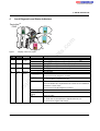
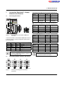
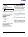
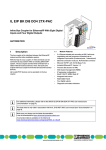
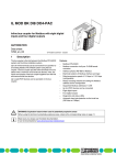
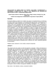
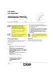
IL DN BK DI8 DO4-PAC
I2
PA
O4I8 D
K D 97211
NB
IL D -No.: 28
er
Ord
C
O1 2 3 4
5 6 7 8 9
N
10
Inline Bus Coupler for DeviceNet™
With 8 Digital Inputs and 4 Digital Outputs
I1
O1
PWR
NT
UL D
M
US N
R
UM
E
2
1
4
3
2
1
4
3
7
5
8
6
Data Sheet
7523_en_00
© PHOENIX CONTACT - 11/2007
Module Features
om
DeviceNet™ connection via TWIN COMBICON
connector
DIP switch to set the DeviceNet™ address
Supported DeviceNet™ addresses 0 to 63
Device description using EDS file
8 digital inputs
4 digital outputs
Diagnostic and status indicators
Automatic baud rate identification in the local bus
(500 kbps or 2 Mbps)
in
ec
–
–
–
–
–
–
–
–
co
DeviceNet™ Features
–
–
–
Faulted node recovery
Baud rates:
125 kBaud, 250 kBaud, 500 kBaud
I/O slave messages:
Polling, Cyclic, Change-of-State (COS), Bit strobing
on
l
–
–
–
–
po
With the help of a bus coupler, 63 Inline terminals can be
connected at any position within an existing DeviceNet™
system. The bus coupler and the Inline terminals together
build a station with 63 local bus devices. Here, the inputs
and outputs of the bus coupler together form the first local
bus device.
ne
The IL DN BK DI8 DO4-PAC bus coupler is the interface
between the DeviceNet™ and the Inline installation system.
Connection of up to 63 I/O modules
Can be installed in the field without software for
automatic configuration of the station
Digital inputs with latch function
Stored (latched) diagnostic data
Reservation of I/O memory area for future expansions
possible (no hardware required)
Supported Inline module types:
Digital inputs and outputs
Analog inputs and outputs
Intelligent function modules
s.
–
–
Description
nt
1
m
AUTOMATION
This data sheet only is valid in connection with the IL SYS INST UM E user manual (see "Ordering Data" on
page 2).
Make sure you always use the latest documentation.
It can be downloaded at www.download.phoenixcontact.com.
A conversion table is available on the Internet at
www.download.phoenixcontact.com/general/7000_en_00.pdf.
This data sheet is valid for all products listed on the following page:
IL DN BK DI8 DO4-PAC
2
Ordering Data
Product
Description
Order No.
Pcs./Pkt
IL DN BK DI8 DO4-PAC
2897211
1
Accessories
Description
Type
Order No.
Pcs./Pkt
DeviceNet™ connector
TMSTBP 2,5/ 5-STF-5,08 GNAU CP
2862576
1
Connector set as replacement item
IL BKDIO-PLSET
2878599
1
Extended double signal connector for inputs,
4 signals with 3-wire connection method
IB IL SCN-12-ICP
2727611
10
Extended double signal connector for outputs,
4 signals with 3-wire connection method
IB IL SCN-12-OCP
m
Type
2727624
10
co
Inline bus coupler for DeviceNet™ with 8 digital inputs and 4 digital outputs
including accessories (end plate, connector and labeling fields)
IL CP
ZB 6 ... see CLIPLINE catalog
2742683
100
1051003
10
ZB 12 ... see CLIPLINE catalog
0812120
10
NS 35/7,5 PERFORATED
NS 35/7,5 UNPERFORATED
0801733
0801681
1
1
End clamp
CLIPFIX 35-5
3022276
50
Type
Order No.
Pcs./Pkt
UM EN IL DN BK DI8 DO4-PAC
2910334
1
AH IL BK IO LIST
9015358
1
IL SYS INST UM E
2698737
1
s.
Zack marker strip to label the terminals
DIN EN 50022 rail, 2 meters
nt
Keying profile
Zack marker strip to label the terminals
User Manual:
"IL DN BK DI8 DO4-PAC Bus Coupler"
Application Note:
"I/O Modules at Bus Couplers"
User Manual:
on
l
in
ec
om
"Automation Terminals of the Inline Product Range"
po
ne
Documentation
Description
7523_en_00
PHOENIX CONTACT
2
IL DN BK DI8 DO4-PAC
3
Technical Data
General Data
Housing dimensions (width x height x depth)
80 mm x 121 mm x 70 mm
Weight
255 g (with connectors)
Ambient temperatures (operation)
-25°C to +60°C
Ambient temperature (storage/transport)
-25°C to +85°C
Permissible humidity (operation/storage/transport)
10% to 95%, according to EN 61131-2
Permissible air pressure (operation/storage/transport)
70 kPa to 106 kPa (up to 3000 m above sea level)
Degree of protection
IP20 according to IEC 60529
Class of protection
Class 3 in acc. with VDE 0106, IEC 60536
m
Connection data for Inline connectors
Spring-cage terminals
Conductor cross-section
0.2 mm2 to 1.5 mm2 (solid or stranded), 24 - 16 AWG
co
Connection type
DeviceNet™ System Data
500 kbps, 250 kbps, 125 kbps
s.
Transmission speed
CR check
Maximum transmission distance
Up to 500 m (depends on transmission speed)
Protocols
Control and information (Common Industrial Protocol) with CAN as transport
medium
nt
Transmission reliability
64, max.
ne
Nodes
Voltage range of the bus coupler (+V, -V)
11 V - 25 V
Nominal current of the bus coupler (+V, -V)
60 mA
ODVA
po
Bus coupler certification
System Limits of Bus Coupler
Number of I/O devices within an Inline system
Maximum number of process data
Maximum number of PCP devices
in
ec
Maximum power supply at UL (7.5 V)
500 kbps or 2 Mbps (automatic detection)
om
Transmission rate on the local bus
63, max.
Limited by Class-Instance maximums
Observe the 2 byte status data of the bus coupler.
8
0.8 A, max.
Maximum power supply at UANA
0.5 A, max.
Maximum power supply at US
8 A, max. (total current with UM)
Maximum power supply at UM
8 A, max. (total current with US)
See terminal-specific data sheet
on
l
Maximum current consumption of the I/O terminals
Observe the current consumption of each device when configuring an Inline station. The current consumption is indicated in each terminalspecific data sheet. The current consumption can differ depending on the individual terminal. If the maximum current capacity of a power
supply is reached, a new power terminal must be used.
DeviceNet™ Interface
CAN bus, connected via TWIN COMBICON connector
Common Data for 24 V Supply UL, US, UM
Connection
Via power connector; for terminal point assignment see page 10
Connection method
Spring-cage terminals
Recommended cable lengths
30 m, max.; routing cables through outdoor areas is not admissible
Continued
Via potential routing
Nominal value
24 V DC
Tolerance
-15%/+20% (according to EN 61131-2)
Ripple
± 5%
Permissible range (according to EN 61131-2)
19.2 V to 30 V
7523_en_00
PHOENIX CONTACT
3
IL DN BK DI8 DO4-PAC
Common Data for 24 V Supply UL, US, UM (Continued)
Safety equipment
Surge voltage, polarity reversal
Yes, suppressor diode parallel to supply voltage
NOTE: The bus coppler is damaged in the event of overload
The 24 V area must be protected externally. The power supply unit must be able to supply 4 times the nominal current of the external fuse, to
ensure that it trips in the event of an error. Recommended fuse 4 A medium blow.
UL (7.5 V) and UANA (24 V) are generated from UL (24 V).
m
Current Consumption / Power Consumption
0.4 A, max.
Current consumption from UANALOG (24 V)
0.5 A, max.
0.9 A, max.
8 A, max.
Current consumption from UM (24 V)
8 A, max.
Power dissipation entire device
3.5 W, max.
Digital Outputs
4
ne
Number
nt
Current consumption from ULOGIC total
Current consumption from US (24 V)
s.
Current consumption local bus (800 mA load at 7.5 V)
co
Current consumption from ULOGIC (24 V)
Connection method for actuators
2 and 3-wire technology
24 V DC
Nominal output voltage UOUT
< 1V
po
Differential voltage for Inom
Nominal current Inom per channel
0.5 A
Total current
2A
Ohmic
Lamp
Inductive
Response time
Overload response
in
ec
Switching frequency with nominal inductive load
om
Nominal load
12 W
12 W
12 VA (1.2 H)
0.5 Hz (1.2 H), maximum
1.2 ms, typical
Auto restart
Response with inductive overload
Output may be damaged
Reverse voltage protection against short pulses
Protected against reverse voltages
on
l
Resistance to permanently applied reverse voltages
Response upon power down
Protected against reverse voltages, permissible current 2A, maximum
The output follows the supply voltage without delay
Limitation of the voltage induced on circuit interruption
-30.0 V, approximately
Safety equipment
Short circuit; overload
Type of safety equipment
Integrated free running circuit in the output chip
Maximum output current when switched off
10 µA
Error message to the higher-level control system
Short circuit; overload
When not loaded, a voltage can be measured even at an output that is not set.
7523_en_00
PHOENIX CONTACT
4
IL DN BK DI8 DO4-PAC
Digital Inputs
Number
8
Connection method for sensors
2 and 3-wire technology
Input design
According to EN 61131-2, type 1
Switching threshold definition
Maximum low-level voltage
ULmax < 5 V
Minimum high-level voltage
UHmin > 15 V
Common potentials
Sensor supply US, ground
Nominal input voltage UIN
24 V DC
Permissible range
-30 V < UIN < +30 V DC
Nominal input current for UIN
3 mA, typical
Limited to a 3 mA, maximum
Delay time
1.2 ms, typical
m
Current flow
100 m
Use of AC sensors
AC sensors in the voltage range < UIN are limited in application
co
Permissible cable length to the sensor
Polarity reversal
Type of safety equipment
Serial diode for polarity reversal protection
Error message to the higher-level control system
Sensor supply not present
s.
Safety equipment
5g load, 2 hours in each space direction
ne
Vibration test sinusoidal vibrations according to IEC 60068-2-6;
EN 60068-2-6
nt
Mechanical Requirements
Shock test according to IEC 60068-2-27; EN 60068-2-27
25 g load for 11 ms, half sinusoidal wave,
3 shocks in each space direction and orientation
po
Conformance With EMC Directive 89/336/EEC or 2004/108/EG
Noise Immunity Test According to EN 61000-6-2
EN 61000-4-2/
IEC 61000-4-2
Electromagnetic fields
EN 61000-4-3
IEC 61000-4-3
Criterion A
Field strength: 10 V/m
Fast transients (burst)
EN 61000-4-4/
IEC 61000-4-4
Criterion A
All interfaces: 1 kV
in
ec
om
Electrostatic discharge (ESD)
on
l
Surge voltage
Conducted interference
Criterion B
6 kV contact discharge
8 kV air discharge
Criterion B
All interfaces: 2 kV
EN 61000-4-5/
IEC 61000-4-5
Criterion B
Supply cables DC:
0.5 kV / 1 kV (symmetrical/asymmetrical)
fieldbus cable shield 1 kV
EN 61000-4-6
IEC 61000-4-6
Criterion A
Test voltage 10 V
Noise Emission Test According to EN 61000-6-4
Noise emission of housing
EN 55011
Class A
Approvals
Information on latest approvals can be found on the Internet at www.download.phoenixcontact.com or www.eshop.phoenixcontact.com.
7523_en_00
PHOENIX CONTACT
5
IL DN BK DI8 DO4-PAC
4
Local Diagnostic and Status Indicators
DeviceNet
PWR
TM
I2
PWR
BF
DIA
UL NT
US MD
UM RN
5 6
7 8
I2
I2
C
4-PA
DO
DI8 1
BK 9721
IL DNr-No.: 28
Orde
I1
O1
O1 2 3 4
5 6 7 8 9
N
10
PWR
NT
UL
MD
US
RN
UM
E
2
1
4
3
2
1
4
3
7
5
8
6
I1
O1
s.
O1
ne
Description of the LED States
24 V bus coupler supply / 7.5 logic voltage is present (ULogic)
24 V bus coupler supply / 7.5 logic voltage is not present
24 V supply of the segment circuit (USegment) is present
24 V supply of the segment circuit is not present
24 V supply of the main circuit (UMain) is present
24 V supply of the main circuit is not present
Network status
Device is online and has established a connection
Group 2 devices are assigned to a master
Error preventing communication with the network
(e.g., bus is offline or duplicate MAC ID).
Device online, connections not established.
in
ec
om
LED
Color
Meaning State
PWR, DeviceNet™
UL
Green
ULogic
ON
OFF
US
Green
USegment ON
OFF
ON
UM
Green
UMain
OFF
NT
Green/
Network
red
status
Green ON
nt
Displays on the bus coupler
po
Figure 1
co
I1
E
1 2
3 4
m
1 2
3 4
Red ON
on
l
Green flashing
Red flashing
Red-green
flashing
OFF
Device has finished the "duplicate MAC ID" test but has not established
connections to other nodes.
Group 2 devices are not assigned to a master.
One or more connections are in the timeout state
Network access error
Device not online
The device has not yet finished the "duplicate MAC ID" test.
The device is not supplied with voltage.
7523_en_00
PHOENIX CONTACT
6
IL DN BK DI8 DO4-PAC
Description of the LED States
Device status (Module Diagnostics)
Normal operation
Unrecoverable error
– Device not configured, or device configuration not complete or
faulty.
– Device in standby mode
Recoverable error
Selftest
RN
Green
Run
"Module Change" alarm during startup
Connection error
Loop diagnostics (e.g., for connected FLM or AS-i modules)
"Module Change" alarm during operation
Configuration error (without other error)
Operation with error data
Peripheral fault (without other errors)
O1
E
Red
1-4
Yellow
I1, I2
E
Red
1-8
Yellow
7523_en_00
in
ec
om
po
Green ON
Green flashing
10 Hz
1 x Green flashing
2 x Green flashing
Green flashing
20 Hz
3 x Green flashing
Green flashing
1 Hz
4 x Green flashing
Green flashing
2 Hz
5 x Green flashing
OFF
No supply voltage
Status of the local Inline communication
Local bus communication present
Initialization phase
m
Red flashing
Red-green
flashing
OFF
co
Green ON
Red ON
Green flashing
s.
Meaning State
nt
Color
Green/
red
ne
LED
MD
Error
ON
on
l
OFF
Output 1
to
ON
Output 4 OFF
Error
ON
OFF
Input 1 to
Input 8
ON
OFF
Error of supply voltage
The bus coupler only operates with integrated inputs and outputs.
No other Inline terminals are snapped on.
Peripheral fault present,
short-circuit or overload at one of the outputs
No short circuit or overload at one of the outputs
Status indicators of the outputs
Output active
Output not active
Peripheral fault present,
short circuit or overload of the sensor supply
No short circuit or overload of the sensor supply
Status indicators of the inputs
Input active
Input not active
PHOENIX CONTACT
7
IL DN BK DI8 DO4-PAC
Circuit Diagram
IB
µP
B
Local bus
5V
A
7,5V
DO1...4
DI1...8
5V
DN
5V
8x DI
24V
24V
24V
4x
DO
US
DN-Interface
U L-
C
US
om
UL
po
UM
UANA
ne
7,5V
nt
24V
U L+
s.
co
3,3V
m
5
US
UM
Key:
DN
µ P
IB
75231002
Circuit diagram of the bus coupler
on
l
Figure 2
in
ec
PWR
Protocol chip
Gray circuit diagram areas represent the electrically isolated areas:
Microprocessor
A: DeviceNet™ interface / Logic
B: Inline Interface
C: I/O devices
Protocol chip
Optocoupler
Supply unit with electrical isolation
PNP transistor
7523_en_00
PHOENIX CONTACT
8
IL DN BK DI8 DO4-PAC
6
6.3
Setting the Address and the Baud
Rate
Configure the hardware on the module using the 10-pos.
DIP switch. This switch can be used to set the DeviceNet™
address and the baud rate. The functions of the individual
switches are listed in the following tables.
IL DN BK DI8 DO4-PAC
Order-No.: 2897211
HW/FW: xx/xxx
PWR
SW9
ON
OFF
ON
OFF
Baud Rate
Can be adjusted using the software.
500 kbaud
250 kbaud
125 kbaud
2
4
1
3
2
4
5 7
6 8
Switch the voltage on and off to accept baud rate
changes.
m
1
3
co
Baud
Auto Cfg
Saved
10
I2
SW8
ON
ON
OFF
OFF
MAC ID
Soft ON ON
500k ON OFF
250k OFF ON
125k OFF OFF
64
32
16
8
4
2
1
I1
The DeviceNet™ transmission speed is set via DIP
switches 8 (SW8) and 9 (SW9). The following table shows
the switch settings for different baud rates.
E
UL NT
US MD
UM RN
OFF ON
1
O1
Baud Rate Settings Using DIP Switches 8 and 9
(Baud)
Configuration of DIP Switch 10
SW
s.
With DIP switch 10, the I/O configuration mode of the bus
coupler is set.
V+
Red
CAN H
White
Drain
Bare
CAN L
Blue
VBlack
nt
ON enables the bus coupler to auto-configure the I/O
modules during the next power-up (Auto Cfg).
ne
With OFF, the bus coupler retains the last valid I/O module
configuration (Saved).
75230006
Address Setting Using DIP Switches 1 to 7
(MAC ID)
om
6.1
Module DIP switches
po
Figure 3
6.2
SW2
32
0
SW3 SW4
16
8
0
0
on
l
ON
OFF
SW1
64
0
in
ec
DIP switches 1 to 7 are used to set the device address (MAC
ID). Here, DIP switch 1 (SW1) is the most significant digit of
the MAC ID (MSB = Most Significant Bit) and DIP switch 7
(SW7) is the least significant digit of the MAC ID (LSB =
Least Significant Bit).
SW5 SW6
4
2
0
0
For further information on the configuration,
please refer to section "Configuration of the Bus
Coupler Using the DIP Switches" on page 11.
Restoring Factory Default Settings
Switch off the voltage supply. Set DIP switches 1 to 7 to the
ON position. Connect the power supply to the bus coupler.
This restores the factory default settings.
SW7
1
0
Valid MAC ID settings are in the range from 0 to
63.
Switch the power off and back on to accept the
address changes.
7523_en_00
PHOENIX CONTACT
9
IL DN BK DI8 DO4-PAC
Terminal Point Assignment of the Power Connector (1)
Connection DeviceNet™, Supply,
Actuators and Sensors
Connecting DeviceNet™
IL DN BK DI8 DO4-PAC
Order-No.: 2897211
HW/FW: xx/xxx
PWR
1
3
2
4
1
3
2
4
5 7
6 8
Terminal
Points
1.1
1.2
1.3
1.4
SW
1.1
1.2
1.3
1.4
1.5
2.1
2.2
2.3
2.4
2.5
po
Connect DeviceNet™ via the TWIN COMBICON connector
to the bus coupler. For the pin assignment, please refer to
the following table:
Description
+24 V DC for UL
CAN High
Shield
CAN Low
GND
om
Signal
V+
CAN H
Drain
CAN L
V-
1.1
UM
UM
GND UM, US
Functional earth
ground (FE)
Terminal
Points
2.1
2.2
2.3
2.4
Assignment
OUT2
PGND
FE
OUT4
in
ec
on
l
Assignment
IN1
US
PGND
IN3
Terminal
Points
2.1
2.2
2.3
2.4
Assignment
IN2
US
PGND
IN4
Terminal Point Assignment of the Input Connector (4)
Terminal
Points
3.1
3.2
3.3
3.4
Install a termination resistor (121 Ω / 0.25 W with
1% tolerance) within the DeviceNet™ system at
each end of the main cable.
7.2
OUT1
PGND
FE
OUT3
nt
Terminal
Points
1.1
1.2
1.3
1.4
ne
Pin assignment of the TWIN COMBICON
connector
Color
Red
White
Blank
Blue
Black
Assignment
Terminal Point Assignment of the Input Connector (3)
75230007
Pin
1.1, 2.1
1.2, 2.2
1.3, 2.3
1.4, 2.4
1.5, 2.5
Assignment
s.
V+
Red
CAN H
White
Drain
Bare
CAN L
Blue
VBlack
Figure 4
Terminal
Points
2.1
US
UL
2.2
GND UL
2.3
Functional earth 2.4
ground (FE)
Terminal Point Assignment of the Output Connector
(2)
Baud
Auto Cfg
Saved
10
I2
MAC ID
Soft ON ON
500k ON OFF
250k OFF ON
125k OFF OFF
64
32
16
8
4
2
1
I1
E
OFF ON
1
O1
UL NT
US MD
UM RN
Assignment
m
7.1
Terminal
Points
1.1
1.2
1.3
1.4
co
7
Assignment
IN5
US
PGND
IN7
Terminal
Points
4.1
4.2
4.3
4.4
Assignment
IN6
US
PGND
IN8
For notes on the voltage supplies please refer to
the IL SYS INST UM E user manual.
Connection of Supply, Actuators and Sensors
PWR
O1
I1
I2
1.1 2.1
1.1 2.1
1.1 2.1
3.1 4.1
1
1
1.2 2.2
1.2
2
1.3
3
1.4
4
2
1.3 2.3
3
1.4 2.4
4
2.1
1.1
1.2 2.2
2.2
1.2
2
2.3
1.3
3
2.4
1.4
4
1
Figure 5
7523_en_00
1
1
1.1
1.2 2.2
2.2
1.2
2
3
2.3
1.3
3
4
2.4
1.4
4
1.4 2.4
1
1
2
1.3 2.3
2
2.1
3.1
1
2.2
3.2
2
3
2.3
3.3
3
4
2.4
3.4
4
1.4 2.4
1
4.1
2
4.2
3
4.3
4
4.4
3.2 4.2
2
1.3 2.3
3
2.1
3.3 4.3
3.4 4.4
4
75240001
Terminal point assignment of the Inline
connectors
PHOENIX CONTACT
10
IL DN BK DI8 DO4-PAC
7.3
Connection Example
8
Connect the bus coupler according to Figure 6.
PWR DO4 DI4 DI4
1
US UM
IN6
+24 V
IN7
For auto-configuration, proceed as follows:
1 Set the device address and the baud rate using DIP
switches 1 to 9.
2 Set DIP switch 10 to "ON".
3 Switch on the bus coupler (DeviceNet™ supply and UL)
with the required I/O modules. If the MD and RN LEDs
on the bus coupler are permanently on (green), the I/O
configuration is saved in the bus coupler’s flash
memory.
4 Set DIP switch 10 to "OFF". This means that autoconfiguration is disabled on the next power up and
ensures that the same active configuration is used on
the next power up.
UM
OUT3
OUT2
75230003
Connection example
For further information on the configuration
options, please refer to the
UM EN IL DN BK DI8 DO4-PAC user manual.
on
l
in
ec
om
po
ne
Figure 6
Procedure for Auto-Configuration
+
DeviceNetTM
+24 V
m
-
co
V+
Red
CAN H
White
Drain
Bare
CAN L
Blue
VBlack
+
-
UL
SW
s.
10
Auto-configuration using the DIP switches enables the bus
coupler to be configured "in the field" without software. This
includes the following standard settings:
– The Inline status word is added by the first two bytes
within the produced response.
– All digital, analog, and function modules are added to
the produced response and/or the consumed request.
4
nt
Baud
Auto Cfg
Saved
3
MAC ID
Soft ON ON
500k ON OFF
250k OFF ON
125k OFF OFF
32
16
8
4
2
1
2
Configuration of the Bus Coupler
Using the DIP Switches
7523_en_00
PHOENIX CONTACT
11
IL DN BK DI8 DO4-PAC
9
Explanations Regarding the I/O
Memory Mapping
For further information on the I/O memory
mapping, please refer to the
UM EN IL DN BK DI8 DO4-PAC user manual.
The Inline status word that is contained in the produced data
per default, can be mapped in the memory image. In
addition to the Inline status word, the input memory image
can contain input data for digital and analog input modules
as well as for function modules.
co
s.
nt
om
po
If the produced data contain diagnostic status
data, such as the Inline status word, this data type
is shown in the input image before the digital data,
analog data or function input data. If the
consumed data contains the command byte, the
command byte appears before the digital, analog,
and function output data in the output data image.
ne
The I/O mapping order is determined by the type and
position of the I/O module. The modules next to the bus
coupler are mapped first. First, the digital points are
mapped, then the analog channels and function modules
are mapped, independent of their physical position within
the Inline station. The analog channels are mapped before
the function data words.
m
The control byte, which is not included by default, is mapped
to the output memory image. In addition to the control byte,
the output memory image can contain output data for digital
and analog output devices as well as function modules.
in
ec
If the overall number of digital points of the same image is
not 8, unused bits are present between the digital and
analog (or function) data area.
on
l
The start of analog data on an even or uneven
byte depends on the I/O modules that are
connected to the bus coupler. When starting on
an odd byte, analog data in the master scanner
could comprise two words. If the analog data is to
start on an even byte, the "Pad I/O" optional I/O fill
function can be enabled. In this way, analog and
function data start on an even byte boundary.
This function can be enabled by an EDS file or by
sending an explicit message. The "Pad I/O"
option is enabled by default.
7523_en_00
PHOENIX CONTACT
12
IL DN BK DI8 DO4-PAC
Example I/O Data Table (Memory Image)
The example consists of the following I/O modules:
– Inline terminal with 2 digital inputs (DI 2)
– Inline terminal with an analog output (AO 1)
– Inline terminal with 2 digital outputs (DO 2)
– Inline terminal with 4 digital inputs (DI 4)
– Inline terminal with 2 analog inputs (AI 2)
– Inline terminal with 4 digital outputs (DO 4)
– Inline counter terminal (CNT)
– Inline supply terminals
For further information on the I/O data table,
please refer to the
UM EN IL DN BK DI8 DO4-PAC user manual.
Figure 7 shows a typical memory image for mixed I/O
module configurations.
O1
I1
I2
1
E
UL NT
US MD
UM RN
Baud
Auto Cfg
Saved
10
1 2
3 4
D
1
4
D
2
1
3
2
4
5 7
6 8
3
4
1
UM
DO8
5
D
3
D
DO8
DO8
D
1
UM
1
D
2
3
DO8
S
3
3
4
4
DO8
8
2
2
3
4
4
DO8
1
6
2
2
3
4
D
G
4
4
DO8
1
OUT
3
1
2
1
2
1
2 1
2
1
2
1
2
1
1
2
1
2
1
Bit 15
E
4
DO8
2
0
Status word, low byte
Byte 0
9
Bit 7
2
Byte 2
SW
8
Status word, high byte
Byte 1
0
Bit 7
0
PE
PE
PE
PE
PE
PE
PE
PE
PE
po
PE
Byte 4
Analog input 1, low byte 1
Bit 15
om
in
ec
on
l
Figure 7
7523_en_00
Bit 7
Bit 15
8
Analog output, high byte
Bit 7
0
Bit 15
8
Bit 7
0
8
Bit 15
8
Counter word 1, high byte
0
8
Counter word 0, high byte
Bit 7
0
Counter word 1, low byte
Bit 15
Byte 11
0
Analog output, low byte
Counter word 0, low byte
Bit 15
Byte 10
Bit 7
Counter word 1, low byte
Analog input 2, high byte 2
Bit 7
0
Not Not Not Not Not Not DO4 DO4
Used Used Used Used Used Used Bit 3 Bit 2
Counter word 0, high byte
0
Bit 15
Byte 7
Byte 9
8
Analog input 2, low byte 2
Byte 6
Byte 8
Bit 7
Counter word 0, low byte
Analog input 1, high byte 1
Byte 5
0
DO4 DO4 DO2 DO2 DO4* DO4* DO4* DO4*
Bit 1 Bit 0 Bit 1 Bit 0 Bit 3 Bit 2 Bit 1 Bit 0
Not Not DI4 DI4 DI4 DI4 DI2 DI2
Used Used Bit 3 Bit 2 Bit 1 Bit 0 Bit 1 Bit 0
ne
Byte 3
0
Bit 7
DI8* DI8* DI8* DI8* DI8* DI8* DI8* DI8*
Bit 7 Bit 6 Bit 5 Bit 4 Bit 3 Bit 2 Bit 1 Bit 0
Bit 7
V+
Red
CAN H
White
Drain
Bare
CAN L
Blue
VBlack
Output Data
m
7
Bit 7
3
MAC ID
Soft ON ON
500k ON OFF
250k OFF ON
125k OFF OFF
64
32
16
8
4
2
1
4
Input Data
CNT
co
PWR
OFF ON
1
DO4
s.
2
DO2 DI4 AI2
nt
Onboard DI2 AO1
DO4* DI8*
I/O Data Tables (As seen by the master)
PWR IN
IL DN BK DI8 DO4-PAC
PWR IN
There are a total number of 11 input bytes (including the
Inline status word) and a total number of 7 output bytes.
Counter word 1, high byte
8
75240011
Typical I/O data table
PHOENIX CONTACT
13
IL DN BK DI8 DO4-PAC
10
Diagnostics
11
Inline Fault Control System
Diagnostic Indicators (LEDs)
Fault Response Mode
For the diagnostic indicators, please refer to section
"Local Diagnostic and Status Indicators" on page 6.
Fault response mode is a configurable setting that will
control the behavior of the outputs of an Inline station, if one
of the following three errors occurs:
– Module change error (bit 3 in Inline status word)
– Configuration error (bit 4 in the Inline status word)
– Module connection error (bit 5 in Inline status word)
For further information on diagnostics, please
refer to the UM EN IL DN BK DI8 DO4-PAC user
manual.
co
The diagnostic information is available via mapped
attributes from the Configuration Object, Class Code 100dec
(64hex).
The bus coupler has the ability to run in the fault response
modes 0 to 3. The mode can be set by sending an explicit
message or by selecting the mode in the fault response
parameter in the EDS file.
m
Diagnostic Objects
In the pre-setting, the Inline diagnostic data (Inline status
word) is available to the user. The diagnostic data starts in
byte 0 of the data field input area and comprises 2 bytes,
see Figure 7.
Fault Response, Mode 0: Stop on Fault (Default)
s.
nt
ne
For standard mapping, the first byte contains the Inline error
code and the second byte contains the number of the first
erroneous I/O module in the Inline station.
Outputs are turned OFF automatically when a local failure
occurs. Once the failure(s) is fixed, either a reconfiguration
(Class 64hex, Instance 1, Attribute 7) or a power cycle (UL
and DeviceNet™ power) needs to occur before the station
becomes operational again.
Fault Response, Mode 1: Auto Restart
Inline Status, Byte 0
po
om
Bit 3
Bit 2
Bit 1
Bit 0
Free
Outputs set in the DeviceNet™ error states
Module connection error
Configuration error (peripheral configuration not
possible)
Module change error
Supply error
I/O error
CRC error
Outputs are turned OFF automatically when a local failure
occurs. Once failure is fixed, the station will begin to update
I/O automatically.
Fault Response, Mode 2: Set to the error state (Go to
Fault State)
Outputs are turned OFF automatically for up to two seconds
when a local failure occurs. After two seconds the station
will attempt to set the outputs to the pre-programed
DeviceNet™ fault states. The station will not recover its lost
I/O, even after the fault condition has been cleared, without
a reconfiguration or power cycle (UL, DeviceNet™). The
default for a preprogrammed fault state is OFF.
on
l
Inline Status, Byte 1
in
ec
Bit 7
Bit 6
Bit 5
Bit 4
The device number in this byte stands for the position in the
Inline station where the error or the warning occurred. The
positions are enumerated and start at
IL DN BK DI8 DO4-PAC with 1. The numbering increments
in physical order from left to right up to 64. This is the
maximum number of devices that can be connected to an
Inline station (63 I/O devices and 1 bus coupler).
7523_en_00
PHOENIX CONTACT
14
IL DN BK DI8 DO4-PAC
12
Supports DeviceNet™ Class Services
Service Code
dec
hex
05
05
14
0E
16
10
po
om
Reset
Get_Attribute_Single
Set_Attribute_Single
co
Class Code
dec
hex
01
01
02
02
03
03
05
05
08
08
09
09
10
0A
11
0B
43
2D
100
64
101
65
102
66
103
67
104
68
105
69
106
70
Object Type
Identity Object
Router Object
DeviceNet Object
Connection Object
Digital Input Point Object
Digital Output Point Object
Analog Input Point Object
Analog Output Point Object
Acknowledge Handler Object
Configuration Object
Inline Interface Object
Inline Module Object
Inline Special Function Object
COS Mask Object
PCP Special Function Object
Serial Communications Object
on
l
in
ec
Service Name
Supports DeviceNet™ Object Classes
ne
The bus coupler supports the standard DeviceNet™
attributes "Fault State" and "Fault Value" for digital and
analog outputs. This means that every output instance can
be configured so that it is set to the pre-programmed state
and value in the event of a DeviceNet™ communication
error. Pre-programming is carried out using an explicit
message and is saved in the flash memory. The states
include:
– Hold last state/value
– Switch off (lower limit value for analog outputs)
– Switch on (upper limit value for analog outputs)
– Specified value (analog outputs)
For more detailed information, please refer to the
UM EN IL DN BK DI8 DO4-PAC user manual.
s.
DeviceNet™ Attributes "Fault State" and "Fault Value"
DeviceNet™ Class Services and
Object Classes
nt
Outputs are turned OFF automatically for up to two seconds
when a local failure occurs. After two seconds the station
will continue to update all I/O that is still on line. The station
will not recover its lost I/O, even after the fault condition is
cleared, without a reconfiguration or power cycle (UL,
DeviceNet™).
m
Fault Response, Mode 3: Continue on Fault
7523_en_00
PHOENIX CONTACT
15
IL DN BK DI8 DO4-PAC
13
the branch line and trunk line. The maximum number of
devices in the DeviceNet™ network is limited to 64.
Information About Networking
DeviceNet™ has a linear bus topology, see Figure 8.
Termination resistors are required at each end of the trunk
line. The branches from the trunk or branch line have a
maximum length of 6 m. Each branch supports one or more
devices. The total length of trunk and branch lines in the
network depends on the line type and/or the baud rate.
Branch Line
A branch line is used to connect devices in the branches to
the trunk line, see Figure 8. They are connected using a
network tap. A branch line is usually thinner and more
flexible than a trunk line and has a lower current carrying
capacity.
The maximum cable length in the network according to the
data rate is listed in the table below. For further details on
cable lengths in the network in relation to the current supply,
please refer to the DeviceNet™ specification.
Termination Resistors
m
To reduce undesired reflections and to ensure stable
communication, termination resistors must be installed at
the extreme ends of the trunk line (including branches), see
Figure 8. For a DeviceNet™ trunk line, the required metal
film termination resistor has a value of 121 Ohm with a
tolerance of 1% and a power dissipation of 0.25 W.
Termination resistors are not supplied as standard with the
bus coupler.
Trunk Line
IL DN BK DI8 DO4-PAC
Order-No.: 2897211
HW/FW: xx/xxx
I1
Drop
cable
I2
E
1
3
2
4
1
3
2
4
5 7
6 8
Soft ON ON
500k ON OFF
250k OFF ON
125k OFF OFF
I1
I2
E
1
3
2
4
1
3
2
4
5 7
6 8
Baud
Auto Cfg
SW
64
32
16
8
4
2
1
O1
s.
I1
I2
E
1
3
2
4
1
3
2
4
5 7
6 8
Baud
Auto Cfg
64
32
16
8
4
2
1
O1
I1
I2
E
1
3
2
4
1
3
2
4
5 7
6 8
Baud
Auto Cfg
Saved
10
PWR
UL NT
US MD
UM RN
OFF ON
1
SW
V+
Red
CAN H
White
Drain
Bare
CAN L
Blue
VBlack
Multiple
node
daisy
chain
IL DN BK DI8 DO4-PAC
Order-No.: 2897211
HW/FW: xx/xxx
64
32
16
8
4
2
1
V+
Red
CAN H
White
Drain
Bare
CAN L
Blue
VBlack
O1
I1
I2
E
1
3
2
4
1
3
2
4
1
3
2
4
5 7
6 8
Baud
Auto Cfg
Saved
10
PWR
UL NT
US MD
UM RN
OFF ON
1
Soft ON ON
500k ON OFF
250k OFF ON
125k OFF OFF
SW
MAC ID
SW
V+
Red
CAN H
White
Drain
Bare
CAN L
Blue
VBlack
Maximum
drop length
6 m (20 ft)
IL DN BK DI8 DO4-PAC
Order-No.: 2897211
HW/FW: xx/xxx
Soft ON ON
500k ON OFF
250k OFF ON
125k OFF OFF
64
32
16
8
4
2
1
PWR
O1
I1
I2
E
UL NT
US MD
UM RN
OFF ON
1
1
3
2
4
5 7
6 8
Baud
Auto Cfg
Saved
10
MAC ID
on
l
1
Saved
10
PWR
UL NT
US MD
UM RN
OFF ON
Soft ON ON
500k ON OFF
250k OFF ON
125k OFF OFF
Figure 8
IL DN BK DI8 DO4-PAC
Order-No.: 2897211
HW/FW: xx/xxx
MAC ID
in
ec
V+
Red
CAN H
White
Drain
Bare
CAN L
Blue
VBlack
om
10
O1
MAC ID
64
32
16
8
4
2
1
PWR
UL NT
US MD
UM RN
OFF ON
1
IL DN BK DI8 DO4-PAC
Order-No.: 2897211
HW/FW: xx/xxx
Soft ON ON
500k ON OFF
250k OFF ON
125k OFF OFF
IL DN BK DI8 DO4-PAC
Order-No.: 2897211
HW/FW: xx/xxx
Saved
Tap
MAC ID
Soft ON ON
500k ON OFF
250k OFF ON
125k OFF OFF
SW
V+
Red
CAN H
White
Drain
Bare
CAN L
Blue
VBlack
Termination
resistor
121 W
Drop
cable
Baud
Auto Cfg
Saved
10
O1
MAC ID
64
32
16
8
4
2
1
PWR
UL NT
US MD
UM RN
OFF ON
1
Tap
po
Zero drop
nt
Trunk cable
Tap
ne
Termination
resistor
121 W
co
The trunk line is used to connect the individual devices and
branches, and thus forms a network, see Figure 8. The trunk
line is used if no branches are required. If branches are
required, taps must be installed at the connection point for
SW
V+
Red
CAN H
White
Drain
Bare
CAN L
Blue
VBlack
Trunk length varies depending on data rate
75240008
Typical DeviceNet™ bus topology
Maximum Cable Length
Baud Rate
DIP Switch Settings for
Baud Rate
125 kbaud
250 kbaud
500 kbaud
8 OFF, 9 OFF
8 OFF, 9 ON
8 ON, 9 OFF
7523_en_00
Length of the Trunk Line
Thick
Thin
500 m
100 m
250 m
100 m
100 m
6m
Length of the Branch
Maximum
Cumulative
6m
156 m
6m
78 m
6m
39 m
PHOENIX CONTACT GmbH & Co. KG • 32823 Blomberg • Germany • Phone: +49-(0) 5235-3-00
PHOENIX CONTACT • P.O.Box 4100 • Harrisburg • PA 17111-0100 • USA • Phone: +717-944-1300
www.phoenixcontact.com
16