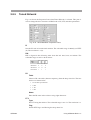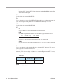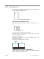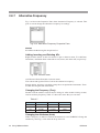
1
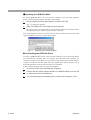
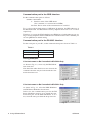
Part No. Z1-002-652, IB003413
Aug. 2005
Userʼs
ʼ Manuall
KSG Series
Application Software (SD001)
Quick Pattern Builder
for KSG3420
Basic Edition
Ver.2.0
Request for Owner’s Registration
You must complete and send in the enclosed owner’s registration card to receive news of software
upgrades and technical support. Please read the Software License Agreement enclosed, complete the
user registration card, and directly fax or mail it to us. If you do not return the user registration card,
you can’t receive the above service.
Use of This User’s Manual
Please read through and understand this User’s Manual before operating the product. After reading, always
keep the manual nearby so that you may refer to it as needed. When moving the product to another location, be sure to bring the manual as well.
If you find any incorrectly arranged or missing pages in this manual, they will be replaced. If the manual it
gets lost or soiled, a new copy can be provided for a fee. In either case, please contact Kikusui distributor/
agent, and provide the “Kikusui Part No.” given on the cover.
This manual has been prepared with the utmost care; however, if you have any questions, or note any errors
or omissions, please contact Kikusui distributor/agent.
Microsoft, and Windows are registered trademarks of Microsoft Corporation, USA.
Windows2000 is a trademark of Microsoft Corporation, USA.
Pentium is a trademark of Intel Corporation, USA.
National Instruments is the registered trademark of National Instruments Corporation, USA.
NI-488, and NI-488.2 are registered trademarks of National Instruments Corporation, USA.
Other company, brand, and product names provided in this manual are trademarks or registered trademarks
of their respective holders.
Reproduction and reprinting of this manual, whole or partially, without our permission is prohibited.
Both product specifications and manual contents are subject to change without notice.
Copyright© 2002-2005 Kikusui Electronics Corporation
Printed in Japan.
Contents
Preface
About This Manual - - - - - - - - - - - - - - - - - - - - - - - - - - - - - - - - - - 3
Overview - - - - - - - - - - - - - - - - - - - - - - - - - - - - - - - - - - - - - - - - - 3
System Requirements - - - - - - - - - - - - - - - - - - - - - - - - - - - - - - - - 4
Chapter 1
Setup
Installation - - - - - - - - - - - - - - - - - - - - - - - - - - - - - - - - - - - - - - - - 5
Uninstallation - - - - - - - - - - - - - - - - - - - - - - - - - - - - - - - - - - - - - - 5
Chapter 2
Using QPB3420 Basic
2.1
Starting QPB3420 Basic - - - - - - - - - - - - - - - - - - - - - - - - - - - - - - - - - 7
2.2
Setting the Communication Port - - - - - - - - - - - - - - - - - - - - - - - - - - - - 7
2.3
Switching between Online/Offline Mode- - - - - - - - - - - - - - - - - - - - - - 10
2.4
Options - - - - - - - - - - - - - - - - - - - - - - - - - - - - - - - - - - - - - - - - - - - - 11
2.5
Preset Memories - - - - - - - - - - - - - - - - - - - - - - - - - - - - - - - - - - - - - - 12
2.6
Managing Data Files - - - - - - - - - - - - - - - - - - - - - - - - - - - - - - - - - - - 13
2.7
Synchronizing Setup Data and the Instruments - - - - - - - - - - - - - - - - 14
2.8
Project Pane and Properties Pane - - - - - - - - - - - - - - - - - - - - - - - - - 14
2.8.1 FM Modulation16
2.8.2 TRI Modulation - - - - - - - - - - - - - - - - - - - - - - - - - - - - - - - - - - 18
2.8.3 RDS Modulation - - - - - - - - - - - - - - - - - - - - - - - - - - - - - - - - - 19
2.8.4 Modified MBS - - - - - - - - - - - - - - - - - - - - - - - - - - - - - - - - - - - 20
2.8.5 Tuned Network - - - - - - - - - - - - - - - - - - - - - - - - - - - - - - - - - - 21
2.8.6 Group Sequence - - - - - - - - - - - - - - - - - - - - - - - - - - - - - - - - - 23
2.8.7 Alternative Frequency - - - - - - - - - - - - - - - - - - - - - - - - - - - - - 24
2.8.8 Radio Text - - - - - - - - - - - - - - - - - - - - - - - - - - - - - - - - - - - - - 25
2.8.9 Program Type Name - - - - - - - - - - - - - - - - - - - - - - - - - - - - - - 26
2.8.10 Other Groups - - - - - - - - - - - - - - - - - - - - - - - - - - - - - - - - - - - 27
Editing Group Types - - - - - - - - - - - - - - - - - - - - - - - - - - - - - - - - 28
Editing TMCs - - - - - - - - - - - - - - - - - - - - - - - - - - - - - - - - - - - - - 29
2.8.11 Other Networks - - - - - - - - - - - - - - - - - - - - - - - - - - - - - - - - - - 36
Editing Other Networks - - - - - - - - - - - - - - - - - - - - - - - - - - - - - - 36
Editing Variant Sequences - - - - - - - - - - - - - - - - - - - - - - - - - - - - 38
Editing AF Method A Items- - - - - - - - - - - - - - - - - - - - - - - - - - - - 39
Editing Mapped Frequency Items - - - - - - - - - - - - - - - - - - - - - - - 40
Index - - - - - - - - - - - - - - - - - - - - - - - - - - - - - - - - - - - - - - - - - - - - - - - - - - - - 43
QPB3420
Contents 1
2 Contents
QPB3420
Preface
About This Manual
This user's manual describes the application software Kikusui Quick Pattern Builder
for KSG3420 Basic Edition.
Applicable Product Version
This user's manual applies to version 2.0x of the application software. In addition,
the firmware version of the KSG3420/3421 to be controlled must be 1.03 or later.
Overview
Kikusui Quick Pattern Builder for KSG3420 Basic Edition (QPB3420 Basic) is a
dedicated program for remotely controlling the KSG3420/3421 via the RS-232C or
GPIB interface. It also provides data management functions including loading and
saving of setup data.
QPB3420 Basic enables you to remotely control the following
items:
FM Stereo Modulator
•
•
•
•
•
FM stereo mode
FM stereo modulation ON/OFF and modulation level
Pilot signal ON/OFF and level
AF source switching and internal AF frequency
Pre-emphasis
RDS/RBDS Data
•
•
•
•
•
•
•
•
•
•
Tuned Network's PI, PTY, PS, etc.
Other Network's PI, PTY, PS, etc.
Group sequence
Variant sequence
Alternative frequency list (Method A only in EON)
Radio text
Mapped frequency list
Program type name
Modified MBS data
TMC data
RDS Modulation
•
•
•
•
•
•
QPB3420
RDS modulation ON/OFF and modulation level
Phase difference with respect to the pilot signal
Composite output level
Error insertion parameter
Clock/Data polarity
Data source
Preface 3
TRI Modulator
•
•
•
•
SK signal ON/OFF and level
DK signal ON/OFF and level
BK signal ON/OFF and level
BK area frequency
Miscellaneous
•
•
•
•
Storing and recalling of preset memory
Setting of memory groups
Memory auto scan ON/OFF
Synchronization of setup data with the instrument
Data Management Function
•
•
•
Opening of preexisting data files
Saving of data files
Creation of new data files
System Requirements
To use QPB3420 Basic, your computer must meet the following requirements:
• A personal computer with a Pentium/100MHz or faster microprocessor, with a
hard disk drive and a CD-ROM drive.
• 32MB or more extended memory.
• 10MB or more free disk space.
• VGA-color or better video subsystem.
• Microsoft Windows 98/Me/NT4/2000/XP and a mouse.
• Microsoft Internet Explorer 4.01 or later.
• A National Instruments or an Agilent Technologies GPIB board installed (if you
use GPIB).
• VISA Library (any one of NI-VISA (Ver.2.6 or later), Agilent VISA (Agilent IO
Libraries K01.00 or later) , and KI-VISA (Ver.2.2.x or later)) installed.
Supported GPIB cards
The following list shows the National Instruments and Agilent Technologies GPIB
adapter cards that are available on the applications. You can select one of these models corresponding to your PC expansion bus.
• AT-GPIB/TNT (National Instruments)
• PCMCIA-GPIB (National Instruments)
• 82350A (Agilent Technologies)
4 Preface
QPB3420
Setup
Chapter 1
Installation
To use QPB3420 Basic, you must first install the QPB3420 Basic and a VISA
library on your personal computer.
This section explains the installation procedure of the QPB3420 Basic and a VISA
library.
■ Installing the VISA Library
A VISA library is required to use the QPB3420 Basic.
The VISA library to be installed varies according to the used I/O interfaces. Not
install different types of VISA library to the same system.
Table1-1
VISA library
I/O interface
VISA library
RS232C
KI-VISA (Ver.2.2.x or later)*1
GPIB by National Instruments
NI-VISA (Ver.2.6 or later)
GPIB by Agilent Technologies
Agilent VISA (Agilent IO Libraries K01.00 or later)
*1. KI-VISA is not required if NI-VISA or Agilent VISA is already installed.
KI-VISA is Kikusui’s original VISA library that supports VXIplug&play VISA
Specification 2.2. The newest version can be downloaded from Kikusui website
(http://www.kikusui.co.jp).
QPB3420
Setup 5
■ Installing the QPB3420 Basic
To install QPB3420 Basic on your personal computer, start the setup program.
Carry out the following steps to start the setup program.
1.
On the taskbar, click the Start button, and then click Run.
Fig. 1-1 dialog box appears.
2.
Enter “D:\Setup.exe” in the Open box and click OK.
The drive letter varies depending on the personal computer environment. Enter
the appropriate drive letter for your personal computer.
The setup program consists of a series of dialog boxes. Follow the instructions that
appear in the dialog boxes to install the program.
Fig.1-1
Specifying the setup program
■ Uninstalling the QPB3420 Basic
To remove QPB3420 Basic from your personal computer, execute Uninstall. When
you uninstall the software, files and register keys that had been installed are
removed from the system. However, only the files and registry keys that the installer
copied or created are deleted. Other files and registry keys that are present even if
the folder had been created by the installer are not deleted.
Carry out the following steps to remove the program.
6 Setup
1.
In Control Panel, open Add/Remove Programs.
2.
Choose Kikusui Quick Pattern Builder for KSG3420 Basic from the list
of software and click Add/Remove.
3.
If a message appears prompting you to restart your computer, do so.
QPB3420
Chapter 2
Using QPB3420 Basic
Except indicated otherwise, the operating procedure of QPB3420 Basic is basically
the same as general Windows programs. For a description of the operating procedure of Windows, see the manual that came with the Windows package.
2.1
Starting QPB3420 Basic
If you have not yet installed QPB3420 Basic on your personal computer, install it
first. For the installation procedure, see page 5, “Installation”.
On the taskbar, click the Start button, and then choose Programs | Kikusui QPB3420
Basic | Quick Pattern Builder for KSG3420 Basic. QPB3420 Basic starts.
2.2
Setting the Communication Port
QPB3420 Basic has two modes: Online mode that immediately applies the setting
changes to the KSG3420/3421 and Offline mode that only changes the data file.
To use Online mode, you must first set the communication port that is to be used to
communicate with the instrument to be remotely controlled.
Set the communication port using the Instruments dialog box. Open this dialog box
by clicking Instruments from the Tools menu.
Enabling or disabling
the communication
Fig.2-1
Setting the communication ports
Instruments dialog box
The settings in the dialog box are saved if you click OK and close the dialog box. If
you click Cancel, the settings return to the previous values.
You must specify either the RDS Modulator (KSG3421) or the RF Signal Generator
(KSG4310) for the FM Stereo Modulator.
NOTE
QPB3420
• If you change the communication port while QPB3420 Basic is running, power
cycle the KSG3420/3421 and then restart QPB3420 Basic.
Using QPB3420 Basic 7
Communication port in the GPIB interface
Set the communication ports as follows.
GPIBn::devname
n: Interface name of the GPIB board
(If n is omitted, it is assumed to be GPIB0.)
devname: Device name of the instrument to be controlled
Fig. 2-1 shows the default setting of QPB3420. In addition, the GPIB addresses of
the KSG3420/3421 and KSG4310 at factory shipment have been set to 11 and 9
respectively.
Therefore, if you use the KSG3420/3421 and KSG4310 of which addresses are setting at factory shipment and the GPIB board of which interface name is GPIB0, you
can use QPB3420 in default setting.
Communication port in the RS-232C interface
For the serial port of your PC, set the communication port as shown in Table 2-1.
Table2-1
PC’s serial port
Communication port
COM1
ASRL1
COM2
ASRL2
Setting examples
If the Instrument to Be Controlled Is KSG3420 Only
As shown in Fig. 2-2, select only the RDS Modulator check box.
Note that if the other check boxes are selected, the
communication bus may be locked until the communication times out.
Fig. 2-2
If the Instrument to Be Controlled Is KSG3421 Only
As shown in Fig. 2-3, select the RDS Modulator
and FM Stereo Modulator check boxes.
In this case, the communication port for the FM
Stereo Modulator must be set to match the communication port for the RDS Modulator. If it is
not, select the same port from the drop-down list.
Fig. 2-3
8 Using QPB3420 Basic
QPB3420
If the Instruments to Be Controlled are KSG3420 and KSG4310
As shown in Fig. 2-4, select the RDS Modulator,
FM Stereo Modulator, and RF Signal Generator
check boxes.
In this case, the communication port for the FM
Stereo Modulator must be set to match the communication port for the RF Signal Modulator. If it
is not, select the same port from the drop-down
list.
Fig. 2-4
If the Instruments to Be Controlled are KSG3421 and KSG4310
As shown in Fig. 2-5, select the RDS Modulator,
FM Stereo Modulator, and RF Signal Generator
check boxes.
In this combination, FM Stereo Modulators are
present on both the KSG3421 and the KSG4310.
Since only one can be used, the communication
port of the instrument you wish to control must
match the communication port for the FM Stereo
Modulator. If it is not, select the same port from
Fig. 2-5
the drop-down list.
If a DC Power Supply Is Present
You can use QPB3420 Basic to turn ON/OFF the output of a Kikusui DC power
supply. Select the DC Power Supply check box if you wish to remotely control the
DC power supply. The output is turned ON/OFF using the Options dialog box. See
the section on the Option dialog box for details.
QPB3420
Using QPB3420 Basic 9
2.3
Switching between Online/Offline Mode
QPB3420 Basic has two modes: Online mode that immediately applies the setting
changes to the KSG3420/3421 and Offline mode that only changes the data file.
To change the mode, click Work Online from the File menu. Online mode is indicated by a check mark to the left of Work Online.
If the status bar is shown, the icon in the left most pane indicates the current mode.
Online
Fig. 2-6
NOTE
Offline
Online mode and Offline mode
• If you wish to switch to Online mode to control the KSG3420/3421 after editing
data in Offline mode, save the file you edited and synchronize the instrument and
the setup data. For details, see section 2.7, “Synchronizing Setup Data and the
Instruments”.
• If communications fail when switching between Offline mode and Online mode,
power cycle the KSG3420/3421 and then restart QPB3420 Basic.
10 Using QPB3420 Basic
QPB3420
2.4
Options
The Options dialog box can be used to remotely control a part of the functions of the
RF signal generator and the DC power supply (power supply controller). Open this
dialog box by clicking Options from the Tools menu.
The communication method with each instrument depends on the setting specified
in the Instruments dialog box. You cannot operate instruments that are not selected
(check box not selected) in the Instruments dialog box.
Fig. 2-7
Options dialog box
RF Signal Generator
The Options dialog box can be used to switch the RF frequency, RF level, and ON/
OFF of the RF output of a Kikusui RF signal generator.
Frequency
Enter the frequency of the RF signal generator in units of MHz. Press MHz to
actually set the generator. For the frequency range setting, see the manual of
the RF signal generator.
Amplitude
Enter the amplitude of the RF signal generator in units of dBµ. Press dBu to
actually set the generator. For the frequency range setting, see the manual of
the RF signal generator.
Output button (RF Signal Generator)
Press Output to turn ON/OFF the RF signal generator. The output is ON when
the button is pressed in.
DC Power Supply (Power supply controller)
The Options dialog box can be used to turn ON/OFF the output of a Kikusui DC
power supply.
Output button (DC power supply)
Press Output to turn ON/OFF the DC power supply. The output is ON when
the button is pressed in.
QPB3420
Using QPB3420 Basic 11
2.5
Preset Memories
The Memory Manage dialog box can be
used to operate the preset memory of the
KSG3420/3421. Open this dialog box by
clicking Memory Manage from the Edit
menu.
Fig. 2-8
Memory Manage dialog
Memory Number
To recall, store, or release a KSG3420/3421 preset memory, you must specify the
preset memory number. Enter the preset memory number in Memory Number and
press Recall, Store, or Release.
Scan Time
Indicates the time until the address indicated in Memory Number is recalled. The
selectable range is 0.0 s to 10.0 s. Specify 0.0 to pass (no recall) and 10.0 to stop
(recall stop).
Recall
Recalls the preset memory specified by Memory Number. The preset memory corresponding to the memory number can be recalled only if the preset memory had been
stored previously.
Store
Stores to the preset memory specified by Memory Number.
Release
Releases the preset memory specified by Memory Number. The preset memory corresponding to the memory number can be released only if the preset memory had
been stored previously.
Memory Status
Displays a report about the recall, store, or release operation.
Group
Select a KSG3420/3421 memory group.
START
Specifies the start address of the selected memory group in terms of the preset
memory number in the range of 0 to END.
END
Specifies the end address of the selected memory group in terms of the preset
memory number in the range of START + 1 to 99.
12 Using QPB3420 Basic
QPB3420
2.6
Managing Data Files
QPB3420 Basic manages the setup data of instruments in a single file in QPML data
format. This allows easy unified management of data free of complicated operations. The QPML file format is Kikusui's original format that expands on XML
(eXtensible Markup Language). The file is a text file.
■ Creating a New Data File
Click New from the File menu. If unsaved data is present, a message prompting you
to save the data appears. Select Yes, No, or Cancel. If you select Yes, a new data file
is created after saving the unsaved data file. If you select No, a new data file is created without saving the unsaved data file. If you select Cancel, the unsaved data file
is not saved, and a new data file is not created.
■ Opening a Preexisting Data File
To open a preexisting data file, click Open from the File menu.
Fig. 2-9
Specifying a file name
A dialog box like the one shown in Fig. 2-9. Specify a file name and click Open.
QPB3420 Basic can load the data that has been created using the KSG3400S Support Software. To load such data, choose KSG3400S Files from the Files of type
drop-down list, and then specify the file name. (QPB3420 Basic cannot save to the
KSG3400S Files format. Save to the QPML format.)
■ Saving the Data File
To save the data file, click Save or Save as from the File menu. Choose Save to overwrite the file. Choose Save as to save the data to a specified file name. If the file
name starts with "Untitled," the Save as dialog box may appear even if you click
Save.
QPB3420
Using QPB3420 Basic 13
2.7
Synchronizing Setup Data and the
Instruments
QPB3420 Basic provides a function for synchronizing the instruments and setup
data only in Online mode. If QPB3420 Basic is in Offline mode, first switch to
Online mode.
Two methods are available for synchronization: Send to that changes the instruments' settings to match the setup data of QPB3420 Basic and Receive from that
changes the setup data of QPB3420 basic to the instruments' settings. Each method
also has Batch all synchronization and partial synchronization.
2.8
Project Pane and Properties Pane
QPB3420 Basic organizes setup items in easy-to-understand groups. Consequently,
all operations are unified and simple.
The groups are shown in a tree structure in the Project Pane on the left. By clicking
an arbitrary group in the tree, the setup items corresponding to the group are displayed in the Properties Pane on the right.
Properties
Pane
Project Pane
Fig. 2-10 Project Pane and Properties Pane
Properties Pane
The Properties Pane that appears varies depending on the tree item selected in the
Project Pane. Properties Pane contains several items that behave differently from
general Windows elements.
Edit Box
On the edit box, you can use the Enter key to confirm an entry. At this point, the settings are immediately applied to the instruments that are controlled if QPB3420
Basic is in Online mode.
List and Grid Controls
Simply carrying out the Add, Insert, or Delete command on list controls and grid
controls do not update the instruments. To apply the changes, click Send from the
14 Using QPB3420 Basic
QPB3420
shortcut menu.
Items that need to be sent
•
Group Sequence
•
Alternative Frequency
•
Other Groups
•
Variant Sequence
•
AF Method A
•
Mapped Frequency
Station 1/Other Groups/Other Networks
Fig. 2-11 shows the Properties Pane when Station 1, Other Groups, or Other Networks is selected. This Properties Pane does not contain any setup items.
Fig. 2-11 Properties Pane for Station 1, Other Groups,
or Other Networks
QPB3420
Using QPB3420 Basic 15
2.8.1
FM Modulation
Fig. 2-12 shows the Properties Pane when FM Modulation is selected. This pane is
used to change the FM Stereo Modulator settings.
Fig. 2-12 Properties Pane for FM Modulation
Stereo Mode
Sets the FM stereo mode. Select one of the following modes:
•
MONO
•
RIGHT
•
MAIN
•
SUB
•
LEFT
•
EXT L/R
FM Stereo
Turns FM stereo modulation ON/OFF and sets the modulation level.
Use the check box to turn ON/OFF FM stereo modulation. Use the edit box on the
right of the label to change the modulation level. The selectable range of modulation
levels is 0.0 % to 125.0 % or 0.0 % to 12.5 %. The modulation level depends on the
Stereo Mode, Audio Frequency (Source), and Pre-Emphasis. Table 2-2 shows the
dependency.
Table 2-2
Stereo Mode
Pre-Emphasis
MONO
MAIN
LEFT
RIGHT
SUB
OFF
EXT L/R
Independence
Audio Frequency
(Source)
Minimum
Maximum
0.0 %
125.0 %
0.0 %
12.5 %
0.0 %
125.0 %
0.0 %
125.0 %
Independence
25 µs
Internal
50 µs
75 µs
External
(Other than OFF)
Independence
In addition, note the dependency shown in Table 2-3.
Table 2-3
Stereo Mode
KSG3421
KSG4310
MONO
100.0 %=75.0 kHz
Other than MONO
100.0 %=67.5 kHz
16 Using QPB3420 Basic
QPB3420
Pilot
Turns FM Pilot signal ON/OFF and sets the level.
Use the check box to turn ON/OFF the pilot signal. Use the edit box on the right of
the label to change the level. The selectable range of levels is 0.0 % to 15.0 %.
Audio Frequency
Sets the AF source and the internal AF frequency.
Use the option buttons to select the AF source. Use the edit box on the right to
change the internal AF frequency. The selectable range of internal AF frequencies
depends on the FM Stereo Modulator as shown in Table 2-4.
Table 2-4
KSG3421
Audio Frequency
(Source)
20 Hz-20.0 kHz
10-Hz resolution
KSG4310
50 Hz-15.0 kHz
50-Hz resolution
Pre-Emphasis
Sets the Pre-Emphasis. Select a value from the drop-down list.
•
OFF
•
25 µs
•
50 µs
•
75 µs
Use caution because the setting affects other parameters. For more details, see the
section FM Stereo.
QPB3420
Using QPB3420 Basic 17
2.8.2
TRI Modulation
Fig. 2-13 shows the Properties Pane when TRI Modulation is selected. This pane is
used to change the TRI modulator settings.
Fig. 2-13 TRI Modulation Properties Pane
SK
Use the check box to turn ON/OFF the SK signal. Use the edit box on the right to
change the level. The selectable range is 0.0 % to 10.0 % in 0.1-% resolution.
DK
Use the check box to turn ON/OFF the DK signal. Use the edit box on the right to
change the level. The selectable range is 0 % to 40 % in 1-% resolution.
BK
Use the check box to turn ON/OFF the BK signal. Use the edit box on the right to
change the level. The selectable range is 0 % to 80 % in 1-% resolution.
Area
Choose the area frequency of the BK signal from the drop-down list. Select a frequency from the choices shown below. A through F indicate the following frequencies.
18 Using QPB3420 Basic
•
A: 23.75 Hz
•
B: 23.75 Hz
•
C: 23.75 Hz
•
D: 39.58 Hz
•
E: 45.67 Hz
•
F: 53.98 Hz
QPB3420
2.8.3
RDS Modulation
Fig. 2-14 shows the Properties Pane when RDS Modulation is selected. This pane is
used to change the RDS modulator settings.
Fig. 2-14 RDS Modulation Properties Pane
RDS
Use the check box to turn ON/OFF the RDS modulation. Use the edit box on the
right to change the modulation level. The selectable range of modulation levels is
0.00 % to 10.00 % in 0.01-% resolution.
Output
Set the output reference level of the composite signal using the edit box. The selectable range is 1.50 Vp-p to 10.00 Vp-p in 0.01-Vp-p resolution.
Phase
Sets the phase difference with respect to the FM pilot signal. Use the drop-down list
to switch between 0˚ and 90˚. Then, use the edit box to vary the phase by ±10˚ (in
units of 1˚) with respect to 0˚ or 90˚.
Error Insertion
Error
Use the check box to turn ON/OFF error insertion. Then, choose the error
insertion logic from the list box. Choose the error insertion logic from the following:
•
OR
•
AND
•
XOR (exclusive OR)
Pattern
Sets the pattern that is inserted based on the error insertion logic in hexadecimal notation. Pattern consists of 26 bits. The lower 10-bits are inserted in
Check word + Offset; Upper 16 bits are inserted in Information word. The
selectable range is 0000000 (h) to FFFF3FF (h). The resolution is 1 (h). However, the actual pattern is the value that results by masking the entered pattern
using FFFF3FF (h).
QPB3420
Using QPB3420 Basic 19
Interval
Sets the interval of blocks to insert the error. The selectable range is 0 to 255.
The resolution is 1. A value of 0 signifies that there are no block intervals.
Thus, errors are inserted in all blocks.
Data Source
Choose the data to be used for RDS modulation from the drop-down list. The
choices are shown below.
•
ALL0
•
PN9
•
ALL1
•
EXT
•
RDS
Clock Polarity
Choose the polarity to be used for RDS clock from the drop-down list. The choices
are shown below.
•
Inverse
•
Normal
Data Polarity
Choose the polarity to be used for RDS data from the drop-down list. The choices
are shown below.
2.8.4
•
Inverse
•
Normal
Modified MBS
Fig. 2-15 shows the Properties Pane when Modified MBS is selected. This pane is
used to change the settings of the Modified MBS that is transmitted as the group
type MBS (OFFSET=E).
Fig. 2-15 Modified MBS Properties Pane
System & Sleep Code
Change the system & sleep code using the edit box. The selectable range is 0000 (h)
to FFFF (h). The resolution is 1 (h).
Receiver ID
Change the receiver ID using the edit box. The selectable range is 0000 (h) to FFFF
(h). The resolution is 1 (h).
Message
Enter the message consisting of 12 characters in the edit box.
20 Using QPB3420 Basic
QPB3420
2.8.5
Tuned Network
Fig. 2-16 shows the Properties Pane when Tuned Network is selected. This pane is
used to change the basic functions of RDS such as PI, PTY, and other parameters.
Fig. 2-16 Tuned Network Properties Pane
PI
Sets the PI code in hexadecimal notation. The selectable range is 0000 (h) to FFFF
(h). The resolution is 1 (h).
PIN
PIN is aligned in the following order from the left: date, hour, and minute. The
selectable range of each is shown below.
Date Hour Minute
Minimum:
0
0
0
Maximum: 31
31
63
Resolution: 1
1
1
PS
Table
Choose a PS code table (character repertory) from the drop-down list. The four
choices are shown below.
•
N: No table specification
•
0: G0
•
1: G1
•
2: G2
Name
Enter the PS name in the edit box using eight characters.
PTY
Type
Set PTY using the edit box. The selectable range is 0 to 31. The resolution is 1.
Flag
Switch PTY flag A and B using the drop-down list.
QPB3420
Using QPB3420 Basic 21
Name
Indicates PTY, Flag, and PTY Name dependent on the RDS/RBDS mode. The
value cannot be changed.
TP
Use the check box to turn ON/OFF TP.
TA
Use the check box to turn ON/OFF TA. Use the edit box to set the burst count of
type-15B groups according to the TA switch. The selectable range is 0 to 9.
M/S
Use the check box to turn ON/OFF M/S.
CT
CT
Use the check box to turn ON/OFF the CT burst function.
MJD
Sets MJD using date/time format. The selectable ranges are shown below.
Year
1900-2100
/ Month / Day
01-12
Hour : Minute
01-31 00-23
00-59
However, the date must be between 1900/03/01 and 2100/02/28.
Offset
Sets the local time offset. The selectable range is -15.5 to 15.5. The resolution
is 0.5.
DI
Use the edit box to set the decoder ID and the dynamic PTY indicator. The selectable range is 0 to 15. The resolution is 1.
The lower 3 bits are assigned to the decoder ID; the highest bit is assigned to the
dynamic PTY indicator. Table 2-5 shows the relationship between the DI value,
decoder ID, and dynamic PTY indicator.
Table 2-5
DI
Decoder ID
Dynamic
PTY indicator
0 to 7
0 to 7
Off
8 to 15
0 to 7
On
Mode
Switches the RDS/RBDS mode.
22 Using QPB3420 Basic
QPB3420
2.8.6
Group Sequence
Fig. 2-17 shows the Properties Pane when Group Sequence is selected. This pane is
used to change the group sequence settings.
Fig. 2-17 Group Sequence Properties Pane
Adding, Inserting, and Deleting Groups
Right-click the mouse on the list control to open a shortcut menu. Use Add Item,
Insert Item, and Delete Item commands to add, insert, and delete groups, respectively.
Fig. 2-18 Shortcut menu
Add Item and Insert Item adds or inserts type-15B groups.
Simply adding, inserting, or deleting groups does not update the instruments. Transmit the data to update the instruments.
Changing Group Types
Double-click the added or inserted item to change it. After double-clicking an item,
enter an arbitrary group type.
Table 2-6 shows the group types that you can enter.
Table 2-6
Type
Value
Version A
0A-15A
Version B
0B-15B
Offset E (=0)
MBS
User-defined
UD1/UD2
Sending/Receiving Sequences (Synchronization)
The Send and Receive commands in the shortcut menu sends or receives the
sequence, respectively, when in Online mode.
QPB3420
Using QPB3420 Basic 23
2.8.7
Alternative Frequency
Fig. 2-19 shows the Properties Pane when Alternative Frequency is selected. This
pane is used to change the alternative frequency list settings.
Fig. 2-19 Alternative Frequency Properties Pane
Method
Switch the method using the drop-down list.
Adding, Inserting, and Deleting AFs
Right-click the mouse on the list control to open a shortcut menu. Use Add Item,
Insert Item, and Delete Item commands to add, insert, and delete AFs, respectively.
Fig. 2-20 Shortcut menu
Add Item and Insert Item adds or inserts 0.000.
The value 0.000 signifies Filler Code for the alternative frequency.
Simply adding, inserting, or deleting groups does not update the instruments. Transmit the data to update the instruments.
Changing the Frequency (Freq)
Double-click the added or inserted item to change it. After double-clicking an item,
enter an arbitrary frequency. Table 2-7 shows the values that you can enter.
Table 2-7
Band
Minimum
Maximum
Resolution
VHF
87.500 MHz
107.975 MHz
0.025 MHz
MF
531 kHz
1602 kHz
9 kHz
LF
153 kHz
279 kHz
9 kHz
Changing the Attributes (Attrb)
When a frequency is added or inserted, the attribute is set to NORMAL. Change the
attribute by choosing a value from the drop-down list.
24 Using QPB3420 Basic
QPB3420
•
NORNAL
•
TUNED
•
ADJREG
Sending and Receiving AFs (Synchronization)
The Send and Receive commands in the shortcut menu sends or receives AF, respectively, when in Online mode.
2.8.8
Radio Text
Fig. 2-21 shows the Properties Pane when Radio Text is selected. This pane is used
to change the radio text settings.
Fig. 2-21 Radio Text Properties Pane
Text A/B Flag
Switch the text flag using the drop-down list.
Changing the Text and Interval
Radio text can be set individually to flag A and flag B. The Text A group box is for
flag A; the Text B group box is for flag B.
Enter the radio text in the large edit boxes. Set the interval in the Interval box.
Receiving Text
Right-click the mouse on the radio text edit box to open a shortcut menu.
Use the Receive command to receive radio text from the instrument.
Fig. 2-22 Shortcut menu
QPB3420
Using QPB3420 Basic 25
2.8.9
Program Type Name
Fig. 2-23 shows the Properties Pane when Program Type Name is selected. This
pane is used to change the program type name.
Fig. 2-23 Program Type Name Properties Pane
Setting the PTY Name
You can set a PTY name individually for RDS and RBDS modes. You can also set a
different PTY name for Flag A and Flag B.
To set the names, double-click on each cell and enter an arbitrary character string.
Press the Enter (Return) key to confirm the entry. (If the PTY name that you entered
is less than eight characters, spaces (20 (h)) are appended at the end.)
26 Using QPB3420 Basic
QPB3420
2.8.10 Other Groups
Other Groups contain a list of group types that KSG3420/3421 handles as other
groups as shown in Fig. 2-24. You can enter encoded data in hexadecimal notation
to each group type.
In addition, you can edit Traffic Message Channel (TMC) data using a dedicated
dialog box.
You can only edit Other Groups in Online mode. Selecting a group type in Other
Groups on the Project Pane causes the current contents of the selected group type to
be sent to the instrument.
The editing procedure is common to all group types. Therefore, an example is given
for group type 1A. The blocks to be edited are as shown in Table 2-8:
Since PI code is sent in the 1st block, only UD1/2 can be entered.
Since PI code is sent in version B of the 3rd block, only UD1/2 can be entered.
Since the KSG3420/3421 automatically calculates and adds the check word and offset word, only UD1/2 can be entered.
Since the KSG3420/3421 calculates and adds the check word for UD1, enter only
the offset for C+O.
Table2-8
2nd
1st
Info
Fig. 2-24 Group types
QPB3420
1A
1B
3A
3B
4A
4B
5A
5B
6A
6B
7A
7B
8A
8B
9A
9B
11A
11B
12A
12B
13A
13B
UD1
UD2
3
3
C+O
3
3
Info
✓
✓
✓
✓
✓
✓
✓
✓
✓
✓
✓
✓
✓
✓
✓
✓
✓
✓
✓
✓
✓
✓
✓
✓
3rd
C+O
Info
✓
4th
C+O
✓
✓
✓
✓
✓
✓
✓
✓
✓
✓
C+O
✓
✓
✓
✓
✓
Info
✓
✓
✓
✓
✓
✓
✓
✓
✓
✓
✓
✓
✓
✓
✓
✓
✓
✓
✓
✓
✓
✓
✓
Using QPB3420 Basic 27
Editing Group Types
Fig. 2-24 shows the Properties Pane when 1A of Other Groups is selected. This pane
is used to change the group type 1A.
Fig. 2-24 Group Type 1A Properties Pane
Adding, Inserting, and Deleting Groups
Right-click the mouse on the grid control to open a shortcut menu as shown in Fig.
2-25 (the Edit TMC command in the menu is appear only for 1A, 3A, 5A, and 8A).
Select Add Item, Insert Item, or Delete Item from the menu.
Fig. 2-25 Shortcut menu
Add Item adds a group to the end.
Insert Item inserts a group before the line containing the active cell.
Delete Item deletes the line containing the active cell.
Editing Groups
Move the cursor to the desired cell and enter a value in hexadecimal notation. Confirm the value after entry by activating another cell using arrow keys or the mouse.
At this point, the high and low limits of the value are checked. If the value is outside
the range, an error message appears. In this case, reenter a value within the range.
Synchronization (Transmission/Reception)
Simply editing group data does not send the data to the KSG3420/3421. Choose
Send or Receive from the shortcut menu.
The Send command sends the edited contents to the KSG3420/3420, while the
Receive command receives the data from the KSG3420/3421 and updates the
QPB3420 Basic data.
28 Using QPB3420 Basic
QPB3420
Editing TMCs
TMC (Traffic Message Channel) data is edited in 1A, 3A, 5A, and 8A of Other
Groups. The setup item varies depending on the group type.
The value of each content is the value in the line containing the active cell on the
grid control.
When you edit the content and click OK or Apply, the edited content is reflected in
the line containing the active cell on the grid control. (The OK button closes the dialog box.)
System Message
System Message is edited using 1A. Choose Edit TMC from the shortcut menu to
open a dialog box as shown in Fig. 2-26.
Fig. 2-26 TMC-System Message dialog
Location Table Number
Enter the value in the edit box. The selectable range is 0 to 63. The resolution is 1.
Service Identifier
Enter the value in the edit box. The selectable range is 0 to 63. The resolution is 1.
System Information
System Information is edited using 3A. Choose Edit TMC from the shortcut menu
to open a dialog box as shown in Fig. 2-27.
Fig. 2-27 TMC-System Information dialog
Variant Code
Choose 0 or 1 from the drop-down list. If 0 is selected, the Variant 0 group box
become editable; if 1 is selected, the Variant 1 group box become editable.
Variant 0
Location Table Number
Enter the value in the edit box. The selectable range is 0 to 63. The resolution
is 1.
QPB3420
Using QPB3420 Basic 29
AF Indicator
Select or clear the check box.
Mode of Transmission
Select or clear the check box.
Message Geographical Scope
Enter the value in the edit box (hexadecimal). The selectable range is 0 to F
(h). The resolution is 1.
Variant 1
Service Identifier
Enter the value in the edit box. The selectable range is 0 to 3. The resolution is
1.
Gap Parameter
Enter the value in the edit box. The selectable range is 0 to 63. The resolution
is 1.
Activity Time
Enter the value in the edit box. The selectable range is 0 to 3. The resolution is
1.
Window Time
Enter the value in the edit box. The selectable range is 0 to 3. The resolution is
1.
Delay Time
Enter the value in the edit box. The selectable range is 0 to 3. The resolution is
1.
ALERT Plus Network Layer Information
ALERT Plus Network Layer Information is edited using 5A or 8A. Here,
explanation is given for setting ALERT Plus Network Layer Information using
8A. First, click the Network Layer Information tab to select the Network Layer
Information page.
Fig. 2-28 TMC-Network Layer Information page
30 Using QPB3420 Basic
QPB3420
Continuity Index
Enter the value in the edit box. The selectable range is 0 to 3. The resolution is 1.
Message
Select a message from the drop-down list. The items to be edited varies depending
on the selected message. Continuity Index is always editable.
Table 2-9 shows the messages and the items to be edited.
Table 2-9
Message
Theme
Cell
Contents to Be Edited
Configuration Number
0-8191
Broadcast Themes
0-255
Theme Number
Informed Cells/Sub-cells
Sub-cell
Theme Number
Informed Cells/Sub-cells
Frequencies
Range
0-7
0-65535
0-7
0-65535
Cell Number
0-15
Theme Number
0-7
Cell Number
0-15
Other Service
Checked or Unchecked
Cell Number
0-15
Frequency
0-255
Tuning Information
Tuning Information is edited using 8A. First, click the Tuning Information tab to
select the Tuning Information page.
Fig. 2-29 TMC-Tuning Information page
Variant Code
Choose a value between 4 and 9 from the drop-down list.
Table 2-10 shows the contents to be edited depending on Variant Code.
QPB3420
Using QPB3420 Basic 31
Table2-10
Variant Code
Contents to Be Edited
4
Service Provider Name
(characters 1 to 4)
5
Service Provider Name
(characters 5 to 8)
Frequencies
(AF of ON)
6
Frequencies
(AF of ON)
PI (AFI=0)
Frequencies
(Tuning Freq.)
7
8
9
Frequencies
(Mapped Freq.)
Range
87.5-108.0
0(h)-FFFF(h)
87.5-108.0
PI (AFI=0)
0(h)-FFFF(h)
PI (AFI=1)
0(h)-FFFF(h)
PI (AFI=1)
0(h)-FFFF(h)
Location Table Number
0-15
Message Geographical
Scope
0-15
Service Identifier
0-63
User Messages
User Messages are edited using 8A. First, click the User Messages tab to select the
User Messages page.
Fig. 2-30 TMC-User Messages page
Variant Code
Choose 0 or 1 from the drop-down list.
If Variant Code is 0, Sixth/Seventh Status cannot be edited. In addition, the high
limit of the contents vary depending on Variant Code. See Table 2-11 for the high
limits.
32 Using QPB3420 Basic
QPB3420
Table 2-11
Variant Code
0
1
Contents to Be Edited
First-Fifth Status
Range
0-15
Collection Number
0-4095
First-Seventh Status
0-7
Collection Number
0-2047
Single Group Full Message
Single Group Full Message is edited using 8A. First, click the Single Group Full
Message tab to select the Single Group Full Message page.
Fig. 2-31 TMC-Single Group Full Message page
Duration/Persistence
Enter an integer in the range of 0 to 7 using decimal notation in the edit box.
Diversion Advice
Select or clear the check box.
Direction
Choose 0 or 1 from the drop-down list.
Extent
Enter an integer in the range of 0 to 7 using decimal notation in the edit box.
Event
Enter an integer in the range of 0 to 2047 using decimal notation in the edit box.
Location
Enter an integer in the range of 0 to 65535 using decimal notation in the edit box.
QPB3420
Using QPB3420 Basic 33
Multi Group Message
Multi Group Message is edited using 8A. First, click the Multi Group Message tab
to select the Multi Group Message page.
Fig. 2-32 TMC-Multi Group Message page
Continuity Index
Enter an integer in the range of 0 to 7 using decimal notation in the edit box.
First Group
Select or clear the check box. If you select the check box, the contents in the First
Group group box become editable. Otherwise, the contents in the Subsequent Group
group box become editable.
Direction
Choose 0 or 1 from the drop-down list.
Extent
Enter an integer in the range of 0 to 7 using decimal notation in the edit box.
Event
Enter an integer in the range of 0 to 2047 using decimal notation in the edit
box.
Location
Enter an integer in the range of 0 to 65535 using decimal notation in the edit
box.
Subsequent Group
2nd Group Indicator
Select or clear the check box.
Group Sequence Identifier
Enter an integer in the range of 0 to 3 using decimal notation in the edit box.
Free Format
Enter an integer in the range of 0 (h) to FFFFFFF (h) using hexadecimal notation in the edit box.
34 Using QPB3420 Basic
QPB3420
ALERT Plus Collection Table Number
ALERT Plus Collection Table Number is edited using 8A. First, click the Collection
Table Number tab to select the Collection Table Number page.
Fig. 2-33 TMC-Collection Table Number page
Service Identifier
Enter an integer in the range of 0 to 63 using decimal notation in the edit box.
Location Table Number
Enter an integer in the range of 0 to 15 using decimal notation in the edit box.
Collection Table Number
Enter an integer in the range of 0 to 63 using decimal notation in the edit box.
QPB3420
Using QPB3420 Basic 35
2.8.11 Other Networks
Editing Other Networks
You can add, insert, or delete EON xx to Other Networks. Each EON xx contains
Variant Sequence, AF with Method A, and Mapped Frequency.
Right-click on Other Networks to open a shortcut menu as shown in Fig. 2-34.
Fig. 2-34 Shortcut menu
If Other Networks is selected, Add Item is valid while Insert Item and Delete Item
are invalid. On the contrary, if EON xx under Other Networks is selected, Add Item
is invalid while Insert Item and Delete Item are valid.
Adding, Inserting, and Deleting Other Networks
Add Item (Alt+A) adds EON xx to the end of EON xx items under Other Networks.
Up to 99 EON xx items can be added or inserted. You can also use the Edit menu to
add, insert, or delete Other Networks.
Insert Item inserts EON xx immediately before the selected EON xx. Up to 99 EON
xx items can be added or inserted.
Delete Item deletes the selected EON xx.
Editing Other Networks
Fig. 2-35 shows the Properties Pane when you select EON xx for editing.
Fig. 2-35 EON #01 Properties Pane
EON #xx
If Group Sequence contains 14A, select whether to send EON data using the check
box.
36 Using QPB3420 Basic
QPB3420
PI
Enter a positive integer in the range of 0 (h) to FFFF (h) using hexadecimal notation.
PIN
The value represents the date, hour, and minute from the left. Enter a positive integer in decimal notation for each value. The selectable range of each is shown below.
Date Hour Minute
Minimum:
0
0
0
Maximum: 31
31
63
Resolution: 1
1
1
You can enter a value exceeding the limit of hour and minute, which are 23 and 59,
respectively. This is because the value depends on the bit length that is allocated by
the RDS/RBDS standard.
PS Name
Enter eight ASCII characters.
Type
Enter a positive integer in the range of 0 (h) to FFFF (h) using hexadecimal
notation.
Burst Count
Enter a positive integer in the range of 0 to 9 using decimal notation.
If PTY of EON is changed, the KSG3420/3421 sends 14A (Variant 13) the
specified number of times in burst mode independent of Group Sequence.
TP
Choose the TP ID of EON using the check box.
TA
Choose the TA ID of EON using the check box.
Burst count
Delay time
For burst count, enter a positive integer in the range of 0 to 9 using decimal notation.
For delay time, enter a decimal number in the range of 0.0 to 9.9. The resolution is
0.1.
Variant 12, 13, 15
See Table 2-12 for the selectable ranges.
Table 2-12
QPB3420
Variant Code
Minimum
Maximum
Resolution
12
0(h)
FFFF(h)
1(h)
13
0(h)
7FE(h)
2(h)
14
0(h)
FFFF(h)
1(h)
Using QPB3420 Basic 37
Editing Variant Sequences
Adding, Inserting, and Deleting Variant Sequences
Select Variant Sequence. The Properties Pane shows a list control. Right-click the
mouse on the list control to open a shortcut menu.
Fig. 2-36 Shortcut menu
Add Item adds an item to the end of the list of items.
Insert Item inserts an item immediately before the selected item.
Delete Item deletes the selected item.
Editing Variant Sequences
Select the item you wish to edit and press the F2 key. An edit box appears above the
item. Enter a positive integer in the range of 0 to 15 in decimal notation. Press the
Enter key to clear the edit box and confirm the new value.
Fig. 2-37 Edit box
Sending and Receiving Variant Sequences
Simply editing Variant Sequence does not update the KSG3420/3421. The Send
command in the shortcut menu sends the edited contents to the KSG3420/3421. The
Receive command receives the contents from the KSG3420/3421 and updates the
QPB3420 Basic data.
38 Using QPB3420 Basic
QPB3420
Editing AF Method A Items
Adding, Inserting, and Deleting AF Method A Items
Select AF Method A. The Properties Pane shows a list control. Right-click the
mouse on the list control to open a shortcut menu.
Fig. 2-38 Shortcut menu
Add Item adds an item to the end of the list of items.
Insert Item inserts an item immediately before the selected item.
Delete Item deletes the selected item.
Editing AF Method A Items
Select the item you wish to edit and press the F2 key. An edit box appears above the
item. Enter the alternative frequency. See Table 2-13 for the selectable ranges. Press
the Enter key to clear the edit box and confirm the new value.
The value 0.000 signifies Filler Code for the alternative frequency.
Fig. 2-39 Edit box
Table 2-13
Bands
Minimum
Maximum
Resolution
VHF
87.500 MHz
107.975 MHz
0.025 MHz
MF
531 kHz
1602 kHz
9 kHz
LF
153 kHz
279 kHz
9 kHz
Sending and Receiving AF Method A Items
Simply editing AF Method A does not update the KSG3420/3421. The Send command in the shortcut menu sends the edited contents to the KSG3420/3421. The
Receive command receives the contents from the KSG3420/3421 and updates the
QPB3420 Basic data.
QPB3420
Using QPB3420 Basic 39
Editing Mapped Frequency Items
Adding, Inserting, and Deleting Mapped Frequency Items
Select Mapped Frequency. The Properties Pane shows a list control. Right-click the
mouse on the list control to open a shortcut menu.
Fig. 2-40 Shortcut menu
Add Item adds an item to the end of the list of items.
Insert Item inserts an item immediately before the selected item.
Delete Item deletes the selected item.
Editing Mapped Frequency Items
Select the item you wish to edit and press the F2 key. An edit box appears above the
item. Enter the alternative frequency. See Table 2-14 for the selectable ranges. Press
the Enter key to clear the edit box and confirm the new value.
Fig. 2-41
Table 2-14
Bands
Minimum
Maximum
Resolution
VHF
87.5 MHz
107.9 MHz
0.1 MHz
MF
531 kHz
1602 kHz
9 kHz
LF
153 kHz
279 kHz
9 kHz
Changing the Attributes (Attrb)
When a frequency is added or inserted, the attribute is set to NORMAL. Change the
attribute by choosing a value from the drop-down list.
40 Using QPB3420 Basic
•
NORNAL
•
TUNED
QPB3420
Sending and Receiving Mapped Frequency Items.
Simply editing Mapped Frequency does not update the KSG3420/3421. The Send
command in the shortcut menu sends the edited contents to the KSG3420/3421. The
Receive command receives the contents from the KSG3420/3421 and updates the
QPB3420 Basic data.
QPB3420
Using QPB3420 Basic 41
42 Using QPB3420 Basic
QPB3420
Index
A
AF Method A Items 39
ALERT Plus Collection Table Number 35
ALERT Plus Network Layer Information 30
Alternative Frequency 24
Area 18
Audio Frequency 17
Group Types 28
I
Installation 5
Instruments dialog box 7
L
list controls 14
B
BK 18
C
Clock Polarity 20
Collection Table Number 35
Communication Port 7
CT 22
D
Data Files 13
Data Polarity 20
Data Source 20
DC Power Supply 11
DI 22
DK 18
M
M/S 22
Mapped Frequency Items 40
Memory Manage dialog box 12
Message 20
Method 24
Mode 22
Modified MBS 20
Multi Group Message 34
N
Network Layer Information 30
O
Edit Box 14
EON #xx 36
Error Insertion 19
Offline mode 10
Online mode 10
Options dialog box 11
Other Groups 27
Other Networks 36
Output 19
F
P
FM Modulation 16
FM Stereo 16
Phase 19
PI 21, 37
Pilot 17
PIN 21, 37
Power supply controller 11
Pre-Emphasis 17
Preset Memories 12
E
G
GPIB cards 4
grid controls 14
Group Sequence 23
QPB3420
Index 43
Product Version 3
Program Type Name 26
Project Pane 14
Properties Pane 14
PS 21
PS Name 37
PTY 21
V
Variant 37
Variant Sequences 38
Version 3
W
Work Online 10
R
Radio Text 25
RDS 19
RDS Modulation 19
Receive from 14
Receiver ID 20
RF Signal Generator 11
S
Send to 14
Sequences 23
Single Group Full Message 33
SK 18
Stereo Mode 16
System & Sleep Code 20
System Information 29
System Message 29
System Requirements 4
T
TA 22, 37
Text A/B Flag 25
TMC 27
TP 22, 37
Traffic Message Channel 27
TRI Modulation 18
Tuned Network 21
Tuning Information 31
U
Uninstallation 5
User Messages 32
44 Index
QPB3420
QPB3420 Application Software User’s Manual