1
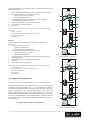
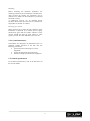
UTF 4000 TX-MSA, UTF 4000 TX, UTF 4000 TX-2, UTF 4000 RX and UTF 4000 RX-2 Optical Video Transmitters/Receivers Multimode USER MANUAL WARNING This is a Class A product. In a domestic environment this product may cause radio interference, in which case the user may be required to take adequate measures. Please read section 6 of this Manual 1. General description 2. Indicators and connectors 5 This user manual is valid for the following models: Model Description Housing UTF 4000 TX-MSA UTF 4000 TX UTF 4000 TX-2 UTF 4000 RX UTF 4000 RX-2 UTF 40xx /SA Transmitter mm Transmitter mm Transmitter mm Receiver mm Receiver mm Stand-alone Rack-mounted Rack-mounted Rack-mounted Rack-mounted Stand-alone Table 1. Models described in this user manual mm = multimode fiber 1 6 2 47,5 4 3 A UTF (Up the FiberTM) transmitter (TX) converts a composite video signal into a high-quality, 9-bit digitised optical equivalent and transmits this over optical fiber. Additionally, the transmitter provides a voltage-free alarm contact (normally open) for door contacts and anti-tamper contacts, for example. Complementary UTF receivers (RX) receive and convert the optical signal to video/contact closure. TX and RX models operate over one multimode optical fiber. TX-2 and RX-2 models are dual units, operating over two multimode optical fibers. All models use one transmission wavelength (1310 nm). A wide range of operating temperatures makes the stand-alone transmitter suitable for use within outdoor camera housings and camera connection boxes (see Technical Specifications). The transmitter can be powered by the camera power supply (12 Vdc or 24 Vac) or by a PSA/PSR 12 DC. For operation under extreme environmental conditions, the PSR 12 DC is recommended. If 24 Vac is used, please read section 3 first. The UTF transmitters (TX, TX-2) and receivers (RX, RX-2) are designed for use in a Siqura MC power supply rack. The UTF 40xx/SA are the stand-alone versions of the rack-mounted models. The TX MSA model is a miniature stand-alone transmitter. Depending on type, the units will handle one (TX, RX) or two (TX-2, RX-2) video/CC channels. The UTF transmitters and receivers are SNM compatible. 7 5 49,7 69,81 Figure 2a. Indications and connectors on the miniature UTF transmitter (stand-alone) 24,5 20,5 Figure 2b. Miniature UTF transmitter (stand-alone), side view Transmitter The miniature stand-alone UTF transmitter has the following parts, indicators, and connectors (figure 2a): 1: 2: 3: 4: 5: 6: 7: TX: optical fiber connection Not used BNC 75 Ω connector composite video input DC: this indicator should show green when the system is powered up using a suitable power supply Mounting bracket 2-Pin connector for potential-free alarm contacts (CC/GND) 2-Pin power supply connector The general connection layout is given in figure 1. video UTF Figure 1. UTF general connection camera contact closure © Siqura 2015 Version 051404-2d UTF MM (MW10) 49,6 fiber UTF monitor cc The rack-mounted UTF transmitter has the following indicators and connections (figure 3): 1. 2. 3. 4. 5. 6. DC: this LED should show green when the system is powered up NV: this LED can show the following colours: Red: no video on in- or output; Off: video signal present. 4-Pin connector for potential-free alarm contacts (channel CC1/GND and channel CC2/GND). BNC 75 Ω connector: composite video output TX: connection for optical fiber Not used Note: Unlike the TX-2 model (shown in figure 3) the rack-mounted TX model comes with one TX connection a 2-pin connector for potential-free alarm contacts one BNC 75 Ω connector one NV LED TM Up-the-Fiber TX-2 VIDEO DC 1 4 NV CHI 2 TX 5 6 3 TX 5 6 Receiver The UTF receiver has the following indicators and connections (figure 4): 1. SYNC: this LED can show: Green: operational link; Red: local synchronisation error; 2. NV: this LED can show the following colours: Red: no video on in- or output Off: video signal present 3. 4-Pin connector for potential-free alarm contacts (channel CC1 and channel CC2) 4. BNC 75 Ω connector: composite video output 5. Not used 6. RX: connection for optical fiber Note: Unlike the RX-2 model (shown in figure 4) the RX model comes with one RX connection a 2-pin output for potential-free alarm contacts one BNC 75 Ω connector one NV LED one SYNC LED VIDEO 4 2 NV CH2 Figure 3. Indications and connections on the UTF TX-2 transmitter TM Up-the-Fiber RX-2 VIDEO SYNC 1 4 NV CHI 2 5 RX 3. Configuration and installation ! Note on powering of a UTF TX-MSA with 24 Vac from the camera ! The miniature stand-alone transmitter can convert 24 Vac power through an internal full rectifier bridge; the "-" of its internal DC voltage is connected to the metal housing. If the camera uses the same Vac power supply in parallel, but with a single-sided rectifier circuit, the UTF power supply diodes may suffer, since there always will be a connection between the housings through the coax cable shielding. To prevent the occurrence of such problems, proper measures must be taken to separate the two loads of the 24 Vac supply; this might be preferable in any case, as a precaution. 6 3 5 RX 6 1 VIDEO SYNC 2 NV 4 CH2 If in doubt, please contact your distributor. Figure 3. Indications and connections on the UTF RX-2 receiver Mounting Before mounting the miniature transmitter, the mounting bracket has to be installed in a suitable place. After securing the bracket, the transmitter can be clicked into it. Make sure the transmitter is positioned and fixed correctly. A stand-alone receiver can be installed almost anywhere. When more than one receiver is needed, use Siqura MC 10 and MC 11 cabinets. Powering up a system When powering up a system, the "DC” indicator on the transmitter (if powered by a suitable power supply) should show green and the "SYNC" indicator on the receiver should also light up green. When no video signal is present, the "NV" indicator(s) show(s) red. 4. Care and maintenance The modules are designed to be maintenance free. To guarantee reliable operation of the unit, take the following precautions: prevent dust from collecting on or in the equipment; protect the equipment against moisture; maintain cooling space around the equipment. 5. Technical specifications For technical specifications, refer to the data sheet of the relevant model. 3 EMC 6. Safety, EMC, ESD This equipment has been tested and found to comply with the limits for a Class A digital device, pursuant to Part 15 of the FCC Rules. These limits are designed to provide reasonable protection against harmful interference when the equipment is operated in a commercial environment. This equipment generates, uses and can radiate radio frequency energy and, if not installed and used in accordance with this instruction manual, may cause harmful interference to radio communications. Operation of this equipment in a residential area is likely to cause harmful interference in which case the user will be required to correct the interference at his own expense. General The safety information contained in this section, and on other pages of this manual, must be observed whenever this unit is operated, serviced, or repaired. Failure to comply with any precaution, warning, or instruction noted in the manual is in violation of the standards of design, manufacture, and intended use of the unit. Installation, adjustment, maintenance and repair of this equipment are to be performed by trained personnel aware of the hazards involved. For correct and safe use of the equipment and in order to keep the equipment in a safe condition, it is essential that both operating and servicing personnel follow standard safety procedures in addition to the safety precautions and warnings specified in this manual, and that this unit be installed in locations accessible to trained service personnel only. Siqura assumes no liability for the customer’s failure to comply with any of these safety requirements. Any interruption of the shielding inside or outside the equipment could cause the equipment to be more prone to fail EMC requirements. Non-video signal lines must use appropriate shielded CAT5 cabling (S-FTP), or at least an equivalent. If system components, such as cabling (e.g. coaxial cable, data/audio/cc wiring) and/or the units, are used outdoors, ensure that all electrically connected components are carefully earthed and protected against surges (high voltage transients caused by switching or lightning). UL/IEC/EN 60950-1: General safety requirements The equipment described in this manual has been designed and tested according to the UL/IEC/EN 60950-1 safety requirements. If there is any doubt regarding the safety of the equipment, do not put it into operation. This might be the case when the equipment shows physical damage or is stressed beyond tolerable limits (e.g. during storage and transportation). Before opening the equipment, disconnect it from all power sources. The equipment must be powered by a SELV*) power supply. When this unit is operated in extremely elevated temperature conditions, it is possible for internal and external metal surfaces to become extremely hot. ESD Electrostatic discharge (ESD) can damage or destroy electronic components. Proper precautions should be taken against ESD when opening the equipment. *) SELV: conforming to IEC 60950-1, <60 Vdc output, output voltage galvanically isolated from mains. All power supplies or power supply cabinets available from Siqura comply with these SELV requirements. 7. Product disposal Recycling Optical safety The unit contains valuable materials which qualify for recycling. In the interest of protecting the natural environment, properly recycling the unit at the end of its service life is imperative. This optical equipment contains Class 1M lasers or LEDs and has been designed and tested to meet IEC 608251:1993+A1+A2 and IEC 60825-2:2004 safety class 1M requirements. Optical equipment presents potential hazards to testing and servicing personnel owing to high levels of optical radiation. When using magnifying optical instruments, avoid looking directly into the output of an operating transmitter or into the end of a fiber connected to an operating transmitter, or there will be a risk of permanent eye damage. Precautions should be taken to prevent exposure to optical radiation when the unit is removed from its enclosure or when the fiber is disconnected from the unit. The optical radiation is invisible to the eye. Use of controls or adjustments or procedures other than those specified herein may result in hazardous radiation exposure. The installer is responsible for ensuring that the label depicted below (background: yellow; border and text: black) is present in the restricted locations where this equipment is installed. Hazard Level 1M The locations of all optical connections are listed in the Indications and Connectors section of this manual. Optical outputs and wavelengths are listed in the Technical Specifications section of this manual. 4