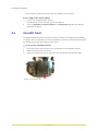
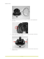
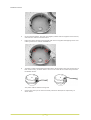
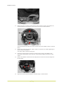
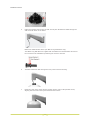
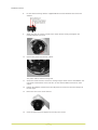
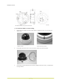
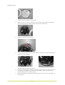
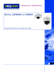
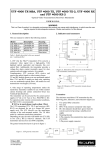
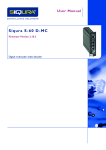
1
FD820M1(IR)
Installation Manual
High-definition fixed dome camera with Day/Night
Note: To ensure proper operation, please read this manual thoroughly before using the
product and retain the information for future reference.
Copyright © 2014 Siqura B.V.
All rights reserved.
FD820
Installation Manual v2 (122002-2)
AIT55
Nothing from this publication may be copied, translated, reproduced, and/or published by
means of printing, photocopying, or by any other means without the prior written permission
of Siqura.
Siqura reserves the right to modify specifications stated in this manual.
Brand names
Any brand names mentioned in this manual are registered trademarks of their respective
owners.
Liability
Siqura accepts no liability for claims from third parties arising from improper use other than
that stated in this manual.
Although considerable care has been taken to ensure a correct and suitably comprehensive
description of all relevant product components, this manual may nonetheless contain errors
and inaccuracies. We invite you to offer your suggestions and comments by email via
[email protected]. Your feedback will help us to further improve our documentation.
How to contact us
If you have any comments or queries concerning any aspect related to the product, do not
hesitate to contact:
Siqura B.V.
Zuidelijk Halfrond 4
2801 DD Gouda
The Netherlands
General : +31 182 592 333
Fax : +31 182 592 123
E-mail : [email protected]
WWW : www.siqura.com
2
Contents
1
2
About this manual .....................................................................................
4
Safety and compliance ..............................................................................
5
2.1
2.2
2.3
3
4
Safety ................................................................................................
Cautions .............................................................................................
Compliance .........................................................................................
5
7
8
Product overview ......................................................................................
9
3.1
3.2
Models ...............................................................................................
Package contents .................................................................................
9
11
3.3
3.4
3.5
Dimensions .........................................................................................
System requirements ...........................................................................
System compatibility ............................................................................
12
12
12
Connectors and cabling .............................................................................
13
4.1
4.2
4.3
4.4
4.5
4.6
5
Connectors .........................................................................................
Power the camera ................................................................................
Connect to network ..............................................................................
Connect audio .....................................................................................
Connect alarm I/O ...............................................................................
microSD Card ......................................................................................
13
14
14
15
15
16
Install the camera .....................................................................................
17
5.1
5.2
5.3
5.4
5.5
Surface Mount .....................................................................................
Long/Mini Wall Mount ...........................................................................
Recessed Ceiling Mount ........................................................................
Corner Mount ......................................................................................
4S Mount Electrical Box ........................................................................
17
22
26
31
35
Index ......................................................................................................
39
3
1
About this manual
What this manual covers
This manual describes how to install and connect the FD820, Siqura's HD fixed dome network
camera. Instructions for configuration and operation of the FD820 can be found in the User
Manual. The Technical Specifications for the FD820 are provided in the FD820 datasheet
(download the latest version at www.siqura.com).
Who should read this manual
This manual is intended for technicians involved in the installation of FD820 cameras.
What you should already know
To be able to install and connect the FD820 properly, you should have adequate knowledge
and skills in the following fields.
●
CCTV systems and components
●
Installing electronic devices
●
Electrical wiring and low-voltage electrical connections
●
Ethernet network technologies and Internet Protocol (IP)
●
Windows environments
●
Web browsers
●
Video, audio, and contact closure transmissions
●
Video compressions methods
Before you start the installation
We advise you to read and observe all instructions and warnings in this manual before you
proceed. Retain this manual with the original bill of sale for future reference and warranty
service. When you unpack your product, check for missing or damaged items. If any item is
missing, or if damage is evident, do not install or operate this product. Contact your supplier
for assistance.
Why specifications may change
At Siqura, we are committed to delivering high-quality products and services. The information
given in this manual was current when published. As we are relentlessly working to improve
our products and user experience, all specifications are subject to change without notice.
We like to hear from you!
Customer satisfaction is our first priority. We welcome and value your opinion about our
products and services. Should you detect errors or inaccuracies in this manual, we would be
grateful if you would inform us. We invite you to offer your suggestions and comments via
[email protected]. Your feedback helps us to further improve our documentation.
4
2
Safety and compliance
This chapter presents the FD820 safety instructions and compliance information.
In This Chapter
2.1 Safety................................................................................................................... 5
2.2 Cautions................................................................................................................7
2.3 Compliance............................................................................................................8
2.1
Safety
The safety information contained in this section, and on other pages of this manual, must be
observed whenever this unit is operated, serviced, or repaired. Failure to comply with any
precaution, warning, or instruction noted in the manual is in violation of the standards of
design, manufacture, and intended use of the module. Siqura assumes no liability for the
customer's failure to comply with any of these safety requirements.
Trained personnel
Installation, adjustment, maintenance, and repair of this equipment are to be performed by
trained personnel aware of the hazards involved. For correct and safe use of the equipment
and in order to keep the equipment in a safe condition, it is essential that both operating and
servicing personnel follow standard safety procedures in addition to the safety precautions
and warnings specified in this manual, and that this unit be installed in locations accessible to
trained service personnel only.
Safety requirements
The equipment described in this manual has been designed and tested according to the
UL/IEC/EN 60950-1 safety requirements. See the CE Declaration of Conformity for
compliance information.
Warning: If there is any doubt regarding the safety of the equipment, do not put it into
operation.
This might be the case when the equipment shows physical damage or is stressed beyond
tolerable limits (for example, during storage and transportation).
Important: Before opening the equipment, disconnect it from all power sources.
The equipment must be powered by a SELV1 power supply. This is equivalent to a Limited
Power source (LPS, see UL/IEC/EN 60950-1 clause 2.5) or a "NEC Class 2" power supply.
When this module is operated in extremely elevated temperature conditions, it is possible for
internal and external metal surfaces to become extremely hot.
1. SELV: conforming to IEC 60950-1, <60 Vdc output, output voltage galvanically isolated
from mains. All power supplies or power supply cabinets available from Siqura comply with
these SELV requirements.
5
Safety and compliance
Power source and temperature ratings
Verify that the power source is appropriate before you plug in and operate the unit. Use the
unit under conditions where the temperature remains within the range given in the Technical
Specifications of this product.
EMC
This device has been tested and found to meet the CE regulations relating to EMC and
complies with Part 15 of the FCC rules. Operation is subject to the following two conditions:
(1) This device may not cause harmful interference, and (2) This device must accept any
interference received, including interference that may cause undesired operation. These limits
are designed to provide reasonable protection against interference to radio communications in
any installation. The equipment generates, uses, and can radiate radio frequency energy;
improper use or special circumstances may cause interference to other equipment or a
performance decrease due to interference radiated by other equipment. In such cases, the
user will have to take appropriate measures to reduce such interactions between this and
other equipment.
Any interruption of the shielding inside or outside the equipment could make the equipment
more prone to fail EMC requirements.
Non-video signal lines must use appropriate shielded Cat 5 cabling (S-FTP), or at least an
equivalent. Ensure that all electrically connected components are carefully earthed and
protected against surges (high voltage transients caused by switching or lightning).
ESD
Electrostatic discharge (ESD) can damage or destroy electronic components. Proper
precautions should be taken against ESD when opening the equipment.
RoHS statement
Global concerns over the health and environmental risks associated with the
use of certain environmentally-sensitive materials in electronic products have
led the European Union (EU) to enact the Directive on the Restriction of the
use of certain Hazardous Substances (RoHS) (2002/95/EC). Siqura offers
products that comply with the EU’s RoHS Directive. The full version of the
Siqura RoHS statement can be viewed at www.siqura.com.
Product disposal
The unit contains valuable materials which qualify for recycling. In the
interest of protecting the natural environment, properly recycling the unit at
the end of its service life is imperative.
When processing the printed circuit board, dismantling the lithium battery
calls for special attention. This kind of battery, a button cell type, contains so
little lithium, that it will never be classified as reactive hazardous waste. It is
safe for normal disposal, as required for batteries by your local authority.
6
Safety and compliance
2.2
Cautions
Handle the camera carefully
Do not abuse the camera. Avoid bumping and shaking. The camera can be damaged by
improper handling or storage.
Do not disassemble the camera
To prevent electric shock, do not remove screws or covers. There are no user serviceable
parts inside. Consult technical support if a camera is suspected of malfunctioning.
Do not use strong or abrasive detergents to clean the camera
Use a dry cloth to clean the camera when it is dirty. If the dirt is hard to remove, use a mild
detergent and wipe gently. To clean the lens, use lens tissue or a cotton tipped applicator and
ethanol. Do not clean the lens with strong detergents.
Never face the camera towards the sun
Do not aim the camera at bright objects. Whether the camera is in use or not, never aim it at
the sun or other extremely bright objects, as this can damage the camera.
7
Safety and compliance
2.3
Compliance
8
3
Product overview
This chapter introduces the FD820 and its features.
In This Chapter
3.1 Models.................................................................................................................. 9
3.2 Package contents.................................................................................................. 11
3.3 Dimensions.......................................................................................................... 12
3.4 System requirements............................................................................................ 12
3.5 System compatibility............................................................................................. 12
3.1
Models
FD820M1 (-SFP)
FD820M1IR (-SFP)
HD Outdoor fixed dome IP camera
●
1/2.7” Progressive scan CMOS imager
●
3.0 - 10.5 mm Motorised varifocal lens
●
Full HD 1080p resolution
●
Quad-stream H.264 and MJPEG video
●
Day/night with IR-cut filter
●
IP66 Ingress protection rating
●
24 Vac / 12 Vdc / 802.3af PoE
●
ONVIF Profile S conformant
●
SFP interface (FD820M1-SFP)
HD Outdoor fixed dome IP camera
●
1/2.7” Progressive scan CMOS imager
●
3.0 - 10.5 mm Motorised varifocal lens
●
Full HD 1080p resolution
●
Quad-stream H.264 and MJPEG video
●
Day/night with IR-cut filter
●
Integrated IR illuminator (effective distance: 25 m)
●
IP66 Ingress protection rating
●
24 Vac / 12 Vdc / 802.3af PoE
●
ONVIF Profile S conformant
●
SFP interface (FD820M1IR-SFP)
9
Product overview
FD820M1IRMP5
HD Outdoor fixed dome camera
●
1/2.5" Progressive scan CMOS imager
●
3.3 to 10.5 mm Motorised lens with push-to-focus
●
5 Megapixel resolution
●
Dual-stream H.264 and MJPEG video
●
Day/night with IR-cut filter
●
Integrated IR illuminator (effective distance: 25 m)
●
IP66 Ingress protection rating
●
24 Vac / 12 Vdc / 802.3af PoE
●
ONVIF Profile S conformant
10
Product overview
3.2
Package contents
FD820
Power terminal block
Conduit
12 Vdc Power adapter
Self-tapping screws (4x)
Plastic screw anchors (4x)
Rubber washers (6x)
White rubber ring
Security torx
Quick Start Guide
CD (software and documentation)
11
Product overview
3.3
Dimensions
3.4
System requirements
The FD820 camera can be accessed and configured from a standard web browser supporting
ActiveX controls. The browsing PC must meet the system requirements described in the table
below.
Item
System requirement
Microprocessor
Intel Pentium M, 2.16 GHz or higher or
Intel CoreTM2 Duo, 2.0 GHz or higher
Memory
At least 2 GB RAM
Operating system
Windows 7
Web browser
Internet Explorer 6.0 or later, Firefox, Chrome, Safari
Network card
10Base-T (10 Mbps) or 100Base-TX (100 Mbps) operation
Viewer
ActiveX control plug-in for Microsoft IE
Minimum requirements
3.5
System compatibility
To ensure system compatibility, you are advised to download the latest firmware at http://
www.siqura.com/.
12
4
Connectors and cabling
This chapter describes the buttons and connectors on the printed circuit board (PCB) of the
FD820 and gives instructions for connecting power, Ethernet, audio, and alarm I/O cables.
In This Chapter
4.1 Connectors...........................................................................................................13
4.2 Power the camera................................................................................................. 14
4.3 Connect to network............................................................................................... 14
4.4 Connect audio...................................................................................................... 15
4.5 Connect alarm I/O................................................................................................ 15
4.6 microSD Card....................................................................................................... 16
4.1
Connectors
The following picture and table describe the reset button and connectors inside the FD820.
13
Connectors and cabling
Connector
Pin No.
Definition
Reset button
-
Press this button for at least 10 seconds to restore the
system to its factory-default settings (including network
settings).
BNC
-
Analogue video output
Alarm I/O
1
Output +
2
Output -
3
Input +
4
Input -
1
Input
2
GND
3
Output (R)
4
Output (L)
1
Power
2
Reserved
3
GND
1
Power-1
2
Earth GND
3
Power-2
-
10/100 Mbps Ethernet / PoE
Audio I/O
Power
DC 12
V
AC 24 V
RJ-45
4.2
Remarks
Alarm connection
Two-way audio transmission
Power connection
Power the camera
Connect the power jack to the FD820 before plugging it into a power socket to avoid danger of
electric shock. Note that the supplied DC power adapter is for indoor use only.
If you use PoE (Power over Ethernet), make sure PoE equipment is in use on the network.
Important: The FD820M1 must use 12 Vdc or 24 Vac for operation below -30°C. The
FD820M1IR and FD820M1IRMP5 must use 12 Vdc or 24 Vac for operation below -10°C.
Using PoE or a power supply, the fan is on whenever the heater is enabled. Power
consumption is 5.5W; 12W with heater/fan (+3.6W for IR option).
4.3
Connect to network
Category 5 Ethernet cable is recommended for network connections. For the best transmission
quality, do not exceed a cable length of 100 metres.
To connect through a hub or switch
●
Connect one end of a straight through Cat 5 cable to the RJ-45 connector of the IP camera
and the other end of the cable to the hub or switch.
14
Connectors and cabling
To connect directly to a PC
●
Connect one end of a crossover Cat 5 cable to the RJ-45 connector of the IP camera and
the other end of the cable to the PC.
Refer to the following figure to determine whether you have established an Ethernet
connection.
Ethernet socket LEDs green/yellow
Green on/off : 100/10 Mbit
Yellow on/blink : link OK, active
Yellow off/flash : link down, TX attempt
4.4
Connect audio
If microphones and speakers are configured to the network, the FD820 can be used to provide
a two-way audio channel.
To connect audio
●
Connect the audio input and output connectors to the terminal block on the back of the
camera.
For the location of this block and the audio connectors, see Connectors.
To configure audio settings
1
Log on to the webpages of the camera.
For instructions on how to do this, see the User Manual.
2
On the Streaming menu, click Audio.
3
Select one of the following options:
- Full-duplex (talk and listen simultaneously)
- Half-duplex (talk or listen, not at the same time)
- Simplex (talk only)
- Simplex (listen only)
- Disable
4.5
Connect alarm I/O
The camera equips one alarm input and one relay output for alarm application.
To connect an alarm device
●
Connect the alarm relay connectors to the terminal block on the back of the camera.
15
Connectors and cabling
For the location of this block and the alarm pin definition, see Connectors.
To configure the alarm settings
1
Log on to the webpages of the camera.
2
Go to the Application, Motion Detection, and Tampering webpages and configure
the alarms as desired.
For instructions on how to do this, see the User Manual.
4.6
microSD Card
The FD820 supports a microSD card (max. 64 GB) for storing event-triggered and scheduled
recordings. Users can format the SD card and implement automatic recording cleanup through
the Storage page on the web interface of the camera.
To access the microSD card slot
1
Remove the dome cover and inner cover as described in the Installation chapter.
2
Release the camera from its housing.
3
Insert the microSD card into the slot at the side of the Printed Circuit Board (PCB).
Location of microSD card slot
16
5
Install the camera
Please read the instructions provided in this chapter thoroughly before installing the FD820.
In This Chapter
5.1 Surface Mount...................................................................................................... 17
5.2 Long/Mini Wall Mount............................................................................................ 22
5.3 Recessed Ceiling Mount......................................................................................... 26
5.4 Corner Mount....................................................................................................... 31
5.5 4S Mount Electrical Box......................................................................................... 35
5.1
Surface Mount
The FD820 can be installed directly on a wall or ceiling. Note that the wall or ceiling must have
enough strength to support the camera.
Items Needed
●
FD820 camera
●
Ethernet cable
●
DC jack cable (supplied; only necessary if not using PoE)
●
Self-tapping screws (supplied)
●
Plastic screw anchors (supplied)
●
Security Torx (supplied)
Required Tools
●
Drill
●
Philips screwdriver
●
Flat-head screwdriver
To install the FD820 on a hard ceiling
1
Release the two captive security screws with the supplied security Torx and open the
dome cover.
FD820 camera
2
Captive Security Screw
Press both sides of the inner cover and remove it from the camera module.
17
Install the camera
3
Unscrew the module-fastened screw, as indicated in the figure, with the phillips-head
screw driver.
4
Press the sides of the snap-on camera module, as indicated in the figure, and detach it
from the dome camera’s housing/plate.
5
Mark the positions of the four screw holes found on the base of the dome camera at the
installation location.
18
Install the camera
6
In the marked locations, drill each hole slightly smaller than the supplied screw anchors,
and insert the anchors into these holes.
7
Fasten the dome camera’s housing/plate with the four supplied self-tapping screws. Use
rubber grommets for outdoor installations.
8
Thread the cables (power/Ethernet/audio/alarm) through either the side conduit entry or
back conduit entry, as shown below. Use a coin to screw off the conduit entry block for
the FD820 camera.
The power cable is omitted if using PoE.
9
Connect the ports (on the camera module) with their cables/wires respectively, as
shown below.
19
Install the camera
10
Attach the snap-on camera module into the dome camera’s housing, and tighten the
module-fastened screw with the screw driver to secure the camera module.
The terminal blocks should face the side conduit entry for the FD820 camera, as shown
above.
11
Connect the power and network outputs. Refer to Connectors for details regarding the
camera connector definition.
The power cable is omitted if using PoE.
12
Access the camera browser-viewer for viewing images. Refer to the FD820's user
manual for further details. Users can also use the camera’s BNC connector for video
output.
13
Position the FD820's motorised lens and adjust the its zoom level and focal length via
the web page.
14
Adjust the camera’s pan/tilt holder to a desired angle, as shown below.
20
Install the camera
Pan adjustment range is nearly 360°; rotation angle range approaches to 270°. Tilt is
adjustable between -10° ~ 90°.
Pan adjustment
Tilt adjustment
Adjust the lens carefully within the limits mentioned above, or the cables underneath
may be harmed.
15
Return the inner cover to the camera module.
16
Replace the back of the dome cover.
Align the arrow mark on the dome cover with the one on the housing as shown in the
figure below.
17
Screw on the two Torx screws on the side of the dome cover tightly to fasten the dome
cover.
21
Install the camera
5.2
Long/Mini Wall Mount
This chapter describes pendant-style mounting of the FD820 cameras with a mini or long wall
mount bracket.
Kit package Contents
WMO7 Long Wall Mount
WM01A Mini Wall Mount
●
M8x16 Hex Head Stainless Steel
Screw (Qty:x1)
●
M8x16 Hex Head Stainless Steel Screw
(Qty:x1)
●
Rubber Washer-8 (Qty:x1)
●
Rubber Washer-8 (Qty:x1)
●
Pendant Tube Washer (Qty:x1)
●
Pendant Tube Washer (Qty:x1)
●
Spring Washer-8 (Qty:x1)
●
Spring Washer-8 (Qty:x1)
●
Plain Washer-8 (Qty:x4)
●
Sponge (Qty:x1)
●
Sponge (Qty:x2)
Required Tools:
●
Drill
●
Phillips screw driver
●
Security Torx (supplied)
Mount dimensions
The installation is the same for both the WM07 Long Wall Mount and the WM01A Mini Wall
Mount shown below.
The WM07 Long Wall Mount dimensions are provided in millimeters in the figures below.
The FD820 standard pendant mount dimensions
22
Install the camera
The WM01A Mini Wall Mount dimensions are provided in millimeters in the figures below.
The FD820 compact pendant mount dimensions
To install the FD820 on a hard wall or ceiling or a square mount electrical
box
1
Unscrew the Security Torx Screws with the supplied Security Torx driver and open the
dome cover.
2
Press both sides of the inner cover and remove it from the camera module.
3
Unscrew the module-fastened Torx Screw, as indicated in the figure.
4
Press the sides of the snap-on camera module, as indicated in the figure, and detach it
from the dome camera’s housing.
23
Install the camera
5
Fasten the pendant mount onto the wall securely Run the Ethernet cable through the
wall mount as shown in the below.
M8x30 Hex Head Machine Screw (for WM07 Long Wall Mount only):
The WM07 Long Wall Mount is supplied with four M8x30 Hex Head Machine Screws for
the convenience of installation by fastening the mount to the wall.
6
Thread the Ethernet cable through the entry of the camera’s housing.
7
Rotate the joint of the dome camera housing into the entry of the pendant mount,
aligning the screw hole of the joint with that of the mount.
24
Install the camera
8
Fix the camera housing with the supplied M8x16 hex head stainless steel screw and
washers.
9
Attach the snap-on camera module to the dome camera housing and tighten the
module-fastened Torx screw.
10
Connect the power and network outputs.
The power cable is omitted if using PoE.
11
Access the camera browser-viewer for viewing images. Please refer to the FD820's user
manual for further details. Users can also use the camera’s BNC connector for video
output.
12
Position the FD820's motorised lens and adjust the its zoom level and focal length via
the web page.
13
Return the inner cover to the camera.
14
Close the dome cover and tighten the security Torx screws.
25
Install the camera
Note: In case the zoom level and focal length are different with the dome cover on, adjust
the zoom level and focal length through the dome cover.
5.3
Recessed Ceiling Mount
The FD820 camera can be installed directly on a wall or ceiling. Please note that the wall or
ceiling must have enough strength to support the camera.
In-ceiling mount package contents
●
T-Bar mount
●
Trim ring
●
Ceiling sticker
●
Required Tools
●
Drill
●
Philips screwdriver
●
Security Torx (provided)
Mount dimensions
The Surface Mount dimensions are provided in millimeters in the figures below.
26
Install the camera
The FD820 recessed ceiling mount dimensions
To install the FD820 on a hard ceiling
1
Release the two captive security screws with the supplied security Torx and open the
dome cover.
FD820 camera
Captive Security Screw
2
Press both sides of the inner cover and remove it from the camera module.
3
Unscrew the module-fastened screw with the phillips-head screw driver, as indicated in
the figure below.
27
Install the camera
4
Press the sides of the snap-on camera module, as indicated in the figure, and detach it
from the dome camera’s housing/plate.
Use a coin to screw off the conduit entry block for the FD820camera.
5
Attach the camera housing/plate’s base to the recessed ceiling mount’s top plate,
aligning the camera’s rear cable entry with the entry hole on the in-ceiling mount’s top
plate.
Align the three captive screws with the mating screw holes on the dome camera’s
housing/plate’s base. Then tighten the three captive screws as shown below.
28
Install the camera
6
Position the supplied adhesive-backed ceiling sticker (Ø176 mm) onto the ceiling where
the camera will be mounted, and cut the ceiling hole using the template as a guide.
7
Insert the dome camera with the attached in-ceiling mount into the opening and run the
Ethernet cable through the desired cable entry.
8
Secure the Unit to the ceiling
Do Not over-tighten the three fixing screws. If using a power tool, the slip clutch should
be set to the lightest setting or the clamps could be damaged.
The in-ceiling mount’s wing clamps will draw the dome camera’s housing/plate to the
ceiling board until it is completely flush with the board.
29
Install the camera
Bottom views of installed in-ceiling mount
9
Attach the snap-on camera module to the dome camera’s housing/plate. Install the
camera module with the terminal blocks facing the side cable entry.
10
Tighten the module-fastening screw.
11
Connect the power and network outputs. Refer to Connectors for details regarding the
camera connector definition.
The power cable is omitted if using PoE.
12
Access the camera browser-viewer for viewing images. Refer to the chapter Accessing
the Camera in the FD820 User Manual for further details. Users can also use the
camera’s BNC connector for video output.
13
Position the FD820's motorized lens and adjust the its zoom level and focal length via
the web page.
30
Install the camera
14
Adjust the camera’s pan/tilt holder to the desired angle. Pan adjustment range is nearly
360°; rotation angle range approaches to 270°.
Tilt is adjustable between -10° ~ 90°.
Adjust the lens carefully within the limits mentioned above, or the cables underneath
may be harmed.
5.4
15
Return the inner cover to the camera.
16
Close the dome cover and tighten the two security screws.
17
Align the three holes in the trim ring with the retaining nut on the in-ceiling mount and
snap the trim ring in place to complete the installation.
Corner Mount
Kit package contents
The Corner Mount Kit package contains:
31
Install the camera
Corner Mount
M4 Plastic Anchors (x 6)
M4 Self-tapping Screws (x 6)
M4 Mechanical Screws (x 4)
Security Torx
Mount dimensions
The Corner Mount dimensions are provided in millimeters in the figures below.
The FD820 corner mount dimensions
Required Tools:
●
Drill
●
Phillips screw driver
●
Security Torx
To install the FD820 on a hard wall or ceiling or a square mount electrical
box
1
Match the corner mount at the ceiling corner. Please note that the dome camera’s
housing/plate installing holes are in position as the right figure.
32
Install the camera
2
Drill six holes on the wall and the ceiling to install six M4 plastic anchors.
Fix the corner mount on the ceiling by fastening six M4 self-tapping screws in the plastic
anchors.
3
Place the dome camera’s housing/plate in the corner mount.
Note: The snap-on camera module is in the position shown in the image above.
4
Thread the RJ-45 cable through the dome camera’s housing/plate.
33
Install the camera
5
Tighten the four M4 mechanical screws to install the dome camera’s housing/plate in the
corner mount.
6
Place the camera module into the dome camera’s housing/plate until there is a “click”
sound.
7
Tighten the screw on the camera module to fix the camera module on the dome
camera’s housing/plate.
8
Connect the power and network outputs. Refer to Connectors for details regarding the
camera connector definition.
The power cable is omitted if using PoE.
9
Access the camera browser-viewer for viewing images. Please refer to the FD820's user
manual for further details. Users can also use the camera’s BNC connector for video
output.
10
Position the FD820's motorized lens and adjust the its zoom level and focal length via
the web page.
11
Install the inner cover on the camera module.
34
Install the camera
12
Place the dome cover back in position, tighten the two Torx screws with the supplied
Security Torx.
Note: In case the zoom level and focal length are different with the dome cover on, adjust
the zoom level and focal length through the dome cover.
5.5
4S Mount Electrical Box
The indoor FD820 cameras can be installed in a 4S Mount Electrical Box.
●
Required Tools
●
Drill
●
Philips screwdriver
●
Security Torx (provided)
To install the FD820 in a 4S Mount Electrical Box
1
Unscrew and open the dome cover with the Security Torx.
2
Run the wires (Ethernet and power) through the wall.
3
Press both sides of the inner cover and remove it from the camera module.
Note: The Power Cable is omitted if using PoE.
35
Install the camera
4
Detach the snap-on camera module from the FD820 camera’s housing/plate by
unscrewing the module-fastened Torx screw first.
Press the sides of camera module and pull it slightly out of the housing/plate.
5
Thread the power and/or Ethernet cables through either the side conduit entry or the
back conduit entry and fasten the camera’s housing/plate to the electrical box with the
two screws.
6
Connect the Ethernet cable to the camera’s network connector. Refer to Connectors for
details regarding the camera connector definition.
7
Connect the power and network outputs. Refer to Connectors for details regarding the
camera connector definition.
8
Access the camera browser-viewer for viewing images. Please refer to the chapter
Accessing the Camera in the FD820 User Manual for further details. Users can also use
the camera’s BNC connector for video output.
9
Position the FD820's motorised lens and adjust the its zoom level and focal length via
the web page.
10
Adjust the camera’s pan/tilt holder to the desired angle.
Pan adjustment range is nearly 360°; rotation angle range approaches 270°.
Tilt is adjustable between -10° ~ 90°.
The power cable is omitted if using PoE.
36
Install the camera
Note: Adjust the lens carefully within the limits mentioned above, or the cables
underneath may be harmed.
11
Attach the snap-on camera module to the dome camera’s housing/plate. Install the
camera module with the terminal blocks facing the side cable entry.
12
Tighten the module-fastening screw.
13
Replace the back of the dome cover.
Align the arrow mark on the dome cover with the one on the housing as shown in the
figure below.
14
Screw on the two Torx screws on the side of the dome cover tightly to fasten the dome
cover.
37
Install the camera
38
Index
4
4S Mount Electrical Box........................... 35
A
About this manual.................................... 4
C
Cautions................................................. 7
Compliance............................................. 8
Connect alarm I/O.................................. 15
Connect audio........................................ 15
Connect to network.................................14
Connectors............................................ 13
Connectors and cabling........................... 13
Corner Mount......................................... 31
D
Dimensions............................................12
I
Install the camera...................................17
L
Long/Mini Wall Mount.............................. 22
M
microSD Card.........................................16
Models.................................................... 9
P
Package contents....................................11
Power the camera...................................14
Product overview......................................9
R
Recessed Ceiling Mount........................... 26
S
Safety.....................................................5
Safety and compliance.............................. 5
Surface Mount........................................17
System compatibility...............................12
System requirements.............................. 12
39