1
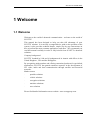
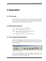
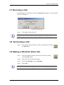
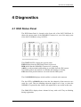
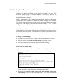
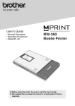
DA-42 MPP Rack Operator Manual Copyright 2008 SCOTTY Group plc. All rights reserved. SCOTTY Group plc. (SCOTTY) retains copyright in this manual and associated user documentation (the Documentation). SCOTTY and its suppliers retain all copyright and other intellectual property rights in the software embedded in and associated with the product described in the documentation (the Software). Some products include unmodified software distributed under GNU General Public License (GPL); please contact SCOTTY for further information and source code. No liability for consequential damages. All rights reserved. By purchasing the product described in the documentation you are granted a limited licence to use the Software, provided you do not copy, alter or adapt the Software in any way including decompiling, disassembling or reverse-engineering. The information provided in the Documentation is believed to be accurate and reliable, however, SCOTTY assumes no responsibility for its use, and reserves the right to revise the documentation without notice. SCOTTY, the SCOTTY logo, MobileTM, ProMaxTM, Z470TM, TeleporterTM, and BeamerTM are Trademarks of SCOTTY Group plc. Microsoft and Windows are registered Trademarks of Microsoft Corporation. Version 2.14.01 SD205864A SCOTTY DA-42 MPP Rack Table of Contents 1 Welcome.............................................................................................5 1.1 Welcome..............................................................................................................5 1.2 Customer Support................................................................................................6 2 System Description ...........................................................................7 2.1 The SCOTTY DA-42 MPP System ....................................................................7 3 Operation............................................................................................9 3.1 First Steps............................................................................................................9 3.2 Starting the System..............................................................................................9 3.3 The Teleport Main Window................................................................................9 3.4 Making a Video Call .........................................................................................10 3.5 Checking or Editing a Phone Book Entry .........................................................10 3.6 Creating a New Phone Book Entry ...................................................................10 3.7 Receiving a Call ................................................................................................11 3.8 Terminating a Call.............................................................................................11 3.9 Making a 256 kbit/s Video Call ........................................................................11 3.10 Recording a Video...........................................................................................12 3.11 Playing Back a Video......................................................................................12 3.12 Transfer of Files with Automatic Hang Up.....................................................13 3.13 Transfer of Files during a Video Call .............................................................13 3.14 Switching Camera ...........................................................................................14 3.15 Making a Still of the Video.............................................................................14 3.16 Turning Off the System...................................................................................14 4 Diagnostics ......................................................................................15 4.1 HSD Status Panel ..............................................................................................15 4.2 EMSHSD SW....................................................................................................16 4.3 Troubleshooting ................................................................................................17 5 Recover ............................................................................................19 5.1 SCOTTY System Recover ................................................................................19 5.1.1 Recovering the Delivery State ..................................................................20 5.1.2 Recovering the Delivery State from CD ...................................................21 Operator Manual 3 SCOTTY DA-42 MPP Rack 5.1.3 Creating Recover-CDs.............................................................................. 22 5.1.4 Creating Your Own Recover Files ........................................................... 23 4 Operator Manual SCOTTY DA-42 MPP Rack 1 Welcome 1.1 Welcome Welcome to the world of advanced communication... welcome to the world of SCOTTY! This manual has been designed to help you take full advantage of your SCOTTY solution. It is not only a comprehensive guide to the operation of the system, it also provides technical details, simple step by step instructions on how to perform the most common applications, and more. We recommend you read this manual carefully in order to fully benefit from SCOTTY's advanced solutions. Company background SCOTTY founded in 1994 and is headquartered in Austria with offices in the United Kingdom , USA and the Philippines. By recognising niche markets and offering customised products for specialised applications, SCOTTY has gained enormous expertise in the development of live video, audio and data communication through satellite and terrestrial networks. Market sectors · portable solutions · vehicle solutions · encryption solutions · maritime solutions · aero solutions Please find detailed information on our website: www.scottygroup.com Operator Manual 5 SCOTTY DA-42 MPP Rack 1.2 Customer Support Contacting SCOTTY's Customer Services & Technical Support: Europe, Middle East, Africa +43 316 409 426 [email protected] The Americas +1 770 825 0574 [email protected] Asia Pacific +63 2 833 7783 [email protected] If you need urgent help for your SCOTTY solution, call the appropriate customer support number for your part of the world: Europe, Middle East, Africa Austria (GMT +1): +43 664 454 2827 The Americas Atlanta, USA (GMT -6): +1 770 380 7186 Asia Pacific Philippines (GMT +8): +63 917 537 0624 Please always include the serial number of your SCOTTY unit or license. Videoconference test numbers H.320 ISDN numbers (64 kbit/s and 2x64 kbit/s): • Austria: +43 316 407849 • USA: +1 770 246 9082 • Asia: +63 2 581 1093 H.323 IP number (up to 512 kbit/s): • Austria: 193.154.221.198 or demograz.scottygroup.com • USA: 209.155.96.99 or demoatlanta.scottygroup.com 6 Operator Manual SCOTTY DA-42 MPP Rack 2 System Description 2.1 The SCOTTY DA-42 MPP System The SCOTTY Group and Diamond Airborne Sensing present a versatile and efficient surveillance solution: the SCOTTY/Diamond DA42 Multi-Purpose Platform (MPP). This twin-turboprop has been outfitted with an observation camera and a beyond line-of-sight satcom link. The video of the observation camera can be recorded locally in full TV quality, and/or sent to a control station in real-time over the satellite link. By combining up to four INMARSAT Swift64 satellite channels, video rates up to 256 kbit/s are possible, using the latest video protocol H.264 to achieve the maximum video quality. The full setup consist of following components: • Diamond DA-42 MPP airplane With its long-range capabilities ideally suited as an airborne platform for surveillance operations. • SCOTTY SATCOM Rack DA-42 MPP The video processing and communication unit integrating these functions: • INMARSAT satellite modem • Windows compatible computer • Live video processing hardware • High-quality video recorder • System control and maintenance software • Antenna subsystem for communication with the INMARSAT satellite network • Controllable camera with optical and FLIR capabilities • Operator console, including video monitors, camera control panel, keyboard and mouse • Inertial Reference System as reference for the antenna positioning Operator Manual 7 SCOTTY DA-42 MPP Rack 3 Operation 3.1 First Steps In the following section we want to make the user familiar with the basic functions of the system. Making a video call, using the quick file transfer feature, recording and playing back videos and additional features of the system are described step by step to be carried out very easily. 3.2 Starting the System Step 1: Start the engines or apply ground power Step 2: Switch on Mission Master and Bus 1 to 6 Step 3: Make sure that the main switch and all fuses of the SCOTTY SATCOM Rack are on Step 4 Windows and Teleporter load itself automatically 3.3 The Teleport Main Window When SCOTTY Teleporter is started, it takes a few moments for the system to initialize. The running initialization steps are displayed in the status bar at the bottom of the Main Window. Video-communication is ready to begin once this process is complete. The Scotty Teleporter Main Window SCOTTY video-communication is as easy as placing a telephone call. The most often used functions are accessible by tool buttons. These and all other functions are also available using the menu bar. Operator Manual 9 SCOTTY DA-42 MPP Rack 3.4 Making a Video Call Step 1: From the standard toolbar of the SCOTTY main window select the Dial button. Step 2: Select the entry of the desired party. Alternatively you can directly enter the phone number into the Number edit field. If you do not want to use the keyboard, clicking at the button Pad opens a dial pad which can be used to enter the number with the input device Step 3: Select Dial. Dial will make a 2 x 64 k bit/s call. To make a 64 kbit/s call, select Low Cost instead. 3.5 Checking or Editing a Phone Book Entry Step 1: From the standard toolbar of the SCOTTY main window select the Dial button. Step 2 Click the Edit Entry button to display information about this specific phone book entry. In order that the ISDN telephone number is valid regardless of the systems present location and the available network type, the telephone numbers should have the following format: +<country code><area code><number>, e.g.+43 316 407849. 3.6 Creating a New Phone Book Entry Step 1: From the standard toolbar of the SCOTTY main window select the Dial button. Step 3: Click New Entry. Step 4: Enter name and number and press OK. 10 Operator Manual SCOTTY DA-42 MPP Rack 3.7 Receiving a Call An incoming call is announced by the Incoming Call dialog box of the opened SCOTTY Teleporter. The Incoming Call dialog box Step 1: Click Yes to accept the call. If no action is taken, the system reacts according to the pick-up settings. On default, automatic pickup is activated and the call is put through after a moment's pause. 3.8 Terminating a Call Step 1: The ongoing videoconference can be terminated by clicking the Dial button. 3.9 Making a 256 kbit/s Video Call Step 1: From the standard toolbar of the SCOTTY main window select the Dial button. Step 2: Select the entry of the desired party. Step 3: In the field Dial Rate, choose 4 Bonding. Step 3: Select Dial. The unique SCOTTY Live Bonding feature is necessary for bonding calls over satellite links. For calls with systems that do not support this protocol, see chapter Making a Video Call. Operator Manual 11 SCOTTY DA-42 MPP Rack 3.10 Recording a Video Step 1: From the standard toolbar of the SCOTTY main window select the Recorder button. Step 2: Start the recording. Step 3: Stop recording. The recording is saved under D:\Scotty\Records with an automatically assigned name. Step 4: The name of the saved recording is now displayed in the field File of the section "Play" and can be played back with the Play button if desired. Video can also be recorded during a video call. Because the SATCOM Rack is optimized for surveillance operations, it will record the local camera video, not the video call. 3.11 Playing Back a Video Step 1: From the standard toolbar of the SCOTTY main window select the Recorder button. According to the setting under Options | Recorder the MPEG Recorder is opened. Step 2: In the section "Play" choose the Browse button, select one of the recorded files on the hard drive and choose Open. To play back a previously received file, browse to the D:\Scotty\Incoming directory. Step 3: Press the Play button. 12 Operator Manual SCOTTY DA-42 MPP Rack 3.12 Transfer of Files with Automatic Hang Up Step 1: From the standard toolbar of the SCOTTY main window select the File Transfer button. Step 2: Click on Add. Step 3: In the "Open" dialog select the file to transmit and press Open. Step 4: Repeat Step 2 and Step 3 to add several files to the displayed list. Step 5: Click on Send. Step 6: Select the entry of the desired party and click Dial. The SCOTTY File Transfer is only possible between two SCOTTY systems using Teleporter or the File Transfer software. 3.13 Transfer of Files during a Video Call Step 1: Establish a videoconference (see chapter Making a Video Call). Step 2: After connection has been established, select the File Transfer button. Step 3: Click on Add. Step 4: In the "Open" dialog select the file to transmit and press Open. Step 5: Repeat Step 3 and Step 4 to add several files to the list. Step 6: Click on Send. The SCOTTY File Transfer is only possible between two SCOTTY systems using Teleporter or the File Transfer software. Operator Manual 13 SCOTTY DA-42 MPP Rack 3.14 Switching Cameras Step 1: Select a camera preset. Preset A switches to the FLIR camera. Preset B activates Video In 2. Preset C is available for user-defined video and audio settings. 3.15 Making a Still of the Video Step 1: Click on the Snapshot button. The still is now copied into the clipboard. Step 2: Open a Windows drawing software (e.g.: MS-Paint) and paste the copied still. Step 3: Save the document. 3.16 Turning Off the System Step 1: Close the SCOTTY Teleporter main window with and confirm the appropriate message. Step 2: Click on Start (usually lower left corner). Step 3: Click on Turn Off Computer. Step 4: Select the option Turn Off. Step 5: Wait until Windows has finished shut down. Step 6: Turn off Bus 1 to 6, and then turn off Mission Master. If the system is not shut down in the correct fashion, data-loss can occur. Congratulations! You have now mastered the main functions of the SCOTTY SATCOM System successfully. For more information, please refer to the “SCOTTY ProMax User’s Manual”, part number SD204500A. 14 Operator Manual SCOTTY DA-42 MPP Rack 4 Diagnostics 4.1 HSD Status Panel The HSD Status Panel is located on the front side of the SATCOM Rack. It shows the current status of the INMARSAT transceiver, one of the major parts of the SATCOM Rack, using 16 LED’s. The SCOTTY HSD Status Panel The STATUS LED’s display the general status: PWR displays that the HSD Status Panel is powered. HSD shows that the INMARSAT transceiver is running. A&H is on when attitude and heading are available from the IRS system. It is blinking when only attitude is available and heading is missing. GPS shows that position data are received from the IRS system. The field REGION displays which satellite is selected at the moment. The four LED’s in READY show when the four channels of the transceiver are ready for a call. They are blinking when the signal level is low, or when the INMARSAT registration has failed; calls might still be successful in this state. The CON LED’s display when a channel is busy with a call. They are blinking during registration. Operator Manual 15 SCOTTY DA-42 MPP Rack 4.2 EMSHSD SW The EMSHSD software provides easy access to the INMARSAT transceiver, and diagnostics of the overall system. The software can be started directly from the Windows Desktop by doubleclicking the EMSHSD01 icon. The SCOTTY EMSHSD Software The field System shows the time and date of the transceiver. Flight Information displays the current IRS information, as received by the transceiver from the SCOTTY IRS system. Please note that the Heading displayed is the true heading, not the magnetic heading. Satellite shows the INMARSAT satellite that is selected at the moment, together with the azimuth and elevation data for the antenna pointing. The status of the four channels is shown in the section Channels: The column Status displays the current status of each channel, like “orr” (registration in progress), “no call” (channel is idle), “data” (data call), or “no dial” (channel is not available). The current signal level is displayed in the column C/No. The signal level should be greater that 48 dB/Hz for stable calls. The temperature of the channel card hardware is shown under Temp. 16 Operator Manual SCOTTY DA-42 MPP Rack During a call, Frequency displays the uplink frequency. The line after each channel’s information columns shows detailed call status information for the channel, like call type details, call direction (mobile or fixed), error text when a connection is terminated, and status information during the registration process. Start Capture captures the raw data status data received from the SATCOM transceiver, e.g. for diagnostic purposes. The Open Terminal button opens a second window which enables direct access to the SATCOM transceiver’s maintenance port. Setup and advanced diagnostics are possible by using the terminal window. 4.3 Troubleshooting No Power · Check Mission Master · Check Bus 1 to 6 · Check Main ON/OFF Switch of the SatCom Rack · Check Fuses of the SatCom Rack No Calls Possible · Check Line of Sight · Check EMSHSD Status Display (Status and Region) · Check EMSHSD Software (Flight Information and Satellite) Calls Start, but No Connection · Check Phone number and its format (+country code…) · Check EMSHSD Status Display (CH1 - CH4) · Check EMSHSD Software (C/N value) · Try other call direction (e.g. incoming calls instead of outgoing calls) · Try lower calling rates (Low-Cost calls) No Video Operator Manual · Check Camera Power (Bus 3) · Check Camera ON/OF (hand controller) 17 SCOTTY DA-42 MPP Rack · Check Teleporter Settings (A, B, C) · Check video splitter No Audio · Check Teleporter Settings · Check IC · Check IC Settings · Check Headset HSD Fault (Red LED) · Check transceiver with EMSHSD Software (Open Terminal) No Windows or Teleport Start-up · 18 Recover the PC system (see chapter Recover) Operator Manual SCOTTY DA-42 MPP Rack 5 Recover 5.1 SCOTTY System Recover SCOTTY systems feature a unique integrated system recovery which makes it possible to bring the system back to its delivery state. If, for example, system files have been damaged or destroyed by accident, the operating system or applications may not work correctly anymore. By restoring the delivery state, the system will be fully operational again. SCOTTY systems use three partitions on the hard disk. System partition C: contains the operating system and the installed application, the data partition D: is used for storing data, the phone book etc. An additional hidden partition is used for the SCOTTY System Recover. Restoring the delivery state is possible directly on the system without any additional components. By using an additional partition this is even possible if the system is severely damaged and Windows can not even start. In case that system recover is not available any more due to changing the hard disk or because the recover partition has been destroyed, the system can be brought back to delivery state by the recover-CD. In conclusion, the SCOTTY System Recover has the following features: • Restoring the delivery state of the system configuration without any recoverCD, the data partition will be conserved. • Restoring the delivery state of the system configuration and the data partition without any recover-CD. • Restoring the delivery state of the complete hard disk using the bootable recover-CD. • Creating a new recover-CD on the system. • Protecting the individual functions against unauthorized access by assigning individual passwords. • Optional: Creating your own recover snapshots. With this feature it is not only possible to restore the delivery state, but additionally save and restore any other system state. Contact your local SCOTTY representative on how to obtain a license for this feature. Operator Manual 19 SCOTTY DA-42 MPP Rack 5.1.1 Recovering the Delivery State Open the Recover Menu: • Reboot your system • While booting, the following menu is visible for a few seconds: • Select Recover by pressing the Page down key and Return. • Enter "restore" when asked for the password. • The system recover menu is displayed: By selecting the menu entry Info (7) information about the hardware and software configuration is displayed. Recovering the Delivery State of the System Partition: • Select the menu entry Recover system partition with Factory Image by pressing the key 2. • Confirm the security inquiry with Yes by pressing the key 8. Warning: If the system partition is restored to delivery state, all data which has been stored on drive C: after delivery is permanently lost. The data partition D: is not affected by this, e.g. the phone book will be conserved . Recovering the Delivery State of the Whole System: • Select the menu entry Recover system and data partition with Factory Images by pressing the key 1. • Confirm the security inquiry with Yes by pressing the key 8. Warning: If the system is restored to delivery state, all data which has been stored on drives C: or D: after delivery is lost. 20 Operator Manual SCOTTY DA-42 MPP Rack 5.1.2 Recovering the Delivery State from CD Recovering the system using the recover-CD is usually only necessary if a new, empty hard disk is inserted or if the recover partition has been destroyed. • Insert the first recover-CD with the serial number of the system. • Reboot your system. Booting from CD is enabled by default. If this has been disabled, carry out the following steps (this can slightly differ depending on the actual BIOS-Version): Open the BIOS Setup by pressing Del at the begin of the boot sequence. Select BIOS FEATURES SETUP, change Boot Sequence to CDROM, C, A and save this change. • The system will now boot from the CD-ROM drive. • The CD recover menu is displayed: • Select the menu entry Recover whole hard disc by pressing the key 2. • Confirm the security inquiry with Yes by pressing the key 8. Warning: If the whole hard disk is restored to delivery state, all data, which has been stored to drives C: or D: after delivery, or any additional recovery files are permanently lost. When recovering from CD only the complete hard disk can be restored. Recovering only the system partition can be performed without the recover-CD, see chapter "Recovering the Delivery State". The menu entry Recover system partition only... displays appropriate help information for the user. Operator Manual 21 SCOTTY DA-42 MPP Rack 5.1.3 Creating Recover-CDs New recover-CDs can be created at any time. For this task an application is installed on your SCOTTY system which reads data from the recover partition and converts this data into bootable CD images (iso-files). Using a standard CD-burner software these files can be burned to 700MB CDs on any computer. • Start Windows. • Open the Windows Explorer and change to D:\Scotty. • Start MakeCD by double-clicking on the file. • When asked for the password, enter "create". • The iso-files will be created, this can take as long as 10 minutes or more. The ready iso-files are stored at D:\Scotty as well. The file name is composed of the system's serial number and the ending -PQI. If more CDs are necessary, the additional CDs obtain a consecutive number as ending. Each iso-file fits exactly on one 700MB blank CD. It is important to finish the CD session! If the SCOTTY system features a CD-burner, the CD-burner software can be simply opened by double clicking at each iso-file. Furthermore, the iso-files can be transferred, e.g. via network, to another system and burned or archived there. If the iso-files are not needed anymore, they can be removed. 22 Operator Manual SCOTTY DA-42 MPP Rack 5.1.4 Creating Your Own Recover Files With the (optional) possibility to create your own recover files of the system partition, any desired system state can be saved and restored at any time. This so-called "Admin Image" is stored in addition to the delivery state on the recover partition. Therefore, restoring an operational system is possible even if the Admin Image is damaged. Such an Admin Image can be made, for example, after changes to the system configuration have been made or additional software packages were installed. This system state can then be recovered directly at any time. Without an Admin Image, only the delivery state can be restored, resulting in loss of these configuration or installation steps. SCOTTY System Recover even enables creating a number of different Admin Images which can be stored on different CD-sets. Different system states can be archived by using this feature. When needed they can be copied to the recover partition and restored from there. Creating an Admin Image • Open the recover menu (refer to chapter "Recovering the Delivery State"). • Select the menu entry Create new Admin Image by pressing the key 6. • Enter the password. You obtain this password during licensing. Recovering an Admin Image • Open the recover menu (refer to chapter "Recovering the Delivery State"). • If an Admin Image is present on the system, the following menu is displayed: • The menu entry Recover system partition with Admin Image (4) recovers the system partition C: to the state stored inside the Admin Image. • The menu entry Recover system partition with Admin and data partition with Factory Image (3) recovers the system partition C: to the state stored inside Operator Manual 23 SCOTTY DA-42 MPP Rack the Admin Image. In addition to this, the data partition D: is brought back to delivery state. • The menu entry Copy image from system recover CDs (5) makes it possible to copy an Admin Image or the image containing the delivery state from a recovery-CD to the recover partition. Creating a Recovery-CD for an Admin Image If a recover partition contains an Admin Image in addition to the factory image, the user is asked for which image a bootable recover-CD should be created (see chapter "Creating a Recover-CD"). In order to distinguish between these two, the iso-files for the delivery state are assigned the ending A, those for the Admin Image are assigned the ending B. Recovering the System from Recovery-CDs Before a different Admin Image can be recovered, it has to be copied into the system using the menu entry Copy image from system recover CDs. Warning: The existing Admin Image will be overwritten. After copying the Admin Image it can be restored (see chapter "Recovering an Admin Image"). Recovering the Hard Disk from Recovery-CDs In case the recovery partition is destroyed or not present after changing the hard disk, the hard disk can be recovered by using the recovery-CD for an Admin Image (refer to chapter "Recovering the Delivery State from CD”). With this, the system partition will be recovered using the Admin Image und the data partition will be brought back to delivery state. Warning: After this step, only the Admin Image will be present on the recovery partition. The factory image should be copied from recover-CD onto the system using the menu entry Copy image from system recover CDs. 24 Operator Manual