1
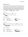
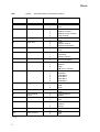
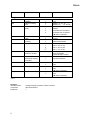
GSI ONLINE for Leica TPS M. Mueller Advanced User Guide Geosystems Introduction Controlling electronic Total Stations with remote interface devices opens a big, new section in the world of surveying applications. Exchanging data and configurations between instruments and computers or transferring data directly to a data logger highly enhances the flexibility and functionality of Leica’s sensors. The latest TPS Total Stations, as well as previous series support a large set of interfacing commands, to allow direct user access via RS232 serial interface. The Leica Geo Serial Interface (GSI) is a general purpose, serial data interface for bi-directional communication between TPS Total Stations and computers. GSI uses a simple command structure to read/write values from/to the sensor. Global and instrument specific word indexes (WI) are used to specify various data types. Depending on the type of Total Station used, GSI provides a specific set of commands considering the instrument series functionality. In addition to the former online reference guide „WILD INSTRUMENTS ONLINE“, this User Guide focuses the latest Leica Series of Total Stations TPS100/300/700/1000/1100. We have designed this guide as a simple command listing and therefore basic aspects of serial data communications will not be covered. For detailed information and advice on GSI communication, we strongly recommend to consult the „WILD INSTRUMENTS ONLINE“. Marco Mueller Business Area TPS 2 Table of contents GSI Data Format............................................................................................. 4 GSI Block Information ..................................................................................... 5 Online Command Structure............................................................................. 6 TPS100 Commands........................................................................................ 7 SET ..................................................................................................... 8 CONF ................................................................................................ 10 PUT ................................................................................................... 12 GET ................................................................................................... 13 Remote Stake out.............................................................................. 14 Warning and Errors ........................................................................... 15 TPS300/700 Commands............................................................................... 16 SET ................................................................................................... 17 CONF ................................................................................................ 20 PUT ................................................................................................... 23 GET ................................................................................................... 25 Warning and Errors ........................................................................... 27 TPS1000/1100 Commands ........................................................................... 28 SET ................................................................................................... 29 CONF ................................................................................................ 31 PUT ................................................................................................... 33 GET ................................................................................................... 34 Telescope positioning ........................................................................ 36 Warning and Errors ........................................................................... 37 3 GSI Data Format GSI Data Format Data transmitted trough GSI interface is composed in a sequence of blocks, ending with a terminator (CR or CR/LF). Every block (see the GSI8 example below) starts with a two character WI code, specifying the data type within this block. So far, a GSI8 block consists of totally 15 characters, including 7 information characters (e.g. WI, sign) and 8 (GSI8) data characters. Since data had become larger than 8 characters, we have introduced an enhanced 16 character data format, called GSI16. This new format size considers large scaled values, such as UTM coordinates, large alphanumeric codes, attributes or pointnumbers. Following, a GSI8 example showing a sequence of three blocks, containing pointnumber (11), easting coordinate (81) and northing coordinate (82). Example 2, shows a GSI16 block sequence with pointnumber (11), horizontal (21) and vertical (22) angle. Example GSI8: 110001+0000A110 81..00+00005387 110002+0000A111 81..00+00007586 110003+0000A112 81..00+00007536 110004+0000A113 81..00+00003839 110005+0000A114 81..00+00001241 ← 8ch.→ 82..00-00000992 82..00-00003031 82..00-00003080 82..00-00003080 82..00-00001344 GSI8 Datablock Structure: Pos.1-2: Pos.3-6: Pos.4: Pos.8-15: Pos.16: Word Index (WI) Information related to data Sign GSI8 data (8 digits) Blank (=separating character) e.g. “11”; WI code e.g. “0002”; number of lines e.g. + or e.g. “0000A113”; Pointnumber Example GSI16: 110001+000000000PNC0055 21.002+0000000013384650 110002+000000000PNC0056 21.002+0000000012802530 110003+000000000PNC0057 21.002+0000000011222360 110004+000000000PNC0058 21.002+0000000010573550 110005+000000000PNC0059 21.002+0000000009983610 ← 16 char. → 22.002+0000000005371500 22.002+0000000005255000 22.002+0000000005433800 22.002+0000000005817600 22.002+0000000005171400 GSI16 Datablock Structure: Pos.1-2: Pos.3-6: Pos.4: Pos.8-23: Pos.16/24: 4 Word Index (WI) Information related to data Sign GSI16 data (16 digits) Blank (=separating character) e.g. “11”; WI code e.g. “0002”; number of lines e.g. + or e.g. “000000000PNC0058”; Pointnumber GSI Bock Information GSI Block Information Position Explanation Applicable for 3 No significance All words 4 AUTOMATIC INDEX INFORMATION 0: Automatic index OFF 1: Automatic index OPERATING 3: Automatic index OPERATING All words containing angle information 5 INPUT MODE 0: Original measured values transferred from the instrument 1: Manual input from keyboard 2: Measured value, Hz-Correction ON 3: Measured value, Hz-Correction OFF 4: Result of special function Measured data 6 UNITS 0: 1: 2: 3: 4: 5: 6: 7: 8: Measured data Meter (last digit: 1mm) Feet (last digit: 1/1000ft) 400 gon 360° decimal 360° sexagesimal 6400 mil Meter (last digit: 1/10mm) Feet (last digit: 1/10‘000ft) Meter (last digit: 1/100mm) SIGN +: -: Positive value Negative value 7 8-15 (8-23) Measured data DATA Data includes a sequence of 8(16) numerical or alphanumerical characters. Measured data Note that certain data blocks are allowed to carry more than 1 value (e.g. PPM/MM). Those data are automatically transferred with a sign before each single value. 16 (24) SEPARATING CHARACTER _: Blank [Tab.1]; [Source: WILD INSTRUMENTS ONLINE; 1988] 5 All words Online Command Structure Online Command Structure GSI online commands represent a simple syntax structure consisting of four basic commands. To access a wide range of settings or values, commands can be enhanced with a limited sequence of word indexes (WI) and parameters. Following, a short summary explaining the meaning of the basic commands continued with some examples. • • • • • SET CONF PUT GET/I/… GET/M/… Set instrument parameters Read internal parameter settings Write/change values within the Total station Get instant values from the Total Station (last valid value) Release measurement and get measured values from the Total Station Examples: SET commands SYNTAX: EXAMPLE: RESPONSE: SET/<set spec>/<parameter><CR/LF> SET/30/0 ? Instrument BEEP: CONF commands SYNTAX: EXAMPLE: RESPONSE: SET/30/0 SET/30/1 CONF/<conf spec><CR/LF> CONF/30 0030/000 Above CONF/30 reads the BEEP setting PUT commands SYNTAX: EXAMPLE: RESPONSE: CONFIRMATION: Beep disabled Beep enabled PUT/11… .+00000012 è PtNo “1234” Make sure you put a space (_), behind <Value>! GET commands SYNTAX: EXAMPLE: RESPONSE: GET/n/WI<get spec><CR/LF> GET/M/WI21 21.102+12149400 Read Hz-Angle value Read Hz-,and V-Angles 6 0030/0000 0030/0001 PUT/<put spec> <Value>_<CR/LF> PUT/11… .+00000012 ? <CR/LF> Writes Pointnumber F OFF (disable) ON (enable) GET/I/WI21 GET/I/WI21/WI22; è 21.104+12149400 è 21.104+12149400 è 22.104+08832420 TPS100 TPS100 Series The TPS100 Series were introduced in 1996/97. These Total Stations were the first series supporting an enhanced set of GSI interfacing commands. The additional functionality conducted to increasing operational benefit, compared to its predecessor TC500 which is described in the WILD INSTRUMENTS ONLINE, Appendix E. Supported Instruments: • TC403L, TC600, TC800 (Firmware Version 2.13 and higher) • TC605/L, TC805/L TC905/L (collectively the “TCx05” series) The following command listing is split into separate sections for each basic command (SET, CONF, PUT, GET). Some of the listed features may require specially equipped instruments (e.g. instruments with Laser Plummet or EGL). For detailed description of single functions, we recommend to consult the corresponding User Manual. Low Level commands SYNTAX: <command>CR/LF RESPONSE: ? <Command>: a b c Powers on the instrument Powers off the instrument Clears a distance measurement Restrictions: 1) Applies to TCx05 instruments only 2) Applies to TCx00/403 instruments only 3) Applies to instruments equipped with EGL (Electronic Guide Light) only 4) Applies to instruments equipped with Laser Plummet only 7 TPS100 SET Syntax: SET/<SET SPEC>/<Parameter><CR/LF> <SET SPEC> FUNCTION 30 BEEP 32 Display contrast 34 BEEP @ 90° 40 Angle UNIT 41 Distance UNIT 44 V angle READING 49 1) Time/Date format 50 Angle rounding 70 Baudrate 71 Parity 73 Terminator 76 Data recording device EGL activity 80 3) 81 3) 95 102 AutoOFF 4) [… cont.] 8 EGL intensity Laser plummet <PARAMETER> 0 1 0 1 2 3 0 1 0 1 2 0 1 0 1 2 0 1 0 1 2 0 1 2 3 4 5 0 1 2 0 1 0 1 0 1 0 1 2 0 1 0 1 SETTING OFF ON Low contrast Medium contrast Medium to high contrast High contrast OFF ON GON Degree decimal Degree sexagesimal Meter Feet Zenith Horizontal Slope in percent Form 1 (am/pm) Form 2 (24 hours) Low Medium High (è refer to manual) 300 Baud 600 Baud 1200 Baud 2400 Baud 4800 Baud 9600 Baud None Odd Even CR CR/LF Internal Memory RS232 OFF ON Poor Medium Strong OFF ON OFF ON TPS100 <SET SPEC> 103 4) 135 136 137 138 1) 149 FUNCTION Laser plummet availibility RS232 recording mask Data transfer output format 0 1 0 1 0 1 2 3 RS232 format length Quick code recording Display MASK 0 1 0 1 0 1 2 1) 3 0 160 Setting measured distance to invalid 171 Direction of horizontal circle reading (Hz-Angle) Compensator 177 <PARAMETER> 178 1) Hz compensator 179 1) Hz collimation 0 1 0 1 0 1 0 1 SETTING No Yes Mask1 (11, 21, 22, … .) Mask2 (11,… ., 81, 82, 83) Mask1 Mask2 Activates user format #1 Activates user format #2 (è refer to manual) GSI8 GSI16 Before measurement After measurement WI 11, 21, 22, 31 WI 21, 22, 32, 33 WI 11, 81, 82, 83 WI 11, 41, 32, 87 Set distance (WI31,32,33) and coordinates (WI81,82,83) to invalid Clockwise Counterclockwise OFF ON OFF ON (è refer to manual) OFF ON (è refer to manual) [Tab.2] Example: Intended action: Command: Response: 9 Change Display contrast to “HIGH” contrast SET/32/3<CR/LF> ? TPS100 CONF Syntax: CONF/<CONF SPEC><CR/LF> <CONF SPEC> FUNCTION 30 BEEP 32 Display contrast 34 BEEP @ 90° 40 Angle UNIT 41 Distance UNIT 44 V angle READING 49 1) Time/Date format 50 Angle rounding 70 Baudrate 71 Parity 73 Terminator 76 Data recording device EGL activity 80 81 3) 3) 90 91 [… cont.] 10 EGL intensity Battery level Instr. Temperature RESPONSE 0030/0000 0030/0001 0032/0000 0032/0001 0032/0002 0032/0003 0034/0000 0034/0001 0040/0000 0040/0001 0040/0002 0041/0000 0041/0001 0044/0000 0044/0001 0044/0002 0049/0000 0049/0001 0050/0000 0050/0001 0050/0002 0070/0000 0070/0001 0070/0002 0070/0003 0070/0004 0070/0005 0071/0000 0071/0001 0071/0002 0073/0000 0073/0001 0076/0000 0076/0001 0080/0000 0080/0001 0081/0000 0081/0001 0081/0002 0090/000n 0091/00nn CONFIGURATION OFF ON Low contrast Medium contrast Medium to high contrast High contrast OFF ON GON Degree decimal Degree sexagesimal Meter Feet Zenith Horizontal Slope in percent Form1 Form2 (è refer to manual) low medium high 300 Baud 600 Baud 1200 Baud 2400 Baud 4800 Baud 9600 Baud NONE ODD EVEN CR CR/LF Internal Memory RS232 OFF ON poor medium strong N[1=empty..9=full] nn<100: Temp in °C nn>200: nn-255= temperature in -°C TPS100 <CONF SPEC> FUNCTION 95 AutoOFF 102 4) Laser plummet 103 4) Laser plummet availability RS232 recording mask Data transfer output format 135 136 FORM/n 137 138 1) 149 160 Check format name; n:[1..4] RS232 format length Quick code recording Display MASK 177 Validity of measured distance EDM measuring mode Direction of horizontal circle reading (Hz-Angle) Compensator 178 Hz compensator 179 Hz collimation 180 Instrument Series 181 Instrument Type 182 Firmware version 161 171 [Tab.3] 11 RESPONSE 0095/0000 0095/0001 0102/0000 0102/0001 0103/0000 0103/0001 0135/0000 0135/0001 0136/0000 0136/0001 0136/0002 0136/0003 CONFIGURATION “Format_1” “Format_n” 0137/0000 0137/0001 0138/0000 0138/0001 0149/0000 0149/0001 0149/0002 1) 0149/0003 0160/0000 0160/0001 0161/0000 0161/0001 0171/0000 0171/0001 OFF ON OFF ON Not available Available Mask1 (11, 21, 22, … .) Mask2 (11,… ., 81, 82, 83) Mask1 Mask2 Activates user format #1 Activates user format #2 (è refer to manual) e.g. CONF/FORM/1 -> „GSI 2“ GSI8 GSI16 Before measurement After measurement WI 11, 21, 22, 31 WI 21, 22, 32, 33 WI 11, 81, 82, 83 WI 11, 41, 32, 87 Invalid DIST Valid DIST IR Fine mode IR Rapid mode Clockwise Counterclockwise 0177/0000 0177/0001 0178/0000 0178/0001 0179/0000 0179/0001 0180/0004 0180/0006 0180/0008 0180/0009 0181/0000 0181/0001 0182/0217 OFF ON OFF ON OFF ON) TC403 TC600/605 TC800/805 TC905 T (Theodolite) TC (Total Station) e.g. Version 2.17 TPS100 PUT Syntax: SET/<PUT SPEC>/<Parameter>_<CR/LF> <PUT SPEC> FUNCTION Access/Example 11 Set Pointnumber PUT/11… .+00001234_<CR/LF> è puts PtID “1234” 21 Hz Angle PUT/21… n+10000000_<CR/LF> n[2..4]; angle units must be specified è for n=2; puts Hz=”100.0000 gon” 58 Prism const PUT/58… .+00000200_<CR/LF> è puts reflector constant to “20mm” 59 PPM PUT/59.… +02200000_<CR/LF> è puts PPM correction to “220” 84 Station Easting PUT/84… n+00100000_<CRLF> n[0..1]; distance unit must be specified è for n=0; puts Easting=”100.000 m” 85 Station Northing PUT/85… n+00100000_<CRLF> n[0..1]; distance unit must be specified è for n=0; puts Northing=”100.000 m” 86 Station Elevation PUT/86… n+00045000_<CRLF> n[0..1]; distance unit must be specified è for n=0; puts Elevation=”45.000 m” 87 Reflector height PUT/87… n+00001700_<CRLF> n[0..1]; distance unit must be specified è for n=0; puts hr=”1.700 m” 88 Instrument height PUT/88… n+00001500_<CRLF> n[0..1]; distance unit must be specified è for n=0; puts hi=”1.500 m” [Tab.4] 12 TPS100 GET Syntax: GET/n/WI<GET SPEC>/<Parameter><CR/LF> <GET SPEC> FUNCTION Access/Example 11 Pointnumber GET/M/WI11<CR/LF>; e.g. 11… .+00000H66 è PtNo=“H66“ 21 Hz Angle GET/M/WI21<CR/LF>; e.g. 21.102+17920860 è Hz „179.086“ gon 22 Vertical Angle GET/M/WI22<CR/LF>; e.g. 22.102+07567500 è V: „75.675“ gon 31 Slope distance GET/M/WI31<CR/LF>; e.g. 31..00+00003387 è Sdist: „3.387“ m 32 Horizontal distance GET/M/WI32<CR/LF>; e.g. 32..00+00003198 è Hdist: „3.198“ m 33 Height difference GET/M/WI33<CR/LF>; e.g. 33..00+00001119 è Hdiff: „1.119“ m 51 PPM and Prism constant GET/I/WI51; e.g. 51… .+0220+002 è PPM „220“ and Prism const „2“ mm 58 Prism constant GET/I/WI58; e.g. 58..16+00000020 è Prism „2“ mm 59 PPM GET/I/WI59; e.g. 59..16+02200000 è PPM „220“ 81 Target Easting (E) GET/M/WI81; e.g. 81..00+01999507 è E: “1999.507”m 82 Target Northing (N) GET/M/WI82; e.g. 82..00-00213159 è N: “-2139.159”m 83 Target Elevation (H) GET/M/WI83; e.g. 83..00+00032881 è H: “32.881”m 84 Station Easting (E0) GET/I/WI84; e.g. 84..11+00393700 è E: “393.700”m 85 Station Northing (N0) GET/I/WI85; e.g. 85..11+06561220 è N: “6561.220”m 86 Station Height (H0) GET/I/WI86; e.g. 86..11+00065618 è H: “65.618”m 87 Reflector height (hr) GET/I/WI87; e.g. 87..11+00001700 è hr: “1.700” m 88 Instrument height (hi) GET/I/WI88; e.g. 88..11+00001550 è hi: “1.550” m read date GETDATE; (dd:mm:yy) è 07/02/00 read time GETTIME; (hh:mm:ss) è 04:06:58p GETDATE GETTIME [Tab.5] 13 1) 1) TPS100 Remote Stake Out The TCx05 series support a remote set-out method for surveyors using handheld or external recording devices. Stake out data can be transferred from via RS232 interface to the instrument’s onboard Remote Stake Out application. The following procedure describes a possible way for successful field stake out. [Note: “_” represents a space character] • Remote Set Station Start Remote S/O SETOUT<CR/LF> Calls onbard S/O Set Station Pointnumber PUT/16… .+000S7000_<CRLF> e.g. “S7000” Set Station Easting PUT/84… 0+00100000_<CRLF> e.g. “100.000“[m] Set Station Northing PUT/85… 0+00100000_<CRLF> e.g. “100.000“[m] SetStation Height PUT/86… 0+00050000_<CRLF> e.g. “50.000“[m] Set Instrument Height PUT/88… 0+00001500_<CRLF> e.g. “1.500” [m] PUT/21… 2+00000000_<CRLF> e.g. “0.000” gon (respectively Hz=0) • Remote Set Orientation Set Hz-Orientation • Remote Target Point setting out Set Target Pointnumber PUT/11… .+000S7000_<CRLF> e.g. “S7000” Set stakeout bearing PUT/24… 2+00102000_<CRLF> e.g. “102.000“[m] Set stakeout distance PUT/34… 0+00103000_<CRLF> e.g. “103.000“[m] Set stakeout height PUT/83… 0+00053000_<CRLF> e.g. “53.000“[m] Set Reflector height PUT/87… .+00001500_<CRLF> e.g. “1.500” [m] Release DIST or ALL key to measure a distance Terminating remote S/O X<CR/LF> Quits remote S/O For further information, please refer to the corresponding instrument manual. Refer also to „Basic Knowledge“ BK99/44. 14 TPS100 Warnings/Errors Message ID Meaning Possible reasons @W100 Instrument busy Any other device is still interfacing the instrument; check interfacing priorities @W127 Invalid command The string sent to the TC could not be decoded properly or does not exist; check the syntax, or … Input buffer overflow (max. 100 characters) @W139 EDM error The EDM could not proceed the requested measurement; no or weak signal; Check EDM mode and target @W158 One of the instruments sensor corrections could not be assigned. Instrument is not stable or levelled; Tilt is out of range (e.g. when tilt sensor is out of range) @E101 Value out of range Check parameter range @E103 Invalid Value No valid value; Check parameter range @E112 Battery low Low Battery; check voltage @E114 Invalid command No valid command; check the syntax @E117 Initialisation error Contact service @E119 Temperature out of range Refer to manual for temperature range @E121 Parity error Wrong parity set; check Com-Port settings @E122 RS232 time-out The instrument was waiting for a response for the last 2 seconds @E124 RS232 overflow RS232 overflow; check Com-Port settings @E151 Compensator error Inclination Error; check instrument setup or switch of the compensator @E155 EDM intensity Weak signal; target is most likely outside the field of view @E156 EDM system error Contact service @E158 One of the instruments sensor corrections could not be assigned. Instrument is not stable, not levelled or suffering of vibration; Tilt is out of range (e.g. when tilt sensor is out of range); Level instrument or switch off compensator @E190 General hardware error Contact service @E197 Initialization error Contact service [Tab.6] 15 TPS300/700 TPS300/700 Series The TPS300 and TPS700 series were introduced in 1998/99. Featuring the latest generation technology, these instruments have further increased their interfacing capabilities. Considering the new firmware and application platform, lots of new commands have been added or existing commands being changed compared to its predecessors, the TPS100 Total Stations. However, basic functions use the same commands and therefore most of the existing TPS100 interfacing applications will still support the new TPS300/700 series. Supported Instruments: • TC302, TC303, TC305, TC307 • TCR302, TCR303, TCR305, TCR307 • TC702, TC703, TC705 • TCR702, TCR703, TCR705 The following command listing is split into separate sections for each basic command (SET, CONF, PUT, GET). Some of the listed features may require specially equipped instruments (e.g. Reflectorless EDM è RL). For detailed description of single functions, we recommend to consult the corresponding User Manual. Low Level commands SYNTAX: <command>CR/LF SYNTAX: BEEP/<value> <Command>: <Value>: a b c BEEP/0 BEEP/1 BEEP/2 Restrictions: 1) TCR models ONLY 2) Instruments equipped with EGL3 only 16 Powers on the instrument Powers off the instrument Clears a distance measurement Short beep Long beep Alarm beep (short beep, 3 times) TPS300/700 SET Syntax: SET/<SET SPEC>/<Parameter><CR/LF> <SET SPEC> FUNCTION 30 BEEP 31 Display illumination 32 Display contrast 34 BEEP @ 90° 35 2) EGL activity 36 1) Laser Pointer 40 Angle UNIT 41 Distance UNIT 42 Temperature UNIT 43 Pressure UNIT 50 Angle; displayed decimals [… cont.] 17 <PARAMETER> 0 1 2 0 1 2 3 [0..100] 0 50 100 0 1 0 1 2 3 0 1 0 1 2 3 4 0 1 2 3 4 0 1 0 1 2 3 4 5 6 0 1 2 3 4 SETTING OFF Medium Loud Off Low Medium High è [range] Low contrast Medium contrast High contrast OFF ON OFF Low Medium High OFF ON GON Degree decimal Degree sexagesimal Mils radiant Meter US Feet, decimal Intl. Feet, decimal US Feet/Inch Intl. Feet/Inch Degree Celcius Degree Fahrenheit hPa MmHg Mbar PSI InchHg Atm Torr ,0000 ,n000 ,nn00 ,nnn0 ,nnnn TPS300/700 <SET SPEC> FUNCTION 51 Distance; displayed decimals 55 55 70 Angle rounding Distance rounding Baudrate 71 Parity 73 Terminator 75 Protocol 76 78 95 Data recording device Timeout delay AutoOFF 102 Laser plummet 104 Laser plummet pulse rate 105 Laser plummet intensity 106 Display heat 120 Orientation face definition Recording mask 135 136 137 [… cont.] 18 Output format number RS232 format length <PARAMETER> 0 1 2 3 4 [0..10] [0..10] 0 1 2 3 4 5 6 0 1 2 0 1 0 1 0 1 [0..50] 0 1 2 0 1 [0..100] 0 100 [0..100] 0 100 0 1 0 1 [0..8] [0..127] 0 1 SETTING ,000 ,n00 ,nn0 ,nnn ,nnn(n) e.g. n=3: 0.3, 0.6, 0.9, … e.g. n=3: 0.3, 0.6, 0.9, … 300 Baud 600 Baud 1200 Baud 2400 Baud 4800 Baud 9600 Baud 19200 Baud None Odd Even CR CR/LF Off On Internal Memory RS232 Increase of 10ms/unit Off On Sleep mode Off On [range] permanent High pulse rate [range] Low bright Off On Face I Face II [range] (è refer to manual) [range] (è refer to manual) GSI8 GSI16 TPS300/700 <SET SPEC> FUNCTION 138 Quick code recording Setting measured distance to invalid 0 1 0 161 EDM modes (SET/161/n) 171 Direction of horizontal circle reading (Hz-Angle) Compensator 0 1 2 3 4 5 1) 6 1) 7 8 1) 9 10 0 1 160 173 178 Standing axis correction 179 Hz collimation [Tab.7] 19 <PARAMETER> 0 1 0 1 0 1 SETTING Before measurement After measurement Setting WI31,32,33 and coordinates WI81,82,83 to invalid; (CONT variables only; contact a TPS product manager) IR Standard IR Fast n.a. n.a. n.a. IR Tracking RL Long (with prisms) RL Short n.a. RL Tracking IR Tape Clockwise Counterclockwise OFF ON OFF (1-Axis) ON (2-Axis) (è refer to manual) OFF ON (è refer to manual) TPS300/700 CONF Syntax: CONF/<CONF SPEC><CR/LF> <CONF SPEC> FUNCTION 30 BEEP 31 Display illumination 32 Display contrast 34 BEEP @ 90° 35 2) EGL activity 36 1) Laser Pointer 40 Angle UNIT 41 Distance UNIT 42 Temperature UNIT 43 Pressure UNIT 50 Angle; displayed decimals [… cont.] 20 RESPONSE 0030/0000 0030/0001 0030/0002 0031/0000 0031/0001 0031/0002 0031/0003 0032/0nnn 0034/0000 0034/0001 0035/0000 0035/0001 0035/0002 0035/0003 0036/0000 0036/0001 0040/0000 0040/0001 0040/0002 0040/0003 0040/0004 0041/0000 0041/0001 0041/0002 0041/0003 0041/0004 0042/0000 0042/0001 0043/0000 0043/0001 0043/0002 0043/0003 0043/0004 0043/0005 0043/0006 0050/0000 0050/0001 0050/0002 0050/0003 0050/0004 CONFIGURATION Off Normal Loud Off Low Medium High n:[0..100] 0: lowest contrast 50: Medium contrast 100: Highest contrast Off On Off Low Medium High Off On Gon Degree decimal Degree sexagesimal Mil Radiant Meter US Feet, decimal Intl. Feet, decimal US Feet/Inch Intl. Feet/Inch Degree Celcius Degree Fahrenheit hPa mmHg mBar PSI InchHg Atm Torr ,0000 ,n000 ,nn00 ,nnn0 ,nnnn TPS300/700 <CONF SPEC> FUNCTION 51 Distance; displayed decimals 55 56 70 Angle rounding Distance rounding Baudrate 71 Parity 73 Terminator 75 Protocol 76 78 90 Data recording device Timeout delay Battery level 91 95 Temperature Auto-OFF 102 Laser plummet 103 Laser plummet availability Laser plummet pulse rate 104 RESPONSE 0051/0000 0051/0001 0051/0002 0051/0003 0051/0004 0055/00nn 0056/00nn 0070/0000 0070/0001 0070/0002 0070/0003 0070/0004 0070/0005 0070/0006 0071/0000 0071/0001 0071/0002 0073/0000 0073/0001 0075/0000 0075/0001 0076/0000 0076/0001 [0..50] 0090/00nn 0091/0nnn 0095/0000 0095/0001 0102/0000 0102/0001 0103/0000 0103/0001 0104/0nnn 105 Laser plummet intensity 0105/0nnn 106 Display heat 120 Orientation face definition 0106/0000 0106/0001 0120/0000 0120/0001 [… cont.] 21 CONFIGURATION ,000 ,n00 ,nn0 ,nnn ,nnn(n) N:[1..10] N:[1..10] 300 Baud 600 Baud 1200 Baud 2400 Baud 4800 Baud 9600 Baud 19200 Baud NONE ODD EVEN CR CR/LF Off On Internal Memory RS232 Increase of 10ms/unit n:[0..10] 0: Empty 10: Full [0..±100] °C Off On Off On Not available Available N: [0..100] 0: Permanent 100: High pulse rate N: [0..100] 0: Low 100: bright Off On Face I Face II TPS300/700 <CONF SPEC> FUNCTION 122 Orientation face status (face of last measurement) RS232 recording mask Output format number RS232 recording length Quick code recording Display MASK Validity of measured distance EDM modes (SET/161/n) 135 136 137 138 138 160 161 170 Detect current face 171 Direction of horizontal circle reading (Hz-Angle) Compensator 173 178 Standing axis correction 179 Hz collimation [Tab.8] 22 RESPONSE CONFIGURATION 0122/0000 0122/0001 0135/000n Face I Face II (è refer to manual) N: [0..8] 0136/0nnn n: [0..127] 0137/0000 0137/0001 0138/0000 0138/0001 0138/000n 0160/0000 0160/0001 0161/0000 0161/0001 0161/0005 1) 0161/0006 1) 0161/0007 1) 0161/0009 0161/0010 0170/0000 0170/0001 GSI8 GSI16 Before measurement After measurement N: [0..8] Distance invalid Distance valid IR Standard IR Fast IR Tracking RL Long (with prisms) RL Short RL Tracking IR Tape Face I Face II (è refer to manual) Clockwise Counterclockwise 0171/0000 0171/0001 0173/0000 0173/0001 0178/0000 0178/0001 0179/0000 0179/0001 OFF ON OFF (1-Axis) ON (2-Axis) (è refer to manual) OFF ON (è refer to manual) TPS300/700 PUT Syntax: SET/<PUT SPEC>/<Parameter>_<CR/LF> <PUT SPEC> FUNCTION Access/Example 11 Set Pointnumber 16 21 Station Pointnumber Hz Angle 41 Code-Block ID 42 Information 1 43 Information 2 44 Information 3 45 Information 4 46 Information 5 47 Information 6 48 Information 7 49 Information 8 58 Prism const PUT/11… .+00001234_<CR/LF> è puts PtID “1234” PUT/16....+0000A100_<CR/LF> è puts StNr “A100” PUT/21… n+10000000_<CR/LF> n[2..4]; angle units must be specified è for n=2; puts Hz=”100.0000 gon” PUT/41....+0000TREE_<CR/LF> è puts code value “TREE” PUT/42....+000012.4_<CR/LF> è puts info value “12.4” PUT/43....+0000CAT2_<CR/LF> è puts info value “CAT2” PUT/44....+000000NN_<CR/LF> è puts info value “NN” PUT/45....+000000NN_<CR/LF> è puts info value “NN” PUT/46....+000000NN_<CR/LF> è puts info value “NN” PUT/47....+000000NN_<CR/LF> è puts info value “NN” PUT/48....+000000NN_<CR/LF> è puts info value “NN” PUT/49....+000000NN_<CR/LF> è puts info value “NN” PUT/58… .+00000200_<CR/LF> è puts reflector constant to “20mm” 59 PPM PUT/59.… +02200000_<CR/LF> è puts PPM correction to “220” 84 Station Easting PUT/84… n+00100000_<CRLF> n[0..1]; distance unit must be specified è for n=0; puts Easting=”100.000 m” 85 Station Northing PUT/85… n+00100000_<CRLF> n[0..1]; distance unit must be specified è for n=0; puts Northing=”100.000 m” 86 Station Elevation PUT/86… n+00045000_<CRLF> n[0..1]; distance unit must be specified è for n=0; puts Elevation=”45.000 m” 87 Reflector height PUT/87… n+00001700_<CRLF> n[0..1]; distance unit must be specified è for n=0; puts hr=”1.700 m” [… cont.] 23 TPS300/700 <PUT SPEC> FUNCTION Access/Example 88 Instrument height 560 Time: [hh.mm.ss] 561 Date: [mm.dd] 562 Year: [yyyy] 912 Station Pointnumber PUT/88… n+00001500_<CRLF> n[0..1]; distance unit must be specified è for n=0; puts hi=”1.500 m” PUT/560..6+00113059_<CRLF> è “11:30:59” PUT /561..6+00020800_<CRLF> th è February 8 2000 PUT/562...+00002000_<CRLF> è year “2000” PUT/912...+0000ST15_<CRLF> è puts Station PtID “ST15” [Tab.9] 24 TPS300/700 GET Syntax: GET/n/WI<GET SPEC>/<Parameter><CR/LF> <GET SPEC> FUNCTION Access/Example 11 Pointnumber 12 Serial number 13 Instrument type 16 21 Station Pointnumber Date [DD.MM.YYYY] Time [MM.DD.hh.mm] Horizontal Angle 22 Vertical Angle 31 Slope distance 32 Horizontal distance 33 Height difference 41 Code-Block ID 42 Information 1 43 Information 2 44 Information 3 45 Information 4 46 Information 5 47 Information 6 48 Information 7 49 Information 8 58 Prism constant 59 PPM GET/M/WI11<CR/LF>; e.g. 11… .+00000H66 è PtNo=“H66“ GET/I/WI12<CR/LF>; e.g. 12....+00640054 è S.No. “640054” GET/I/WI13<CR/LF>; 13....+00TCR305 è Instr. “TCR305” GET/I/WI16; e.g. 16....+00000100” è St.No. “100” GET/I/WI17; e.g. 17....+08022000 th è “Feb. 8 2000” GET/I/WI19; e.g. 19....+02081029 th è “Feb. 8 ; 10:29” GET/M/WI21<CR/LF>; e.g. 21.102+17920860 è Hz „179.086“ gon GET/M/WI22<CR/LF>; e.g. 22.102+07567500 è V: „75.675“ gon GET/M/WI31<CR/LF>; e-g. 31..00+00003387 è Sdist: „3.387“ m GET/M/WI32<CR/LF>; e.g. 32..00+00003198 è Hdist: „3.198“ m GET/M/WI33<CR/LF>; e.g. 33..00+00001119 è Hdiff: „1.119“ m GET/I/WI41<CR/LF>; e.g. 41....+00000013 è Code: „13“ m GET/I/WI42<CR/LF>; e.g. 42....+000TREES è Info1: „TREES“ GET/I/WI43<CR/LF>; e.g. 43....+000004.5 è Info2: „4.5“ GET/I/WI44<CR/LF>; e.g. 44....+00CAT.02 è Info3: „CAT.02“ GET/I/WI45<CR/LF>; e.g. 45....+000000NN è Info4: „NN“ GET/I/WI46<CR/LF>; e.g. 46....+000000NN è Info5: „NN“ GET/I/WI47<CR/LF>; e.g. 47....+000000NN è Info6: „NN“ GET/I/WI48<CR/LF>; e.g. 48....+000000NN è Info7: „NN“ GET/I/WI49<CR/LF>; e.g. 49....+000000NN è Info8: „NN“ GET/I/WI58; e.g. 58..16+00000020 è Prism „2“ mm GET/I/WI59; e.g. 59..16+02200000 è PPM „220“ 17 19 [… cont.] 25 TPS300/700 <GET SPEC> FUNCTION Access/Example 81 Target Easting (E) GET/M/WI81; e.g. 81..00+01999507 è E: “1999.507”m 82 Target Northing (N) GET/M/WI82; e.g. 82..00+00213159 è N: “2139.159”m 83 Target Elevation (H) GET/M/WI83; e.g. 83..00-00032881 è H: “32.881”m 84 Station Easting (E0) GET/I/WI84; e.g. 84..11+00393700 è E: “393.700”m 85 Station Northing (N0) GET/I/WI85; e.g. 85..11+06561220 è N: “6561.220”m 86 Station Height (H0) GET/I/WI86; e.g. 86..11+00065618 è H: “65.618”m 87 Reflector height (hr) GET/I/WI87; e.g. 87..11+00001700 è hr: “1.700” m 88 Instrument height (hi) 531 560 Atmos. correction: pressure Coefficient of refraction Time: [hh.mm.ss] 561 Date: [mm.dd] 562 Year: [yyyy] 590 913 SW-Version: Application SW-Version: Operating system SW-Version: OS interface SW-Version: GEOCOM SW-Version: Gsi communication SW-Version: Edm Device Job 914 Operator GET/I/WI88; e.g. 88..11+00001550 è hi: “1.550” m GET/I/WI531; e.g. 531.16+10130000 è “1013” GET/I/WI538; e.g. 538.16+00001300 è “1.300” GET/I/WI560; e.g. 560..6+00105018 è “10:50:18” GET/I/WI561; e.g. 561..6+00020800 è “2.8.2000” GET/I/WI562; e.g. 562...+00002000 è year “2000” GET/I/WI590; e.g. 590..6+00021000 è “V2.10” GET/I/WI591; e.g. 591..6+00020000 è “V2.00” GET/I/WI592; e.g. 592..6+00010000 è “V1.00” GET/I/WI593; e.g. 593..6+00022000 è “V2.20” GET/I/WI594; e.g. 594..6+00010000 è “V1.00” GET/I/WI595; e.g. 595..6+00011100 è “V1.11” GET/I/WI913; e.g. 913...+BLDG.A12 è “BLDG.A12” GET/I/WI914; e.g. 914...+0MM-3519 è “MM-3519” 538 591 592 593 594 595 [Tab.10] 26 TPS300/700 Warnings/Errors Message ID Meaning Possible reasons @W100 Instrument busy Any other device is still interfacing the instrument; check interfacing priorities @W127 Invalid command The string sent to the TC could not be decoded properly or does not exist; check the syntax, or … Input buffer overflow (max. 100 characters) @E139 EDM error The EDM could not proceed the requested measurement; no or weak signal; Check EDM mode and target @E158 One of the instruments sensor corrections could not be assigned. Instrument is not stable, not levelled or suffering of vibration; Tilt is out of range (e.g. when tilt sensor is out of range); Level instrument or switch off compensator [Tab.11] 27 TPS1000/1100 TPS1000/1100 Series The TPS1000 and its successor TPS1100 series represent the very high end level of Leica’s Total Station products. Functionality has increased and instruments do more and more support customized remote control options. Thus controlling instruments with GSI commands has come to a technical limit. However, to provide access to all implemented functions, a new interfacing tool has been developed, called GEOBASIC. As GEOBASIC will not be covered within this reference guide, we kindly ask you to consult the corresponding GEOBASIC USER MANUAL, for further information on GEOBASIC. You will find the manual on every CD-ROM’s delivered with TPS Total Stations. Following, the complete set of GSI ONLINE commands providing access to TPS1000/1100 GSI functions. Supported Instruments (TPS1000 Series) • TC1100/L, TC1500/L, TC1700/L, TC1800/L • TCM1100/L, TCM1800/L • TCA1100/L, TCA1800/L Supported Instruments (TPS1100 Series) • TC1101, TC1102, TC1103, TC1105 • TCR1101, TCR1102, TCR1103, TCR1105 • TCM1101, TCM1102, TCM1103, TCM1105 • TCRM1101, TCRM1102, TCRM1103, TCRM1105 • TCA1101, TCA1102, TCA1103, TCA1105 • TCRA1101, TCRA1102, TCRA1103, TCRA1105 For standard recording, the instrument needs to be activated in any “Measure&Record” mode. To avoid unnecessary miscommunication, we therefore recommend to enable the autostart function for remote control applications. Low Level commands SYNTAX: <command>CR/LF SYNTAX: BEEP/<value> <Commands>: Example: 28 a b c BEEP/0 BEEP/1 BEEP/2 Powers on the instrument Powers off the instrument Clears a distance measurement Short beep Long beep Alarm beep (TPS1000 series only!) TPS1000/1100 SET Syntax: SET/<SET SPEC>/<Parameter><CR/LF> <SET SPEC> FUNCTION 30 BEEP 31 32 Display (DSP) and Crosshairs (X-hairs)illumination Display contrast 35 EGL 40 Angle UNIT 41 Distance UNIT 42 Temperature UNIT 43 Pressure UNIT 50 Angle; displayed decimals 51 Distance; displayed decimals 71 Parity 73 Terminator [… cont.] 29 <PARAMETER> 0 1 2 0 1 2 3 0 1 2 3 0 1 0 1 2 3 0 1 2 3 4 0 1 0 1 2 3 4 2 3 4 0 1 2 3 4 5 0 1 2 0 1 SETTING OFF Medium Loud Off DSP on, X-hairs low DSP on, X-hairs medium DSP on, X-hairs bright Low Low-Medium Medium-High High Off On Gon Degree decimal Degree, sexagesimal Mils Meter US Feet, decimal Intl. Feet, decimal US Feet/Inch Intl. Feet/Inch °C °F hPa mmHg mbar PSI inchHg 123.12 123.123 123.1234 or … max. accuracy 123. 123.1 123.12 123.123 123.1234 123.12345 None Odd Even CR CR/LF TPS1000/1100 <SET SPEC> FUNCTION 75 Protocol 76 Data recording device AutoOFF 95 137 160 RS232 format length Setting measured distance to invalid 161 EDM modes (SET/161/n) 173 Compensator [Tab.12] 1) 2) TPS1000 only TPS1100 only 30 <PARAMETER> 0 1 0 1 0 1 0 1 0 0 1 2 3 4 5 6 7 9 10 11 12 0 1 SETTING Without GSI Memory card RS232 interface Off On GSI8 GSI16 Setting WI31,32,33 and coordinates WI81,82,83 to invalid IR Standard IR Fast IR Average 1) 2) IR Precise /Standard IR Tracking IR Rapid tracking 2) RL Stand. long range 2) RL Standard 2) RL Tracking 1) IR Tape 2) RL Average long range 2) RL Average Off On TPS1000/1100 CONF Syntax: CONF/<CONF SPEC><CR/LF> <CONF SPEC> FUNCTION 30 BEEP 31 32 Display (DSP) and Crosshairs (X-hairs)illumination Display contrast 35 EGL 40 Angle UNIT 41 Distance UNIT 42 Temperature UNIT 43 Pressure UNIT 50 Angle; displayed decimals 51 Distance; displayed decimals 0051/0000 0051/0001 0051/0002 0051/0003 0051/0004 70 Baudrate 0070/0003 0070/0004 0070/0005 0070/0006 [… cont.] 31 RESPONSE 0030/0000 0030/0001 0030/0001 0031/0000 0031/0001 0031/0002 0031/0003 0032/0000 0032/0001 0032/0002 0032/0003 0035/0000 0035/0001 0040/0000 0040/0001 0040/0002 0040/0003 0041/0000 0041/0001 0041/0002 0041/0003 0041/0004 0042/0000 0042/0001 0043/0000 0043/0001 0043/0002 0043/0003 0043/0004 0050/0002 0050/0003 0050/0004 CONFIGURATION OFF Medium Loud Off DSP on, X-hairs low DSP on, X-hairs medium DSP on, X-hairs bright Low Low-Medium Medium-High High Off On Gon Degree decimal Degree, minute, second Mil Meter US Feet, decimal Intl. Feet, decimal US Feet/Inch Intl. Feet/Inch °C °F hPa mmHg mBar PSI InchHg 123.12 123.123 123.1234 or … max. accuracy 123. 123.1 123.12 123.123 123.1234 or … max. accuracy 2400 Baud 4800 Baud 9600 Baud 19200 Baud TPS1000/1100 <CONF SPEC> FUNCTION 71 Parity 73 Terminator 75 Protocol 76 90 Data recording device Battery level 95 AutoOFF 135 137 Recording mask RS232 format length Display MASK Validity of measured distance EDM modes (SET/161/n) 149 160 161 170 Detect current face 171 Direction of horizontal circle reading (Hz-Angle) Compensator 173 182 184 [Tab.13] 32 Software version Active application running RESPONSE CONFIGURATION 0071/0000 0071/0001 0071/0002 0073/0000 0073/0001 0075/0000 0075/0001 0076/0000 0076/0001 0090/000n None Odd Even CR CR/LF Without GSI Memory card Serial interface N:[1..9]; n=1: low 0095/0000 0095/0001 0095/0002 0135/0000 0137/0000 0137/0001 0149/0001 0160/0000 0160/0001 0161/0000 0161/0001 0161/0002 0161/0003 0161/0004 0161/0005 0161/0006 0161/0007 0161/0009 0161/0010 0161/0011 0161/0012 0170/0000 0170/0001 0171/0000 0171/0001 Off On Sleep Mask 1 GSI8 GSI16 Mask 1 Distance/Coords invalid Distance/Coords valid IR Standard IR Fast IR Average 1) 2) IR Precise /Standard IR Tracking IR Rapid tracking 2) RL Stand. long range 2) RL Standard 2) RL Tracking 1) IR Tape 2) RL Average long range 2) RL Average Face I Face II (è refer to manual) Clockwise Counterclockwise 0173/0000 0173/0001 0182/00nn 0184/0000 0184/0001 OFF ON Version n.n No Yes TPS1000/1100 PUT Syntax: SET/<PUT SPEC>/<Parameter>_<CR/LF> <PUT SPEC> FUNCTION Access/Example 11 Set Pointnumber PUT/11… .+00001234_<CR/LF> è puts PtID “1234” 21 Hz Angle PUT/21… n+10000000_<CR/LF> n[2..4]; angle units must be specified è for n=2; puts Hz=”100.0000 gon” 58 Prism const PUT/58… .+00000200_<CR/LF> è puts reflector constant to “20mm” 59 PPM 71 Remark 1 (or Attribute 1) Remark 2 (or Attribute 2) Remark 3 (or Attribute 3) Remark 4 (or Attribute 4) Remark 5 (or Attribute 5) Remark 6 (or Attribute 6) Remark 7 (or Attribute 7) Remark 8 (or Attribute 8) Remark 9 (or Attribute 9) Station Easting PUT/59.… +02200000_<CR/LF> è puts PPM correction to “220” PUT/71....+000012.4_<CR/LF> è puts info value “12.4” PUT/72....+0000CAT2_<CR/LF> è puts info value “CAT2” PUT/73....+000000NN_<CR/LF> è puts info value “NN” PUT/74....+000000NN_<CR/LF> è puts info value “NN” PUT/78....+000000NN_<CR/LF> è puts info value “NN” PUT/76....+000000NN_<CR/LF> è puts info value “NN” PUT/77....+000000NN_<CR/LF> è puts info value “NN” PUT/78....+000000NN_<CR/LF> è puts info value “NN” PUT/79....+000000NN_<CR/LF> è puts info value “NN” PUT/84… n+00100000_<CRLF> è for n=0; puts Easting=”100.000 m” 72 73 74 75 76 77 78 79 84 a) 85 a) 86 Station Northing PUT/85… n+00100000_<CRLF> è for n=0; puts Northing=”100.000 m” a) Station Elevation PUT/86… n+00045000_<CRLF> è for n=0; puts Elevation=”45.000 m” 87 a) Reflector height PUT/87… n+00001700_<CRLF> è for n=0; puts hr=”1.700 m” 88 a) Instrument height PUT/88… n+00001500_<CRLF> è for n=0; puts hi=”1.500 m” [Tab.14] a) For WI84-88; distance unit must be specified with n[0..1]; please refer to page 5. 33 TPS1000/1100 GET Syntax: GET/n/WI<GET SPEC>/<Parameter><CR/LF> <GET SPEC> FUNCTION Access/Example 11 Pointnumber 12 Serial number 13 Instrument type 19 21 Time [MM.DD.hh.mm] Horizontal Angle 22 Vertical Angle GET/M/WI11<CR/LF>; e.g. 11… .+00000H66 è PtNo=“H66“ GET/I/WI12<CR/LF>; e.g. 12....+00640054 è S.No. “640054” GET/I/WI13<CR/LF>; 13....+00TCR305 è Instr. “TCR305” GET/I/WI19; e.g. 19....+02081029 th è “Feb. 8 ; 10:29” GET/M/WI21<CR/LF>; e.g. 21.102+17920860 è Hz „179.086“ gon GET/M/WI22<CR/LF>; e.g. 22.102+07567500 è V: „75.675“ gon 31 Slope distance GET/M/WI31<CR/LF>; e-g. 31..00+00003387 è Sdist: „3.387“ m 32 Horizontal distance GET/M/WI32<CR/LF>; e.g. 32..00+00003198 è Hdist: „3.198“ m 33 Height difference 41 Code-Block ID 42 Information 1 43 Information 2 44 Information 3 45 Information 4 46 Information 5 47 Information 6 48 Information 7 49 Information 8 51 PPM/mm 58 Prism constant GET/M/WI33<CR/LF>; e.g. 33..00+00001119 è Hdiff: „1.119“ m GET/I/WI41<CR/LF>; e.g. 41....+00000013 è Code: „13“ m GET/I/WI42<CR/LF>; e.g. 42....+000TREES è Info1: „TREES“ GET/I/WI43<CR/LF>; e.g. 43....+000004.5 è Info2: „4.5“ GET/I/WI44<CR/LF>; e.g. 44....+00CAT.02 è Info3: „CAT.02“ GET/I/WI45<CR/LF>; e.g. 45....+000000NN è Info4: „NN“ GET/I/WI46<CR/LF>; e.g. 46....+000000NN è Info5: „NN“ GET/I/WI47<CR/LF>; e.g. 47....+000000NN è Info6: „NN“ GET/I/WI48<CR/LF>; e.g. 48....+000000NN è Info7: „NN“ GET/I/WI49<CR/LF>; e.g. 49....+000000NN è Info8: „NN“ GET/I/WI51<CR/LF>; e.g. 51..1.+0000+034 è “0”ppm; “34”mm GET/I/WI58; e.g. 58..16+00000020 è Prism „2“ mm 59 PPM [… cont.] 34 GET/I/WI59; e.g. 59..16+02200000 è PPM „220“ TPS1000/1100 <GET SPEC> FUNCTION Access/Example 71 Remark1 (or Attribute 1) Remark2 (or Attribute 2) Remark3 (or Attribute 3) Remark4 (or Attribute 4) Remark5 (or Attribute 5) Remark6 (or Attribute 6) Remark7 (or Attribute 7) Remark8 (or Attribute 8) Remark9 (or Attribute 9) Target Easting (E) GET/I/WI71<CR/LF>; e.g. 71....+0000REM1 è “REM1” GET/I/WI72<CR/LF>; e.g. 72....+0000REM2 è “REM2” GET/I/WI73<CR/LF>; e.g. 73....+0000REM3 è “REM3” GET/I/WI74<CR/LF>; e.g. 74....+0000REM4 è “REM4” GET/I/WI75<CR/LF>; e.g. 75....+0000REM5 è “REM5” GET/I/WI76<CR/LF>; e.g. 76....+0000REM6 è “REM6” GET/I/WI77<CR/LF>; e.g. 77....+0000REM7 è “REM7” GET/I/WI78<CR/LF>; e.g. 78....+0000REM8 è “REM8” GET/I/WI79<CR/LF>; e.g. 79....+0000REM9 è “REM9” GET/M/WI81; e.g. 81..00+01999507 è E: “1999.507”m 82 Target Northing (N) GET/M/WI82; e.g. 82..00+00213159 è N: “2139.159”m 83 Target Elevation (H) GET/M/WI83; e.g. 83..00-00032881 è H: “32.881”m 84 Station Easting (E0) GET/I/WI84; e.g. 84..11+00393700 è E: “393.700”m 85 Station Northing (N0) GET/I/WI85; e.g. 85..11+06561220 è N: “6561.220”m 86 Station Height (H0) GET/I/WI86; e.g. 86..11+00065618 è H: “65.618”m 87 Reflector height (hr) GET/I/WI87; e.g. 87..11+00001700 è hr: “1.700” m 88 Instrument height (hi) GET/I/WI88; e.g. 88..11+00001550 è hi: “1.550” m 72 73 74 75 76 77 78 79 81 [Tab.15] 35 TPS1000/1100 Telescope positioning (TM, TCM and TCA models only) Command Function PASSWORD Allows the use of the following commands. It must be sent at least once after the instrument is switched on CFACE Turns the telescope to the opposite face POSIT/<spec>Hz/V Turns the telescope to the given direction horizontally and vertically. Hz and V are given in the unit set in the instruments List of <spec> A Absout positioning to the giben values R Relative positioning from the current position P Turn the telescope to the direction of the last distance measurement S Search for a reflector in the giben range from the Current positon (only valid for TCA) Example: POSIT/A/123.4567/99.8754 Turns the telescope to the circle reading 123.4567 gon Hz and 99.8754 gon Vertical. POSIT/R/20/0 Turns the telescope 20 units clockwise. POSIT/P/1/-1 Tuns to the last position where a distance has been measured with 1 gon offset horizontal and vertical. POSIT/S/2/2 Searches for a reflector in the range of 2 gons Horizontal and vertical. 36 TPS1000/1100 Warnings/Errors Errors, initiated by an interface command are not always transferred to the interface. Instead of the error message the warning @W127 will be sent and the TPS will be ready to receive the next command. Message ID Meaning Possible reasons @W100 Instrument busy Any other device is still interfacing the instrument; check interfacing priorities @W127 Invalid command @E112 @E117 @E119 Battery low Initialization error Temperature out of range The string sent to the TC could not be decoded properly or does not exist; check the syntax, or… Input buffer overflow (max. 100 characters) Low Battery; check voltage Contact service Refer to manual for temperature range @E139 EDM error @E144 V or Hz collimation error Angle error One of the instruments sensor corrections could not be assigned. @E150 @E158 @E182 @E190 @E191 @E194 @E197 [Tab.16] 37 Telescope position out of range General motorisation Error Data error General error ATR error The EDM could not proceed the requested measurement; no or weak signal; Check EDM mode and target Check calibration data Call service Instrument is not stable, not levelled or suffering of vibration; Tilt is out of range (e.g. when tilt sensor is out of range); Level instrument or switch off compensator Positioning timeout; Instrument could not position; Try again If frequently occurs call service Check record mask If frequently occurs call service ATR not enabled; check ATR function Illustrations, descriptions and technical data are not binding and may be changed. Printed in Switzerland. Copyright Leica Geosystems AG, Heerbrugg, Switzerland, 1999 722 835en – VI.00 – INT Geosystems