1
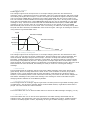
Eobody3 SensorBox User’s Manual USB8/USB8M/USB16/USB16M eowave Table des matières Word n'a pas trouvé d'entrées pour votre table des matières. Dans le document, sélectionnez les mots à inclure dans la table des matières, puis, dans Palette de mise en forme, sous Styles, cliquez sur un style d'en-tête. Répétez l'opération pour chaque en-tête à inclure, puis insérez la table des matières dans le document. Vous pouvez également créer une table des matières en cliquant sur l'option Créer avec mise en forme manuelle, puis tapez les entrées manuellement. Safety instructions • • • • • • • • • • Before using your Eobody3, make sure you have read the following instructions carefully. Do not open or modify the unit or its main adapter when the unit is externally powered. During lightning, unplug the unit; make sure the main adapter (if one) is not plugged. Before cleaning your Eobody3, make sure the main adapter and/or any external elements are disconnected from the unit. Do not try to repair the interface or the components inside of it. Please contact eowave for technical support at [email protected] Do not use your Eobody3 nor store it in dusty areas, damp areas, extreme temperatures, exposed to direct sunlight, areas prone to strong vibrations. If you need to use a main adapter, make sure of the adapter output polarity, voltage and current are correct. Do not insert any objects nor pour any liquid into the unit. Protect the unit against violent shocks. Before using Eobody3 in a foreign country, make sure that your main adapter is compatible with the main supply. Never touch your Eobody3 or its adapter with wet hands when it is plugged in. Never place heavy objects on your Eobody3. If the unit is not to be used for a long period, disconnect the adapter from the main. Congratulations • Congratulations! You now own a new Eobody3 sensorbox, a versatile and plug & play usb-tosensor interface to use sensor directly with your sequencer softwares or with softwares like Cycling’74 Max/MSP/Jitter. Eobody3 sensorbox is unique because it offers an internal powerful processing to shape the out coming sensor signal and get the best results in an intuitive and easy way. No MIDI interface needed, no skills in computer programming required. Eobody3 usb 8 SensorBox is the first module of a very flexible & versatile sensor system whom core is your computer. More modules will be developed in a very near future. Unpacking Your Eobody3 package should include the following items. Make sure everything is in the box. • usb 8 inputs Eobody3 • First steps with your Eobody3 • 1 usb cable Register You may register on www.eowave.com/register.php by entering your Eobody3 serial number. This number is located on a sticker on the back of the unit. Downloads Download and install the editor Download the editor from www.eowave.com/download page. Click on Eobody3 editor. Eobody3 usb sensorbox editor is Mac, MacIntel and PC compatible. Before launching the editor, you need to download the Max5 player (unless you already have a Max5 session). On www.cycling74.com, download Max5 trial. It’s free. Max5 runtime will remain on your computer when the trial is over. Open Max5 runtime before launching the editor. Maxers, note that the editor collective file is also available to avoid having 2 Max apps running on the same computer. When the installation is over, a window pops up with a successful message. EOBODY3 SENSORBOX USER’S MANUAL 3 Powering When using usb or an external powering, you need to set Eobody3 external switch to the right position. USB powering Eobody3 is USB self-powered. Just plug the usb from Eobody3 to your computer usb in. External powering You will need an external powering in the following cases: • Some sensors need more than the usb 3,3V. In this case, you can power the unit externally with a 9 V DC / 500 mA power supply. Connect the 9 V DC / 500 mA power supply into the power plug connector of Eobody3. An internal fuse is activated when not plugged right to avoid major internal damages. How do I know that the sensors I use need an external powering? All 5V sensors need external powering. Eowave 5V sensors are distance sensors. • You are using an Eobody3 with a MIDI output without a computer Eobody3 and my computer To connect your Eobody3 to your computer, connect the USB cable to your computer USB in (or to any USB hub connected to your computer). You do not need any MIDI interface. When connected to your computer, Eobody3 will appear like a new audio device on PC, like Eobody3 MIDI interface on Macs. Two or more Eobody3 can be connected directly to the USB inputs of your computer, but they can also be connected via a USB hub. When several Eobody3 are connected, they will appear like different audio devices with PCs, different Eobody3 MIDI interfaces on Macs. When the units have been named, their given name will appear. My computer does not recognize my Eobody3 On PC, On Mac, MIDI configuration Per default, input 1 is on CC1, input 2 on CC2, etc. So in major cases, your MIDI compatible software will recognize the Eobody3 as a plug and play device. The Global parameter window will appear. Inside the Global Parameters Editor Page, the first three sections define the connection between Eobody3 interface and your computer (select MIDI port; name your eobody; save/load). The fourth section is dedicated to Eobody3 internal memory configuration. • Select Eobody3 MIDI port Eobody3 uses the MIDI protocol to transfer data, which means it is compatible with almost every MIDI software. As it is not using the MIDI standard data transfer rate of 32500 Hz but a much more faster rate, it might cause some problems with some softwares. • your eobody name displays the name of your Eobody3 unit. This function is very useful when you use more than one Eobody3. This given name will appear as the name of the unit. To rename your Eobody3 unit, click on ‘change name’ in the fourth section below. • save to file save configuration inside your computer hard drive. • load to file load configuration from your computer hard drive. Eobody3 internal memory configuration • check current parameters check the internal memory of Eobody3 unit. • save current parameters save current parameters inside the Eobody3 internal memory. Eobody3 has an internal memory to store parameters settings. You may store an entire installation or performance configuration inside one or more Eobody3 and keep it (or them) as back-up units for a future use. • init all parameters initialize to factory settings. • revert to save go back to the configuration saved last. • all off disactivate all parameters. • delay As USB is very fast, some older computer can have problems to receive the high data flow. Increasing the de- lay will reduce the data flow. It will make Eobody3 analyse the analogue input not every scan cycle. • change name rename your Eobody3 unit. The new name will be displayed in the section ‘your Eobody name’. • check name check the name of the Eobody3 unit you are editing when you are editing more than one. • print incoming messages print to screen incoming MIDI messages. Formatting messages to host • type This is one of the most important configuration parameters, since it determines which type of MIDI message the device is going to send in response to variations in a particular analogue input. Eobody3 is capable of generating 5 different messages: • CC: Control number change (Control change) 7 bits CC: Control number change (Control change) 12 bits (the 5 LSB bits are mapped on CC number + 64 • Note: Note on Trigger • PC: Program change • PB: Pitch bend (Variation in pitch) real 12 bits • PB: Pitch bend (Variation in pitch) mapped 14 bits • ATm: Monophonic aftertouch (Channel pressure) • CC Control Change This is the type of message, which will likely be most often used for controlling sound parameters. The value of the analogue signal acts directly upon the value of a MIDI controller, using a MIDI controller Value Change message (control change). The number of the controller can be set by users. If 12 bits resolution is selected, this message will actually send two Control Change messages. The controller specified in the val field will send the 7 least significant bits whilst the controller specified in the “low” field will send the 3 most significant bits, on the same MIDI channel. EOBODY3 SENSORBOX USER’S MANUAL 5 HVVDJH HU • Note on message N-ON trigger hi-low The analogue signal must correspond to an envelope changing with time and which has a XHVLJQDOPXVWFRUUHVSRQGWRDQHQYHORSHFKDQJLQJZLWKWLPHDQGZKLFKKDVD maximum value. 3 parameters need to be specified: note sent, higher threshold, and lower threshDOXHSDUDPHWHUVQHHGWREHVSHFL¿HGQRWHVHQWKLJKHUWKUHVKROGORZHUWKUHVK old. Eobody3 analyses this envelope: once the envelope has reached the higher threshold, a MIDI note on message (NOTE ON) is generated. The velocity associated with the note is fixed to 127. \DQDO\VHVWKLVHQYHORSHRQFHWKHHQYHORSHKDVUHDFKHGWKHKLJKHUWKUHVKROGD The note number contained within the message is adjustable by the user. As long as the envelope QPHVVDJH127(21LVJHQHUDWHG7KHYHORFLW\DVVRFLDWHGZLWKWKHQRWHLV¿[HG stays above a threshold point, named NOTE OFF threshold, the note is maintained (no new MIDI QRWHQXPEHUFRQWDLQHGZLWKLQWKHPHVVDJHLVDGMXVWDEOHE\WKHXVHU$VORQJDV message is sent). When the level falls beneath the NOTE OFF threshold point, a MIDI NOTE OFF HVWD\VDERYHDWKUHVKROGSRLQWQDPHG127(2))WKUHVKROGWKHQRWHLVPDLQ message is sent to turn the note off. To sustain the note for a long period of time, the NOTE QHZ0,',PHVVDJHLVVHQW:KHQWKHOHYHOIDOOVEHQHDWKWKH127(2))WKUHVKROG OFF threshold point must be set on a small value. Conversely, to make the note stop shortly after the peak has been detected, the NOTE OFF value must be higher. This type of message is useful in ',127(2))PHVVDJHLVVHQWWRWXUQWKHQRWHRII7RVXVWDLQWKHQRWHIRUDORQJ PHWKH127( using sensors to generate MIDI notes. ROGSRLQWPXVW :PNUHS VPDOOYDOXH WRPDNHWKH KRUWO\DIWHUWKH 56;, 65 HHQGHWHFWHG [OYLZOVSK 2))YDOXH KHU7KLVW\SH 56;, 6-[OYLZOVSK LVXVHIXOLQ RUVWRJHQHUDWH 56;, 65TLZZHNL 56;, 6--TLZZHNL [ 56;, 65 [ 56;, 6-- [ • Program Change message PC The analogue signal must correspond to an envelope changing with time and which has a maximum value. You will have to specify 3 parameters, Program Change sent, higher threshold, and lower threshold. Eobody3 analyses this envelope: once the envelope has reached the higher threshold, a MIDI Program Change message is generated. The Program Change contained within the message is adjustable by the user. As long as the envelope stays above a threshold, named lower threshold, the Program Change is maintained (no new MIDI message is sent). When the level QDEOHVWKHXVHUWRFRQ¿JXUHWKHQRWHRQDFWLYDWLRQOHYHOIRUWULJJHUPHVVDJHVRUIRU falls beneath the lower threshold, the Eobody3 is ready to receive a new Program Change RQWUROOHUQXPEHUZLWKDORZHUWKUHVKROG message. • Pitch Bend PB This message allows an analogue signal to generate a MIDI message of the pitch change type (pitch bend). Pitch is usually coded over 14 bits. If the 7 bits resolution is chosen, they will be QDEOHVWKHXVHUWRFRQ¿JXUHWKHQRWHRQDFWLYDWLRQOHYHOIRUWULJJHUPHVVDJHVRUIRU mapped on the 7 most significant bits of pitch information controlled by the analogue signal. However, since Eobody3 does 12 bits conversions internally, the whole 12 bits can be mapped to RQWUROOHUQXPEHUZLWKDKLJKHUWKUHVKROG take better advantage of the pitch bend message. This message is used to simulate the pitch changing wheels available on most MIDI keyboards. • Monophonic Aftertouch ATm This message allows an analogue signal to generate a channel pressure type MIDI message (channel aftertouch). This pressure message affects a whole MIDI channel, regardless of what note is played. The user selects the channel number. • message Channel: [1-8] This field enables the user to select a MIDI channel to which the MIDI message will apply (1 to 8). • value val: 0 - 127 This field enables the user to set the fixed parameter of a MIDI message associated with an analogue input. This parameter value may correspond to a MIDI note number, a MIDI controller number or a MIDI program number, depending on the type of MIDI message, which is chosen. DQDORJXHLQSXW7KLVSDUDPHWHUYDOXHPD\FRUUHVSRQGWRD0,',QRWHQXPEHUD0,',FRQWUROOHU QXPEHURUD0,',SURJUDPQXPEHUGHSHQGLQJRQWKHW\SHRI0,',PHVVDJHZKLFKLVFKRVHQ &RQ¿JXUDWLRQPDSIRUDQDORJXHLQSXWV Configuration map for analogue inputs ;`WLVMTLZZHNL 9LZ =HS\L /P3V^ ** *VU[YVS*OHUNL IP[Z **]HS\L ** *VU[YVS*OHUNL IP[Z **]HS\L 5V[L 5V[LVU[YPNNLY IP[Z UV[LU\TILY OPNOLY[OYLZOVSK SV^LY[OYLZOVSK 7* 7YVNYHT*OHUNL IP[Z 7.]HS\L OPNOLY[OYLZOVSK SV^LY[OYLZOVSK 7) 7P[JO)LUK IP[Z 7) 7P[JO)LUK (;T TVUVWOVUPJHM[LY[V\JO IP[Z IP[Z Tutorial T.1.1. How to make a plug & play ribbon controller Subject: This tutorial will show you how to assign a pitch bend to a position sensor to make a ribbon controller. This is a basic configuration that can be used with any MIDI software sequencer. • What is a ribbon controller? • A ribbon controller is a ribbon shaped continuous controller. Some synthesizer from the 70s and 80s had ribbons like the Yamaha CS-80. Ribbons allow playing in a Theremin style, but in an easier way. Nowadays, ribbons (or fingerboard) synthesizers are still made, the Persephone for example. Today, it is possible to make a ribbon controller with a position sensor and use it directly in your software sequencer (with a Eobody3 USB sensor system). Position sensors are also great to simulate faders. • For this example, connect the position sensor in Eobody3 Sensorbox input number 1. • Position sensors are very easy to configure as their range goes continuously from 0-127. It means that in most cases, using the Eobody3 internal process is not necessary. • In the Editor routing window, you will be able to choose the destination (pitch bend or others). • Here is a basic configuration, which should be fine with position, pressure sensors or potentiometers to send 14 bits MIDI to any MIDI compatible software. • Activate input number 1 in the editor (in the processing window, go to state on). • In the routing window, you can choose between Pitch Bend (real 12 bits) and a Pitch Bend (mapped 14 bits). This choice will depend on what on you want to use your ribbon controller with. To use it with a MIDI sequencer, choose a mapped 14 bits Pitch Bend (remember that in MIDI, pitch bend is always 14 bits). If you want to use your ribbon with a software like MAX/MSP, choose a real 12 bits as MAX can receive 12 bits data. • Continuous controllers can be assigned to any sound parameters. In your software sequencer, assign it to the parameter of your choice and start playing! EOBODY3 SENSORBOX USER’S MANUAL 7 Eobody3 sensorbox with 0-5V inputs (USB8/USB8M/USB16/USB16M) (RERG\86%6HQVRU%R[7XWRULDOV7 Inputs are Neutrik TRS double jacks 6’35. TRS format has been chosen because this is a world (RERG\86%6HQVRU%R[/LYH6HQVRU&RQWUR wide used format that can be found anywhere and easily repaired. On sensors inputs, TRS jack tips are powered with 5V. 0-5V inputs have a 1 pole low-pass filter and a buffer to accept different signals and filter data before the A/D conversion. 7XWRULDO Plug&play mode 0RGXODWHDSDUDPHWHUZLWKDFRQWLQXRXVFRQWUROOHU In most cases, the editor is not required. • Connect a sensor to your Eobody3, input1 ZLWK$EOHWRQ/LYH • Connect your Eobody3 to your computer. • Open your MIDI compatible software • Input1 is on CC1 per default, input2 on CC2… • Modulate your MIDI CC1 parameter with your sensor. 1RWHWKDWIRUWKLVFRQILJXUDWLRQ\RXGRQRWQHHG(RERG\86%6HQVRU%R[(GLWRU 7RFRQQHFW\RXU(RERG\86%6HQVRU%R[WR\RXUFRPSXWHUSOHDVHUHIHUWR7XWRULDO7 When do I need the editor then? )LUVW6WHSVZLWK\RXU(RERG\ With the editor, you will be able to: :KDWNLQGRIFRQWLQXRXVFRQWUROOHUFDQ,XVH"&RQWLQXRXVFRQWUROOHUVDUHSRWHQWLRPHWHUV • Change de MIDI channel affectation ULEERQVSUHVVXUHVHQVRUVDOOVHQVRUVWKDWKDYHDUDQJHIURPWR • Process the in coming signal with pre-processing tools to adapt it to your special use. • Make settings and record them in the non-volatile memory to use the Eobody3 without computer (thru the MIDI output). Tutorial 1.2. Modulate a parameter with a continuous controller with Ableton Live 6 VWHS &RQILJXUH\RXU(RERG\86%6HQVRU%R[LQ$EOHWRQ/LYH • Note that for this configuration, you do not need Eobody3 Sensorbox Editor. • Connect your Eobody3 Sensorbox to your ,Q/LYHLQWKH2SWLRQPHQXJRLQWKH3UHIHUHQFHVZLQGRZ computer; please refer to Tutorial T. 0.1. ,QWKH0,',V\QFILOHDFWLYDWH³UHPRWHRQ´DVVKRZQRQWKHSLFWXUH • What kind of continuous controller can I use? Continuous controllers are potentiometers, ribbons, pressure sensors, all sensors that have a range from 0 to 127. • Configure your Eobody3 SensorBox in Ableton Live6 • In Live, in the Option menu, go in the 1RZJREDFNWR/LYHPDLQZLQGRZ7KH0,',VWDWXV/('LQWKHXSSHU Preferences window. In the MIDI sync FRUQHUVKRXOGEHEOLQNLQJZKHQ\RXXVHDVHQVRU file, activate “remote on” as shown on the picture. • Now, go back to Live main window. &OLFNRQ0,',WRODXQFK0,',DXWRPDWLRQSDUDPHWHUV • Click on MIDI to launch MIDI automation parameters VWHS &KRRVHWKHSDUDPHWHU\RXZDQWWRPRGXODWH :LWK\RXUPRXVHFOLFNRQWKHSDUDPHWHU\RXZDQWWRPRGXODWHZLWKD VHQVRU7KHVHOHFWHGSDUDPHWHUZLOOWXUQSXUSOH$XWRILOWHUIUHTXHQFHLQ H[DPSOH6OLJKWO\PRYH\RXUVHQVRU VWHS &KRRVHWKHSDUDPHWHU\RXZDQWWRPRGXODWH • Choose the parameter you want to :LWK\RXUPRXVHFOLFNRQWKHSDUDPHWHU\RXZDQWWRPRGXODWHZLWKD modulate VHQVRU7KHVHOHFWHGSDUDPHWHUZLOOWXUQSXUSOH$XWRILOWHUIUHTXHQFHLQ • With your mouse, click on the parameter H[DPSOH6OLJKWO\PRYH\RXUVHQVRU you want to modulate with a sensor. The selected parameter will turn purple. Auto filter frequency in this example. Slightly move your sensor. • In the MIDI mapping window, you can now read CC1 mapped auto-filter frequency. Quit MIDI automation by ,QWKH0,',PDSSLQJZLQGRZ\RXFDQQRZUHDG&&PDSSHGDXWRILOWH clicking the MIDI button. IUHTXHQF\4XLW0,',DXWRPDWLRQE\FOLFNLQJWKH0,',EXWWRQ HRZDYHF$OO5LJKWV5HVHUYHGLQIR#HRZDYHFRPZZZHRZDYHFRP Pre-processing tools for sensors Pre-processing is the process of translating electric variations coming from a sensor into comprehensive and exploitable data. Data from sensors can be processed using the pre-processing tools to get the best exploitable signal for a specific use. The 32 bit IC allows to have different processes according to the type of data, standard sensors (continuous controller), triggers (peak detection), simple logic or more complex analysis like algorithms for certain sensors like gyroscopes for example. Figure: Signal path Signal from analogue inputs goes thru analogue filters and buffers before A/D conversion. Then, pre-processing tools are available to reshape the signal: invert, zoom, offset, digital filter, noise gate, wave shaper. Pre-mapping settings per sensors are included. In the editor, the Parameters window enables to adjust internal processing parameters for each input (1 to 8 – 9 to 16). Refer to the description of each parameter for use. To increase or decrease parameter values, click on the case you want to edit and slightly move up or down your mouse. Note that all setting parameters changes are made in real time. To save a configuration, click on «save current parameters». • Status on/off The status field indicates whether the signal on an analogue input should be converted into a digital message or not. This field may be set to ON or OFF. If the field is set to OFF, the input is said to be inactive and no message relating to that input will be generated, even if a signal does physically enter the device. If the field is switched back to ON, the input is active and its associated message will be sent each time the signal connected to that input varies in level. Note: The smaller the number of active inputs is, the less data will be transmitted avoiding processor computation. EOBODY3 SENSORBOX USER’S MANUAL 9 DQDORJXH]RRP ³DQDORJXH]RRP´FRQWUROVWKHLQWHUQDO3*$3URJUDPPDEOH*DLQ$PSOL¿HU JLYHVDIDFWRURIDPSOL¿FDWLRQ7KHXVHRIDQDORJXH]RRPLQJZLOONHHSWKHIXOO ELWGHSWKRIYDOXHV GLJLWDO]RRPDQGRIIVHW • digital zoom and offset GLJLWDO]RRPPD[PLGORZRIIRQ digital zoom: max/mid/low/off on 7 offset: -127 to +127 RIIVHWWR 40+0 KH[H IP[Z +PNP[HS]HS\L IP[Z 40+0JVU]LYZPVU %VHQVRULQWHUIDFH3DUDPHWHUVZLQGRZ aVVTZL[[PUN $ YLHSZLUZVYYHUNL 6MMZL[ :DQWWRVWD\LQWKHELW0,',ZRUOG 7KRVHWZRSDUDPHWHUVGLJLWDO]RRPDQGRIIVHW VSHFLI\KRZWKHUHDOUDQJHRIDQDQDORJXHLQSXW FDQEHPDSSHGRQDELW0,',YDOXH$VDPDW To be compatible with the 7-bit MIDI world... WHURIIDFWDVHQVRUGRHVQRWQHFHVVDULO\KDYH Those two parameters (digital zoom and offset) DUDQJHHTXDOWRWKHUHIHUHQFHYROWDJHRIWKH specify how the real range of an analogue input $QDORJXHWR'LJLWDO&RQYHUWHU$FXVWRPVFDOHG can be mapped on a 7-bit MIDI value. As a matter of fact, a sensor does not necessarily ]RRPKDVEHHQLPSOHPHQWHGRQWKHGLJLWDOYDOXH have a range equal to the reference voltage of WRWDNHDGYDQWDJHRIWKHELWUHVROXWLRQRIWKH the Analogue to Digital Converter. A custom $'FRQYHUWHU)LUVWWKHYROWDJHUHIHUHQFHKDVWR scaled zoom has been implemented on the EHVHWWRWKHODUJHVWUDQJHDPRQJWKHVHQVRUV digital value to take advantage of the 12-bit FRQQHFWHGWRWKHXQLW7KHQWKHXVHUFDQVHOHFW resolution of the A/D converter. First, the voltage reference has to be set to the largest WKHVHQVRU¶VUDQJHZLWKLQWKHELWVG\QDPLF range among the sensors connected to the unit. E\VSHFLI\LQJDZLQGRZVL]HDQGDQRIIVHW7KH Then, the user can select the sensor’s range VHOHFWHGUDQJHFDQWKHQEHFRQYHUWHGLQWRELWV within the 12 bits dynamic by specifying a 0,',GDWDZLWKRXWJUHDWO\LQFUHDVLQJWKHTXDQWL¿ window size and an offset. The selected range FDWLRQVWHSDVVKRZQLQWKHLOOXVWUDWLRQ can then be converted into 7 bits MIDI data without greatly increasing the quantification step, as shown in the illustration. 7KHGLJLWDO]RRPRIIVHWSDUDPHWHUVPD\EH QGEHFRPHV7KLVZD\\RXPD\LQYHUVHWKHFXUVHRIDVHQVRU The digital zoom & offset parameters may be YHU\XVHIXOWRPRGXODWHD¿OWHURQDFHUWDLQSDUW very useful to modulate a filter on a certain part QSHGDOIRUH[DPSOH\RX¶OOEHDEOHWRLQYHUVHLWVFXUVH RIWKHDPSOLWXGH of the amplitude. • inverse 127 becomes 0 and 0 becomes 127. This way you may inverse the curse of a sensor. With an expression pedal, for example, you’ll be able to inverse its curse. WHUWKDWVPRRWKHVWKHVLJQDOIRUXQVWDEOHVHQVRUV • filter 0-64 32 bits low-pass filter that smoothes the signal - for unstable sensors. • gate noise gate:12 values [0-11] HV>@ KROGUHGXFHV :LUZVY 5VPZLIHUK HVLJQDO,IWKH :LUZVYZPNUHS RYHVLQVLGH :HTWSLK]HS\L RLVHJDWHQR UVPZL :HTWSLK]HS\L HQW7KLV¿HOG 40+0TLZZHNL RVHWWKHZLGWK JHUDQJHZLOO JDLQVWVWURQJ HWKHYDOXHV UHOHYDQW ORJXHVLJQDO RUUHVSRQGVWR [ LEOHYDOXHVLH WRFKDQJHDW DERYHRUXQGHULWVFXUUHQWSRVLWLRQWREHGHWHFWHGDVFKDQJLQJ$ UUHVSRQGVWRELWVXVHIXOOIRUVZLWFKHVRUDOORQRIIVHQVRUV A noise gate threshold reduces the bit depth of the signal. If the analogue signal moves inside the range of the noise gate, no message will be sent. This field enables the user to set the width of the range. A large range will be very effective against strong noise but will make the values less sensitive to a relevant change of the analogue signal. A threshold of 5 corresponds to 127 different possible values (i.e.: the analogue has to change at least of 32 (from 4095 above or under its current position to be detected as changing). A threshold of 11 corresponds to 2 bits, useful for switches or all on/off sensors. • curve Eobody3 has a new pre-processing tool called curve (for response curve). This wave shaping new feature allows changing the curve of a signal. For example, the linear response of a volume pedal can be changed to a logarithmic or exponential response. EOBODY3 SENSORBOX USER’S MANUAL 11 Sensors pre-mapping All Eowave sensors are ready to use with Eobody3 Sensorboxes. They have been designed to get the best signal response with additionnal filters and amplifying circuitry. They are calibrated for maximum bandwidth. Many are plug&play and do not need extra processing. The following table is for Eowave sensors only. More information on each sensor can be found in the sensors datasheet available on www.eowave.com Sensor type Number of inputs Continuous/ on/off Active /passive Integratedad ditionnal circuitry yes Editor parameters setting active Need ext. power no 2D GForce 2 0-127 3D GForce 3 0-127 active no yes IR 1 Plug&play 0-127 active yes yes - the output signal can be amplified by setting the analogue zoom on 1 - To reduce IR noise, filter the signal in the editor by setting a high filter value. Light movement 1 0-127 passive no yes Plug&play 1 On/off passive no yes Plug&play detection 1 On/off active yes A gate value of 11 will reduce noise to avoid uncontrolled triggering. flexion 1 0-127 passive no Plug&play. Sensitivity can be set with the external trimmer. footswitch 1 On/off passive no Yes External trimmer yes joystick Expression pedal 2 1 0-127 0-127 passive passive no no yes no position 1 0-127 passive no yes - Plug&play - Plug&play - Note that you can use the inverse feature. - the linear response of a pedal can be changed to a logarithmic or exponential response with the curve parameter. Plug&play pressure 1 0-127 passive no yes Plug&play potentiometer 1 0-127 passive no no Plug&play Shock piezzo 1 On/off passive no Yes amplifier switch 1 On/off passive no no Use a sensorbox with trigger inputs, which are sensitive to the velocity. A gate value of 11 will reduce noise to avoid uncontrolled triggering. Plug&play A gate value of 11 reduce will noise to avoid uncontrolled triggering. temperature 1 0-127 passive no no Plug&play ultrasonic 1 0-127 active yes yes Note that when using more than one, they need to be synchronized. (Only with digital I/O). Gyroscope 2 axis 2 0-127 passive yes Gyroscope 5 axis 5 0-127 passive yes sonometer 1 0-127 passive Plug&play Plug&play A gate value of 11 will reduce noise to avoid uncontrolled triggering. ,90DNLQJP\RZQVHQVRUV Making my own sensors ,90DNLQJP\RZQVHQVRUV ,90DNLQJP\RZQVHQVRUV HRERG\VXSSRUWVPDQ\NLQGRIVHQVRUV0RVWFRPPRQVHQVRUVDUHVZLWFKHVDQGSRWHQWLRPHWHUV Eobody3 supports many kinds of sensors. Most common sensors are switches and potentiometers, EXWWKHUHDUHPDQ\RWKHUNLQGVRIVHQVRUV but there are many other kinds of sensors. HRERG\VXSSRUWVPDQ\NLQGRIVHQVRUV0RVWFRPPRQVHQVRUVDUHVZLWFKHVDQGSRWHQWLRPHWHUV HRERG\VXSSRUWVPDQ\NLQGRIVHQVRUV0RVWFRPPRQVHQVRUVDUHVZLWFKHVDQGSRWHQWLRPHWHUV 0DNLQJP\RZQVHQVRUVZLWFK • Making my own sensor switch EXWWKHUHDUHPDQ\RWKHUNLQGVRIVHQVRUV EXWWKHUHDUHPDQ\RWKHUNLQGVRIVHQVRUV :^P[JO 0DNLQJP\RZQVHQVRUVZLWFK 0DNLQJP\RZQVHQVRUVZLWFK 6HQVRUVQHHGDPLQLPXPRIWZRFDEOHV JURXQGDQGVLJQDO:KHQ9LVFRQQHFWHG WRWKHVLJQDOZKHQXVLQJVZLWFKHVIRUH[ :^P[JO 6HQVRUVQHHGDPLQLPXPRIWZRFDEOHV :^P[JO 6HQVRUVQHHGDPLQLPXPRIWZRFDEOHV DPSOHLWPD\FUHDWHDQDQWHQQDHIIHFWJHQ JURXQGDQGVLJQDO:KHQ9LVFRQQHFWHG JURXQGDQGVLJQDO:KHQ9LVFRQQHFWHG HUDWLQJXQGHVLUDEOHGGLVWRUVLRQ7KLVLVWKH WRWKHVLJQDOZKHQXVLQJVZLWFKHVIRUH[ 2VOT WRWKHVLJQDOZKHQXVLQJVZLWFKHVIRUH[ [VH]VPKHU[LUUHLMMLJ[ UHDVRQZK\WKHVLJQDOPXVWEHFRQQHFWHGWR DPSOHLWPD\FUHDWHDQDQWHQQDHIIHFWJHQ NYV\UK DPSOHLWPD\FUHDWHDQDQWHQQDHIIHFWJHQ WKHJURXQG ^OLU[OLZ^P[JOPZVMM HUDWLQJXQGHVLUDEOHGGLVWRUVLRQ7KLVLVWKH HUDWLQJXQGHVLUDEOHGGLVWRUVLRQ7KLVLVWKH 2VOT 2VOT UHDVRQZK\WKHVLJQDOPXVWEHFRQQHFWHGWR [VH]VPKHU[LUUHLMMLJ[ = :PNUHS [VH]VPKHU[LUUHLMMLJ[ UHDVRQZK\WKHVLJQDOPXVWEHFRQQHFWHGWR NYV\UK NYV\UK ^OLU[OLZ^P[JOPZVMM WKHJURXQG WKHJURXQG ^OLU[OLZ^P[JOPZVMM (Connecting the ground avoids antenna effect when the switch is off) = 0DNLQJP\RZQVHQVRUSRWHQWLRPHWHU = :PNUHS :PNUHS Sensors need a minimum of two cables: ground and signal. When 5 V is connected to the signal when using switches for ex- ample - it may create an antenna effect generating undesirable distortion. This is the reason why the signal must be connected to the ground. 0DNLQJP\RZQVHQVRUSRWHQWLRPHWHU 7V[LU[PVTL[LY 0DNLQJP\RZQVHQVRUSRWHQWLRPHWHU 7RXVHDVWDQGDUGSRWHQWLRPHWHUZLWKHRERG\FRQQHFWERWK RXWSXWVRIWKHSRWHQWLRPHWHUUHVLVWRUWRWKHJURXQGDQG9 = • Making my own sensor NYV\UK potentiometer 7V[LU[PVTL[LY 7V[LU[PVTL[LY = = NYV\UK NYV\UK :PNUHS &RQQHFWWKHYDULDEOHRXWSXWRIWKHSRWHQWLRPHWHUWRWKHVLJQDO 7RXVHDVWDQGDUGSRWHQWLRPHWHUZLWKHRERG\FRQQHFWERWK 7RXVHDVWDQGDUGSRWHQWLRPHWHUZLWKHRERG\FRQQHFWERWK LQSXW RXWSXWVRIWKHSRWHQWLRPHWHUUHVLVWRUWRWKHJURXQGDQG9 RXWSXWVRIWKHSRWHQWLRPHWHUUHVLVWRUWRWKHJURXQGDQG9 &RQQHFWWKHYDULDEOHRXWSXWRIWKHSRWHQWLRPHWHUWRWKHVLJQDO &RQQHFWWKHYDULDEOHRXWSXWRIWKHSRWHQWLRPHWHUWRWKHVLJQDO LQSXW LQSXW :PNUHS 0DNLQJP\RZQVHQVRUZLWKRWKHUNLQGVRIVHQVRUV :PNUHS To use a standard potentiometer with Eobody3, connect both outputs of the potentiometer resistor 0DNLQJP\RZQVHQVRUZLWKRWKHUNLQGVRIVHQVRUV to the ground and 5 V. Connect the variable output of the potentiometer to the signal input. 0DNLQJP\RZQVHQVRUZLWKRWKHUNLQGVRIVHQVRUV &RPLQJIURP(RERG\RUH[WHUQDOSRZHUVXSSO\DQ\RWKHU • Making my own sensor with other kinds of sensors YROWDJHKDVWRFRPHIURPDQH[WHUQDOSRZHUVXSSO\ =VY = :LUZVY &RPLQJIURP(RERG\RUH[WHUQDOSRZHUVXSSO\DQ\RWKHU NYV\UK &RPLQJIURP(RERG\RUH[WHUQDOSRZHUVXSSO\DQ\RWKHU 6RPHVHQVRUVOLNHGLVWDQFHVHQVRUVQHHGDQH[WUDSRZHU YROWDJHKDVWRFRPHIURPDQH[WHUQDOSRZHUVXSSO\ =VY = YROWDJHKDVWRFRPHIURPDQH[WHUQDOSRZHUVXSSO\ =VY = VXSSO\(RERG\GHOLYHUV9DQG9WRSRZHUWKHVH :LUZVY :LUZVY VHQVRUVXSWRP$:KHQWKHWRWDOFRQVXPSWLRQIURP NYV\UK NYV\UK 6RPHVHQVRUVOLNHGLVWDQFHVHQVRUVQHHGDQH[WUDSRZHU 6RPHVHQVRUVOLNHGLVWDQFHVHQVRUVQHHGDQH[WUDSRZHU NYV\UK NYV\UK NYV\UK :PNUHS DOOWKHVHQVRUVSOXJJHGWR(RERG\LVKLJKHUWKDQP$ VXSSO\(RERG\GHOLYHUV9DQG9WRSRZHUWKHVH VXSSO\(RERG\GHOLYHUV9DQG9WRSRZHUWKHVH DQDGGLWLRQDOH[WHUQDOSRZHUVXSSO\LVQHFHVVDU\ VHQVRUVXSWRP$:KHQWKHWRWDOFRQVXPSWLRQIURP VHQVRUVXSWRP$:KHQWKHWRWDOFRQVXPSWLRQIURP DOOWKHVHQVRUVSOXJJHGWR(RERG\LVKLJKHUWKDQP$ DOOWKHVHQVRUVSOXJJHGWR(RERG\LVKLJKHUWKDQP$ DQDGGLWLRQDOH[WHUQDOSRZHUVXSSO\LVQHFHVVDU\ DQDGGLWLRQDOH[WHUQDOSRZHUVXSSO\LVQHFHVVDU\ :PNUHS :PNUHS Some sensors like distance sensors need an extra power supply. Eobody3 delivers +5V and +9V to power these sensors up to 250 mA. When the total consumption from all the sensors plugged to Eobody3 is higher than 250 mA, an additional external power supply is necessary. EOBODY3 SENSORBOX USER’S MANUAL 13 How to connect standard expression pedals or footswitches to my Eobody3 7XWRULDO+RZWRFRQQHFWVWDQGDUWH[SUHVVLRQSHGDOV 7XWRULDO+RZWRFRQQHFWVWDQGDUWH[SUHVVLRQSHGDOV There are mainly two wiring norms for pedals on the market: the Yamaha norm and the Roland RUIRRWZLWFKHVWRP\(RERG\ RUIRRWZLWFKHVWRP\(RERG\ norm. With your Eobody3, you may use directly all expression pedals or footswitches at the Yamaha norm. To use pedals and footswitches, which respond to the Roland norm, you need to 7KHUHDUHPDLQO\WZRZLULQJQRUPVIRUSHGDOVRQWKHPDUNHWWKH<DPDKDQRUPDQGWKH5RODQGQRUP:LWK\RXU 7KHUHDUHPDLQO\WZRZLULQJQRUPVIRUSHGDOVRQWKHPDUNHWWKH<DPDKDQRUPDQGWKH5RODQGQRUP:LWK\RXU modify your pedals or build an adapter. Before you decide to modify your pedal, be aware that this (RERG\\RXPD\XVHGLUHFWO\DOOH[SUHVVLRQSHGDOVRUIRRWVZLWFKHVDWWKH<DPDKDQRUP7RXVHSHGDOVDQG (RERG\\RXPD\XVHGLUHFWO\DOOH[SUHVVLRQSHGDOVRUIRRWVZLWFKHVDWWKH<DPDKDQRUP7RXVHSHGDOVDQG is a hardware modification and that, once modified, your pedal won’t work with other Roland type IRRWVZLWFKHVZKLFKUHVSRQGWRWKH5RODQGQRUP\RXQHHGWRPRGLI\\RXUSHGDOVRUEXLOGDQDGDSWHU%HIRU\RXGHFLGHWR IRRWVZLWFKHVZKLFKUHVSRQGWRWKH5RODQGQRUP\RXQHHGWRPRGLI\\RXUSHGDOVRUEXLOGDQDGDSWHU%HIRU\RXGHFLGHWR devices anymore. Eowave declines all responsibility for your modification. If you’re not sure that PRGLI\\RXUSHGDOEHDZDUHWKDWWKLVLVDKDUGZDUHPRGLILFDWLRQDQGWKDWRQFHPRGLILHG\RXUSHGDOZRQW¶WZRUNZLWK PRGLI\\RXUSHGDOEHDZDUHWKDWWKLVLVDKDUGZDUHPRGLILFDWLRQDQGWKDWRQFHPRGLILHG\RXUSHGDOZRQW¶WZRUNZLWK RWKHU5RODQGW\SHGHYLFHVDQ\PRUH(RZDYHGHFOLQHVDOOUHVSRQVDELOLW\IRU\RXUPRGLILFDWLRQ,I\RX¶UHQRWVXUHWKDW\RX you have RWKHU5RODQGW\SHGHYLFHVDQ\PRUH(RZDYHGHFOLQHVDOOUHVSRQVDELOLW\IRU\RXUPRGLILFDWLRQ,I\RX¶UHQRWVXUHWKDW\RX the skills for doing this modification by yourselves, ask a professional. \RXKDYHWKHVNLOOVIRUGRLQJWKLVPRGLILFDWLRQE\\RXUVHOYHVDVNDSURIHVVLRQDO \RXKDYHWKHVNLOOVIRUGRLQJWKLVPRGLILFDWLRQE\\RXUVHOYHVDVNDSURIHVVLRQDO 1 • Roland norm vs. Yamaha norm 7XWRULDO+RZWRFRQQHFWVWDQGDUWH[SUHVVLRQSHGDOV 5RODQGQRUPYV<DPDKDQRUP 5RODQGQRUPYV<DPDKDQRUP Roland norm expression pedal connection Eobody connection RUIRRWZLWFKHVWRP\(RERG\ 5RODQGQRUPH[SUHVVLRQSHGDOFRQQHFWLRQ 5RODQGQRUPH[SUHVVLRQSHGDOFRQQHFWLRQ(RERG\FRQQHFWLRQ (RERG\FRQQHFWLRQ 7KHUHDUHPDLQO\WZRZLULQJQRUPVIRUSHGDOVRQWKHPDUNHWWKH<DPDKDQRUPDQGWKH5RODQGQRUP:LWK\RXU Y Y Y Y (RERG\\RXPD\XVHGLUHFWO\DOOH[SUHVVLRQSHGDOVRUIRRWVZLWFKHVDWWKH<DPDKDQRUP7RXVHSHGDOVDQG IRRWVZLWFKHVZKLFKUHVSRQGWRWKH5RODQGQRUP\RXQHHGWRPRGLI\\RXUSHGDOVRUEXLOGDQDGDSWHU%HIRU\RXGHFLGHWR PRGLI\\RXUSHGDOEHDZDUHWKDWWKLVLVDKDUGZDUHPRGLILFDWLRQDQGWKDWRQFHPRGLILHG\RXUSHGDOZRQW¶WZRUNZLWK RWKHU5RODQGW\SHGHYLFHVDQ\PRUH(RZDYHGHFOLQHVDOOUHVSRQVDELOLW\IRU\RXUPRGLILFDWLRQ,I\RX¶UHQRWVXUHWKDW\RX JURXQG JURXQG JURXQG JURXQG \RXKDYHWKHVNLOOVIRUGRLQJWKLVPRGLILFDWLRQE\\RXUVHOYHVDVNDSURIHVVLRQDO LQSXWVLJQDO LQSXWVLJQDO LQSXWVLJQDO 7XWRULDO+RZWRFRQQHFWVWDQGDUWH[SUHVVLRQSHGDOV LQSXWVLJQDO 5RODQGQRUPYV<DPDKDQRUP RUIRRWZLWFKHVWRP\(RERG\ 7REXLOGDQDGDSWHU 7RPRGLI\\RXUSHGDO 7REXLOGDQDGDSWHU6ROGHU 7RPRGLI\\RXUSHGDO 6ROGHU • To modify your pedal *URXQGWRJURXQG 5RODQGQRUPH[SUHVVLRQSHGDOFRQQHFWLRQ (RERG\FRQQHFWLRQ <RXQHHGRQHZLUHVFDEOH 7KHUHDUHPDLQO\WZRZLULQJQRUPVIRUSHGDOVRQWKHPDUNHWWKH<DPDKDQRUPDQGWKH5RODQGQRUP:LWK\RXU *URXQGWRJURXQG 2SHQWKHMDFN <RXQHHGRQHZLUHVFDEOH 2SHQWKHMDFN 7LSWRULQJ (RERG\\RXPD\XVHGLUHFWO\DOOH[SUHVVLRQSHGDOVRUIRRWVZLWFKHVDWWKH<DPDKDQRUP7RXVHSHGDOVDQG RQHVWHUHRMDFNFRQQHFWRU 7LSWRULQJ ,QYHUWWLSULQJFDEOHV RQHVWHUHRMDFNFRQQHFWRU Open the ,QYHUWWLSULQJFDEOHV jackIRRWVZLWFKHVZKLFKUHVSRQGWRWKH5RODQGQRUP\RXQHHGWRPRGLI\\RXUSHGDOVRUEXLOGDQDGDSWHU%HIRU\RXGHFLGHWR 5LQJWRWLS RQHVWHUHRMDFNIHPDOHFRQQHFWRU Y Y /HDYHWKHJURXQGXQFKDQJHG 5LQJWRWLS RQHVWHUHRMDFNIHPDOHFRQQHFWRU PRGLI\\RXUSHGDOEHDZDUHWKDWWKLVLVDKDUGZDUHPRGLILFDWLRQDQGWKDWRQFHPRGLILHG\RXUSHGDOZRQW¶WZRUNZLWK /HDYHWKHJURXQGXQFKDQJHG Invert tip & ring cables RWKHU5RODQGW\SHGHYLFHVDQ\PRUH(RZDYHGHFOLQHVDOOUHVSRQVDELOLW\IRU\RXUPRGLILFDWLRQ,I\RX¶UHQRWVXUHWKDW\RX Leave the ground unchanged \RXKDYHWKHVNLOOVIRUGRLQJWKLVPRGLILFDWLRQE\\RXUVHOYHVDVNDSURIHVVLRQDO .5HVLVWRU 6WDQGDUGZLUHIRRWVZLWFK .5HVLVWRU an 6WDQGDUGZLUHIRRWVZLWFK • To build JURXQG JURXQG adapter 5RODQGQRUPYV<DPDKDQRUP WKHORQJSLQLVRIWHQULQJ LQSXWVLJQDO LQSXWVLJQDO WKHORQJSLQLVRIWHQULQJ YouPRVWFRPPRQIRRWVZLWFK need: 5RODQGQRUPH[SUHVVLRQSHGDOFRQQHFWLRQ (RERG\FRQQHFWLRQ PRVWFRPPRQIRRWVZLWFK one 3 wires cable, 7REXLOGDQDGDSWHU WKHVKRUWSLQLVRIWHQWLS 7RPRGLI\\RXUSHGDO 6ROGHU Y one stereo jack connector, Y WKHVKRUWSLQLVRIWHQWLS <RXPD\FKHFNWKHULQJWLSZLWKD *URXQGWRJURXQG one stereo jack female connector <RXQHHGRQHZLUHVFDEOH 2SHQWKHMDFN <RXPD\FKHFNWKHULQJWLSZLWKD 7LSWRULQJ RQHVWHUHRMDFNFRQQHFWRU Solder: Ground SLQ to ground, Tip to ring, Ring to tip PXOWLPHWHULI\RX·UHQRWVXUH ,QYHUWWLSULQJFDEOHV PXOWLPHWHULI\RX·UHQRWVXUH SLQ 5LQJWRWLS SLQ RQHVWHUHRMDFNIHPDOHFRQQHFWRU /HDYHWKHJURXQGXQFKDQJHG SLQ JURXQG JURXQG • Standard wire footswitch • To modify your footswitch LQSXWVLJQDO LQSXWVLJQDO 7RPRGLI\\RXUVZLWFK 7REXLOGDQDGDSWHU 7RPRGLI\\RXUVZLWFK 7REXLOGDQDGDSWHU FXWWKHPRQRMDFN <RXQHHGRQHZLUHFDEOH 6WDQGDUGZLUHIRRWVZLWFK You may check the ring/tip with a multimeter if Cut.5HVLVWRU the mono jack FXWWKHPRQRMDFN UHSODFHLWE\DVWHUHRMDFN <RXQHHGRQHZLUHFDEOH 7REXLOGDQDGDSWHU 7RPRGLI\\RXUSHGDORQHVWHUHRMDFNFRQQHFWRU Replace it by a stereo jack 6ROGHU you’re not sure. UHSODFHLWE\DVWHUHRMDFN FRQQHFWRQHZLUHWR9SLQWLS RQHVWHUHRMDFNFRQQHFWRU RQHVWHUHRRUPRQRMDFNIHPDOHFRQQHFWRU WKHORQJSLQLVRIWHQULQJ <RXQHHGRQHZLUHVFDEOH Connect one wire to +5 V pin*URXQGWRJURXQG (tip) FRQQHFWRQHZLUHWR9SLQWLS FRQQHFWRQHZLUHWRWKHVLJQDOULQJ 2SHQWKHMDFN RQHVWHUHRRUPRQRMDFNIHPDOHFRQQHFWRU PRVWFRPPRQIRRWVZLWFK 7LSWRULQJ RQHVWHUHRMDFNFRQQHFWRU Connect one wire to the signal (ring) FRQQHFWRQH.UHVLVWRUEHWZHHQ FRQQHFWRQHZLUHWRWKHVLJQDOULQJ ,QYHUWWLSULQJFDEOHV 6ROGHU 5LQJWRWLS RQHVWHUHRMDFNIHPDOHFRQQHFWRU JURXQGDQGVLJQDOULQJ /HDYHWKHJURXQGXQFKDQJHG FRQQHFWRQH.UHVLVWRUEHWZHHQ JURXQGIURPIHPDOHWRULQJRIPDOHFRQQHFWRU 6ROGHU Connect one 3K resistor between ground and WKHVKRUWSLQLVRIWHQWLS WLSWRWLS JURXQGDQGVLJQDOULQJ JURXQGIURPIHPDOHWRULQJRIPDOHFRQQHFWRU signal (ring) .UHVLVWRUEHWZHHQULQJJURXQGIURPPDOHFRQQHFWRU <RXPD\FKHFNWKHULQJWLSZLWKD WLSWRWLS PXOWLPHWHULI\RX·UHQRWVXUH .5HVLVWRU 6WDQGDUGZLUHIRRWVZLWFK .UHVLVWRUEHWZHHQULQJJURXQGIURPPDOHFRQQHFWRU SLQ SLQ WKHORQJSLQLVRIWHQULQJ HRZDYHF$OO5LJKWV5HVHUYHGLQIR#HRZDYHFRPZZZHRZDYHFRP PRVWFRPPRQIRRWVZLWFK HRZDYHF$OO5LJKWV5HVHUYHGLQIR#HRZDYHFRPZZZHRZDYHFRP 7RPRGLI\\RXUVZLWFK 7REXLOGDQDGDSWHU FXWWKHPRQRMDFN UHSODFHLWE\DVWHUHRMDFN FRQQHFWRQHZLUHWR9SLQWLS SLQ FRQQHFWRQHZLUHWRWKHVLJQDOULQJ FRQQHFWRQH.UHVLVWRUEHWZHHQ JURXQGDQGVLJQDOULQJ <RXQHHGRQHZLUHFDEOH WKHVKRUWSLQLVRIWHQWLS RQHVWHUHRMDFNFRQQHFWRU <RXPD\FKHFNWKHULQJWLSZLWKD RQHVWHUHRRUPRQRMDFNIHPDOHFRQQHFWRU PXOWLPHWHULI\RX·UHQRWVXUH SLQ • To build an adapter 6ROGHU JURXQGIURPIHPDOHWRULQJRIPDOHFRQQHFWRU 7RPRGLI\\RXUVZLWFK 7REXLOGDQDGDSWHU WLSWRWLS You need: FXWWKHPRQRMDFN <RXQHHGRQHZLUHFDEOH .UHVLVWRUEHWZHHQULQJJURXQGIURPPDOHFRQQHFWRU one 3 wire cable, UHSODFHLWE\DVWHUHRMDFN RQHVWHUHRMDFNFRQQHFWRU one stereo jack connector, FRQQHFWRQHZLUHWR9SLQWLS RQHVWHUHRRUPRQRMDFNIHPDOHFRQQHFWRU one stereo or mono jack female connector FRQQHFWRQHZLUHWRWKHVLJQDOULQJ FRQQHFWRQH.UHVLVWRUEHWZHHQ Solder ground from female to ring of male 6ROGHU HRZDYHF$OO5LJKWV5HVHUYHGLQIR#HRZDYHFRPZZZHRZDYHFRP JURXQGDQGVLJQDOULQJ JURXQGIURPIHPDOHWRULQJRIPDOHFRQQHFWRU connector, tip to tip, 3K resistor between WLSWRWLS ring/ground from male connector. .UHVLVWRUEHWZHHQULQJJURXQGIURPPDOHFRQQHFWRU HRZDYHF$OO5LJKWV5HVHUYHGLQIR#HRZDYHFRPZZZHRZDYHFRP Amplification $PSOL¿FDWLRQ Some sensors have a weak signal out and need amplifying. To avoid undesirable noises, the amplifier should be placed as close as possible from the sensor. 6RPHVHQVRUVKDYHDZHDNVLJQDORXWDQGQHHGDPSOLI\LQJ7RDYRLGXQGHVLUDEOHQRLVHVWKH $PSOL¿FDWLRQ DPSOL¿HUVKRXOGEHSODFHGDVFORVHDVSRVVLEOHIURPWKHVHQVRU 6RPHVHQVRUVKDYHDZHDNVLJQDORXWDQGQHHGDPSOLI\LQJ7RDYRLGXQGHVLUDEOHQRLVHVWKH DPSOL¿HUVKRXOGEHSODFHGDVFORVHDVSRVVLEOHIURPWKHVHQVRU *VUULJ[PVUJHISL 560:, :LUZVY HTWSPMPLY :LUZVY K K :LUZVY HTWSPMPLY *VUULJ[PVUJHISL :LUZVY *22' HRERG\ *22' K *VUULJ[PVUJHISL 560:, 560:, %$' K HRERG\ HTWSPMPLY HRERG\ HTWSPMPLY %$' K HRERG\ *VUULJ[PVUJHISL 560:, K K##K K K K##K 756¶¶MDFNPPFRQQHFWRUV 756¶¶MDFNPPFRQQHFWRUV NYV\UK = TRS 1/4’’ jack 6,35 mm connectors NYV\UK = ZPNUHS ZPNUHS ;PW! = 9PUN! ZPNUHS :SLL]L! NYV\UK ;PW! = 9PUN! ZPNUHS :SLL]L! NYV\UK EOBODY3 SENSORBOX USER’S MANUAL 15 FLDOO\GHYHORSSHGIRUPXVLFDQGYLGHRDSSOLFDWLRQV3&0DF,QWH FRPSDWLEOH(RERG\(GLWRUHQDEOHVWRDGMXVWLQWHUQDOSURFHVVSDU HWHUVDQGVKDSHWKHRXWFRPLQJVLJQDOZDYHIRUPVWDWXVDQDORJXH ]RRPGLJLWDO]RRPRIIVHWLQYHUVHODJSURFHVVRUJDWHQRWHRQ 7KHVHVHWWLQJVFDQEHVWRUHGLQ6HQVRUER[QRQYRODWLOHPHPRU\ QRZSRVVLEOHWRVWRUHDQHQWLUHLQVWDOODWLRQRUSHUIRUPDQFHVHWXS LQVLGHD6HQVRUER[DQGVDYHLWIRUDIXWXUHXVH Eobody3 sensorbox with MIDI output (USB8M/USB16M) • Eobody3 with MIDI output, what’s the difference? (RERG\86%DQG86%0ZKDW¶VWKHGLIIHUHQFH" Eobody3 USB8M and USB16M offer the possibility to control any MIDI hardware devices with :LWK(RERG\86%0WKHGDWDIORZWUDQVIHUUDWHKDVEHHQUHGXFH sensors with no computer. EHFRPSDWLEOHZLWKWKH0,',VWDQGDUW2QO\0,',FRPSDWLEOHPRG With Eobody3 USB8M and USB16M, the data flow transfer rate has been reduced to be compatible with the MIDI standard. Only MIDI compatible WUDQVPLWWHGYLDWKH0,',RXWSXW6HHWDEOH modes are transmitted via the MIDI output. (See table). Eobody3 USB8M or USB16M can also be used with USB as Eobody3 without a MIDI output. In this case, they will react like models without MIDI output. 7HFKQLFDO6SHFV ,QSXWW\SHHRZDYHFRPSDWLEOHVHQVRUMDFN·· 1XPEHURILQSXWVSHU6HQVRUER[ 1XPEHURI6HQVRUER[\RXFDQSOXJDVPDQ\DV\RXUF ;`WLVMTLZZHNLZ 9LZ <:) 0,',SRUW SXWHURUXVEKXEFDQKRVW ,QSXWUHVROXWLRQXSWRELW 2 ** *VU[YVS*OHUNL IP[Z 2 2XWSXW86%DQG0,', ** *VU[YVS*OHUNL IP[Z 2 ; +LVSHHG86% 1RQYRODWLOHPHPRU\ 5V[L 5V[LVU[YPNNLY IP[Z 2 2 (RERG\(GLWRU3&0DF,QWHO&RUHFRPSDWLEOH0D[FR 7* 7YVNYHT*OHUNL IP[Z 2 2 ILOHVDOVRDYDLODEOH &RPSDWLEOH0,',SURWRFROH1R0,',LQWHUIDFHQHHGHG 7) 7P[JO)LUK IP[Z 2 ; &RPSDWLEOHZLWKDOOPDMRUVRIWZDUHV ([WHUQDOO\SRZHUHG 7) 7P[JO)LUK IP[Z 2 2 ,QWHUQDOSURFHVVLQJSDUDPHWHUVVWDWXVDQDORJXH]RRP (;T TVUVWOVUPJHM[LY[V\JO IP[Z 2 2 ]RRPRIIVHWLQYHUVHODJSURFHVVRUJDWHQRWHRQRI 0HVVDJHIRUPDWW\SHV&RQWUROFKDQJHELWV1RWH1 7ULJJHU3URJUDPFKDQJH3LWFKEHQGPDSSHGELWV 2WUDQVPLWWHG ;QRWWUDQVPLWWHG 0RQRSKRQLFDIWHUWRXFK 3ULFHHXURVH[9$7 • Plug the sensors to your Eobody3 USB8M/USB16M SensorBox • Plug the MIDI out in the MIDI in of your MIDI device LQIR#HRZDYHFRPZZZHRZDYHFRP0RUHLQIRUPDWLRQRQVHQVRUVRQZZZHRZDYH Note that there is no MIDI in. This means that you cannot use Eobody3 USB8M as a MIDI interface to connect your MIDI synths to your computer. • Plug the external power supply An external 9DC-250 mA power supply is delivered with your Eobody3 USB8M/USB16M SensorBox. If you are using another power supply, make sure the polarity is correct. Be aware that using a wrong polarity could cause irreversible damages to the unit. • • • • • MIDI Continuous Controllers per default are: input 1 sends CC1 on channel 1(CC for continuous controller) input 2 sends CC2 on channel 1 input 3 sends CC3 on channel 1 input 4 sends CC4 on channel 1 • How to modify MIDI continuous controllers To modify MIDI continuous controllers, you may use your Eobody3 USB8M/USB16M SensorBox in its USB mode and use the editor. To plug your SensorBox via USB to a computer & launch the editor, refer to the previous section. List of MIDI Controllers N° Function Value N° Function Value 0 1 2 3 4 5 Bank Select Modulation wheel Breath control Undefined Foot controller Portamento time 0-127 MSB 0-127 MSB 0-127 MSB 0-127 MSB 0-127 MSB 0-127 MSB 65 66 67 68 69 70 ≤63=off ≥64=on ≤63=off ≥64=on ≤63=off ≥64=on ≤63=off ≥64=on ≤63=off ≥64=on 0-127 LSB 6 7 Data Entry Channel Volume 0-127 MSB 0-127 MSB 71 72 8 Balance 0-127 MSB 73 9 Undefined 0-127 MSB 74 10 11 12 13 14 15 Pan Expression Controller Effect Control Effect Control Undefined Undefined 0-127 0-127 0-127 0-127 0-127 0-127 75 76 77 78 79 80-83 16-19 General purpose 0-127 MSB 84 20-31 32 33 34 35 36 37 38 39 Undefined Bank Select Modulation Breath control Undefined Foot control Portamento time Data entry Channel Volume 0-127 MSB 0-127 LSB 0-127 LSB 0-127 LSB 0-127 LSB 0-127 LSB 0-127 LSB 0-127 LSB 0-127 LSB 85-90 91 92 93 94 95 96 97 98 40 Balance 0-127 LSB 99 41 Undefined 0-127 LSB 100 42 Pan 0-127 LSB 101 Portamento on/off Sustenuto on/off Soft pedal on/off Legato footswitch Hold 2 Sound Controller 1 (Sound Variation) Sound Controller 2 (Timbre) Sound Controller 3 (Release Time) Sound Controller 4 (Attack Time) Sound Controller 5 (Brightness) Sound Controller 6 Sound Controller 7 Sound Controller 8 Sound Controller 9 Sound Controller 10 General Purpose Controller (5-8) Portamento Control (formerly Main Volume) Undefined Effect 1 Depth Effect 2 Depth Effect 3 Depth Effect 4 Depth Effect 5 Depth Data entry +1 Data entry -1 Non registered Parameter Number LSB Non registered Parameter Number MSB Registered Parameter Number LSB Registered Parameter Number MSB 43 44 45 46 47 48-51 Expression controller Effect control 1 Effect control 2 Undefined Undefined General purpose controller 1-4 Undefined Damper pedal on/off (sustain) 0-127 LSB 0-127 LSB 0-127 LSB 0-127 LSB 0-127 LSB 0-127 LSB 102-119 120-127 52-63 64 MSB MSB MSB MSB MSB MSB 0-127 LSB 0-127 LSB 0-127 LSB 0-127 LSB 0-127 0-127 0-127 0-127 0-127 0-127 LSB LSB LSB LSB LSB LSB 0-127 Note 0-127 0-127 0-127 0-127 0-127 0-127 na na 0-127 Source LSB LSB LSB LSB LSB LSB LSB 0-127 LSB 0-127 LSB Undefined Mode messages 0-127 LSB EOBODY3 SENSORBOX USER’S MANUAL 17 9,0,',,PSOHPHQWDWLRQ MIDI implementation -\UJ[PVU¯ ;YHUZTP[[LK 9LJVNUPaLK 9LTHYRZ )HZPJ*OHUULS +LMH\S[ JOHUNLK ? ? 4VKL KLMH\S[ 4LZZHNLZ (S[LYLK 4VKL ? ? ? ? ? 5V[L5\TILY ;Y\L=VPJL ? ? =LSVJP[` 56;, 65 56;, 6-- ? ? (M[LY;V\JO 2L` *OHUULS V V ? ? 7P[JO)LUKLY V ? IP[YLZVS\[PVU *VU[YVS*OHUNL ? TLTVYPZLK 7YVNYHT*OHUNL ? 7YVNYHT U\TILY :`Z[LT,_JS\ZP]L V V :`Z[LT*VTTVU :VUN7VZ :VUN:LS ;\UL ? ? ? ? ? ? :`Z[LT9LHS[PTL *SVJR *VTTHUKZ ? ? ? ? (<?4LZZHNLZ ? ? ? ? ? ? ? ? 3VJHS656-(SS5V[LZ6-(J[P]L:LUZL 9LZL[ 4VKL!645065763@ 4VKL!6450 6--763@ 4VKL!6450 654656 4VKL!6450 6--4656 TLTVYPZLK TLTVYPZLK V!@LZ ?!5V CE norm & FCC INFORMATION 1. Important notice: do not modify this unit! This product, when installed as indicated in the instructions contained in this manual, is compatible with the CE norm & FCC requirements. 2. Important! When connecting this product to accessories and/or another product, use only high quality shielded cables. Cables supplied with this product must be used. Follow all installation instructions. Failure to follow instructions could void your FCC authorisation to use this product in the USA. Note: this product has been tested and found to comply with the requirements listed in FCC Regulations, Part 15 for Class B digital devices & in The European Standard EN 50081-1 on Electromagnetic Compatibility Generic emission standard on residential, commercial and light industry. Compliance with these requirements provides a reasonable level of assurance that the use of this product in a residential environment will not result in harmful interference with other electronic devices. Development Team Marc Sirguy, Eowave CEO (micro controller programming, PCB, software, specs and concept) Emmanuelle Gallin, Eowave (specs and concept, industrial design, manual) Thanks Many thanks to all Eobody users who have supported us and have realized fantastic creations and performances with Eobody, and to all who have shown their interest since the very beginning of this project. We hope that this new versions will fulfil all your needs... even better than before... Contacts & support Eowave La Cure 58110 Tintury France [email protected] EOBODY3 SENSORBOX USER’S MANUAL 19