1
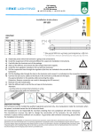
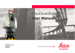
SINETZ P r o g r a m S y s t e m f o r S t e a d y S t a t e C a lc u la t io n o f F lo w D is t r ib u t i o n , P r e s s u r e D r o p a n d H e a t L o s s in B r a n c h e d a n d I n t e r m e s h e d P ip in g N e t w o r k s I n c lu d e s S I N E TZ f l u id SINETZ 3.7 Tutorial SINETZ Introduction - Editing a System Release 3.7 September 2014 Release 150608 SIGMA Ingenieurgesellschaft mbH Contents of this document are subject to change without notice. The manual is protected by copyright. No part of this document may be reproduced or transmitted in any form or by any means, electronic or mechanical, for any purpose, without permission. Specifications subject to change without notice. All of the mentioned products and brand names are trademarks or indexed trademarks of the respective manufacturers. Software-Support, German Software-Support, English ++49 (0) 2303 332 33 33 ++49 (0) 2303 332 33 44 Published by SIGMA Ingenieurgesellschaft mbH Bertha-von-Suttner-Allee 19 D-59423 Unna Germany Telephone +49 (0)2303 332 33-0 Telefax +49 (0)2303 332 33-50 E-mail: [email protected] Internet: www.rohr2.de www.rohr2.com [email protected] [email protected] SINETZ 3.7 Tutorial Page i Contents Contents 1 SINETZ Tutorial .........................................................................................................................................1-3 1.1 1.1.1 1.1.2 1.1.3 1.1.4 1.1.5 SINETZ test license (full featured) ..............................................................................................................1-3 Required data .............................................................................................................................................1-3 Settings .......................................................................................................................................................1-3 Installation...................................................................................................................................................1-4 Program start ..............................................................................................................................................1-4 License Terms & Conditions and Access Code ..........................................................................................1-4 1.2 Projects and Examples ...............................................................................................................................1-5 1.3 User support, hotline and ROHR2/SINETZ board ......................................................................................1-5 2 The SINETZ graphical user interface - Overview ...................................................................................2-1 3 Quick guide ...............................................................................................................................................3-1 3.1 3.1.1 3.1.2 Starting the program ...................................................................................................................................3-1 SINETZ data format and interfaces ............................................................................................................3-1 Create or open a SINETZ project ...............................................................................................................3-1 3.2 Settings .......................................................................................................................................................3-2 3.3 Geometry input ...........................................................................................................................................3-4 3.4 Components ...............................................................................................................................................3-9 3.5 Boundary conditions .................................................................................................................................3-12 3.6 Environment data ......................................................................................................................................3-13 3.7 Calculation and results .............................................................................................................................3-14 3.8 3.8.1 3.8.2 3.8.3 3.8.4 Output of results .......................................................................................................................................3-15 Calculation output – standard documentation ...........................................................................................3-15 Results at pipe segments..........................................................................................................................3-16 Results at nodes .......................................................................................................................................3-16 SINETZ report generation .........................................................................................................................3-17 4 SINETZ Tutorial projects ..........................................................................................................................4-1 4.1 SINETZ Tutorial - Training Example 1 ........................................................................................................4-1 4.2 SINETZ Tutorial - Training Example 4 ........................................................................................................4-1 5 Checking CAD/CAE import with SINETZ Interfaces ..............................................................................5-1 SIGMA Ingenieurgesellschaft mbH www.rohr2.com Page ii SINETZ 3.7 Tutorial Contents www.rohr2.com SIGMA Ingenieurgesellschaft mbH SINETZ 3.7 Tutorial Page 1-3 1 - SINETZ Tutorial 1.1 - SINETZ test license (full featured) 1 SINETZ Tutorial Thank you for reading this document, introducing into the work with the program system SINETZ. This manual is applicable to the SINETZ full license SINETZ test license We would be very pleased to provide you with a program license or viewer download. Please contact our sales department in Germany ([email protected]) or one of the ROHR2/ SINETZ sales partners (see www.rohr2.com for contact details). 1.1 SINETZ test license (full featured) The test license is identical to the full license including optional available modules and interfaces. The test license includes the entire capability of SINETZ and its modules and interfaces. The test license includes optional modules and interfaces which may be different from your inquiry/order and the quoted/delivered program. The test program is provided by download and can be used under conditions of non-commercial use. Running a test license requires a contact to the SIGMA test license server by internet connection. The technical requirements are specified in an installation document. Please contact us by email ([email protected]), use the contact form on www.rohr2.com or call us. A test license is provided - by sending a program package including license key (USB-plug) or - by an access to the SINETZ test license server. The following instruction shows how to get a test license with access to the SINETZ license server. 1.1.1 Required data We would be very pleased to provide you with a full featured test license. Please contact our sales department in Germany ([email protected]) or one of the ROHR2 sales partners (see www.rohr2.com for contact details). You will receive - a download link - a license access code 1.1.2 Settings The following settings are required for the access to the license server: make sure that port 1947 (UDP + TCP) is not blocked for the access to the test server (possibly is blocked by the Windows firewall!) SIGMA Ingenieurgesellschaft mbH www.rohr2.com Page 1-4 SINETZ 3.7 Tutorial 1 - SINETZ Tutorial 1.1 - SINETZ test license (full featured) 1.1.3 - 1.1.4 Installation Download and unzip the installation package. Copy all files into a directory on your hard disk. Start the installation in this directory by setup.exe and follow the instructions The test license may be installed parallel to existing ROHR2/SINETZ programs. In this case please use a different directory name and program group Program start Start the SINETZ application by a click on the program symbol or start the programs manually from the program directories: Program SINETZ Start the program in the test directory by running \SINETZW\sinetzw.exe. 1.1.5 License Terms & Conditions and Access Code - At first start a dialog window opens: - You are asked to accept the license conditions. The user agrees to the General Contract Terms of SIGMA GmbH, being basis of participation (copy upon request). Enter the access code which has been sent by the sales team. The program asks for an activation. Press OK here to activate by Internet. A manual input of the activation code is not required for a test license. - The test license now is prepared to run until the end of the test period. The status of the test license is checked by internet frequently. Please be sure to have an internet access when the program is running. Please note: the scope of delivery of the server test license may be not identical to the ROHR2/SINETZ standard release and the demo version! www.rohr2.com SIGMA Ingenieurgesellschaft mbH SINETZ 3.7 Tutorial Page 1-5 1 - SINETZ Tutorial 1.2 - Projects and Examples 1.2 Projects and Examples For an introduction into pipe stress analysis with SINETZ we are providing projects and examples to the user. sample calculations are stored in the../SINETZ/EXAMPLE/ directory after installation of a fullfeatured SINETZ license project files, explanations and movies of the SINETZ tutorial examples can be downloaded from the website www.rohr2.com in the Service area. They can also be accessed by the SINETZ program function HELP > Training videos. SINETZ test license and viewer: sample calculations are stored in the. ../SINETZ/EXAMPLE/ directory Please refer to topic 2 of this document for a detailed introduction into a calculation example Project editing by means of a full-featured test license Please note when creating projects using the test license program: projects are marked by TEST LICENSE. They can be opened and modified by a full program license. Projects, created by a full featured SINETZ license only can be opened and modified by means of a test license. 1.3 User support, hotline and ROHR2/SINETZ board All software commands are documented in the user manual and in the program online help, see Online help and Program documentation. Additional information sources are available in the Internet, e.g. ROHR2/SINETZ Forum incl. SINETZ FAQ (Frequently asked questions), see Help menu the user support providing advice on installation and application of the program (hotline-service) on workdays (Mondays to Fridays) from 9.00 - 16.00 (Central European Time). User support by email An email function, integrated in to SINETZ, enables to transmit program data directly (see menu Help |Support request). User support address SIGMA Ingenieurgesellschaft mbH Dept. Program-Support Bertha-von-Suttner-Allee 19 D-59423 Unna Germany Telephone and email Software-Support, German Software-Support, English Internet www.rohr2.de ++49 (0) 2303 332 33 33 ++49 (0) 2303 332 33 44 [email protected] [email protected] www.rohr2.com SIGMA Ingenieurgesellschaft mbH www.rohr2.com Page 1-6 SINETZ 3.7 Tutorial 1 - SINETZ Tutorial 1.3 - User support, hotline and ROHR2/SINETZ board www.rohr2.com SIGMA Ingenieurgesellschaft mbH SINETZ 3.7 Tutorial Page 2-1 2 - The SINETZ graphical user interface - Overview 2 The SINETZ graphical user interface - Overview The input window shows the piping system and the drawing created. All program functions are accessible by menu commands and symbols (icons). The title bar shows the name of the current project including complete path. The status bar represents the currently used program command and the selected system data. All elements of the user interface may be placed free on the screen. The textual calculation output is shown in the output window. SIGMA Ingenieurgesellschaft mbH www.rohr2.com Page 2-2 SINETZ 3.7 Tutorial 2 - The SINETZ graphical user interface - Overview www.rohr2.com SIGMA Ingenieurgesellschaft mbH SINETZ 3.7 Tutorial Page 3-1 3 - Quick guide 3.1 - Starting the program 3 Quick guide 3.1 Starting the program Start SINETZ by clicking the program icon. The geometry and all boundary conditions are entered via the graphical user interface. Create a new project or load an existing file by using - File| New, or - File| Open All inputs are made by a keyboard and standard mouse. 3.1.1 SINETZ data format and interfaces Open the following file types without additional interfaces: SINETZ project, (*.snp) SINETZ Neutral 2D-Interface format, Import of data from e.g. CAD systems etc. Neutral 3D-Interface, conversion of CAD-/CAE data by means of the Neutral 3Dinterface. DXFdata (*.nts) (*.ntr) (*.dxf) Open these types of files using an optional available interface program, depending on the availability of interfaces (see system contract). The demo program may include a reduced number of interfaces. PCF Intergraph PDS PASCE Autoplant (*.pcf) (*.n) (*.ntl) (*.pxf) We recommend to open an existing project or create a new SINETZ project: 3.1.2 Create or open a SINETZ project Program command File| open Open an existing SINETZ project or import one of the available file types. Alternatively the project may be taken from the list of last opened files. Program command File| new Create a new SINETZ project. The dialog window Project settings opens, where project related information and order details may be entered. Continue with 3.2, settings. SIGMA Ingenieurgesellschaft mbH www.rohr2.com Page 3-2 SINETZ 3.7 Tutorial 3 - Quick guide 3.2 - Settings 3.2 Settings At first, in the menu Options| Settings general settings are made. The dialog window Settings is shown automatically when a new system is opened. Pressure and mass units Select the pressure and mass units. The automatic determination of zeta-values at branches can be switched off. Project data Put in an order name, a page header and the number of lines per page and chose a language for your printer output of results. The graphic is printed in the same language as well. Graphic parameters Got to the Graphic tab to control the graphic parameters as paper size, scale, grid and settings of text representation and colors. An isometric grid may be activated. These settings can be modified during the project. For the example the standard settings are kept at first. Load case definition Define load cases in the dialog window Load Cases. The definition of load cases enables to analyze different operation states in one system. Boundary conditions (pressure, temperature, quantity injection, ...) are given to each load case separately. Depending on load cases the zetavalues of components (valves, shutter, ...) can be put in as well as pumps may be switched on and off. For each load case a medium as well as the precision grade and the maximum number of iterations may be defined. If a new system is created, the dialog window load case is shown automatically. www.rohr2.com SIGMA Ingenieurgesellschaft mbH SINETZ 3.7 Tutorial Page 3-3 3 - Quick guide 3.2 - Settings Pipe dimensions and insulation The menu Edit|-Dimensions is used to define the dimensions and insulation. The pipe dimension used to start or continue the input of the system need to be selected. The selected dimension is shown in the status bar. When entering a new system one dimension is displayed standardly. A mouse click on the pipe dimension opens the input window. Different colors and line width can be assigned to the pipes for a better survey. If heat loss is to be part of the calculation, the input of insulation parameters is required! SIGMA Ingenieurgesellschaft mbH www.rohr2.com Page 3-4 SINETZ 3.7 Tutorial 3 - Quick guide 3.3 - Geometry input 3.3 Geometry input The system has to be divided into pipe sections. A pipe section consists of a pipe segment with a constant diameter without branches. Create the pipe system by means of Edit| Draw. Duplicate parts of the system by copy and move Use the copy command to extend the piping system with symmetric partial systems. A partial system must be selected for this purpose. Given parameters of nodes and sections, e.g. dimensions and boundary conditions remain. The function Edit / Select is used to choose partial systems for further processing. Change the position of nodes by edit -move. If parts of the system are selected (highlighted), the nodes at all selected pipe sections are moved. www.rohr2.com SIGMA Ingenieurgesellschaft mbH SINETZ 3.7 Tutorial Page 3-5 3 - Quick guide 3.3 - Geometry input Selected part of the system, copied and inserted multiple After that the piping system can be completed individually by the draw function . Geometry, completed The pipe dimensions, shown in the status bar are assigned to the segments. If dimensions change they need to be corrected by Edit| dimensions. Alternative method: draw the complete geometry at first and assign the dimensions in a second step. SIGMA Ingenieurgesellschaft mbH www.rohr2.com Page 3-6 SINETZ 3.7 Tutorial 3 - Quick guide 3.3 - Geometry input Changing pipe dimensions Change the dimensions of pipes as follows: Select desired pipe sections. Use Edit| Pipe dimensions to choose the pipe dimensions. Selected segments, changing the pipe dimensions www.rohr2.com SIGMA Ingenieurgesellschaft mbH SINETZ 3.7 Tutorial Page 3-7 3 - Quick guide 3.3 - Geometry input Height parameters If there are height parameters at nodes, they may be entered in Properties | Nodes. If nodes have been selected before, the indicated heights are assigned to them. Assigning a new node height Use Show node heights to get a perspective representation of the heights. SIGMA Ingenieurgesellschaft mbH www.rohr2.com Page 3-8 SINETZ 3.7 Tutorial 3 - Quick guide 3.3 - Geometry input Pipe segment data The input of the piping system is done in a not-scaled way. Due to the given scale (see above, settings) the section length are calculated by the program. They may be altered by the user in Properties | pipe section. All pipe dimensions, shown in the status bar, are assigned to the pipe sections. If dimensions change, they must be edited in Edit| Dimensions . Revising segment data IN the highlighted segment the length, nominal width and type and number of bends can be entered or modified. www.rohr2.com SIGMA Ingenieurgesellschaft mbH SINETZ 3.7 Tutorial Page 3-9 3 - Quick guide 3.4 - Components 3.4 Components Adding zeta values Toolbar components Assign additional resistance coefficients and pressure loss parameters to pipe sections by Edit| Components. If there are more than one defined load cases, zeta values and Pressure loss parameters of the components may be indicated depending on load cases. This may be useful for the representation of different operation states with open and closed instruments. Insert reducers at nodes where dimensions change. Additional zeta value added SIGMA Ingenieurgesellschaft mbH www.rohr2.com Page 3-10 SINETZ 3.7 Tutorial 3 - Quick guide 3.4 - Components Pressure loss (e.g. by consumer loads) A pressure loss can be assigned by means of a component by the command Edit| components and a click on the segment. It is recommended to insert a pressure loss together with mass flow and medium density to convert them in to zeta values. The command Properties water/steam opens the corresponding dialog window. It is used to determine and display the properties of water and steam from steam table. Consumer load inserted as pressure loss If several load case have been defined, die zeta values or pressure loss definitions of the components can be inserted depending on the load case. By this way instruments, open or closed depending on operation state, can be modeled. A reducer can be inserted by a clock on the node by changing the dimensions. www.rohr2.com SIGMA Ingenieurgesellschaft mbH SINETZ 3.7 Tutorial Page 3-11 3 - Quick guide 3.4 - Components Pumps Pump with curve taken from database Characteristic curves can be stored in the database as far as the pairs of value are completed. Pumps can be inserted multiple. A pump can be rotated to change the working direction. Pumps can be switched off and on, load case depending. SIGMA Ingenieurgesellschaft mbH www.rohr2.com Page 3-12 SINETZ 3.7 Tutorial 3 - Quick guide 3.5 - Boundary conditions 3.5 Boundary conditions For each load case boundary conditions like pressure, quantity injection and temperature must be entered to the system. Select Boundary conditions from the toolbar load cases. Required is a minimum of one temperature value, pressure parameter and quantity injection. To get a calculable piping model the se inputs are required for pressure and quantity input: Usually each run through line end requires pressure or quantity: - one pressure value and one quantity injection with quantity to be calculated or - no pressure value and one quantity injection with defined quantity At in- and outputs with unknown flow volume a quantity injection using the option Calculate mass flow must be entered. The current quantities are calculated by the program then. At least one node with quantity injection using the option Calculate mass flow at each load case must be entered. If pressure and quantity are defined at an input or output (quantity <> 0), at other in- and outputs neither pressure nor quantity are allowed. Even in a closed system it is valid: In any case at one node the option "calculation of mass flow" needs to be assigned. Assigned boundary conditions: pressure, temperature and volume www.rohr2.com SIGMA Ingenieurgesellschaft mbH SINETZ 3.7 Tutorial Page 3-13 3 - Quick guide 3.6 - Environment data 3.6 Environment data If also the temperature loss needs to be part of the calculation it is required to enter environment data at each load case. These are environment temperature and wind velocity. The wind velocity is left in case of buried pipes. Selecting ambient data Environment data used to determine the heat loss. SIGMA Ingenieurgesellschaft mbH www.rohr2.com Page 3-14 SINETZ 3.7 Tutorial 3 - Quick guide 3.7 - Calculation and results 3.7 Calculation and results Calculation The SINETZ calculation starts by the command File| Calculate or by a click on the symbol Calculate in the standard toolbar. If there are several defined load cases, the dialog window Select Load Case appears where the load cases to be calculated can be highlighted. Results Calculation results can be plotted and presented in the form of a list or printed. To show the results you have to switch into the result mode by the Tool bar Mode. The calculation results generally display the results of one load case. Please specify the load case from the toolbar Load cases. Show the results of the analysis by means of Results | Output file or graphically by the command Results | Show results. Additionally it is possible to show a perspective representation by Results| Show pressure distribution and temperature distribution. www.rohr2.com SIGMA Ingenieurgesellschaft mbH SINETZ 3.7 Tutorial Page 3-15 3 - Quick guide 3.8 - Output of results 3.8 Output of results The output files may be exported in rtf or pdf format for documentation purposes. On the basis of factory templates or user defined templates you are able to create a complete Calculation report of the SINETZ analysis by means of the function Standard report. 3.8.1 Calculation output – standard documentation The SINETZ calculation core produces results by load case. Output of the results on a printer by means of file-print| print. The output file is printed when the outputfile window is active. Otherwise the graphic is printed. Store (export) the graphical representation by File-Export in DXF-file format. The graphic can be saved in metafile or dxf format or copied to the clipboard. For documentation or reports the analysis resultsIngenieurgesellschaft can be stored in file formats SIGMA mbH rtf or pdf. www.rohr2.com Page 3-16 SINETZ 3.7 Tutorial 3 - Quick guide 3.8 - Output of results 3.8.2 Results at pipe segments In the results mode the representation of the most important results at segments can be activated by - a double click on the pipe segment - using the symbol or using the function Properties| Segment .and a click on the pipe segment. All results, available in the segment can be shown by the list commands (see Properties| List data). In the dialog window Result segment the values are shown. The header of the dialog window shows the segment parameters name, AKN (start node) and EKN (end node) length. 3.8.3 Results at nodes In the results mode the representation of the results at a node can be activated by - a double click on the node - using the symbol or function Properties| Nodes and a click on the node. All results, available at the node can be shown by the list commands (see Properties| List data). www.rohr2.com SIGMA Ingenieurgesellschaft mbH SINETZ 3.7 Tutorial Page 3-17 3 - Quick guide 3.8 - Output of results 3.8.4 SINETZ report generation The report template includes links to SINETZ text and graphic output of general data load cases temperature loss pressure drop results graphics After recalculating the piping system the modifications of the current analysis are taken over into the report. Automatically refreshed after re-calculation SIGMA Ingenieurgesellschaft mbH www.rohr2.com Page 3-18 SINETZ 3.7 Tutorial 3 - Quick guide 3.8 - Output of results www.rohr2.com SIGMA Ingenieurgesellschaft mbH SINETZ 3.7 Tutorial Page 4-1 4 - SINETZ Tutorial projects 4.1 - SINETZ Tutorial - Training Example 1 4 SINETZ Tutorial projects The project files, explanations and movies of the SINETZ tutorial examples can be downloaded from the SINETZ website www.rohr2.com. 4.1 SINETZ Tutorial - Training Example 1 Pressure loss calculation - only one section different load cases and boundary conditions Input data Geometry: length 50 m, 10 bends 90° with long radius Dimension: DN200 219.1 x 6.3 mm Roughness: 0.1 mm Boundary conditions refer to different calculation options Options option 1: pressure loss calculation, medium water 20°C / 5.0 bar / 250 t/h option 2: pressure and temperature loss calculation, medium steam 200°C / 5.0 bar / 30 t/h option 3: flow calculation, pressure loss is given 200°C / 5.0 bar 4.2 SINETZ Tutorial - Training Example 4 Heat Exchanger - Pump - Consumer 1-4 (closed loop) Load case Operation1 - SINETZ-Training - Example 4 - 1 x 100% pump + 2 x 50% pump - 4 consumers - 100% pump in operation, 50% pumps idle SIGMA Ingenieurgesellschaft mbH www.rohr2.com Page 4-2 SINETZ 3.7 Tutorial 4 - SINETZ Tutorial projects 4.2 - SINETZ Tutorial - Training Example 4 www.rohr2.com SIGMA Ingenieurgesellschaft mbH SINETZ 3.7 Tutorial Page 5-1 5 - Checking CAD/CAE import with SINETZ Interfaces 5 Checking CAD/CAE import with SINETZ Interfaces The program system ROHR2 offers a wider angle of interfaces to CAD and CAE systems. For details please refer to the ROHR2 Interface feature list. SINETZ includes the interfaces: - Neutral 2D-interface for import from ROHR2 - Neutral 3D-interface CAD Interface for the import from CAD systems like AVEVA PDMS, CADISON, RC-Planet, MPDS4, HICADnext, etc - DXF files Additional modules are available. Some of them are part of the demo program *). Load the data by means of File| Open command and get an overview on the capacity of the import interfaces. *) some of the interface modules are optionally available products. www.rohr2.com SIGMA Ingenieurgesellschaft mbH Page 5-2 SINETZ 3.7 Tutorial 5 - Checking CAD/CAE import with SINETZ Interfaces www.rohr2.com SIGMA Ingenieurgesellschaft mbH