1
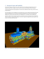
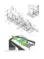
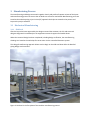
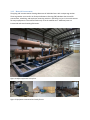
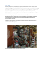
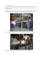
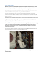
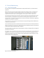
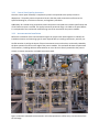
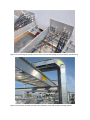
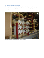
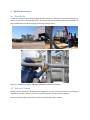
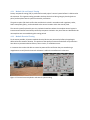
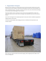
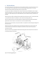
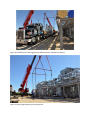
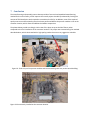
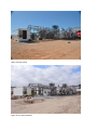
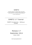
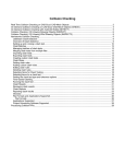
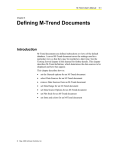
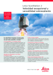
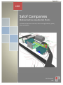
Appendix I LNG Salof Companies Modularized Gas Liquefaction Plants A modularized approach to save costs, while increasing productivity, quality, safety, and schedule. Salof Companies LNG TableofContents 1 Introduction .......................................................................................................................................... 2 2 Conceptual Layout and Feasibility ........................................................................................................ 3 3 Manufacturing Process ......................................................................................................................... 5 3.1 3.1.1 Skid Steel ............................................................................................................................... 5 3.1.2 Material Procurement ........................................................................................................... 6 3.1.3 Piping ..................................................................................................................................... 7 3.1.4 Module Setup ........................................................................................................................ 8 3.1.5 Pressure Testing .................................................................................................................... 9 3.1.6 Piping Insulation .................................................................................................................... 9 3.2 Electrical Manufacturing ............................................................................................................. 10 3.2.1 Control Panel Assembly ...................................................................................................... 10 3.2.2 Control Panel Quality Assurance ......................................................................................... 11 3.2.3 Instrumentation Installation ............................................................................................... 11 3.2.4 Electrical and Control Wiring .............................................................................................. 12 3.3 4 Mechanical Manufacturing ........................................................................................................... 5 Module Painting and Coating ...................................................................................................... 14 Quality Assurance ............................................................................................................................... 15 4.1 Plant Set Up ................................................................................................................................. 15 4.2 Electrical Testing ......................................................................................................................... 15 4.2.1 Module I/O and Control Testing ......................................................................................... 16 4.2.2 Module Electrical Testing .................................................................................................... 16 5 Preparation for Transport ................................................................................................................... 17 6 Field Installation .................................................................................................................................. 18 7 Conclusion ........................................................................................................................................... 20 1 Introduction Salof is a world leader in cryogenic plant design and fabrication with a proven track record of supplying fully integrated modularized plants that exceed customer requirements and meet all required local, federal, and international codes. Salof has delivered several LNG plants and over 110 CO2 Liquefaction Facilities installed worldwide, since 1977. We are located in New Braunfels, Texas, just a few minutes outside of San Antonio, on a 9 acre plot that is owned by Salof, which contains offices, 300,000 FT2 of enclosed manufacturing space, and additional space for outdoor construction and full plant assembly as required. Our philosophy is to be on the leading edge of technology with regards to our plant design, manufacturing, and management techniques. Our designs start using the industry standard Aspentech Hysys® modeling. Our process design team will run multiple iterations to insure our design will meet the project requirements under differing scenarios, including off‐design cases and turn down scenarios. “Smart P&ID’s” are our standard, taking conventional P&ID’s a step further by integrating all tagged items into a project database. Bentley Systems Autoplant P&ID® allows this attribute data to be passed on to the client after the project is completed for process safety and asset management systems. 3D modeling allows pre‐manufacturing walk through and allows maintenance and safety design considerations to be integrated into the design. Our designers model all components of the plant to provide our clients with a comprehensive pre‐manufactured view of their plant. Customized PLC/OI and DCS solutions are tailored to clients needs with our in‐house team. FREE technical support via remote internet connection with customized security protocol as client required is standard. Commissioning, start up, and operator training using our in house personnel. Customized documentation integrating current client systems and operating procedures is also available. Warranty, parts, and onsite technical service is provided via our sister company River City Industrial Refrigeration Company, Inc. (RCIR). Salof has the expertise and experience, combined with capability and capacity to undertake and deliver this project successfully. Our current client list includes all of the major industrial gas suppliers and can attest to our value added approach. 32 years in the industry gives Salof a proven track record of “Meeting Customer Requirements with Superior Solutions”. 2 ConceptualLayoutandFeasibility The project managers and supervisors work closely with the 3‐D design and engineering teams to develop a layout that is compact, practical, and will minimize field installation work. During the preliminary design phase major equipment is located on the skid bases and the main process lines are interconnected. This initial design is then reviewed by the entire project team, which includes representatives from the engineering department, the mechanical manufacturing department, the electrical manufacturing department, and the commissioning and service departments. This multilevel and multidiscipline approach confirms that the design is practical to manufacture while maintaining the ease of operation and serviceability of a plug‐and‐play design. Our clients are given the opportunity to participate in this process to the extent that they chose. Figure 1: The complete plant design begins with the conceptual layout Figure 2: Each module is detailed and reviewed for operability. 3 ManufacturingProcess The manufacturing and design teams work together closely and perform frequent reviews of the layout and manufacturing process to ensure that no details are missed or overlooked. Manufacturing prints are issued to the workshop using a just‐in‐time (JIT) approach that helps to streamline the process and improve the project schedule. 3.1 MechanicalManufacturing 3.1.1 SkidSteel After the layout has been approved by the design team and the customer, the 3‐D and structural designers begin work immediately on the equipment structural support and module bases. When the structural design has been completed, including design verification, the manufacturing drawings are issued to the workshop for construction via the controlled document system. This design/manufacturing approach allows work to begin on the skid steel base while the detailed piping design work continues. Figure 3: Skid steel is the first phase of the modular manufacturing process 3.1.2 MaterialProcurement The piping and instrumentation drawings document all individual items with a unique tag number. These tag number are stored in our Enterprise Resource Planning (ERP) database that is used for procurement, scheduling, and employee resourcing activities. Operating in a just in time environment the major equipment is received and set directly on to the module steel. Additional parts are inventoried and stored awaiting fabrication. Figure 4: Major equipment set in place. Figure 5: Equipment inventoried and ready for use. 3.1.3 Piping The piping manufacturing process begins by employing qualified welders who are required to pass a stringent 6G welding test as outlined by ASME. There are several techniques employed during the piping assembly process including shielded metal arc welding (SMAW) and gas tungsten arc welding (GTAW). All welds are visually inspected and x‐ray tests are performed as required by ASME standards. Quality is controlled and ensured through the use of weld maps that correlate quality tests with a given welders identification number/stamp. When practical the piping assemblies are fabricated on the workshop floor before they are inserted into the module. These piping assemblies are then fit up and welded in place as required. This technique increases efficiency by eliminating many time‐consuming position welds that can compromise ergonomics, quality, and safety. Installation of Electrical devices, instrumentation, and pumps and motors begins when the piping installation reaches 50% completion. Figure 6: Piping spools installed and ready for pressure testing. 3.1.4 ModuleSetup During the manufacturing process the modules are set up and positioned as they will be in the field. At this time the modules are leveled, using a site level, and interconnecting pipe and/or pipe racks are connected and test fit. In instances where there are height constraints at our manufacturing facility dummies and/or mockups are manufactured to ensure that the upper and lower modules will fit together as designed. Figure 7: Multiple process modules are set up in the manufacturing space before piping begins. Figure 8: Equipment "dummies" are created where required to interconnect equipment. 3.1.5 PressureTesting Before the pressure test is allowed to begin the manufacturing manager and/or supervisor will ensure that the Salof companies HSE procedures are followed and that all team members involved in the procedure have been briefed, to ensure employee safety at all times during the pressure test. The manufacturing manager and/or HSE coordinator will supervise the pressure test to ensure that it conforms to the Salof companies’ pressure testing procedure and requirements. During the preparation stages of the pressure test the required instrumentation is set up and its calibration is confirmed. Next the final piping assembly is inspected to ensure that proper bolting and gaskets are installed. The pressure test is executed in stages that allow any system leaks to be identified and corrected before the pressure is increased to the next stage. This incremental approach to pressure testing increases quality and safety while providing a leak free process module. 3.1.6 PipingInsulation With the pressure test and any other required nondestructive testing (NDT) complete the process piping is ready to be insulated. The insulation thickness is selected based on the process design, thermal requirements, and customer specifications. The design thickness of the insulation is verified using software tools such as 3E plus. The insulation and protective jacketing is installed by professionals using pre‐molded piping materials, block material, and wool products as directed by the engineering team. Figure 9: Calcium silicate block insulation is installed on vessels. Preformed piping insulation is miter cut to create custom fit. 3.2 ElectricalManufacturing 3.2.1 ControlPanelAssembly All control panels are designed and manufactured to comply with NFPA, NEC, UL, and state and local regulations. Before construction of the control panels begins the panel shop manager receives a controlled set of drawings, as prescribed by the Salof Companies ISO process, from the design team that includes a complete bill of materials, layout, and wiring diagrams, and any specific customer requirements. The control panel assembly process starts with a technician mounting the required equipment onto the enclosure subpanel, or backing panel, which includes PLC hardware, power supplies, wire duct, and wiring terminals. The subpanel is removed from the enclosure to facilitate increased access, ergonomics, and quality of the equipment installation. The panel devices are then wired and interconnected per the project drawings and each individual wire is labeled for easy identification. Custom identification placards are created for each panel that contains pertinent information about the design and specification of a given panel. Additional placards are installed on the exterior of the panel to include customer logos and safety warnings, as required. The enclosure doors are outfitted with any required buttons, switches, or displays before the subpanel is reinstalled in the enclosure. The subpanel is then reinstalled into the enclosure and secured. A grounding wire is connected from the hinged door on the enclosure to the subpanel for electrical safety. Finally the wiring diagrams used to construct and assemble the panel are inserted in the door pocket before the panel continues on to the electrical quality assurance department. Figure 10: Main PLC control panel. 3.2.2 ControlPanelQualityAssurance Once the control panel assembly is complete the panel is transported to the quality assurance department. The quality assurance personnel ensure that the panel construction conforms to the specified drawing set, all relevant customer, and regulatory standards. Additionally all screwed wiring connections within the panel are torqued to the vendor specification and a final checkout report is created. The quality assurance personnel assign a UL label to the panel before it is transported to the mechanical manufacturing area to be mounted on the process module. 3.2.3 InstrumentationInstallation Before the installation of the instrumentation begins our project team works together to identify the installation location and mounting type for each required device, including transmitters, switches, etc. Careful attention is paid to the layout of these instruments to ensure that they can be easily viewed by the plant operations staff from the edge of the process module. This evaluation dictates the placement of transmitters, including decisions about whether or not a device is directly mounted to the process stream or remote mounted on a suitable instrument stand. Figure 11: Remote mounted instrumentation racks allow operations staff to easily view the device from the skid edge. 3.2.4 ElectricalandControlWiring The electrical cable and conduit/cable tray routing is predetermined by the design team before installation begins. The installation team determines the size of conduit and/or cable tray based on the number of conductors that each conduit/cable tray is required to contain. Dissimilar voltages are segregated to prevent crosstalk and/or interference. Shielded cable is used to carry analog signal and each multi‐conductor cable is identified with a permanent sleeved wire label. All conduit and cable tray is secured to the module with brackets and clamps as required. In instances where conduit is used, the conduit hubs, pull fittings, and junctions are of a heavy duty construction and equipped with gaskets to prevent moisture ingress. Liquid tight flexible conduit is used to connect the end device to the main conduit trunk. This flexible connection allows the device to be easily field serviced and dampens the effect of vibration, while providing a protective sheath to the device wiring. Figure 12: Module cable tray and wiring from panel to device. In situations where Salof is providing a motor control center (MCC) and/or control room building the electrical and instrument cable connections used to interconnect these buildings to the process modules are test fit at our factory. This includes the installation of cable tray and conduit supports between the process modules and the control buildings as well as prefabricated electrical penetrations into the building. This additional layer of electrical preparation expedites the field set up and commissioning process while controlling quality by allowing wiring issues to be identified and corrected before the process modules are delivered to the customer location. Figure 13: Field wiring connections are test fit to the control buildings to increase quality and efficiency. Figure 14: A labyrinth of cable tray keeps the installation clean and the plant running smooth. 3.3 ModulePaintingandCoating After the mechanical and electrical manufacturing work is complete the process modules are prepared for paint. The paint and coatings that are selected for a given project are designed to provide adequate corrosion protection and are suitable for outdoor use. Figure 15: The process module is "taped off" and ready for paint. 4 QualityAssurance 4.1 PlantSetUp In order to confirm the plant will go together quickly and easily in the field we are able to assemble the plant in our yard as if it was the project site. This allows client confirmation of entire plant assembly, as well as 100% factory acceptance testing of the plant control system. Figure 16: Transporting, rigging, and aligning module to module connections. 4.2 ElectricalTesting Electrical quality assurance is divided into two categories. The first of these is the control system factory acceptance test (FAT), while the second is the electrical power quality assurance program. These two steps are often executed in parallel to improve the project schedule. 4.2.1 ModuleI/OandControlTesting Factory acceptance testing (FAT) is performed on each project’s control system before it is delivered to the customer. This rigorous testing procedure involves device level wiring integrity checks (point‐to‐ point) and complete control system functionality verification. The point‐to‐point I/O check verifies that each device is wired in accordance with regulatory codes, Salof's own quality policy, and terminated to the correct location within the control panel. The control system functionality test is a simulation‐based test where the complete control system is interconnected and its functionality verified by computer simulation. Any items that are identified to be noncompliant are corrected during this testing period. 4.2.2 ModuleElectricalTesting To the extent possible, all process module electrical devices are powered up before the package is delivered to the customer location. This portion of the quality assurance method will verify that there have been no premature device failures, short‐circuits, or installation errors. In instances where electrical devices cannot be powered for verification they are tested using a megohmeter to verify that the internal resistance is within the manufacturer’s tolerance. Figure 17: Control room completion and control system testing. 5 PreparationforTransport Before the process modules are transported the electrical and instrumentation cables that are used to interconnect the process modules to the MCC/control building are disconnected, clearly identified, and safely stored before shipping. The cable trays used to interconnect the process skids and these buildings are removed, labeled, and packaged for loose shipment. The process modules are then crated and in many instances shrink‐wrapped before transport. This preservation step ensures that there will be no damage to the skids before they arrive at the customer location. Items which are designated to be shipped separately from the process skids are loaded into appropriate shipping containers and secured. Finally the completed module and/or shipping containers are loaded up for transportation to the customer location. Figure 18: Process module crated for international shipping. Shrink‐wrapped process modules can be seen in the background 6 FieldInstallation The manufacturing process described above has been perfected with the successful execution of more than 130 projects to create high‐quality and easy to operate plug‐and‐play facilities. This section describes the field installation and setup process for a given facility. As the process modules are delivered to the customer location they are offloaded from the transport vehicles and installed on concrete slabs and/or pilings. Next the process piping is flanged together with the pipe rack and/or adjacent process module before the process modules are finally anchored to the concrete. While the process modules are being interconnected and secured to the concrete. The ship loose items are unpacked and installed. This includes air coolers and interconnecting cable trays. With the mechanical portion of the field installation complete and all process piping connected and tightened the electrical cables are connected to the control room/MCC building. When the electrical connections, the process modules are complete the commissioning team begins the final I/O check out. While the electrical team completes the pre‐commissioning procedures for the control system and electrical devices the mechanical team completes the leak test to ensure that all of the process connections are tight. With pre‐commissioning completed the Salof commissioning team works closely with the customer to introduce process gas to the facility. Figure 19: Sample rigging diagram. Figure 20: Qualified Crane and rigging teams offload process modules into position Figure 21: Piping aligned during the setup process 7 Conclusion The manufacturing and assembly process above provides a fast‐track and expedited manufacturing method for the entire facility, which improves the overall project schedule by substantially limiting the amount of field installation work required to commission the facility. In addition, most of the required quality assurance and functionality tests have been performed before the process modules arrive at the customer location, which allows for additional schedule compression. The photos below provide a strikingly similar view of the plant set up at the Salof factory when compared to the final installation at the customer location. This project was executed using the methods described above, which culminated with a high quality product that met a very aggressive schedule. Figure 22: Final set up of the process modules and interconnecting cable tray to the control building Figure 23: Permanently installed at the customer location. Figure 24: Shop set up Figure 25: On site assembled.