1
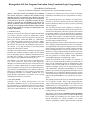
Retargetable Self-Test Program Generation Using Constraint Logic Programming
Ulrich Bieker, Peter Marwedel
University of Dortmund, Department of Computer Science, D-44221 Dortmund, Germany
Abstract - This paper presents new techniques in two different
areas. Firstly, it proposes a solution to the problem of testing
embedded processors. Towards this end, it discusses the automatic generation of executable test programs from a specification
of test patterns for processor components. Secondly, the paper
shows how constraint logic programming (CLP) improves the
software production process for design automation tools. The
advantages of CLP languages include: built-in symbolic variables
and the built-in support for constraints over finite domains such
as integers and Booleans.
1. INTRODUCTION
During the recent years, there has been a significant shift in the
way complex electronic systems are implemented: various
types of embedded processors are being used in many designs.
These types include: off-the-shelf DSPs (e.g. TMS320C25
[27]), application-specific instruction set processors (ASIPs,
see e.g. [2]), application-specific signal processors (ASSPs)
and in-house core processors. The advantages of these processors include: a very high flexibility in performing design
changes and a short time-to-market.
This shift in the implementation technology has largely been
ignored by the scientific community, despite the fact that the
tools for designing systems containing embedded processors
are rather poor. Compiler as well as simulation support for
these systems require significant enhancements [18].
The situation is even worse when it comes to testing these systems. These systems are tested with ad hoc approaches,
although it is well-known that processors can be tested systematically by running sophisticated test program diagnostics.
Such test programs are used extensively for mainframe processors, but less so for embedded processors. Moreover, due to the
high price of mainframes, it was acceptable to generate these
test programs manually. For consumer products, this is no
longer adequate and alternate, cost-effective ways of testing
embedded processors have to be found.
2. RELATED WORK
Systematic ways for testing microprocessors were first
described by Abraham et al. [26, 7]. Their proposal relied on
functional testing, i.e. it did neither require nor exploit knowledge about the internal structure of the processor to be tested.
After some initial enthusiasm it was recognized that this
resulted in a low efficiency and a poor coverage of real faults.
Furthermore, this method was never integrated into a CAD system.
The interesting approach of Lee and Patel for testing microprocessors [17] uses the internal structure and a bidirectional
discrete-relaxation technique, but does not aim at generating
self-test programs.
This was different for the work on MSST by G. Krüger [15,
16]. Krüger exploited knowledge about the internal processor
structure and consequently was able to generate more efficient
test programs. MSST is a tool for hierarchical test generation:
the user can specify test patterns for the processor components
and MSST then produces executable programs generating
these patterns and monitoring the response. MSST was actually
used for testing a Nixdorf processor.
MSST is possibly the first tool with the functionality described
above, though its implementation has some severe limitations.
It is implemented in an imperative language (Pascal) and thus
suffers from the poor support of symbolic variables, automatic
memory management and a low-level description style. Furthermore it is a large program and hard to maintain. Due to the
above reasons MSST cannot be adopted to new requirements
(like the generation of external stimuli, variable instruction
word lengths and support of multiple logic values).
Instead of incrementally trying to improve the situation, we
came to the conclusion that the problems just mentioned are
inherent in the traditional approach for implementing (CAD)
software. Tools for VLSI CAD systems, commonly written in
imperative languages, consist of a very large amount of source
code. Maintenance, portability and adaptability are recurring
problems. We realized that programming should proceed at a
much higher level of abstraction and hence started to look at
software technologies which provide a fundamentally different
approach. We found CLP to be very well suited to our requirements.
Test program generation relies heavily on backtracking and the
use of symbolic variables. Hence, logic programming languages such as Prolog provide a higher level of abstraction for
implementing tools. Correspondingly, it was used by several
researchers for this purpose [13, 25, 8]. Unfortunately, the execution mechanism of standard Prolog results in a lot of backtracking and long execution times.
The situation is different for Constraint Logic Programming
(CLP) languages [5], which became recently available (Prolog
III [23], CHIP [9], ECLIPSE [10]). CLP systems come with
built-in mechanisms for solving constraints over various
domains. Satisfiability checkers support Boolean constraints
and IP-solvers support integer domains. Hence, tools can be
implemented at a higher level of abstraction. For example, it is
possible to take advantage of the bidirectionality of clauses and
simulate logic gates in both directions. In contrast to pure Prolog, no backtracking is required for forward simulation. Furthermore, several problems can be handled concurrently by
specifying the subproblems with constraints and solve them in
one step instead of solving subproblems sequentially.CLP languages have been used for test generation [24] for the gate
level. Our work is the first one using CLP languages at the register transfer level.
It turns out that the techniques we propose can also be applied
for retargetable code generation for general programming languages [11, 12, 18, 21, 22, 28]. In fact, our techniques are capable of compiling a restricted set of programs into machine
code.
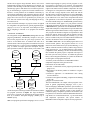
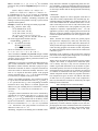
3. RESTART: OVERVIEW
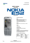
The retargetable compiler RESTART (REtargetable Self-Test
progrAm geneRaTion), automatically compiles a user specified self-test program onto the given target processor. The
result is an executable micro- or machine code and a set of
external stimuli. Generated programs are intended to be used as
internal off line tests e.g. after a processor restarts. RESTART
(Fig. 1) contains two inputs (processor description, test program specification) and two outputs (binary code, stimuli). We
HDL
TCL
hardware
description
test code
specification
language
front-end
front-end
circuit analysis
retargetable self-test code generator
binary
code
Fig. 1
self-test
program
stimuli
primary
input
pattern
use the description of the target architecture (hardware) and the
test program (software) as inputs. The target architecture
(processor) is expected to be described at the register transfer
level by a hardware description language (VHDL [14] or
MIMOLA [20]).
TCL (Test program speCification Language) serves as a com-
fortable input language to specify self-test programs. A selftest program is specified by a test engineer, well acquainted
with the RT structure of the processor. It is expected that a test
engineer runs ATPG tools for each RT component to be tested,
resulting in a set of test patterns for each RT component. Therefore, the fault coverage depends on the ATPG tool and the
internal structure of the RT component to be tested. RESTART
will achieve 100% fault coverage if the test patterns provided
by the ATPG tool covers 100% of the component faults and if
code generation is successful for all patterns. The test patterns
are made available using TCL and RESTART generates binary
code and stimuli which applies every test pattern to the RT
components and checks the response. In this way, RESTART is
a hierarchical test generation tool and RESTART based on
single fault assumption, is independent of a special fault model.
With our approach the obtained fault coverage depends on the
TCL program. The human test engineer is responsible for: fault
model, test strategy, fault coverage and test length. If specific
hardware features for increasing the testability (e.g. a scan
path) is available in the processor and described within the RT
structure, this hardware can be used by RESTART.
The result of RESTART is an executable program and a set of
external stimuli patterns. The program consists of a set of
instructions. Each instruction is a pair (Label, BitString), i.e. an
address within the instruction memory address range and a bit
string consisting of 0, 1, X. A stimuli pattern is a triple (PrimaryInputName, Time, BitString). The time at which the bit string
must stimulate the primary input is computed with respect to
the clock cycle time of the processor. To validate the generated
binary code an integrated simulator [6, 4] is able to simulate the
circuit together with program and stimuli.
A summary of the main features of RESTART includes:
a)Optional compaction of the generated code.
b)Generation of external stimuli.
c)Provides a comfortable self-test program specification language (TCL).
d)Declaration of an arbitrary number of variables in a register
component.
e)Concurrent application of transformation rules during
resource allocation.
f) Concurrent and global scheduling, compaction and binding
of the code.
g)Support for residual control.
The task of RESTART is to compile self-test programs. Compared to general programming languages, TCL is just a
restricted language. RESTART exploits the special features of
TCL programs to efficiently generate code for a wide range of
architectures. Self-test programs contain a large amount of
conditional jumps, comparison operations and constants (the
test patterns) to be allocated. Therefore RESTART has knowledge about a set of transformation rules, e.g. for IF statements
and comparison expressions. The special features of
RESTART which are helpful to compile self-test programs are:
1. Compaction of the generated code is optional. The compaction phase can be switched off to simplify subsequent fault
localization. If many instructions are executed in parallel, it
could be more difficult to localize a fault.
2. Generation of external stimuli is possible, because the code
generator must be able to allocate constants for all signals
including primary inputs.
3. To deal with different hardware realizations for conditional
jumps and comparison operations, a concurrent application
of transformation rules during resource allocation is performed (i.e. code selection and resource allocation are coupled).
4. In order to allocate constants efficiently, potential constant
sources and the paths from these sources to certain destinations are precomputed in a circuit analysis phase.
The remaining part of the paper is organized as follows: Section 4 describes the inputs of the system: hardware and test
specification. Section 5 contains the detailed description of the
retargetable code generation process. Section 6 shows the
experimental results followed by the conclusions.
4. INPUT SPECIFICATION: HARDWARE AND SOFTWARE
4.1 PROCESSOR DESCRIPTION
For the specification of the target processor we use structural
models. Datapath and controller must be completely described
with MIMOLA or VHDL. Hardware descriptions must contain
RT modules, their behavior and their interconnections. From
this we generate an intermediate tree based format, representing the target structure as a netlist of RT modules and the
behavior of every RT module as a tree (Fig. 5).
4.2 SELF-TEST PROGRAM SPECIFICATION
TCL is an imperative language in which the following kinds of
test statements are allowed to specify a self-test program (#
precedes a hexadecimal number; % precedes a binary number;
a variable location is referred to by <ComponentName>/<VariableName>):
•An Initialization causes the compiler to produce code for
loading a register or one cell of a memory with a constant initialization value.
Examples: RAM/cells[0] := #FF; REGISTER/store := 17;
•A Read Test makes the compiler produce code for testing if
a memory cell or a register contains a certain value.
Examples: TEST RAM/cells[0] = #FF;
TEST REGISTER/store = 17;
•An Initialization and Read Test combines an initialization
with a read test, i.e. the generated code first loads the specified
location with a value and then checks if it really contains that
value.
Examples: TEST RAM/cells[0] := #FF;
TEST REGISTER/store := 17;
•A Component Test makes the compiler produce code for
testing the functionality of any module, i.e. the related module’s input ports are stimulated with the specified values, and
then the outputs are checked for correctness. The programmer
needs only to specify the input values which should be hierarchically generated by a test pattern generator. An integrated
structure simulator calculates the corresponding output values.
An underscore may be used to denote a port of the module
which is not relevant to the test whereas X denotes a binary
don’t care.
Example: TEST ALU(%00,_, #FF);
•A Loop is used to apply one of the first four kinds of statements several times with one argument iterating over a range
of values. Examples:
FOR adr := 0 TO 15 DO RAM/cells[adr] := adr;
FOR adr := 3 TO 10 DO TEST RAM/cells[adr] = #A;
FOR i := 3 TO 10 DO TEST RAM/cells[i] := #A;
FOR i := 0 TO 3 DO TEST ALU(i, #FF, #AA);
The meaning of the keyword TEST is the following:
RESTART is directed to generate code that checks if the output
ports of a certain component are as expected. Therefore a conditional jump is generated:
IF component answer = expected answer
THEN increment program counter ELSE jump to error label;
If no error occurs, the program continues with the execution of
the next instruction of the self-test program, otherwise a jump
to an error procedure is performed. TCL allows the specification of all kinds of tests including memory test loops.
5. RETARGETABLE COMPILATION OF SELF-TEST PROGRAMS
We briefly discuss the circuit analysis phase (Fig. 1) followed
by the main part of the work: retargetable compilation of selftest programs.
5.1 CIRCUIT ANALYSIS
In the circuit analysis phase the given processor is analysed
and a subset of the instruction set is extracted. The result is a
list of microoperations the processor can perform and contains
e.g. the following operations: register transfer moves, conditional and unconditional jumps, counter increment operations,
etc. The considered subset is powerful enough to deal with the
compilation of TCL programs as described above.
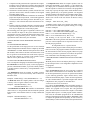
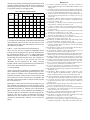
5.2 RETARGETABLE CODE GENERATION
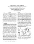
Fig. 2 shows the program flow of the retargetable compiler. A
hardware description, the output of the circuit analysis phase
and the TCL program serve as inputs. The code generation
phase described in the next subsection computes a relocatable
program. With respect to a certain program counter initialization value, the relocatable program has to be scheduled and
linked to a designated program start address. RESTART is able
to compact the generated code optionally, in order to allow a)
detailed analyses of the hardware and b) subsequent fault local-
circuit
analysis data
TCL test
specification
IF
condition
code generation
program start
address
program counter
init value
With all generated instructions do:
1. Disable unused memories and registers if possible.
2. Disable unused tristate drivers if possible.
3. Add increment program counter or unconditional jump
operation if the instruction is not a conditional jump.
ELSE
increment
label
Fig. 3
read PC
control
scheduling, (optional) compaction, binding
THEN
label1
label2
label3
condition (from datapath)
clock
PC
MUX
PC +
Next
PC
PC
Instruction
Memory
RT structure
netlist
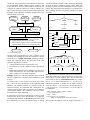
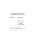
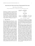
from the destination (program counter) backwards through the
circuit to the sources (condition, program counter, label). The
resulting instruction contains a load operation for the program
counter. The control input of the multiplexer is justified with 5.
Above example illustrates one possible realization of a TEST
statement.
load PC
Program
Counter
ization. The user is asked if the code should be compacted or
left uncompacted. Finally unused registers, memories and
tristate bus drivers must be disabled and the instructions are
composed to complete control store words by adding a program counter increment or jump operation (with respect to the
realization of the controller). An absolute program and a set of
external stimuli is the result.
control
word
Incrementer
Fig. 4
binary code
Output NextPC
stimuli patterns Fig. 2
5.2.1 CODE GENERATION
The task of the code generator is to map a sequence of TCL
statements onto the hardware. Each TCL statement is decomposed into a set of simple instructions consisting of assignments and conditional jumps. The main idea of the code
generation algorithm is as follows:
1. A simple instruction can be represented as a tree.
2. The behavior of every RT component can be represented as
a tree.
3. Retargetable compilation means: Mapping of a sequence of
simple instruction trees to a netlist where each node consists of a behavior tree of an RT component.
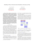
Example: Assume, the following conditional jump statement
has to be compiled onto a processor with a controller as given
in Fig. 4:
IF condition THEN increment program counter ELSE jump to label;
Fig. 3 shows the tree representation of the conditional jump
statement. The controller consists of a program counter, an
instruction memory, an incrementer and a multiplexer. The
next state of the program counter is selected by the multiplexer
control signals (control: 3 bits; condition: 1 bit). Fig. 5 shows
the behavior tree of the multiplexer.
IF statements are nested in a CASE construct to allow a conditional selection of one of two input branches. To compile the
conditional jump statement, an allocation routine has to search
for a multiplexer (i.e. a (sub-) tree as shown in Fig. 3), starting
case
control of 0
...
...
of 1 of 2 of 3 of 4
IF
condition THEN
Fig. 5
label 1
...
...
ELSE
PC+
...
of 5
...
IF
condition THEN
ELSE
PC+ label 1
Due to the fact that a retargetable compiler has to deal with different target architectures, different alternatives to map simple
instruction trees on RT behavior trees must be taken into
account. This is done by transformation rules. E.g. a statement X := Y+1 can be transformed to X := increment(Y). A
comparison operation, as needed for the TEST statement,
(component answer = expected answer) can be transformed to
((component answer - expected answer) = 0). Even loops can
be transformed:
<label>: REPEAT <block> UNTIL <condition>;
(* can be transformed to: *)
<label>: <block>;
ProgramCounter := IF <condition>
THEN increment(ProgramCounter) ELSE <label>;
To represent transformation rules for simple instructions we
use structural constraints implemented in CLP. Consider the
following definitions:
Def. 1: Let V = {X1, ..., Xn} be a finite set of variables, which
take their values from their finite domains D1, ..., Dn. A constraint c(Xi1, ..., Xik) between k variables from V is a subset of
the Cartesian Product Di1 × ... × Dik.
The domain of variables within structural constraints is the set
of trees, whereas the domain of variables within linear constraints is the set of integer numbers.
Def. 2: Let X1, X2 be two variables, both variables representing
a tree. A transformation rule for a simple instruction is a
structural constraint tr(X1, X2).
The meaning is: The tree X1 can be transformed to the tree X2
if tr(X1, X2) is true.
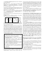
Example: Let X1 be a comparison operation (A = B). Then X1
can be transformed to the following trees X2:
¬
=
=
=
-
0
A
A
⊕ (xor)
0
B
B
A
B
<>
Α
Β
Of course there exist further trees into which X1 can be transformed, e.g. commutativity can be exploited by exchanging the
sons of a commutative operator.
Allocation: In the following the allocation of a simple instruction is described. In contrast to most previous retargetable compilers, allocation and application of transformation rules can be
done concurrently within a CLP system. Therefore a variable,
representing a simple instruction which has to be allocated in
the circuit, is constrained to a set of alternative trees. Allocation
starts at the destination (e.g. the left hand side of an assignment) and from there a recursive search backward through the
circuit is performed as follows:
allocate(statement tree, destination)
The predecessor RT component of the destination is determined and the following cases are distinguished:
a) The statement tree can be mapped to the predecessor
behavior tree: success
b) The predecessor is a register or memory: insert a new
control step and use the predecessor as temporary cell;
call allocate(statement tree, predecessor)
c) A subtree including the root of the statement tree can be
mapped to the predecessor behavior tree: call allocate(‘rest’ of statement tree, predecessor)
d) The output of the predecessor can be switched to an
input (transparent mode): call allocate(statement tree,
predecessor)
e) otherwise: fail
Steps a) and d) allow the application of a transformation rule.
Allocation of constants terminates at components allowed as
constant sources: instruction memory, primary inputs and
decoders. During constant allocation it can be necessary to split
a constant bit string into several substrings, in order to deal
with ports of different bitwidth. This is handled by a concatenation operator. All substrings are sequentially allocated. Final
result of the allocation is a relocatable program and a set of
constraints representing data dependencies, dependencies
between addresses etc.
Since the complete description of the exploitation of constraints would exceed the size of this paper, we have used the
concurrent application of transformation rules during allocation to present advantages of CLP languages.
5.2.2 SCHEDULING, COMPACTION, BINDING
After code generation, a relocatable program consisting of a set
of instructions and a set of partially ordered labels is given.
Therefore, three tasks have to be done: A program has to be
scheduled, linked and optionally compacted. Every label has to
be bound to a number within the address range of the instruction memory and a total order of the labels and the corresponding instructions has to be found. Relocatable code is mapped to
absolute code. Instructions which can be executed in parallel
can be compacted, i.e. two or more instructions are merged to
one instruction.
We perform global scheduling while concurrently compacting
and binding the code. Here we make extensive use of linear
constraints over the integer domain. In this way it is possible to
exploit the parallelism of the target processor. Global scheduling is possible because of the specific structure of the basic
blocks of self-test programs, mainly consisting of move, comparison and conditional jump instructions. A (simplified) formal description of the scheduling, compaction and binding
phase follows. First we distinguish between absolute code and
relocatable code. Thereafter, we define what kind of constraints
are allowed to represent dependencies between variables and
labels. Next we define necessary preconditions to merge two
instructions. An example illustrates how instructions are
merged together. Let Start, Address, End and n be natural
numbers. Start ≤ Address ≤ End, is the address range of the
instruction memory and n its width.
Def. 3: Let L be a set of labels and V be a set of variables. Relocatable code RC is a tuple RC = (P, C) with P = {(Li, Ii) | Li∈L,
Ii ∈ {{0,1,X}∪ V}n} and C is a set of linear constraints over
L∪V.
The set V is used to represent dependencies between the
instructions and the labels. For instance jump addresses usually
are coded within the instructions and every variable Vi ∈ V
finally represents a binary number.
Def. 4: Absolute code AC is a set of tuples AC = { (Li, Ii) |
Start ≤ Li ≤ End, Ii ∈ {0,1,X}n}, i.e. Li is a bound label and Ii
is the corresponding instruction.
Let P(I, k) be the projection of a bit string on the k-th bit (highbit on the left of a bit string, low-bit on the right of a bit string.
The rightmost bit position is 0).
Def. 5: Assumed Ii, Ij ∈ {{0, 1, X}∪ V}n are relocatable
instructions. The predicate compatible(Ii, Ij) is true iff ∀k, 0 ≤
k ≤ n-1:
(P(Ii,k) = P(Ij,k)) ∨ (P(Ii,k) = X) ∨ (P(Ij,k) = X) ∨
(P(Ii,k) ∈ V ∧ P(Ij,k) ∉ V) ∨ (P(Ij,k) ∈ V ∧ P(Ii,k) ∉ V)
If compatible(Ii,Ij) is true, we say Ii and Ij are compatible.
Instructions which are compatible are candidates to be compacted. With above formalism, scheduling, compaction and
binding is reduced to the problem of solving a system of linear
equations and inequalities.
Example: Consider the following relocatable program RC:
RC = ({(L1, (1,0,X,1 ,1, 0,0,1 ,1, X)),
(L2, (0, X,A,B,D, 0,0,1, 0, X)),
(L3, (1, 1,X, 0,1, 0,1 ,1, X, X)),
(L4, (1, X,X, 0,1, 0,X ,1, 1, 0)) },
{L1 ≤ L2, L2 ≤ L3, L3 ≤ L4, L1 + 2 = L2, L1 = 4,
D + 2*B + 4*A=L1, 0≤A, A≤1, 0≤B, B≤1, 0≤D, D≤1 })
RC can be mapped to the absolute code AC:
compactible(I3, I4) is true =>
AC = {
(4, (1,0,X,1,1,0,0,1,1,X)),
(6, (0,X,1,0,0,0,0,1,0,X)),
(7, (1,1,X,0,1,0,1,1,1,0)) }
The set of constraints C has been resolved:
L1 = 4, L2 = 6, L3 = L4 = 7, A = 1, B = 0, D = 0
Above formalism is flexible and powerful enough to handle
complicated address restrictions. Linear constraints are general
enough to express strange address generation schemes (even
the ones described in [3]).
Additionally we can specify a program start address and a program counter initialization value as linear constraints. Data
dependencies, address relations and relative jumps are specified as linear constraints. To achieve a sequence of instructions,
consecutive labels of instructions normally must have a distance of 1 to exploit the increment operator of the program
counter, constraints like Li+1 - Li ≤ 1 can be declared. But this
is not necessary, it depends on the given circuit.
Assume, a relocatable program RP = (P,C) with the set of labels
L is given where the start instruction of P is (Ls, Is) with Ls ∈
L is a special label and Is is the corresponding relocatable
instruction. RP is easily linked to a constant program start
address A0 by just extending the set of constraints C with the
constraint Ls = A0, i.e. the new set of constraints is C’ = C ∪
{Ls=A0}.
A program counter initialization value can be considered by
extending the set of labels with a label L0, i.e. the new set of
labels is L’ = L ∪ {L0}. Additionally an unconditional jump
from L0 to Ls has to be generated. This can be done by extending the set of constraints C’ with the constraint L0 + D = Ls, i.e.
the new set of constraints is C” = C’ ∪ {L0 + D = Ls} with Start
≤ D ≤ End and D is the (jump) distance between the two
addresses L0 and Ls: D = Ls - L0.
Scheduling, compaction and binding can be handled concur-
rently and with a minimum of programming effort (the complete scheduling, compaction and binding phase has about 200
lines of code!) using the built-in constraint solving mechanism
for the integer domain and the Prolog inherent backtracking
mechanism.
6. RESULTS
A retargetable compiler for self-test programs (6500 lines of
code) has been fully implemented in the constraint logic programming language ECLIPSE [10]. Supporting tools are: an
event driven bidirectional RT simulator (5800 lines of code)
and a circuit analyser (2217 lines of code). Half of these lines
of code are comments and so CLP programs are pretty short
compared to imperative implementations (ratio ~ 1:4). We
applied the system to a variety of digital processors to show the
efficiency of the new techniques. The results shown here indicate that an implementation with CLP can be applied to realistic structures.
Table 1 describes the example circuits: the general purpose
microprocessors simplecpu [6], demo [20] and mano [19];
prips [1] is a coprocessor with a RISC-like instruction set,
which provides data types and instructions supporting the execution of Prolog programs. The number of RTL components,
the width of the datapath and the width of the microinstruction
controller is given.
Depending on the complexity of the processor the measured
time for the circuit analysis phase ranges from 0.5 seconds up
to two minutes for complex architectures.
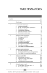
Table 2 shows the results for the retargetable self-test program
compiler. The number of compiled TCL instructions (note,
even a memory test loop is only one TCL instruction), the
number of generated instructions (#µI), the number of generated stimuli patterns, CPU time in seconds and the ratio (generated instructions per second) is given. All times are measured
on a SPARC 20 workstation. The results for code generation
without compaction and the results for programs which have
been compacted are given. It can be seen, that the CPU times
for both cases are very similar because a) the compaction is
done very fast and b) the saved time is consumed by the output
handling of more instructions.
Table 1: Example Processors Circuit Information
circuit
RTL modules
instruction memory width
datapath width
simplecpu
10
20
4
demo
16
84
16
prips
50
83
32
mano
21
50
16
These TCL programs just serve to demonstrate the compilation
speed but by no means constitute complete test sets. All compiled programs have been validated with the above mentioned
simulator. A small number of primary input stimuli patterns
indicates, that the processor is mainly able to test itself,
whereas a large amount of stimuli patterns indicates that certain
constants can not be allocated within the circuit. Compaction of
self-test programs only results in 10% - 20% less code because
test programs usually are not highly parallel.
Table 2: RESTART Compilation Results
circuit
# TCL
uncompacted
#
stimuli
#µI
sec #µI/sec
compacted
#µI
sec #µI/sec
simplecpu
7
5
11
0.71
15.5
11
0.71
15.5
demo
16
75
105
26.7
3.93
93
26.2
3.55
demo
17
73
102
26.1
3.9
91
26.46
3.4
mano
12
1
74
14.81
5
58
14.26
4
mano
15
1
136 37.41
3.63
113
36.5
3.1
prips
7
0
17
0.84
17
20.5
0.83
20.2
One of the 16 TCL instructions of program 1 of the demo CPU
is a test loop for detecting faults in the instruction decoding and
control function of the 16 bit ALU (the ALU has two 16-bit
data inputs a and b and a 3-bit control input ctr selects one of 8
ALU functions) as follows:
FOR ctr := 0 TO 7 DO TEST ALU(#5555,#FFFF,ctr);
Above test loop has been compiled by RESTART and the
resulting self-test program has been stored as initialization for
the microinstruction memory. Now we slightly modified the
hardware description of the ALU, i.e. we modified the instruction decoding and control function of the ALU resulting in a
“faulty” ALU. The rest of the processor has been left
unchanged. An RT simulation of the “faulty” processor
together with the self-test program has been performed and of
course all the injected faults have been detected.
7. CONCLUSIONS
We have shown that test programs for embedded processors
can be automatically generated. The generation process essentially consists of matching a test code specification against a
structural description of the processor. For the first time, this
process has been viewed as a special case of retargetable code
generation. It has been possible to compile self-test programs
for several processors.
Furthermore, we have shown how the built-in support for symbolic variables and constraints over these can lead to a more
efficient software production process. Several subproblems can
be handled concurrently e.g. coupling of the code generation
phases: code selection, resource allocation and scheduling. It is
well known that the consideration of all relevant design constraints is a key issue in CAD. CLP languages have built-in
mechanisms for such constraints and we have successfully
exploited the potential that is inherent in one of these languages.
REFERENCES
[1] C. Albrecht, S. Bashford, P. Marwedel, A. Neumann, W. Schenk. The
design of the PRIPS Microprocessor, 4th EUROCHIP-Workshop on VLSI
Training, 1993.
[2] A. Alomary, T. Nakata, Y. Honma, M. Imai, N. Hikichi. An ASIP instruction set optimization algorithm with functional module sharing constraint.
Int. Conf. on Computer-Aided Design (ICCAD), pp. 526-532, 1993.
[3] T. Baba, H. Hagiwara. The MPG System: A Machine-Independent efficient microprogram generator. IEEE Trans. on Computers, Vol. C-30, pp.
373-395, 1981.
[4] R. Beckmann, U. Bieker, I. Markhof. Application of Constraint Logic Programming for VLSI CAD Tools. Constraints in Computational Logic,
First Int. Conf., Munich, 1994.
[5] F. Benhamou, A. Colmerauer (editors). Constraint Logic Programming:
Selected Research. Cambridge, MA: MIT Press, 1993
[6] U. Bieker, A. Neumann. Using logic programming and coroutining for
electronic CAD. 2nd Int. Conf. on the Practical Applications of Prolog,
London, April 1994.
[7] D. Brahme, J. A. Abraham. Functional Testing of Microprocessors. IEEE
Transactions on Computers, Vol. C-33, No. 6, 1984.
[8] W. F. Clocksin. Logic Programming and Digital Circuit Analysis. The
Journal of Logic Programming, pp. 59 - 82, March 1987.
[9] CHIP User’s Guide, COSYTEC SA, Parc Club Orsay Universite, 4, rue
Jean Rostand, 91893 Orsay Cedex, France, 1991.
[10] ECLIPSE 3.4 User Manual. ECRC Common Logic Programming System.
ECRC GmbH, Arabellastr. 17, Munich, Germany, 1994.
[11] A. Fauth, A. Knoll. Automated generation of DSP program development
tools using a machine description formalism. Int. Conf. on Audio, Speech
and Signal Processing, 1993.
[12] M. Ganapathi, C.N. Fisher, J.L. Henessy. Retargetable compiler code generation, ACM Computing Surveys, Vol. 14, (4) 1982.
[13] P. W. Horstmann. Automation of the Design for Testability Using Logic
Programming. Dissertation, University of Missouri, 1983.
[14] Design Automation Standards Subcommittee of the IEEE. Draft standard
VHDL language reference manual. IEEE Standards Department, 1992.
[15] G. Krüger. Automatic generation of Self-Test programs - A new feature of
the MIMOLA design system. 23rd Design Automation Conference, 1986.
[16] G. Krüger. A tool for hierarchical test generation. IEEE Trans. on Computer Aided Design of Integrated Circuits and Systems, Vol. 10, April 1991.
[17] J. Lee, J. Patel. An instruction sequence assembling methodology for testing microprocessors. International Test Conference, 1992.
[18] C. Liem, P. Paulin. Flexware - A flexible firmware development environment. Proc. European Design & Test Conference, pp. 31-37, 1994.
[19] M. Morris Mano. Computer System Architecture. Prentice-Hall Int., Inc.,
Third Edition, 1993.
[20] S. Bashford, U. Bieker, B. Harking, R. Leupers, P. Marwedel, A. Neumann, D. Voggenauer. The MIMOLA Language - Version 4.1. Technical
Report, Computer Science Dpt., University of Dortmund, Sept. 1994.
[21] L. Nowak, P. Marwedel. Verification of hardware descriptions by retargetable code generation. 26th Design Automation Conf., pp. 441-447, 1989.
[22] J. V. Praet, G. Goossens, D. Lanneer, H. D. Man. Instruction set definition
and instruction selection for ASIPs. 7.th Int. Symposium on High-Level
Synthesis, 1994.
[23] Prolog III Reference Manual. PrologIA, Parc Technologique de Luminy Case 919, 13288 Marseille Cedex 09, France, 1991.
[24] H. Simonis. Test generation using the constraint logic programming language CHIP. Proc. of the 6th International Conf. on Logic Programming,
Lisboa, Portugal, pp. 101 - 112, June 1989.
[25] D. Svanaes, E. J. Aas. Test generation through logic programming. NorthHolland, INTEGRATION, the VLSI journal, No. 2, 1984.
[26] S. M. Thatte, J. A. Abraham. Test generation for Microprocessors. IEEE
Transactions on Computers, Vol. C-29, No. 6, 1980.
[27] TMS320C2x User’s Guide, Rev. B, Texas Instruments, 1990.
[28] T. Wilson, G. Grewal, B. Halley, D. Banerji. An integrated approach to
retargetable code generation. 7. th Int. High-Level Synthesis Symp., 1994.