1
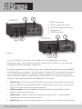
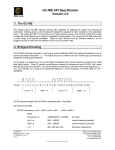
MANUAL
NETKIT-IR/-RS
1
[email protected]
Introduction
The APart Netkit product family is designed to quickly connect almost any electrical
device with RS232 or IR control to a network and comes with a choice of wired
TCP/IP connectivity to infrared (IR) or serial (RS232) equipment. The IR units include
3 configurable in/outs and all units (IR and RS) include built-in IR learning. An
embedded web server allows easy configuration from any web browser. Now it
is possible to design and integrate a low-cost custom control system for APart
products and other devices with serial or infrared control possibilities. The NETKITIR and NETKIT-RS allow easy integration with PC, Mac, iPhone/iPod/iPad and
Android devices via freely available software applications.
This manual describes the various features from our Netkit units. You can use
third party software to operate the Netkits via home control units, tablets or
smartphones. An example is described in chapter 7 of this user manual.
How to get started
Connect a standard RJ45 network cable and the power supply to your Netkit unit.
Connect the other end of the network cable to your wireless router or IP network.
In its default configuration, the Netkit models use DHCP to automatically obtain
an IP address from your network router. To determine the IP address, download
the Netkit Help application from our website. Run the program from a Windows
PC that is connected to the network. The Netkit Help application listens for Netkit
units multicast beacons and displays the Netkit IP address and other details within
one minute. If a DHCP server is not present, defaulted Netkit units will reside at IP
192.168.2.100
Each Netkit unit has an internal IR learner. To use it, download the latest Netkit
Learn application from our website. Once connected to your Netkit Learn program,
simply point your infrared remote at the small hole located to the right of the power
connector (see figure 1) and press any button you want captured by Netkit Learn.
Netkit units’ configuration can be reset to factory defaults by inserting a metal
pin (like a paper clip) into the small opening located to the right of the power
connector (see figure 1). Do not push the paper clip in deeper than approximately
2
WWW.APART-AUDIO.COM
3
NETKIT-IR
1
4
1.
2.
3.
4.
5.
2
figure 1
RJ45 connector
Power supply connector
IR learning eye/reset switch
IR module
RS232 module
3
NETKIT-RS
1
5
2
3 mm. The LED’s on the front of the Netkit unit will rapidly blink in unison,
indicating a reset. Use a light touch when resetting your Netkit unit, as force may
damage your Netkit hardware irreparably.
For easy programming and Netkit setup, four dedicated applications are available
for download on our website. You will need a Windows PC connected to a network
via a router and at least one available network connection on the router. Set the
router to DHCP mode for easy discovery of the Netkit units. With the configuration
tools, you can easily assign fixed IP addresses if necessary.
• Netkit help: this tool searches for Netkit units in your network and allows easy
access, hardware and network specific configuration of the units. Use this tool
first! It will make further programming easier.
• Netkit convert: converts hexadecimal commands to commands in Netkit
specific format and vice versa.
• Netkit learn: capture infrared commands and save them in Netkit specific,
hexadecimal or uncompressed formats.
• Netkit test: test your commands before using them in your specific application.
3
[email protected]
Netkit application programming interface. Version 1.0
1. The Netkit modular design concept
The Netkit product family’s modular design provides a variety of capabilities.
Each module provides a particular function: power and network connections, with
either infrared (IR) or digital connections (RS232). A module may also support
one or more connectors of the same type. For example, an IR module has three
independent IR connectors; whereas, a serial module has only one serial RS232
connector. This is due to the fact that the number of connectors a module can
support is dictated by its 1.5 inch physical width.
It is important to understand that a module’s address is determined solely by its
physical position within the Netkit enclosure. Each module occupies 1.5 inches
of front panel space. At power on, module addresses are assigned starting with
“0” for the left-most module (containing the network and power connectors) and
increasing sequentially to the right until all module addresses are assigned (see
figure). This presents a consistent programming interface as additional modules are
added.
A connector’s address is its position within a module, starting at 1 on the left, and
increasing sequentially as you move to the right. A complete connector address
includes the module address and the connector location in the module, separated
by a colon. One IR module is contained in the Netkit-IR (figure 1). The first IR
connector on the IR module has an address of 1:1, whereas the third IR connector
has an address of 1:3.
IR Connectors: Support for an IR blaster is enabled on the third (*:3) IR connector
on an IR module. This can be configured via command, or must be selected via the
internal webserver. Attempts to configure connectors other than *:3 as an IR blaster
will result in a returned error message. The IR blaster is available on request only.
Contact your local dealer for more information.
4
WWW.APART-AUDIO.COM
2. Configure the IP Address
The TCP/IP connected Netkit unit is set by default to use DHCP to automatically
obtain an IP address from the router. To determine the IP address of a Netkit using
DHCP, run the Netkit Help Utility found on our website. Within 30 seconds of power
up, the Netkit unit will announce its model type, IP address, and MAC ID via a
network wide beacon broadcast, which Netkit Help application displays. The Netkit
unit will also periodically announce its IP address at intervals between 10 and 60
seconds while powered up to maintain up-to-date Netkit Help display information.
The Netkit Help display may be refreshed from the View tab option.
3. Discovery Beacon
The Netkit unit features a beacon message that can assist in locating Netkit units
on the network. The beacon is a UDP packet sent to the multicast IP address
239.255.250.250 on UDP port number 9131. Any system listening to this address
and port will receive the periodic beacon message. The message is sent shortly
after power on and then at random intervals of 10 to 60 seconds thereafter.
The UUID value contains the unique MAC address of the Netkit unit which is also
the name registered with the DHCP server.
4. Command and Data Structure
Communication with the Netkit is accomplished by opening a TCP socket on
Port 4998. All commands and data, with the exception of serial (RS232) data,
are communicated through Port 4998. Port 4998 is used for such things as
Netkit status, IR data, and reading digital input states. All information, with the
exception of serial data, is communicated by comma delimited ASCII text strings
terminated by a carriage return.
Serial data is communicated via Ports 4999 and above.
5
[email protected]
5. Command Set
Commands are initiated by a short ASCII string representing the command type.
Typically, physical address and data information will follow. The structures of Netkit
commands are described in the following sections. Text enclosed in brackets
(<text>) must be substituted by its ASCII definition. Multiple ASCII choices are
divided by separator ( | ) characters.
Note: Commands are case sensitive.
Example:
The network settings are queried with the get_NET command:
get_NET,<connectoraddress>(enter)
where; <connectoraddress> is 0:1 (network module address)
The command ASCII string sent to the Netkit is: get_NET,0:1(enter)
5.1. General Commands
getdevices
This Netkit command is used to determine installed modules and capabilities.
Each module responds with its address and type. This process is completed after
receiving an endlistdevices response.
Sent to Netkit: Getdevices(enter) (query for modules and capabilities)
device
Sent from each Netkit module in response to getdevices:
device,<moduleaddress>,<moduletype> (one sent for each module)
where for Netkit products; <moduleaddress> is |0|1|
<moduletype> is |ETHERNET|3 IR|1 SERIAL|
All modules are included in the response followed by endlistdevices(enter)
The following are the possible Netkit IR responses to a getdevices command.
device,0,0 ETHERNET(enter)device,1,3 IR(enter)endlistdevices(enter) for IP to three
infrared
device,0,0 ETHERNET(enter)device,1,1 SERIAL(enter)endlistdevices(enter) for IP to
one serial
6
WWW.APART-AUDIO.COM
getversion
Sent to Netkit: getversion(enter)
Sent from Netkit in response to getversion: <textversionstring>(enter)
Where: <textversionstring> is the version number ASCII string
Sent to Netkit: getversion,<moduleaddress>(enter)
Where: <moduleaddress> is |0|1|
Sent from Netkit in response to getversion:
version,<moduleaddress>,<textversionstring>(enter)
get_NET
This command will retrieve the current network settings and return a comma
delimited string with the network settings.
Sent to Netkit: get_NET,0:1(enter)
Sent from Netkit in response to get_NET command:
NET,0:1,<configlock>,<ipsettings>,<ipaddress>,<subnet>,<gateway>
Where:
<configlock> |LOCKED|UNLOCKED|
<ipsettings> |DHCP|STATIC|
<ipaddress> is the assigned network IP
<subnet> is the network subnet mask
<gateway> is the default network gateway
unknowncommand
An unknowncommand response will be sent by the Netkit when a command is not
understood. This can happen if, for example, a connector is set up as a digital
input and the command requested is sendir.
Sent from Netkit in response to unknown commands:
unknowncommand, [error code](enter)
Note: Definitions are contained in the Error Codes table in section 5.2 Serial
Connect
Netkit serial communication is bi-directional, RS232 communication. All
communication is 8 data bits and one stop bit.
Parity, hardware flow control, and baud rate are set through the Netkit internal web
page or via configuration command, with baud rate enabled up to 115.2 Kbaud.
All serial data is passed through without interpretation or conversion via an
assigned, unique IP port. The Netkit serial connector is assigned to IP Port 4999.
If a serial connector is not configured correctly, buffer overflows (indicating data
7
[email protected]
loss), or parity errors will occur. Any errors will be captured and presented on the
Serial web page to aid in proper setup. Settings such as Serial Multiconnection
Mode, 7 data bit mode, or 2 stop bit mode are only accessible from the Serial web
page.
5.2. Serial Commands
set_SERIAL
This command allows for configuration of the Netkit serial.
Sent to Netkit: set_SERIAL,1:1,<baudrate>,<flowcontrol>,<parity>(enter)
where: 1:1 is the Netkit serial connector’s address
<baudrate> is |115200|57600|38400|19200|14400|9600|4800|2400|
1200|
<flowcontrol> is |FLOW_HARDWARE|FLOW_NONE|
<parity> is |PARITY_NO|PARITY_ODD|PARITY_EVEN|
Example:
set_SERIAL,1:1,38400,FLOW_HARDWARE,PARITY_NO(enter)
This command string will set the Netkit serial connector to operate at 38400 baud
with hardware flow control and no parity.
get_SERIAL
This command will retrieve the current Netkit serial settings.
get_SERIAL,1:1(enter)
SERIAL
Sent from Netkit in response to set_SERIAL and get_SERIAL.
SERIAL,1:1,<baudrate>,<flowcontrol>,<parity>(enter)
8
WWW.APART-AUDIO.COM
Note: RS232 Multiple Connection Mode
This mode enables four simultaneous TCP sockets to Netkit port 4999. In this
mode, each socket can transmit data out the serial connector on a packet-bypacket basis. Each packet received for port 4999 will be transmitted completely
before another packet (from the same or different socket) is transmitted out
the serial connector. This ensures complete commands can be received and
understood by the serially connected device. The only requirement is for each entire
command(s) to be sent in one TCP packet. All serial data received by the serial
connection is transmitted to all OPEN TCP sockets on port 4999,
allowing each connected application to maintain and update serial device status.
This mode can only be enabled or disabled from the Serial settings web page.
5.3. IR Commands
5.3.1 General IR Commands
set_IR
This command allows configuration of each IR connector to the desired mode
of operation. The possible modes are IR output, sensor input, sensor notify (see
5.3.2), IR blaster, and LED lighting (see 5.3.3). The IR blaster is only supported on
the third IR connector.
Sent to Netkit: set_IR,1:1,<mode>(enter)
where: <mode> is |IR|SENSOR|SENSOR_NOTIFY|IR_BLASTER|LED_LIGHTING|
Example:
set_IR,1:3,LED_LIGHTING(enter)
This will set the third IR connector to LED lighting mode.
get_IR
This command will retrieve the current mode setting for a designated connector.
Sent to Netkit:
get_IR,1:1(enter) for the 1st IR connector
get_IR,1:2(enter) for the 2nd IR connector
get_IR,1:3(enter) for the 3rd IR connector
Sent from Netkit in response to get_IR query:
IR,1:1,<IR|SENSOR|SENSOR_NOTIFY|IR_BLASTER|LED_LIGHTING>(enter)
9
[email protected]
stopir
A stopir command is used to halt IR transmission. Any remaining <repeat>
counts will be discarded. A stopir command sent to a connector configured as
an input will return an error message. An IR transmission halted with the stopir
command will return a stopir response. Furthermore, if an IR command is halted
before its completion by another connection, the originating IR connection and
the connection sending stopir will both receive a stopir response. If stopped, the
originating connection will not receive a completeir response.
Sent to Netkit:
stopir,1:1(enter) to stop the 1st IR connector transmission
stopir,1:2(enter) to stop the 2nd IR connector transmission
stopir,1:3(enter) to stop the 3rd IR connector transmission
Sent from Netkit in response to stopir command:
stopir,<connectoraddress>(enter)
where; <connectoraddress> is as defined in stopir command
A stopir command always returns a stopir response regardless if the connector is
idle or an IR transmission is actually halted. A stopir response means only that the
stopir command was successfully sent to the Netkit, and any transmission has been
halted from the designated <connectoraddress>.
busyIR
A busyIR response occurs when an IR command is received by a connector that
is already sending an IR transmission. If multiple IP connections are present (i.e.
from multiple iPhone users) there is a possibility of an IR transmission not being
transmitted. This occurs when an IR command is sent to the same IR connector
from another IP connection, and will cause a busyIR response.
A busyIR response does not occur if the two IR commands are executed on different
IR connectors.
Sent from Netkit in response to an attempt to interrupt IR transmission by another IP
connection or socket: busyIR,<connectoraddress>,<ID>(enter)
where: <connectoraddress> is the busy connector <ID> is |0|1|2|…|65535|
(ID is specified in sendir command)
Note: The busyIR response is returned to the originator of the unexecuted IR
command. A command to stopir will only return the stopir response. At no time will
a command of stopir return a response of busyIR.
10
WWW.APART-AUDIO.COM
5.3.2 Sensor Notify
Netkit IR connectors can be configured as Sensor Notify. Use of the set_IR
command to enable Sensor Notify status will enable default settings. This will
set the UDP broadcast port to 9132 with a timer of 10 seconds. Configuration
of Sensor Notify parameters (port and timer) must be changed by way of the IR
settings web page. There, both the UDP port and timer settings can be changed
to suit network and software specifications. Sensor notifications are broadcast by
way of UDP packet, sent in timed increments specified by the web configuration (in
seconds), and also sent when a sensor state changes, notifying anything listening
to the specified UDP port by way of an immediate network broadcast. If the timer
value is set to 0, sensor notifications will broadcast only when the sensor state
changes.
Sensor Notify UDP broadcast packet contents are as follows:
sensornotify,<connectoraddress>:<inputstate>(enter)
where: <connectoraddress> is as defined in section 1.
<inputstate> is as defined in 5.3.2
5.3.3 LED Lighting
This connector state allows for pulse width modulated control (at 120Hz) of LED
lighting. Wiring for the 3.5mm connector must be connected so that the Dim
line comes in on the tip, and the Dim Return line is on the base. The necessary
command syntax and parameters for changing the pulse width carried on the
connector are located below:
Sent to Netkit:
set_LED_LIGHTING,<connectoraddress>,<% intensity>,<linear ramp>(enter)
where: <% intensity> is the target percentage light intensity upon completion |1100|
<linear ramp> |0-10| is the rate of change per unit time; 1 being the slowest and
10 being the fastest.
A ramp of 1 will go from 0% to 100% in about 10 seconds, a rate of 10 will take
about 1 second, while a ramp of 0 will change the value instantly.
Sent from Netkit in response to set_LED_LIGHTING:
LED_LIGHTING,<connectoraddress>,<% intensity1>,<% intensity 2>(enter)
where: <% intensity1> |0-100| is the current lighting intensity
<% intensity2> |0-100| is the target lighting intensity upon completion
11
[email protected]
The state of the LED Lighting connector can be polled for its intensity with the
get_LED_LIGHTING command. Note that the LED_LIGHTING response will always
return with two <% intensity> values. If the connector is not currently changing the
lighting intensity, then both <% intensity> levels will be the same value.
Sent to Netkit: get_LED_LIGHTING,<connectoraddress>(enter)
Sent from Netkit in response to get_LED_LIGHTING:
LED_LIGHTING,<connectoraddress>,<% intensity1>,<% intensity 2>(enter)
where: <% intensity1> is the current lighting intensity
<% intensity2> is the target lighting intensity upon completion
5.3.4 Dedicated LED Lighting Modes
Netkit IR units now have two new Dedicated LED Lighting modes, which are the first
Netkit functions using more than one connector in tandem.
In the Single Input LED mode, the second connector is configured as a lighting
control sensor while the third connector is configured as a LED Lighting connector.
When enabled, standard set_LED_LIGHTING commands function properly when
sent to the LED Lighting connector. This works alongside the lighting control sensor,
which monitors the circuit between the tip and the base of the 3.5mm connector.
When a momentary contact is made, the lighting control sensor toggles the lighting
level between on and off.
When held for a long press, the lighting control sensor will dim or elevate the
lighting level for as long as the contact is closed. The long press function toggles
between elevating light levels and dimming them.
In the Dual Input LED Mode, the first two connectors are configured as lighting
control sensors, while the third connector is configured as a LED Lighting connector.
When in this mode, standard set_LED_LIGHTING commands function properly
when sent to the LED Lighting connector. This mode works alongside the lighting
control sensors, which monitor the circuit between the tip and base of each
respective connector. Connector 1 is the down function sensor. When a momentary
contact is made, this sensor turns the LED Lighting connector to 0%. When held for
a long press, the lighting control sensor will dim the lighting level for as long as the
contact is closed or until it reaches 0 percent (%). Connector 2 is
the “up” function sensor. When a momentary contact is made, this sensor turns the
12
WWW.APART-AUDIO.COM
LED Lighting connector to 100 percent. When held for a long press, the lighting
control sensor will elevate the lighting level for as long as the contact is closed, or
until it reaches 100 percent.
5.3.5 IR Structure
An IR, or infrared transmission, is created by sending an IR timing pattern to the
Netkit. This pattern is a collection of <on> and <off> states modulated with a
carrier frequency ( ƒ ) which is present during the <on> state. A carrier frequency
is typically between 35 to 45 KHz with some equipment manufacturers using as
high as 500 KHz. The length of time for an <on> or <off> state is calculated
in units of the carrier frequency period. For example, an <off> value of 24
modulated at 40 KHz produces an <off> state of 600μS, as calculated below.
A period is 1 /ƒ or 1/40000 or .000025 seconds or 25μS, and a value of 24
periods is 600μS
IR timing patterns typically have a long, final <off> value (or rest state) to ensure
the next IR command is interpreted as a separate IR transmission.
5.3.6 Sending IR
Control of IR devices is accomplished through use of the sendir command. Since
IR commands may take up to 100mS to complete, the Netkit provides a completeir
acknowledgment to indicate when it is ready to accept the next IR command for the
connector in use.
Sendir
Sent to Netkit:
sendir,<connectoraddress>,<ID>,<frequency>,<repeat>,<offset>,<on1>,<o
ff1>,<on2>,<off2>,….,<onN>,<offN> (where N is less than 260 or a total of
520 numbers)
where: <connectoraddress> is as defined in section 1.
<ID> is |0|1|2|…|65535| (1) (for the completeir response, see below)
<frequency> is |15000|15001|….|500000| (in hertz)
<repeat> is |1|2|….|50| (2) (the IR command is sent <repeat> times)
<offset> is |1|3|5|….|383| (3) (used if <repeat> is greater than 1, see below)
<on1> is |1|2|…|65635| (4) (number of pulses)
<off1> is |1|2|…|65635| (4) (absence of pulse periods of the carrier frequency)
[email protected]
13
(1) The <ID> is an ASCII number generated by the sender of the sendir command,
which is included later in the completeir command to confirm completion of each
respective sendir transmission.
(2) The <repeat> is the number of times an IR transmission is sent, if it is not
halted early via a stopir or another IR command (see section 5.4). Values above 50
are accepted, but IR commands are sent only the maximum 50 times. In all cases,
the preamble is only sent once (see <offset> below).
(3)An <offset> applies when the <repeat> is greater than 1. For IR commands
that have preambles, an <offset> is employed to avoid repeating the preamble
during repeated IR timing patterns. The <offset> value indicates the location
within the timing pattern to start repeating the IR command as indicated below. The
<offset> will always be an odd value since a timing pattern begins with an <on>
state and must end with an <off> state.
(4) Since IR transmissions ends in an <off> condition, there must be an equal
number of <on> and <off> states. Also, every <on> and <off> state must meet
an 80μS minimum time requirement for the Netkit to work properly.
Example: With a carrier frequency of 48 KHz, the minimum value for <on> and
<off> states is calculated below.
<off> min = <on>min ≥ 80μS * ƒ = 80μS * 48KHz = 3.84
For proper Netkit operation, all <on> and <off> values in the timing pattern must
be 4 or higher.
All of the conditions above must be met for valid sendir commands. When a
variable is missing or outside the accepted range, an unknowncommand will be
sent by the Netkit. As an exercise, the sendir commands below will trigger a Netkit
unknowncommand response.
sendir,5:3,3456,23400,1,1,24,48,24,960(enter) Netkit module 5 does not exist
Response: ERR_0:0,002
sendir,1:2,23333,40000,2,3,24,48,24,48,960(enter) not an equal number of
<on> and <off>
Response: ERR_1:2,010
sendir,1:3,0,40000,2,2,24,48,24,960(enter) <offset> is an even number
Response: ERR_1:3,007
IR compressed format assigns the first 15 unique <on><off> pairs capital letters
(i.e. A,B,C, etc.) to represent them. In the event that a pair is used in many places
inside an IR command, commands can be written with the capital letter in place of
the designated pair without being offset by commas.
14
WWW.APART-AUDIO.COM
Example: The simple IR command
sendir,1:2,2445,40000,1,1,4,5,4,5,8,9,4,5,8,9,8,9(enter)
can be shortened with this feature: (“4,5” is assigned A, and “8,9” is assigned B)
sendir,1:2,2445,40000,1,1,4,5A8,9ABB(enter)
Both commands are syntactically correct, are accepted by the Netkit, and will
transmit an identical IR command.
completeir
All successful sendir commands are acknowledged with a completeir response
from the Netkit after completion of the IR transmission. The completeir response
associates with the sendir command through an <ID>. When utilized, the <ID>s
can provide a unique identifier to determine which IR transmission has completed.
Sent from Netkit in response to successful sendir:
completeir,1:1,<ID>(enter) for the 1st IR connector
completeir,1:2,<ID>(enter) for the 2nd IR connector
completeir,1:3,<ID>(enter) for the 3rd IR connector
where: <ID> is |0|1|2|…|65535| (ID is specified by originating sendir
command)
Example: A few simple IR commands are shown below:
The following will send the IR timing sequence illustrated in figure 4.2a to the 2nd
IR connector on the Netkit shown in Figure 1.
Sent to Netkit: sendir,1:2,2445,40000,1,1,4,5,6,5(enter)
Sent by Netkit in response to sendir: completeir,1:2,2445(enter)
In the next example, the following two IR commands will send the same IR timing
pattern.
Below are two ways to send the same simple IR timing pattern of 24,12,24,960
four times with a preamble of 34,48: sendir,1:2,4444,34500,1,1,34,48,24,12,24
,960,24,12,24,960,24,12,24,960,24,12,24,960(enter)
sendir,1:2,34,34500,4,3,34,48,24,12,24,960(enter)
Acknowledgments for above IR commands are:
completeir,1:2,4444(enter)
completeir,1:2,34(enter)
Although the same command is sent four times by both sendir commands, the
<ID>s are different, and therefore cannot be considered the same command.
The second IR command structure is the recommended method, avoiding long
commands and allowing repetition of the command to be halted if requested.
15
[email protected]
5.3.7 Smooth Continuous IR Commands
A general discussion is necessary to better understand how smooth continuous IR
commands are executed by the Netkit. This desirable feature is utilized for smooth
volume control or repeating an operation without the appearance of choppy
actions. The approach of sending an IR command with very large repeat counts
and stopping it upon request will work, but can lead to undesirable incidents.
Consider the scenario of large repeat count IR command for raising the volume in
a smooth fashion. The command works properly until the connection is broken. A
repeating IR command is sent, volume continuously increases, then the controlling
iPhone is unexpectedly dropped. The volume continues to rise (possibly damaging
equipment) until a stopir command is ultimately received.
The Netkit solution is to limit the repeat count. Hence, to create a smooth IR
operation, the Netkit resets the IR repeat count each time the identical IR command
(from the same IP connection) is resent. This method will not interrupt and restart
the IR command, but reset the IR repeat count back to the original value.
Example: If the IR repeat count is set to 5, and the IR command has transmitted
3 times, receipt of the same command causes the repeat count to be reset back
to 5. This process can continue indefinitely while a volume button is held down to
create a smooth operation. However, at no time can the command repeat more
than 5 times after the button is released or an IP connection is inadvertently lost,
preventing a potentially serious issue.
By selecting an appropriate <repeat> value, the need for a stopir command
is eliminated. In this example the volume continues to increase smoothly by
retransmitting repeated IR commands due to the volume button being pressed. As
long as the next repeated IR command is received before the previous command
finishes, smooth operation is realized. By choosing a low repeat value, the volume
increase will stop when the volume button is released. Also, proper IR operations
happen even with unintended network delays due to traffic or WiFi connectivity. In
this unlikely event, only small hesitations will be experienced during IR operation.
In the event that the identical command is not received before the original
command is finished, the command will be registered as a brand new command,
and is sent as such. The command in question will operate functionally the same,
but delays between commands may be evident when used in this way.
Increasing the <repeat> value will likely eliminate these discrepancies.
16
WWW.APART-AUDIO.COM
5.3.8 IR Learning
Each Netkit unit contains an on-board IR learner, which is located in the small hole
located below and to the right of the power connector. IR Learner Mode is enabled
by implementing the get_IRL command. IR learning mode cannot be activated if the
unit is configured to control LED lighting.
get_IRL
Sent to Netkit:
get_IRL(enter)
Sent from Netkit in response to get_IRL:
IR Learner Enabled(enter)
Once enabled, the Netkit sends an uncompressed Apart-Audio format sendir
command, terminated by a carriage return, through TCP packets via port 4998.
Although the Netkit product family supports up to eight simultaneous connections,
the captured command will only be sent to the connection that initiated learner
mode. Learner mode is disabled when Netkit units receive any command, or
when stop_IRL is sent. If get_IRL is sent to a unit which is configured to control LED
lighting, you will be sent the IR Learner Unavailable response.
Sent from Netkit in response to get_IRL when configured with an LED_LIGHTING
connector:
IR Learner Unavailable(enter)
stop_IRL
Sent to Netkit: stop_IRL(enter)
Sent from Netkit in response to stop_IRL: IR Learner Disabled(enter)
17
[email protected]
6. Error Codes
The chart below provides a list of error messages returned by the Netkit from
port 4998 and the explanation of each message. Messages are returned in the
aforementioned syntax.
Error Message Explanation
ERR_01 Invalid command. Command not found.
ERR_02 Invalid module address (does not exist).
ERR_03 Invalid connector address (does not exist).
ERR_04 Invalid ID value.
ERR_05 Invalid frequency value.
ERR_06 Invalid repeat value.
ERR_07 Invalid offset value.
ERR_08 Invalid pulse count.
ERR_09 Invalid pulse data.
ERR_10 Uneven amount of <on|off> statements.
ERR_11 No carriage return found.
ERR_12 Repeat count exceeded.
ERR_13 IR command sent to input connector.
ERR_14 Blaster command sent to non-blaster connector.
ERR_15 No carriage return before buffer full.
ERR_16 No carriage return.
ERR_17 Bad command syntax.
ERR_18 Sensor command sent to non-input connector.
ERR_19 Repeated IR transmission failure.
ERR_20 Above designated IR <on|off> pair limit.
ERR_21 Symbol odd boundary.
ERR_22 Undefined symbol.
ERR_23 Unknown option.
ERR_24 Invalid baud rate setting.
ERR_25 Invalid flow control setting.
ERR_26 Invalid parity setting.
ERR_27 Settings are locked.
18
WWW.APART-AUDIO.COM
Notes
19
[email protected]
ANY SUGGESTION?
They are well appreciated and eventually rewarded!
Send your ideas or suggestions to
[email protected]
Company names, product names, and names of formats etc. are the trademarks or registered trademarks
of their respective owners.
© 2012 APart-Audio specifications subject to change without notice.
developed by
Audioprof nv
Industriepark Brechtsebaan 8 bus 1
2900 Schoten
Belgium
20
WWW.APART-AUDIO.COM