1
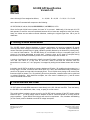
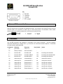
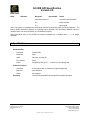
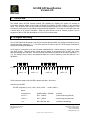
GC-IRE API Specification
Version 2.0
1. The GC-IRE
The Global Caché GC-IRE extends infrared (IR) capability by digitizing IR signals for learning IR
commands, initiating actions, and recording IR signals for playback to other locations in the networked
home. The unique GC-IRE not only works over a wide frequency range, from 32 KHz to 500 KHz, it also
includes the carrier frequency providing a complete IR representation. As a result, the GC-IRE works with
a broad range of IR remote controllers. Other IR input devices, such as Xantech products, can be
plugged into the GC-IRE with the addition of a GC-CXG converter cable.
2. IR Signal Encoding
The GC-IRE transmits IR signals in real time as comma delimited ASCII text strings terminated by one of
several terminator characters ( ⇐ ). The ASCII structure is similar to the GC-100 IR output commands to
simplify IR recording and playback.
An IR signal is a sequence of on and off states modulated with a carrier frequency during the on state
(see figure below). Most IR remote control devices operate at frequencies near 40 KHz, with newer
devices operating up to 500 KHz. On and off states are measured in periods of the carrier frequency (τ =
1/ƒ). For example, an on state of 24 represents 600µs for a carrier frequency of 40 KHz (600 µs = 24 /
40,000Hz).
Period
1
2
3
4
5
<on1> = 4
6
7
8
<off1> = 5
9 10 11 12 13 14 15 16 17 18 19 20
<on2> = 6
<off2> = 5
The IR sequence begins with GC-IRE to identify the data. See below.
Sent from the GC-IRE:
GC-IRE,<frequency>,<on1>,<off1>,<on2>,<off2>,…,<onN>,<offN>⇐
where;
<frequency> is
/32000/33000/…/500000/
(in hertz)
<on1> is
/4/5/…/65635/
(carrier frequency periods)
<off1> is
/4/5/…/65635/
(carrier frequency periods)
⇐ is
0Dh, 0Dh 0Ah, 00h
terminator character(s)
Confidential
Effective: June 27, 2006
PN: 030802-01 ver. 2
1 of 5
11894 Upper Applegate Road
Jacksonville, Oregon 97530
Phone: 541-899-4800
Fax: 541-899-4808
www.globalcache.com
Information subject to change without notice.
GC-IRE API Specification
Version 2.0
The following is an ASCII text string representing a typical IR remote control signal:
GC-IRE,55000,22,340,24,156,23,92,23,157,23,157,23,92,23,156,23,156,23,157,23,157,23,156,
23,157,23,157,23,156,24,156,23,157,23,157,23,1375⇐
The string above is interpreted as a signal with a 55 KHz carrier frequency. The first on state is 22
periods at the carrier frequency or 400µsec. The following off state is 340 periods or 6.182 ms in duration.
The final 1375 off state may actually be longer, but is cut off by the GC-IRE after 25 ms. This is long
enough to distinguish between two separate signals rather than possibly misinterpreting them as one long
signal that would fail to perform their intended functions during playback. Most remote controllers
repeatedly send IR commands when the button is held down. A pause is usually inserted between each
IR command sequence. Sometimes repeated commands differ from the first command. The GC-IRE
encodes repeated commands as separate commands if the pause between the commands is less than
20ms. Otherwise, repeated commands are sent as one long command. The last off state is calculated as
.025ms * ƒ, where ƒ is the carrier frequency in hertz. This guarantees 25ms spacing between IR signals
when played back as output commands.
The format above also allows simultaneous transmission of the ASCII text string during IR input, thus
eliminating undesirable delays in IR commands.
3. IR Signal Compression
Some IR remote controllers send continuous signals without pausing between commands, for example
when holding down the volume control. For low baud rates, this may create a condition where the GCIRE is unable to transmit serial data fast enough to keep the IR commands from overflowing the internal
serial buffer. To avoid this, the GC-IRE employs a compression mode to reduce the serial data to as
much as one third its original size. If a serial overflow does occur, an ASCII X is appended to the end of
the IR text string to indicate the error. The GC-IRE truncates the current IR signal and waits for a quiet
space of 20 ms before transmitting the next IR command.
In this compressed format, repeated on and off pairs are represented in the serial data stream as single
uppercase letters, A, B, C, or D. Up to four different pair combinations are condensed from several ASCII
characters to only one. The compression process assigns A to represent the first on/off pair in a new IR
signal, B to the next different pair, and so on. Using compression, the first occurrence of an on/off pair is
transmitted as before, with all subsequent pair repeats represented by its assigned single letter. To aid
compression, on/off values are consider equivalent if they are within 3 counts of each other reducing
undesirable effects of noise and round-off error. The following example highlights alternating pairs to
ease reading.
GC-IRE,55000,22,340,24,156,23,92,23,157,23,157,23,92,23,156,23,156,23,157,23,157,23,156,
A
B
C
23,310,23,311,23,156,24,156,23,157,23,157,23,1375⇐
D
Confidential
Effective: June 27, 2006
PN: 030802-01 ver. 2
2 of 5
11894 Upper Applegate Road
Jacksonville, Oregon 97530
Phone: 541-899-4800
Fax: 541-899-4808
www.globalcache.com
Information subject to change without notice.
GC-IRE API Specification
Version 2.0
where A through D are assigned as follows,
A = 22,340
B = 24,156
C = 23,92
D = 23,310
as the above IR command will compress to the following:
GC-IRE,55000,22,340,24,156,23,92BBCBBBBB,23,310DBBBB,23,1375⇐
Since the first pair 22,340 never repeats, the letter "A" is not used. Additionally, if the last pair 23,1375
had repeated, it would be sent uncompressed because all four letters are assigned to other pair values.
Lastly, the letters are sent without comma delimiters, reducing the original signal from 138 to just 58
characters.
4. Filtering & Noise Measurement
The GC-IRE contains filtering algorithms to improve performance by removing unwanted IR signals
occurring from direct sunlight or fluorescent lighting. Another source of unwanted signals is caused by
remote controllers operated from too great a distance, partially blocked by an obstruction, pointed poorly,
or in need of fresh batteries. The GC-IRE filtering is not intended to correct a corrupted signal, but to
prevent it from being transmitted as serial data. However, when an IR signal is corrupted during
transmission, the GC-IRE immediately ends the current IR data output with the letter "Z."
A number of techniques are employed to identify incorrect IR signals, including the minimum acceptable
<on> and <off> value of 12. Any time an <on>/<off> value is less than the minimum value the
transmission is not sent, or if it is in progress, it is stopped by ending the serial data stream with the letter
Z.
Included in the GC-IRE is the ability to measure background IR noise. By enabling the noise meter (ny⇐)
through Hyper Terminal, continuous data values (from 0 to 100%) are transmitted serially indicating the
amount of IR signals received within the sample period. This is helpful when placing an IR receiver near
fluorescent lights or plasma TVs. By optimizing IR receiver placement, unwanted noise can be minimized
or avoided completely. With placement complete, the noise meter is disabled (nn⇐), and IR remote
control commands can be sent.
5. Serial Interface and Power
GC-IRE utilizes a female DB9 connector to mate directly to the GC-100 and most PCs. From the factory,
the GC-IRE is set to 9600 baud, 8 bits, 1 stop, no parity, & no flow control.
The serial interface is also the power source for the GC-IRE, which operates off the RTS output voltage
located on pin 7. The RTS voltage must be between 8 and 25 volts and capable of sourcing 5mA for
proper operation. Typical RS232 serial drivers will meet this requirement. Also, hardware handshaking
(or flow control) must be disabled to avoid RTS voltage interruption.
Confidential
Effective: June 27, 2006
PN: 030802-01 ver. 2
3 of 5
11894 Upper Applegate Road
Jacksonville, Oregon 97530
Phone: 541-899-4800
Fax: 541-899-4808
www.globalcache.com
Information subject to change without notice.
GC-IRE API Specification
Version 2.0
6. External IR Sensor Interface
Other IR devices, such as Xantech's IR distribution blocks, can connect to the GC-IRE via the GC-CXG
converter cable. The connection is made using a 3.5mm stereo jack for IR information. Other vendor
sensor output levels must be greater than 3 volts and not exceed 24 volts.
7. Commands
The GC-IRE recognizes and responds to commands via the serial connection. Incorrect character
sequences followed by a carriage return (↵) will result in an unknowncommand response. Commands
are case sensitive and listed below.
Commands
Definition
Response
Non-Volatile
gv↵
get version
ver,x.x.x ⇐
-
-
id↵
identity of device
device,GC-IRE⇐
-
-
tc↵
terminate CR
terminator,CR
Yes
text strings end with 0Dh
tl↵
terminate CR LF
terminator,CR&LF
Yes
text strings end with 0Dh 0Ah
tn↵
terminate null
terminator,NULL
Yes
text strings end with 00h
ny↵
noise meter yes
noisemeterON ⇐
No
noise meter mode on
nn↵
noise meter no
noisemeterOFF ⇐
No
noise meter mode off
e1↵
change IR end
IRend,20msec ⇐
Yes
sets IR end to 20msec
e2↵
change IR end
IRend,35msec ⇐
Yes
sets IR end to 35msec
e3↵
change IR end
IRend,50msec ⇐
Yes
sets IR end to 50msec
e4↵
change IR end
IRend,100msec ⇐
Yes
sets IR end to 100msec
Confidential
Effective: June 27, 2006
PN: 030802-01 ver. 2
4 of 5
Action
11894 Upper Applegate Road
Jacksonville, Oregon 97530
Phone: 541-899-4800
Fax: 541-899-4808
www.globalcache.com
Information subject to change without notice.
GC-IRE API Specification
Version 2.0
Other
Definition
Response
Non-Volatile
Action
-
-
unknowncommand ⇐
-
received invalid command
-
-
X⇐
-
buffer overflow
-
-
Z⇐
-
abort signal
Note: The symbol ⇐ represents the termination character used by the ASCII text string response. The
factory default termination character is a carriage return (Hex 0d). The termination character can be a
carriage return, line feed (Hex 0d 0a) or null character (Hex 00).
Serial commands sent to the GC-IRE are always terminated by a carriage return ( ↵ ) for proper
operation.
8. Specifications
Serial Interface
Connector
Female DB9
Baud rate
9600
Other
No parity, one stop bit
Flow Control
None
Power
Supplied by RTS (pin 7) — must be 8 to 25 volts @ 5mA
IR Sensor interface
Connector
3.5mm stereo jack, 2 conductors, (signal and ground)
Data rate
32 to 500 KHz
Power
Not supplied
Encoding
Comma delimited ASCII text string with termination character.
Confidential
Effective: June 27, 2006
PN: 030802-01 ver. 2
5 of 5
11894 Upper Applegate Road
Jacksonville, Oregon 97530
Phone: 541-899-4800
Fax: 541-899-4808
www.globalcache.com
Information subject to change without notice.