1
YASKAWA
Varispeed G7/F7 OPTION CARD
MECHATROLINK COMMUNICATIONS INTERFACE CARD
USER'S MANUAL
Model: SI-T
YASKAWA
MANUAL NO. SIBP C730600 08A
Copyright © 2004 YASKAWA ELECTRIC CORPORATION
All rights reserved. No part of this publication may be reproduced, stored in a retrieval system,
or transmitted, in any form, or by any means, mechanical, electronic, photocopying, recording,
or otherwise, without the prior written permission of Yaskawa. No patent liability is assumed
with respect to the use of the information contained herein. Moreover, because Yaskawa is constantly striving to improve its high-quality products, the information contained in this manual is
subject to change without notice. Every precaution has been taken in the preparation of this
manual. Nevertheless, Yaskawa assumes no responsibility for errors or omissions. Neither is
any liability assumed for damages resulting from the use of the information contained in this
publication.
Introduction
Thank you for purchasing a Current Vector Control General-purpose Varispeed G7/F7
Inverter and a SI-T MECHATROLINK-I/MECHATROLINK-II Communications Interface
Card (called “SI-T Card” below).
This manual describes the operation and specifications of the SI-T Card, which connects to
the MECHATROLINK-I/MECHATROLINK-II high-speed field network for exchanging
data. Be sure that you have read and understood this manual before attempting to operate the
SI-T Card.
For details on operating the Inverter itself, refer to the Varispeed G7/F7 Series Instruction
Manual (TOE-S616-60.1, TOE-S616-55.1).
Yaskawa Electric, Inc.
General Precautions
• The diagrams in this manual may be indicated without covers or safety shields in order to show
details. Be sure to restore covers or shields before operating the Inverter, and operate the Inverter
according to the instructions provided in this manual.
• The products and specifications described in this manual or the contents and presentation of the
manual may be changed without notice to improve the product and/or the manual.
• When ordering a new copy of the manual due to damage or loss, contact your Yaskawa representative or the nearest Yaskawa sales office and provide the manual number shown on the front
cover.
• Any modifications to the product by the customer invalidate the warranty, and Yaskawa accepts no
responsibility for the results of any modifications
3
Safety Precautions
Carefully read this manual and all other documentation provided with the product before
attempting to install, operate, inspect, or perform maintenance on the product. Within this
manual, safety-related precautions are classified a “warnings” and “cautions.”
WARNING
CAUTION
Indicates precautions that, if not heeded, could possibly result in loss of life or serious injury.
Indicates precautions that, if not heeded, could result in relatively less serious or
minor injury, or damage to the equipment.
Failure to heed even a precaution classified as a caution can result in serious consequences
depending on the situation. All precautions contain important information, so make sure that
they are followed carefully.
IMPORTANT
Indicates important information that the user should make careful note of, even though it is
not classified as a caution.
4
Confirmations upon Delivery
CAUTION
• Never use an Option Card that is damaged or missing components.
Doing so can result in injury.
Installation and Wiring
WARNING
• Never touch the inside of the Inverter with your hands.
Doing so can result in electric shock.
• Before installing or removing the Option Card, or performing wiring operations, always turn OFF the
power to the Inverter and wait until the specified period of time has elapsed after all the Inverter
indicators have turned OFF. (The time is shown on the Inverter’s front cover.)
Failure to do so can result in electric shock.
• Do not allow cables to be damaged, subjected to stress, placed under heavy objects, or pinched.
Doing so can result in electric shock, faulty operation, or damage to the equipment.
CAUTION
• Never touch the Option Card terminals directly with your hands.
Doing so can result in damage from static electricity.
• Insert the connectors securely.
Failure to do so can result in damage or faulty operation of devices.
Settings
CAUTION
• Do not carelessly change the Inverter’s settings.
Doing so can result in damage or faulty operation of devices.
5
Warranty Information
Free Warranty Period and Scope
Warranty Period
This product is warranted for twelve months after being delivered to Yaskawa's customer or
if applicable eighteen months from the date of shipment from Yaskawa's factory, whichever
comes first.
Scope of Warranty
Inspections
Periodic inspections must be conducted by the customer. However, upon request, Yaskawa
or one of Yaskawa's Service Centers can inspect the product for a fee. In this case, if after
conferring with the customer, a Yaskawa product is found to be defective due to Yaskawa
workmanship or materials and the defect occurs during the warranty period, then this fee
will be waived and the problem remedied free of charge.
Repairs
If a Yaskawa product is found to be defective due to Yaskawa workmanship or materials and
the defect occurs during the warranty period, Yaskawa will provide a replacement, repair the
defective product, and provide shipping to and from the site free of charge.
However, if the Yaskawa Authorized Service Center determines that the problem with a
Yaskawa product is not due to defects in Yaskawa's workmanship or materials, then the customer will be responsible for the cost of any necessary repairs. Some problems that are outside the scope of this warranty are:
• Problems due to improper maintenance or handling, carelessness, or other reasons where
the customer is determined to be responsible.
• Problems due to additions or modifications made to a Yaskawa product without
Yaskawa's understanding.
• Problems due to the use of a Yaskawa product under conditions that do not meet the recommended specifications.
• Problems caused by natural disaster or fire.
• Or other problems not due to defects in Yaskawa workmanship or materials.
Warranty service is only applicable within Japan.
However, after-sales service is available for customers outside of Japan for a reasonable fee.
Contact your local Yaskawa representative for more information.
Exceptions
Any inconvenience to the customer or damage to non-Yaskawa products due to Yaskawa's
defective products whether within or outside the warranty period are NOT covered by this
warranty.
6
Restrictions
• The SI-T Card was not designed or manufactured for use in devices or systems that may
directly affect or threaten human lives or health.
• Customers who intend to use the product described in this manual for devices or systems
relating to transportation, health care, space aviation, atomic or electric power, or underwater use must contact their Yaskawa representatives or the nearest Yaskawa sales office
beforehand.
• This product has been manufactured under strict quality-control guidelines. However, if
this product is to be installed in any location where failure of this product could involve
or result in a life-and-death situation or loss of human life or in a facility where failure
may cause a serious accident or physical injury, safety devices must be installed to minimize the likelihood of any accident.
7
CONTENTS
Introduction - - - - - - - - - - - - - - - - - - - - - - - - - - - - - - - - - - - - - - - - - Safety Precautions - - - - - - - - - - - - - - - - - - - - - - - - - - - - - - - - - - - - Warranty Information - - - - - - - - - - - - - - - - - - - - - - - - - - - - - - - - - - - Restrictions - - - - - - - - - - - - - - - - - - - - - - - - - - - - - - - - - - - - - - - - - -
3
4
6
7
1 Overview - - - - - - - - - - - - - - - - - - - - - - - - - - - - - - - - - - - - - 10
2 Checking the Product - - - - - - - - - - - - - - - - - - - - - - - - - - - - 10
2.1 Type and Code No. - - - - - - - - - - - - - - - - - - - - - - - - - - - - - - 10
2.2 Parts List - - - - - - - - - - - - - - - - - - - - - - - - - - - - - - - - - - - - - 11
3 Component Names and Settings - - - - - - - - - - - - - - - - - - - - 11
3.1 Component Names - - - - - - - - - - - - - - - - - - - - - - - - - - - - - - 11
3.2 Communications Connectors - - - - - - - - - - - - - - - - - - - - - - - 12
3.3 LED Indicators - - - - - - - - - - - - - - - - - - - - - - - - - - - - - - - - - 12
3.4 Switch Setting - - - - - - - - - - - - - - - - - - - - - - - - - - - - - - - - - - 13
4 Installation and Wiring - - - - - - - - - - - - - - - - - - - - - - - - - - - 15
4.1 Installing the SI-T Card - - - - - - - - - - - - - - - - - - - - - - - - - - - 15
4.2 MECHATROLINK Communications Cables - - - - - - - - - - - - - 17
5 Transmission Interface - - - - - - - - - - - - - - - - - - - - - - - - - - - 18
5.1 MECHATROLINK-II Cyclic Transmissions - - - - - - - - - - - - - - 18
5.2 Basic Format of Data Transfer - - - - - - - - - - - - - - - - - - - - - - 19
5.3 Communications Phases - - - - - - - - - - - - - - - - - - - - - - - - - - 20
5.4 Application Layer Specifications - - - - - - - - - - - - - - - - - - - - - 21
6 Initial Setup - - - - - - - - - - - - - - - - - - - - - - - - - - - - - - - - - - - 22
7 MECHATROLINK-II Commands - - - - - - - - - - - - - - - - - - - - 23
7.1 Main Commands - - - - - - - - - - - - - - - - - - - - - - - - - - - - - - - - 23
7.2 Sub-commands - - - - - - - - - - - - - - - - - - - - - - - - - - - - - - - - - 37
7.3 Status Details - - - - - - - - - - - - - - - - - - - - - - - - - - - - - - - - - - 42
8 Protective Operations - - - - - - - - - - - - - - - - - - - - - - - - - - - - 44
8.1 Fault Detection Processing - - - - - - - - - - - - - - - - - - - - - - - - - 44
8.2 Alarm Processing - - - - - - - - - - - - - - - - - - - - - - - - - - - - - - - 45
8
9 Specifications - - - - - - - - - - - - - - - - - - - - - - - - - - - - - - - - - - 50
Revision History
9
1
Overview
The SI-T Card is an interface card that connects to the MECHATROLINK-I or
MECHATROLINK-II high-speed field network for communicating with the host controller.
By installing the SI-T Card to a Varispeed G7/F7-series Inverter, various applications are
enabled; monitoring of the run/stop status and the operating conditions as well as the changing
and the referencing of the settings for the Inverter constants from the host controller.
The SI-T Card can be installed in the following Inverters.
• Varispeed G7-series Inverter, software No. 656X.
• Varispeed F7-series Inverter (SPEC:E or later), software No.103X.
Note: “X” indicates the design revision order.
IMPORTANT
2
Varispeed G7/F7 Inverter with an SI-T Card does not conform to CE Marking, although the Varispeed
G7/F7 Inverter itself conforms to CE Marking.
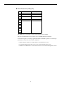
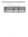
Checking the Product
Check the following items as soon as the product is delivered.
Item
Method
Is there any discrepancy between the shipment and
what was ordered?
Check the type and code No. printed on the center of the
Card. (Refer to 2.1 and 3.1.)
Has the product been damaged in any way?
Inspect the entire exterior of the Card for any damage that
may have occurred during shipping.
Are the contents of the package correct?
Check the contents shown in the following table. (Refer to
2.2.)
Contact your Yaskawa representative immediately if any failure should be found concerning the
above items.
2.1
Type and Code No.
The following shows the type and code No. on the center of the SI-T Card.
Type: SI-T
Code No.: ETC61862X-S016X
Note: “X” indicates the design revision order.
10
3 Component Names and Settings
2.2
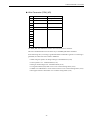
Parts List
The SI-T Card contains the following parts.
Parts Name
3
Qty
SI-T Communications Interface Card
1
Grounding cable (Already mounted on the SI-T Card)
1
Instruction Manual (This manual)
1
Component Names and Settings
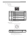
3.1
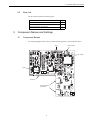
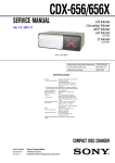
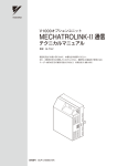
Component Names
The following diagram shows the SI-T Card external appearance and component names.
LED
Rotary switch
DIP switch
Type
Code No.
Communications
connectors
11
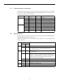
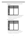
3.2
Communications Connectors
The communications connectors (CN1-1 and CN1-2) connect the SI-T Card to the communications lines of the MECHATROLINK-I or MECHATROLINK-II. The following table
shows the pin numbers and their functions.
Connector
Pin No.
CN1-1
1
(NC)
−
2
SRD−
I/O
Send/receive data (-)
3
SRD+
I/O
Send/receive data (+)
CN1-2
3.3
Signal Name
I/O
Function
Not used.
4
(NC)
−
Not used.
Shell
Shield
−
Not used.
1
(NC)
−
Not used.
2
SRD−
I/O
Send/receive data (-)
3
SRD+
I/O
Send/receive data (+)
4
(NC)
−
Not used.
Shell
Shield
−
Not used.
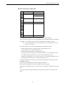
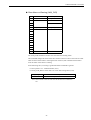
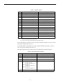
LED Indicators
The LED indicators indicate the status of the communications of the MECHATROLINK-I
or MECHATROLINK-II and the SI-T Card.
However, these indicates are for maintenance checks at Yaskawa. Use the Digital Operator
to check the status.
Name
Display
Explanation
Color
Status
Green
Lit
−
Not lit
Red
Lit
Watchdog timeout error, communications error, diagnosis error, or
resetting hardware
Red
Blinking
ROM check error (once)*, RAM check error (twice)*, DPRAM
check error (3 times)*, communications ASIC self-diagnosis error
(4 times) *, ASIC RAM check error (5 times)*, station address setting error (6 times) *, Inverter model code error (7 times) *
*: Indicates the number of blinking.
−
Not lit
TX
Green
Lit
−
Not lit
RX
Green
Lit
−
Not lit
RUN
ERR
Normal operation
Communications CPU stopped, resetting hardware, RAM check
error, DPRAM check error, station address setting error, or
Inverter model code error
No communications error or self-diagnosis error
Sending data
Sending of data stopped, hardware reset
Searching for receiving carrier
No receiving carrier found, resetting hardware
12
3 Component Names and Settings
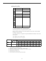
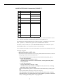
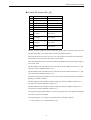
Switch Setting
DIP Switch
The following table shows the SI-T Card DIP switch settings.
1
2
3
4
OFF
Name
Baud rate
Data length
Station
address
Label
Status
S1-1
OFF
4 Mbps (MECHATROLINK-I)*1
ON
10 Mbps (MECHATROLINK-II)
OFF
17-byte data transmission (MECHATROLINK-I/
MECHATROLINK-II)
ON
32-byte data transmission (MECHATROLINK-II)*1
OFF
Set the10’s digit of the station number to 2. Invalid if
the maximum number of units including the S2 of
the rotary switch is 20.
ON
Set the 10’s digit of the station number to 3. Invalid
if the maximum number of units including the S2 of
the rotary switch is 3F.
OFF
Normally OFF*2
ON
Not used.
S1-2
S1-3
Maintenance S1-4
Function
Factory
Setting
ON
ON
OFF
OFF
* 1. Invalid if S1-1 is OFF (4 Mbps) and S1-2 is ON (32-byte data transmission).
* 2. For maintenance. Always leave this switch OFF.
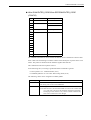
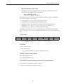
Rotary Switch
The following table shows the SI-T Card rotary switch settings.
F012
34 5
BCD
E
7 8 9A
Label
S2
Status
0 to F
6
3.4
Function
Factory Setting
Set the 1’s digit of the station number: X0H-XFH.
Invalid if the maximum number of units including the
S1-3 is 20 or 3F.
1
Note: Although the range that can be set by S1-3 and S2 is from 20 to 3F,
20 and 3F are invalid (the ERR LED indicator blinks six times).
Therefore, the actual setting range is from 21 to 3E.
Refer to the following section Station-number Setting for details.
13
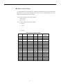
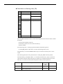
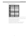
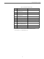
Station-number Setting
A station number is set by both the S1-3 DIP switch and the S2 rotary switch. Station numbers from 21 to 3E are valid. Although 20 or 3F can be set as a station number, do not use
these settings because they will be faulty.
S1-3: Set the 10’s digit of the station number.
OFF = 2 (2X)
ON = 3 (3X)
S2: Set the 1’s digit of the station number.
0 = 0 (X0)
1 = 1 (X1)
x x
x x
F = F (XF)
Switch Setting and Station Number
SI-3
S2
Station
Number
S1-3
S2
Station
Number
OFF
0
Fault
ON
0
30
OFF
1
21
ON
1
31
OFF
2
22
ON
2
32
OFF
3
23
ON
3
33
OFF
4
24
ON
4
34
OFF
5
25
ON
5
35
OFF
6
26
ON
6
36
OFF
7
27
ON
7
37
OFF
8
28
ON
8
38
OFF
9
29
ON
9
39
OFF
A
2A
ON
A
3A
OFF
B
2B
ON
B
3B
OFF
C
2C
ON
C
3C
OFF
D
2D
ON
D
3D
OFF
E
2E
ON
E
3E
OFF
F
2F
ON
F
Fault
14
4 Installation and Wiring
4
Installation and Wiring
WARNING
• Before installing or removing the Option Card, or performing wiring operations, always turn OFF the
power to the Inverter and wait until the specified period of time has elapsed after all the Inverter
indicators have turned OFF. (The time is shown on the Inverter’s front cover.)
Failure to do so can result in electric shock.
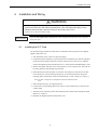
IMPORTANT
4.1
Route the MECHATROLINK communications cables separately from the main circuit wiring and
other power lines.
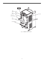
Installing the SI-T Card
Use the following procedure to mount the SI-T Card after removing the Inverter’s Digital
Operator and front cover.
1. Turn OFF the Inverter’s main-circuit power supply.
2. Confirm that all the indicators on the Inverter have turned OFF, wait until the specified
period of time has elapsed (the time is shown on the Inverter’s front cover), and then
remove the Digital Operator and the front cover. Verify that the CHARGE lamp is unlit.
3. Remove the Option Clip (the clip to secure option C or D) on the Inverter. The Clip can
be easily pulled out by pinching its projections.
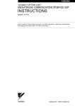
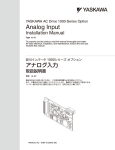
4. Install the SI-T Card on the option C connector 2CN (60 pins) on the Inverter control
board. Secure the Card by inserting the spacers on the control board into the spacer
mounting holes (three holes) of the Card until hearing a “click.” (Refer to A in Fig.1.)
Note: The SI-T Card (option C) and option D cannot be used at the same
time.
5. Insert the Option Clip to its original position.
6. Connect the Card grounding cable to the control circuit terminal E (G) on the Inverter
control board.
7. After the Card is installed, connect the communications cables and set the DIP switches.
(Refer to 3.4 and 4.2.)
8. Remount the Digital Operator and the front cover.
15
Option A
4CN:
Option A connector
2CN:
Option C connector
SI-T Card
Option Clip
(to secure option C or D)
3CN:
Option D connector
A
Control terminal
Fig. 1 Installation of the SI-T Card
16
4 Installation and Wiring
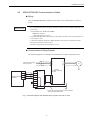
4.2
MECHATROLINK Communications Cables
Wiring
Wire the MECHATROLINK communications cables to the communications connector
(CN2).
IMPORTANT
• For communications cables, use special shielded twisted-pair cables for MECHATROLINK communications.
Recommended cable: JEPMC-W603- *
* is the length (m).
With USB connector with core
• Install MECHATROLINK communications cables apart from main-circuit wiring and other electrical and power lines
• Connect the terminator (model No.: JEPMC-W6022) on the end of the communication lines.
• Maximum transmission distance is 50 m.
• Minimum wiring distance between stations is 0.5 m.
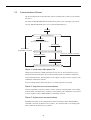
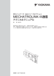
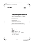
Communications Wiring Example
The following diagram is an example of communications wiring around the Inverters.
R
S
T
3-phase power supply
200 to 230 VAC
NC
NC
SRD-
SRD-
SRD+
MECHATROLINK D SLD
controller
SRD+
U
V
W
Inverter
3-phase, 200 VAC,
0.4 kW
SI-T
SLD
NC
SRDSRD+
SLD
E
E
* If there are noise influences on communication,
remove the grounding cable.
Fig. 2 Connection Diagram with Varispeed G7/F7 (3-phase, 200 VAC, 0.4 kW)
17
M
5
Transmission Interface
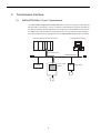
5.1
MECHATROLINK-II Cyclic Transmissions
As a MECHATROLINK-I/MECHATROLINK-II slave, the SI-T exchanges control data and
I/O data with a control device, such as a controller. Communications with the controller are
executed by sending response data timed to the reception of command data for the local station address from the controller in each transmission cycle. The formats for the command
and response data follow the specifications for the MECHATROLINK Inverter commands.
Controller: MP2300 Controller (Example)
PC: SigmaWin (Example)
CPU
Cyclic transmission
MECHATROLINK-II
MP2300IO
SI-T
I/O (Slave)
18
G7/F7 Inverter
(Slave)
SGDS
Servo (Slave)
5 Transmission Interface
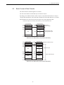
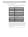
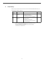
5.2
Basic Format of Data Transfer
The basic format for transferring data is as follows.
The size of the header for a data link layer is fixed at two bytes.
By setting pin 2 on DIP switch S1, either 17 bytes (17-byte data transmission) or 32 bytes
(32-byte data transmission) can be selected as the data size for the data link layer. If 32-byte
data transmission is selected, only the first 29 bytes are used as application data.
* The first 30 bytes are used only when the INV_I/O sub-command is used.
Command data
Response data
+00H Station address
+01H Control code
+02H Command code
+03H
−
+04H
+00H Station address
+01H
Control code
+02H Response code
+03H
Alarm
+04H
Status
+06H
Data
Header of
data link layer
Data link layer data
and application layer
Data
+11H
+12H
+11H
+12H
WDT
EWDT
Basic format of data transfer (17-byte data transmission)
Command data
+00H Station address
+01H Control code
+02H Command code
+03H
−
+04H
Response data
+00H Station address
+01H
Control code
+02H Response code
+03H
Alarm
+04H
Status
Header of data link layer
Application layer
Data
Data
+11H
WDT
+12H Sub-command
−
+13H
+14H
Data
+11H
EWDT
+12H Sub-command
Sub-status
+13H
+14H
Data
+1FH
+1FH
Not used.
+21H
Data in data link layer
Not used.
+21H
Basic format of data transfer (32-byte data transmission)
19
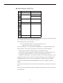
5.3
Communications Phases
The SI-T changes status as described here when a command code or fault is received from
the master.
For details on MECHATROLINK communications phases, refer to the High-speed Field
Network MECHATROLINK System User’s Manual (SIE-S800-26.1).
Power ON
Phase 1 (Initial status)
Connecting
CONNECT command
(Asynchronous communications)
Disconnecting:
DISCONNECT command
Disconnecting:
DISCONNECT command
Phase 2 (Asynchronous communications status)
Connecting: CONNECT command
Set Synchronization
(Synchronous communications)
(SYNC_SET command)
Communications fault
(Watchdog timer fault)
Phase 3 (Synchronous communications status)
Phase 1: Initial status after power ON
Operation proceeds with a default transmission cycle of 2 ms. The transmission cycle is
changed to the time indicated in the synchronous frame when a CONNECT command is
received from the master. Then the phase moves to phase 2 or phase 3 after a response to the
CONNECT command is returned.
Even if a transfer fault is detected in phase 1, no fault notification is provided.
Phase 2: Asynchronous communications
All SI-T commands can be used. Phase 2 starts to count the watchdog timer in the communications frame. The phase moves to phase 3 when a SYNC_SET command is received, and
it moves to phase 1 when a DISCONNECT command is received.
Phase 3: Synchronous communications
Watchdog timer faults in the communications frame are detected. If the DISCONNECT
command is received, the phase moves to phase 1. If a reception fault or a watchdog timer
fault is detected, the phase moves to phase 2.
20
5 Transmission Interface
5.4
Application Layer Specifications
The data format for the application layer conforms to the MECHATROLINK-II link command specifications. The SI-T has the following main commands and sub-commands.
Table 1 Main Commands
Name
Function
NOP
No Operation
PRM_RD
Reads Parameters.
PRM_WR
Writes Parameters.
ID_RD
Reads ID numbers.
CONFIG
RAM Write ENTER_CODE and EEPROM Write
ENTER_CODE
ALM_RD
Reads fault and alarm.
ALM_CLR
Clears fault and alarm.
CONNECT
Connect
DISCONNECT
Disconnect
INV_CTL
Controls Inverter Operation.
SYNC_SET
Starts Synchronous Communications.
Table 2 Sub-commands
Name
Function
NOP
No operation
PRM_RD
Reads Parameters.
PRM_WR
Writes Parameters.
ALM_RD
Reads fault and alarm.
INV_I/O
Controls Inverter I/O.
The main commands are used in both the 17-byte and 32-byte data transmissions for
MECHATROLINK-II and with MECHATROLINK-I. The sub-commands can be used only
when the 32-byte data transmission has been selected by means of pin 2 on DIP switch S1. If
a conflict occurs between a request for a main command and a request for a sub-command,
the request for the main command is processed. If either a main command or a sub-command is already being processed, the command being processed is given priority. If an
INV_CTL main command and an INV_I/O sub-command conflict, the sub-command overwrites the main command.
For details on command formats, refer to Chapter 7 MECHATROLINK-II Commands.
21
6
Initial Setup
Before starting communications between the Inverter and the MECHATROLINK master, set
the following constants as required.
Constant
No.
Name
Description
Factory
Setting
B1-02
Run command
selection
0: Digital Operator
1: Control circuit terminal
2: MEMOBUS communications
3: Communications Option Card (Optional)
1
B1-01
Frequency reference
selection
0: Digital Operator
1: Voltage reference
2: MEMOBUS communications
3: Communications Option Card (Optional)
4: Pulse train reference
1
* To run or stop through the MECHATROLINK communications, set 3 to
B1-02. To set frequency, set 3 to B1-01.
For details, refer to the Varispeed G7/F7 Series Instruction Manual
(TOE-S616-60.1, TOE-S616-55.1).
22
7 MECHATROLINK-II Commands
7
MECHATROLINK-II Commands
7.1
Main Commands
The format of the main commands are as follows.
No Operation (NOP)
Byte
1
Command
Response
NOP
NOP
2
ALARM
3
STATUS
4
5
6
7
8
9
10
11
12
13
14
15
16
WDT
RWDT
Only the ALARM and STATUS fields of the response data can be monitored.
This command can be used in all phases.
23
Read Parameter (PRM_RD)
Byte
1
Command
Response
PRM_RD
PRM_RD
2
ALARM
3
STATUS
4
5
NO
NO
SIZE
SIZE
6
7
8
PARAMETER
9
10
11
12
13
14
15
16
WDT
RWDT
The PRM_RD command is used to read the Inverter's internal constants. For offline parameters, it reads the most recently updated setting values.
This command can be used in all phases.
Note: If the MECHATROLINK-II 32-byte data transmission is used,
PRM_RD can be used only in a sub-command.
In the following cases, a warning (STATUS (WARNING) = 1) is generated and the command is ignored. If a warning is generated, the values that are read are undefined.
• While using the operator to change settings: Command alarm (A.95)
• If received as a main command in 32-byte data transmission: Command alarm (A.95)
• If a register number (NO) fault occurs: User constant setting alarm (A.94)
• If SIZE is an odd number or is not between 2 and 8: User constant setting alarm (A.94)
The register number (NO) is the same as the register number that is set and referenced in
MEMOBUS transfers. Set the lower byte (LSB) before setting the upper byte (MSB).
The SI-T stores the data read for PARAMETER from lower byte (LSB) to upper byte
(MSB).
For SIZE, set the number of bytes to be read as an even numbers. Eight bytes can be specified.
The values for the number (NO) and the size (SIZE) in the response are copies of the values
in the command.
24
7 MECHATROLINK-II Commands
Write Parameter (PRM_WR)
Byte
1
Command
Response
PRM_WR
PRM_WR
2
ALARM
3
STATUS
4
5
NO
NO
7
SIZE
SIZE
8
DATA
DATA
WDT
RWDT
6
9
10
11
12
13
14
15
16
The PRM_WR command is used to write the Inverter's internal constants.
To save the setting value in the Inverter's EEPROM, set the CONFIG_MOD in the CONFIG
command to 1. For details, refer to the section describing the CONFIG command.
Note: If the MECHATROLINK-II 32-byte data transmission is used, PRM_WR can be used
only in a sub-command.
In the following cases, a warning is generated and the command is ignored.
• While using the Operator to change settings: Command alarm (A.95)
• If not in phase 2 or 3: Command alarm (A.95)
• During an undervoltage fault: Command alarm (A.95)
• If received as a main command in 32-byte data transmission: Command alarm (A.95)
• If a register number (NO) fault occurs: User constant setting alarm (A.94)
• If SIZE is an odd number or is not between 2 and 8: User constant setting alarm (A.94)
• Data upper/lower limit fault: User constant setting alarm (A.94)
The register number (NO) is the same as the register number that is set and referenced in
MEMOBUS transfers.
Set the lower byte (LSB) before setting the upper byte (MSB).
Set the values for DATA from lower byte (LSB) to upper byte (MSB).
For SIZE, set the number of bytes to be written as an even number. Eight bytes can be specified.
The values for the NO, SIZE, and DATA in the response are copies of values in the command.
25
Read ID (ID_RD)
Byte
1
Command
Response
ID_RD
ID_RD
2
ALARM
3
STATUS
4
5
DEVICE_CODE
DEVICE_CODE
6
OFFSET
OFFSET
7
SIZE
SIZE
8
ID
9
10
11
12
13
14
15
16
WDT
RWDT
The ID_RD command is used to read the ID number.
The following table shows the applicable DEVICE_CODE.
Because of ID area limitations, no more than eight bytes can be read, so use the OFFSET
and SIZE to specify the range.
The leading ID data that corresponds to the specified OFFSET and returned is shown in the
following table.
Up to eight bytes can be used for SIZE.
This command can be used in all phases.
DEVICE_CODE
ID content*6
OFFSET
00
01
02
03
04
05
06
07
Inverter
Model
00H
C
I
M
R
−
G
7
1
Software
Version
02H
*
08
09
0A 0B 0C 0D 0E
2
7
P
5
*2
*3
*3
*3
S
1
2
3
4
S
5
6
7
8
*4
*4
*4
*4
*4
*5
*5
*5
*5
*5
* 1. The A and U portions of special Inverter models G7A and G7U, as well as the portions showing the structure are represented by spaces.
* 2. Indicates the voltage class. 2: 200-VAC input; 4: 400-VAC input
* 3. Indicates the maximum applicable motor capacity. For 7.5 kW, 7P5 is shown.
* 4. Indicates the SI-T software code.
* 5. Indicates the Inverter software code.
* 6. Inverter models are expressed in ASCII, and end in 00H.
26
0F
7 MECHATROLINK-II Commands
Write RAM ENTER_CODE/Write EEPROM ENTER_CODE
(CONFIG)
Byte
1
Command
Response
CONFIG
CONFIG
2
ALARM
3
STATUS
4
5
CONFIG_MOD
CONFIG_MOD
WDT
RWDT
6
7
8
9
10
11
12
13
14
15
16
The CONFIG command are used to enable the data for which constants have been written.
Error codes such as matching of constants cannot be checked by the responses to this command. They must be checked with the STATUS signal's OPE fault bit.
This command can be used in phases 2 and 3.
In the following cases, a warning is generated and the command is ignored.
• If not in phase 2 or 3: Command alarm (A.95)
• If CONFIG_MOD is not a set value: Data setting alarm (A.94)
The following values can be assigned to CONFIG_MOD.
CONFIG_MOD
Description
0
Write RAM ENTER_CODE
The setting value is not saved in EEPROM.
1
The setting value is saved in EEPROM.
Note: With the G7/F7, the maximum number of writes to non-volatile memory is 100, 000, so do not use the CONFIG command too frequently.
If changing several constants, carry out the CONFIG command only
after all the constants have been changed.
27
Read Alarm or Warning (ALM_RD)
Byte
1
Command
Response
ALM_RD
ALM_RD
2
ALARM
3
STATUS
4
5
ALM_RD_MOD
ALM_RD_MOD
6
ALM_DATA
7
8
9
10
11
12
13
14
15
16
WDT
RWDT
The ALM_RD command is used to read the following information about the status of faults
and alarms.
• Present fault and alarm status list
• Fault history (Alarms are not saved in the history.)
• Details of faults
In the following case, a warning is generated and the command is ignored.
• If ALM_RD_MOD is other than a set value: Data setting alarm (A.94)
The fault history is saved in EEPROM and is kept even when the control power is interrupted.
The following table shows the specifications for ALM_RD_MOD and ALM_DATA.
If the fault history (ALM_RD_MOD = 1) is selected, the fault code (1 byte) is entered in
order of detection from ALM_DATA byte 6, and byte 6 is refreshed with the most recent
fault code. If no fault occurred, 00H is displayed to indicate normal operations.
ALM_RD_MOD
ALM_DATA
Max.
Processing
Time
Constant No.
0
Present fault (byte 6), past fault (byte 7)
0.1 s
U2-01 and U2-02
1
Fault history (Alarms are not retained in the history.)
2 max. (bytes 6 and 7)*
0.1 s
U3-01 and U3-04
28
7 MECHATROLINK-II Commands
Clear Alarm or Warning (ALM_CLR)
Byte
1
Command
Response
ALM_CLR
ALM_CLR
2
ALARM
3
STATUS
4
5
ALM_CLR_MOD
ALM_CLR_MOD
WDT
RWDT
6
7
8
9
10
11
12
13
14
15
16
The ALM_CLR command is used to clear the alarm and warning status.
This command changes the status of the slave station. It does not remove the cause of a fault.
After the cause of the alarm or warning has been removed, this command is then used to
clear the status of the alarm or warning.
In the following cases, a warning is generated and the command is ignored.
• If not in phase 2 or 3: Command alarm (A.95)
• If ALM_CLR_MOD is other than a set value: Data setting alarm (A.94)
ALM_CLR_MOD
0
Description
Clears the status of present faults and alarms.
Note: Inverter alarms cannot be reset while the Inverter RUN command is
ON.
29
MECHATROLINK-II Connection (CONNECT)
Byte
1
Command
Response
CONNECT
CONNECT
2
ALARM
3
STATUS
4
5
VER
VER
6
COM_MOD
COM_MOD
7
COM_TIM
COM_TIM
WDT
RWDT
8
9
10
11
12
13
14
15
16
The CONNECT command is used to set the communications mode and establish a connection. After the connection is established, the phase moves to phase 2 or 3.
If a transfer fault is detected after moving to phase 2 or phase 3, notification is given of the
fault. In phase 1, no notification is given even if a transfer fault is detected.
Set VER (version) to 21H (Ver. 2.1) for MECHATROLINK-II, and to 10H (Ver. 1.0) for
MECHATROLINK-I. This setting must match the switch setting.
The communications mode is set by the COM_MOD. For details on the settings, refer to the
following description.
• MECHATROLINK-II (VER: 21H)
Set the factor of the transmission cycle to COM_TIM (communications time) so that the
setting range satisfies the following formulas.
When the transmission cycle is equal to the communications time (COM_TIM=1):
• 32-byte data transmission
1 [ms] ≤ transmission cycle [ms] ≤ 8 [ms]
If the transmission cycle is set to a fractional value, a warning (data setting alarm:
A.94) is generated.
• 17-byte data transmission
0.5 [ms] ≤ transmission cycle [ms] ≤ 8 [ms]
If the transmission cycle is not set to a multiple of 0.5 ms, such as 0.75, a warning
(data setting alarm: A.94) is generated.
When the transmission cycle is not equal to the communications time (1<COM_TIM ≤
32):
2 [ms] ≤ transmission cycle [ms] × COM_TIM ≤ 100 [ms]
If the transmission cycle is less than 2 ms and is set to a fractional value, a warning
(data setting alarm: A.94) is generated. If the communications cycle is set to a fractional
value, a warning (data setting alarm: A.94) is generated.
30
7 MECHATROLINK-II Commands
• MECHATROLINK-I (VER: 10H)
Set the factor of the 2 ms transmission cycle to COM_TIM (communications time).
The setting range satisfies the following formulas.
2 [ms] ≤ COM_TIM ≤ 64 [ms]
COM_TIM is multiplied by a factor of 2.
In the following cases, a warning is generated and the command is ignored. Commands are
also ignored in phase 2 (with no alarm).
• If COM_MOD is set out of range: Data setting alarm (A.94)
• If COM_TIM is set out of range: Data setting alarm (A.94)
• If SUBCMD is set to 1 in 17-byte data transmission: Data setting alarm (A.94)
• If SUBCMD is set to 1 for Ver. 1.0 (VER: 10H): Data setting alarm (A.94)
• If D6, D5, D4, D3, or D0 is set to 1: Data setting alarm (A.94)
For details on the transmission cycle, communications time, and communications phases,
refer to the High-speed Field Network MECHATROLINK System User’s Manual (SIE-S80026.1).
COM_MOD
D7
D6
D5
D4
SUBCMD
0
0
0
D3
D2
DTMOD
D1
D0
SYNCMOD
0
Note: If D6, D5, D4, or D0 is set to 1, a warning will be generated (data setting alarm: A.94).
SUBCMD
0: Sub-command not used.
1: Sub-command used.
Note: With MECHATROLINK (VER: 10H), SUBCMD is fixed at 0.
DTMOD (Data Transfer Mode)
00: Single data transfer mode
10/11: Data setting alarm (A.94)
SYNCMOD (Synchronous/Asynchronous Communications)
0: Asynchronous communications. Move to phase 2.
1: Synchronous communications. Move to phase 3.
31
Disconnection (DISCONNECT)
Byte
1
Command
Response
DISCONNECT
DISCONNECT
2
ALARM
3
STATUS
4
5
6
7
8
9
10
11
12
13
14
15
16
WDT
RWDT
The DISCONNECT command is used to close the connection and move to phase 1.
After moving to phase 1, no check for transmission faults is executed.
This command can be used in phases 2 and 3.
If this command is received while in phase 2 or 3, the data for the control command to the
Inverter is cleared to 0, and a fault reset command is carried out for the Inverter.
32
7 MECHATROLINK-II Commands
Inverter Control (INV_CTL)
Byte
1
Command
Response
INV_CTL
INV_CTL
2
3
ALARM
Operation signals
STATUS
Speed reference
Output frequency
Torque reference
(torque limit)
Output current
8
9
SEL REF1/2
SEL REF1/2
10
SEL MON1/2
SEL MON1/2
11
Reference selected by
SEL REF1
Monitor selected by
SEL MON1
Reference selected by
SEL REF2
Monitor selected by
SEL MON2
WDT
RWDT
4
5
6
7
12
13
14
15
16
The INV_CTL command is used to set the Inverter's operation signals, speed references, and
so on.
These bytes do not need to be set every scan. The settings are saved in the Inverter until the
next data is received or until the power is turned OFF.
For details on operation signals, refer to the following table.
The speed reference unit can be selected with o1-03.
The torque reference is used for both positive and negative values, in units of 0.1%.
The output current can be set to units of 0.1 A or Inverter rated current/8192.
33
Table 3 Operation Signals
Bit
Description
Remarks
0
Forward operation
1
Reverse operation
2
INV multi-function terminal input 3
Default: External fault (EF3)
3
INV multi-function terminal input 4
Default: Fault reset
4
INV multi-function terminal input 5
Default: Multi-step speed reference 1
5
INV multi-function terminal input 6
Default: Multi-step speed reference 2
6
INV multi-function terminal input 7
Default: Jog command
7
INV multi-function terminal input 8 (G7)
Default: External baseblock
8
External fault (EFO)
9
Fault reset*1*2
A
INV multi-function terminal input 9 (G7)
B
INV multi-function terminal input 10 (G7) Default: Multi-step speed reference 4
C
INV multi-function terminal input 11 (G7) Default: Accel/Decel time 1
D
INV multi-function terminal input 12 (G7) Default: Emergency stop
E
Fault history trace clear
F
External BB command
Default: Multi-step speed reference 3
* 1. Check that the faults has been successfully reset by confirming that the
STATUS (RESET) bit has turned OFF.
* 2. Errors are not reported while the fault reset signal is ON.
Use the SEL REF1/2 command to select the contents of REF1 with bits 0 to 3 and to select
the contents of REF2 with bits 4 to 7.
Use the SEL MON1/2 command to select the contents of MON1 with bits 0 to 3 and to
select the contents of MON2 with bits 4 to 7.
The following tables show the selection ranges for SEL REF1/2 and SEL MON1/2.
Table 4 SEL REF1/2 Selection Range
REF1/2
Item
0
Nothing selected
1
Torque compensation 0.1 %
2
INV analog terminal FM output
3
INV analog terminal AM output
4
INV terminal output:
Bit 0: Terminals M1-M2
(Enabled when H2-01 = F)
Bit 1: Terminal P1
(Enabled when H2-02 = F)
Bit 2: Terminal P2
(Enabled when H2-03 = F)
5 to F
Not used.
Remarks
The SI-T ignores the written data.
34
7 MECHATROLINK-II Commands
Table 5 SEL MON1/2 Selection Range
MON1/2
Item
Remarks
0
Nothing selected.
1
Output frequency
According to o1-03.
2
Torque reference (U1-09): 0.1 %
3
Detected speed from PG counter.
4
Frequency reference (U-01)
According to o1-03.
5
INV analog input A2 0.1 %.
6
Main circuit current voltage: 1 V
7
Inverter alarm
Refer to the Inverter alarm code list.
8
Inverter warning
Refer to the Inverter warning code list.
9
Not used.
A
INV analog input A3 0.1 %.
B
INV terminal DI input
Bits 0 to 7: Terminals S1 to S8
C
INV analog input S1: 0.1 %
D
PG counter
E, F
Not used.
Always 0.
In the following case, a warning is generated and the command is ignored.
• If not in phase 2 or 3: Command fault (A.95)
35
Start Synchronous Communications (SYNC_SET)
Byte
1
Command
Response
SYNC_SET
SYNC_SET
2
ALARM
3
STATUS
4
5
6
7
8
9
10
11
12
13
14
15
16
WDT
RWDT
The SYNC_SET command is used to request the start of synchronous communications.
After this command is issued, synchronous communications are carried out. If communications become asynchronous due to any fault such as a communications fault, this command
can be used to restore synchronous communications.
In the following case, a warning is generated and the command is ignored.
• If not in phase 2 or 3: Command fault (A.95)
36
7 MECHATROLINK-II Commands
7.2
Sub-commands
The format of sub-commands are as follows. Sub-commands can be used only with
MECHATROLINK-II when the 32-byte data transmission has been selected by a switch.
No Operation (NOP)
Byte
17
Command
Response
NOP
NOP
18
SUBSTATUS
19
20
21
22
23
24
25
26
27
28
29
This is the format of No Operation sub-command.
37
Read Parameter (PRM_RD)
Byte
17
Command
Response
PRM_RD
PRM_RD
18
19
SUBSTATUS
NO
NO
SIZE
SIZE
20
21
22
PARAMETER
23
24
25
26
27
28
29
The PRM_RD sub-command is used to read internal Inverter constants.
This sub-command functions in the same way as the PRM_RD main command.
In the following cases, a warning is generated and the command is ignored. If a warning is
generated, the values that were read are undefined.
• While using the operator to change settings: Command alarm (A.95)
• If a register number (NO) fault occurs: User constant setting alarm (A.94)
• If SIZE is an odd number or is not between 2 and 8: User constant setting alarm (A.94)
38
7 MECHATROLINK-II Commands
Write Parameter (PRM_WR)
Byte
17
Command
Response
PRM_WR
PRM_WR
18
19
SUBSTATUS
NO
NO
21
SIZE
SIZE
22
PARAMETER
PARAMETER
20
23
24
25
26
27
28
29
The PRM_WR sub-command is used to write internal Inverter constants.
This sub-command functions in the same way as the PRM_WR main command.
In the following cases, a warning is generated and the command is ignored. If a warning is
generated, the values that were read are undefined.
• While using the operator to change settings: Command alarm (A.95)
• If not in phase 2 or 3: Command fault (A.95)
• During an undervoltage error: Command alarm (A.95)
• If a register number (NO) fault occurs: User constant setting alarm (A.94)
• If SIZE is an odd number or is not between 2 and 8: User constant setting alarm (A.94)
• Data upper and lower limit fault: User constant setting alarm (A.94)
39
RAM Write ENTER_CODE/EEPROM Write ENTER_CODE
(CONFIG)
Byte
17
Command
Response
CONFIG
CONFIG
18
19
SUBSTATUS
CONFIG_MOD
CONFIG_MOD
20
21
22
23
24
25
26
27
28
29
The CONFIG command is used to enable data for which constants have been written.
This sub-command functions in the same way as the CONFIG main command.
In the following cases, a warning is generated and the command is ignored.
• If CONFIG_MOD is not set: Data setting value alarm (A.94)
• If not in phase 2 or 3: Command fault (A.95)
Read Alarm (ALM_RD)
Byte
17
Command
Response
ALM_RD
ALM_RD
18
19
SUBSTATUS
ALM_RD_MOD
ALM_RD_MOD
20
ALM_DATA
21
22
23
24
25
26
27
28
29
The ALM_RD sub-command is used to read the fault and alarm status.
This sub-command functions in the same way as the ALM_RD main command.
In the following case, a warning is generated and the command is ignored.
• If ALM_RD_MOD is not set: Data setting alarm (A.94)
40
7 MECHATROLINK-II Commands
Inverter I/O Control (INV_I/O)
Byte
17
Sub-Command
Response
INV_I/O
INV_I/O
18
SUBSTATUS
19
SEL REF3/4
SEL REF3/4
20
SEL REF5/6
SEL REF5/6
21
SEL MON3/4
SEL MON3/4
22
SEL MON5/6
SEL MON5/6
23
Reference selected by
SEL REF3.
Monitor selected by
SEL MON3.
Reference selected by
SEL REF4.
Monitor selected by
SEL MON4.
Reference selected by
SEL REF5.
Monitor selected by
SEL MON5.
Reference selected by
SEL REF6.
Monitor selected by
SEL MON6.
24
25
26
27
28
29
30
The INV_I/O sub-command is used to select the type of output from the Inverter’s external
terminals and refers to the values from the Inverter’s internal monitors.
These settings do not need to be set every scan. The settings are saved in the Inverter until
the next data is received or until the power is turned OFF.
The output from the Inverter’s external terminals is enabled when the multi-function input is
set to not be used.
The SEL REF3/4 sub-command is used to select the contents of REF3 with bits 0 to 3, and
select the contents of REF4 with bits 4 to 7.
The SEL REF5/6 sub-command is used to select the contents of REF5 with bits 0 to 3, and
select the contents of REF6 with bits 4 to 7.
The selection range for SEL REF3 to 6 is the same as that for the SEL REF1/2 command in
the INV_CTL main command.
The SEL MON3/4 sub-command is used to select the contents of MON3 with bits 0 to 3,
and select the contents of MON4 with bits 4 to 7.
The SEL MON5/6 sub-command is used to select the contents of MON5 with bits 0 to 3,
and select the contents of MON6 with bits 4 to 7.
The selection range for SEL MON3 to 6 is the same as that for the SEL MON1/2 command
in the INV_CTL main command.
In the following cases, a warning is generated and the command is ignored.
• If not in phase 2 or 3: Command fault (A.95)
41
7.3
Status Details
This section describes the STATUS field for main commands and the SUBSTATUS field for
sub-commands.
STATUS Field
Bit
0
1
2
3
4
5
Name
ALM
WARNG
CMDRDY
BB OFF
PON
RUNX
Description
Value
0
No alarm
1
Alarm (fault)
0
No warning
1
Warning
0
Busy
1
Ready
Baseblock OFF (OFF when output voltage is being
output from the Inverter or during baseblock.)
0
Baseblock ON
1
Baseblock OFF
Main power supply ON (OFF during undervoltage)
0
Main power supply OFF
1
Main power supply ON
Alarm status
Warning status
Command ready
0
Running
1
6
7
8
0SP
REV
RESET
AGREE
Zero speed
Reverse RUN
1
Zero speed
0
Forward RUN
1
Reverse RUN
0
Fault reset signal input
INV_READY
C
D
E
OPE
UV_R
REMOTE
−
Speed agreement
0
Inverter ready
1
B
Fault reset signal input
0
Speed agreement
1
A
Running
0
1
9
Setting
Inverter ready
0
OPE fault
1
OPE fault
Recovery after power loss or recovery after momentary power loss
0
Recovery after power loss
1
Recovery after momentary
power loss
Local or Remote
0
Local
1
Remote (Transfer)
0
Not used.
1
F
−
0
Not used.
1
* With the MEM_RD command, only the settings for the STATUS (CMDRDY) is valid. Other
bits are not used.
42
7 MECHATROLINK-II Commands
SUBSTATUS Field
18th Byte
D7
D6
D5
D4
D3
−
−
−
−
−
Bit
Name
D0
SUBALM
D1
D2
SUBWARNG
D2
D1
SUBCMDRDY SUBWARNG
Description
Sub-command alarm
Sub-command warning
SUBCMDRDY Sub-command ready
(Sub-command can be received.)
Value
SUBALM
Setting
0
No alarm
1
Alarm
0
No warning
1
Warning
0
Busy
1
Ready
Note: D3 to D7 are not used. A value of 0 is always returned.
43
D0
8
Protective Operations
8.1
Fault Detection Processing
Faults can be detected by two methods: Inverter fault detection and SI-T fault detection.
The SI-T is notified of Inverter faults by the internal interface, and the SI-T sends the
response data, ALARM or STATUS.
The SI-T notifies Inverter of SI-T faults by the internal interface, and the faults are simultaneously sent the response data, ALARM or STATUS.
The following four types of faults can be detected. The subsequent operation varies depending on the type of fault.
Fault Type
Alarm
Warning
Description
Location
Inverter alarm
Major fault that causes damage to the Inverter or machinery
Inverter
Communications alarm
Interference related to MECHATROLINK-II communications
SI-T
Inverter warning
Illegal operation or minor fault not posing any immediate danger
Inverter
Communications warning
MECHATROLINK-II communications fault warning
SI-T
Fault Type
SI-T Processing
MECHATROLINK Response LED2
Status
ALARM
STATUS
WARNG
ALM
Processing
Direction of
Communications
Reset
Inverter alarm
CODE
−
1
−
No special processing
←
Required
Communications alarm
CODE
−
1
Lit
Notification to Inverter
c→
←d
Required
Inverter warning
CODE
1
−
−
No special processing
←
Required
Communications
warning
CODE
1
−
−
No special processing
None
Not required
Note: The meanings of each symbol are as follows.
−: No change
→: Fault notification to Inverter
←: Fault notification from Inverter
When consecutive alarms occur, the SI-T provides notification of the most recent alarm with
a MECHATROLINK response data. If warnings occur simultaneously, notification priority
is given to the warning with the lowest warning code. If alarms and warnings are mixed
together, the SI-T gives notification priority to alarms.
The following table shows the response data when consecutive alarms or warnings occurs.
44
8 Protective Operations
Table 6 Response Data for Consecutive Alarms and/or Warnings
Fault Detection
Previous
Value
Most Recent
Value
Alarm
8.2
MECHATROLINK-II Response Data Contents
Alarm
Alarm
STATUS
WARNG
ALM
Most recent alarm code
0
1
1
Alarm
Warning
Most recent alarm code
1
Warning
Alarm
Most recent alarm code
1
1
Warning
Warning
Warning with the smaller warning code
1
0
Alarm Processing
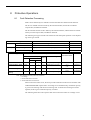
SI-T Communications Fault Detection
The following tables show the communications faults detected by the SI-T and the conditions in which they can be detected.
Table 7 Reception Failures in Each Phase
Communications
Phase
Reception Failure
Transmission cycle
First
Second (Consecutive)
Fault
Phase 1
−
−
−
Phase 2
96
E6
E6
Phase 3
96
E6
E6
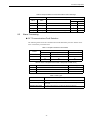
Table 8 Alarm Code (MECHATROLINK-II Response ALARM Value)
ALARM
Description
Fault Type
96
MECHATROLINK-II communications fault warning
Communications warning
E5
MECHATROLINK-II WDT fault
Communications alarm
E6
MECHATROLINK-II communications fault
Communications alarm
Table 9 Fault Types
Fault
Description
Communications failure
Transmission LSI detected a data reception failure.
Transmission cycle fault
A timing fault of a synchronous frame in a transmission cycle was
detected.
Watchdog timer fault
A WDT count fault in a synchronous frame was detected.
45
Other Faults
The following table shows other faults that can be detected by the SI-T.
If a warning occurs, operation will follow the previous command.
ALARM
Description
Fault Type
Operation when Fault Occurs
94
Data setting warning
Communications warning
Received commands are ignored.
95
Command warning
Communications warning
Received commands are ignored.
EC
WDC fault with Inverter
Communications alarm
Waits for power supply to be reset.
ED
Inverter access permission fault
(Access not possible 10 consecutive times)
Communications alarm
Waits for power supply to be reset.
EE
Inverter monitor timer over (1 s elapsed)
Communications alarm
Waits for power supply to be reset.
Received commands are ignored.*
* If the ERR indicator is not lit or flashing, any commands that are received will be ignored.
46
8 Protective Operations
Inverter Fault Notification
If a fault is detected in the Inverter, the SI-T stores the alarm or warning code in the
MECHATROLINK-II ALARM command and simultaneously turns ON the relevant bit in
the STATUS field.
The following table shows the alarm codes for SI-T notification if a fault is detected in the
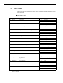
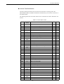
Inverter.
Table 10 Inverter Alarm Codes
ALARM
Operator
Display
01H
PUF
02H
Description
G7
F7
Fuse blown
{
{
UV1
Main circuit undervoltage
{
{
03H
UV2
Control power undervoltage
{
{
04H
UV3
Inrush prevention circuit fault
{
{
06H
GF
Ground fault
{
{
07H
OC
Overcurrent
{
{
08H
OV
Main circuit overvoltage
{
{
09H
OH
Cooling fin overheating
{
{
0AH
OH1
Inverter’s cooling fan stopped
{
{
0BH
OL1
Motor overload
{
{
0CH
OL2
Inverter overload
{
{
0DH
OL3
Overtorque detected 1
{
{
0EH
OL4
Overtorque detected 2
{
{
0FH
RR
Internal braking transistor fault
{
{
10H
RH
Installed braking resistor overheating
{
{
11H
EF3
External fault 3
{
{
12H
EF4
External fault 4
{
{
13H
EF5
External fault 5
{
{
14H
EF6
External fault 6
{
{
15H
EF7
External fault 7
{
{
16H
EF8
External fault 8
{
{
18H
OS
Overspeed
{
{
19H
DEV
Excessive speed deviation
{
{
1AH
PGO
PG disconnection detected
{
{
1BH
PF
Main circuit voltage fault
{
{
1CH
LF
Output open phase
{
{
1DH
OH3
Motor overheating alarm
{
{
1EH
OPR
Digital operator connection fault
{
{
1FH
ERR
Operator error
{
{
20H
OH4
Motor overheating fault
{
{
21H
CE
MEMOBUS communications error
{
{
25H
CF
Control fault
{
{
26H
SVE
Zero-servo fault
{
{
27H
EF0
External fault input from communications option board
{
{
28H
FBL
PID feedback reference lost
{
{
29H
UL3
Undertorque detected 1
{
{
47
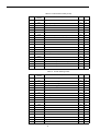
Table 10 Inverter Alarm Codes (cont’d)
ALARM
Operator
Display
2AH
UL4
2BH
Description
G7
F7
Undertorque detected 2
{
{
OL7
High-slip braking OL
{
{
2CH
EF9
External fault 9
{
×
2DH
EF10
External fault 10
{
×
2EH
EF11
External fault 11
{
×
2FH
EF12
External fault 12
{
×
31H
VCF
Main circuit capacitor neutral point potential error
{
×
83H
CPF02
Baseblock circuit error
{
{
84H
CPF03
EEPROM Error
{
{
85H
CPF04
CPU internal A/D converter error
{
{
86H
CPF05
CPU external A/D converter error
{
{
87H
CPF06
Option board connection error
{
{
88H
CPF07
ASIC internal RAM fault
{
{
89H
CPF08
Watchdog timer fault
{
{
8AH
CPF09
CPU-ASIC mutual diagnosis fault
{
{
8BH
CPF10
ASIC version fault
{
{
91H
CPF20
Communications option board A/D converter error
{
{
92H
CPF21
Communications option board self diagnostic error
{
{
93H
CPF22
Communications option board model code error
{
{
94H
CPF23
Communications option board DPRAM error
{
{
G7
F7
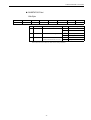
Table 11 Inverter Warning Codes
ALARM
Operator
Display
Description
01H
UV
Main circuit undervoltage
{
{
02H
OV
Main circuit overvoltage
{
{
03H
OH
Cooling fin overheating
{
{
04H
OH2
Inverter overheating pre-alarm
{
{
05H
OL3
Overtorque 1
{
{
06H
OL4
Overtorque 2
{
{
07H
EF
External fault
{
{
08H
BB
Receiving external baseblock command
{
{
09H
EF3
External fault 3
{
{
0AH
EF4
External fault 4
{
{
0BH
EF5
External fault 5
{
{
0CH
EF6
External fault 6
{
{
0DH
EF7
External fault 7
{
{
0EH
EF8
External fault 8
{
{
10H
OS
Overspeed
{
{
11H
DEV
Excessive speed deviation
{
{
12H
PGO
The PG is disconnected
{
{
13H
OPR
Digital operator connection fault
{
{
14H
CE
MEMOBUS communications error
{
{
48
8 Protective Operations
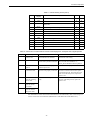
Table 11 Inverter Warning Codes (cont’d)
ALARM
Operator
Display
17H
OL1
18H
Description
G7
F7
Motor overheat
{
{
OL2
Inverter overheat
{
{
1AH
EF0
External fault detected for communications board other
than SI-K2
{
{
1BH
RUNC
Reset during run command input error
{
{
1CH
FBL
PID feedback reference lost
{
{
1DH
CALL
Communications on standby
{
{
1EH
UL3
Undertorque 1
{
{
1FH
UL4
Undertorque 2
{
{
22H
OH3
Motor overheating 1
{
{
23H
EF9
External fault 9
{
×
24H
EF10
External fault 10
{
×
25H
EF11
External fault 11
{
×
26H
EF12
External fault 12
{
×
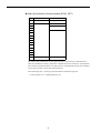
Table 12 Causes and Countermeasures of Main Faults Displayed on Varispeed G7/F7 Digital Operator
Display
Description
BUS
Optional communications error
Communications are not established with the host controller.
Check the LED indicators. Check the communications cable wiring.
SI-T WDT error
There is no continuity in the WDT
for data sent by the host controller.
Execute DISCONNECT or ALM_CLR, and
then use either the CONNECT or
SYNC_SET command to move to phase 3.
External fault from
option
An external fault is being input
from the option card.
Turn OFF the faulty input.
CPF06
Optional
Connection fault
The Inverter and communications
option are not properly connected.
Turn OFF the power to the Inverter and
check the connection between the Option
Card and the Inverter. Then turn the power
back ON. If the fault persists, replace the
Option Card.
CPF21
Communications
optional self-diagnostic fault
The communications option is
faulty.
Turn OFF and back ON the power to the
Inverter. If the fault persists, replace the
Option Card.
CPF22
Communications
optional model
code fault
CPF23
Communications
optional mutualdiagnostic fault
E5
EF0
Cause
Countermeasures
For information on the causes and countermeasures for other faults, refer to the Varispeed
G7/F7 Series Instruction Manual (Manual NO.: TOE-S616-60.1/TOE-S616-55.1).
49
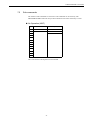
9
Specifications
Item
Requirements
Baud rate
4 Mbps or 10 Mbps*1
Access mode
Start-stop synchronization, master/slave method
Transmission cycle
500 µs to 8 ms*2
Maximum transmission
distance
50 m *5
Data length
17-byte data transmission or 32-byte data transmission*3
Maximum number of
slaves
30 *4 *5
Operating Power Supply
4.75 VDC to 5.25 VDC (supplied from Inverter)
Ambient Temperature
-10°C to 45°C
Humidity
95% max. (with no condensation)
Storage Temperature
-20°C to 60°C
Location
Indoors (free from corrosive gases or dust)
Elevation
1000 m max.
* 1. The baud rate is 4 Mbps for MECHATROLINK-I, and 10 Mbps for
MECHATROLINK-II.
* 2. For MECHATROLINK-I, a cycle is 2 ms. For MECHATROLINK-II, a
cycle is 1 ms to 8 ms for a 32-byte data transmission, and 500 µs to 8
ms for a 17-byte data transmission.
* 3. For MECHATROLINK-I, only a 17-byte data transmission can be
selected.
* 4. The maximum number of connectable stations changes depending on
the types and settings of the host controller, baud rate, or communications cycle. For details, refer to the manuals of your controller.
Communications cycle: Integral multiple of transmission cycles
(depending on the host controller settings).
Example: If the host controller is an MP2300
• For MECHATROLINK-II (32-byte transmission,
2-ms communications cycle):
21 stations max. (21 slaves can be set, but then the maximum number of connectable Inverters will be 16.)
• For MECHATROLINK-II (32-byte transmission,
1-ms communications cycle):
9 stations max.
• For MECHATROLINK-II (17-byte transmission,
1-ms communications cycle):
15 stations max.
• For MECHATROLINK-I: 14 stations max.
* 5. At the maximum transmission distance of 50 m, the maximum number
of slaves is 15.
50
Revision History
The revision dates and numbers of the revised manuals are given on the bottom of the back cover.
MANUAL NO.ޓSIBP C730600 08A
Printed in Japan
April 200604-12
Date of
printing
Date of Printing
December 2004
April 2006
Rev.
No.
−
1
1
Revision number
Date of original
publication
Section
Revised Content
First edition
Back cover
Revision: Address
Varispeed G7/F7 OPTION CARD
MECHATROLINK COMMUNICATIONS INTERFACE CARD
USER'S MANUAL
IRUMA BUSINESS CENTER (SOLUTION CENTER)
480, Kamifujisawa, Iruma, Saitama 358-8555, Japan
Phone 81-4-2962-5696 Fax 81-4-2962-6138
YASKAWA ELECTRIC AMERICA, INC.
2121 Norman Drive South, Waukegan, IL 60085, U.S.A.
Phone 1-847-887-7000 Fax 1-847-887-7370
YASKAWA ELETRICO DO BRASIL COMERCIO LTD.A.
Avenida Fagundes Filho, 620 Bairro Saude-Sao Paulo-SP, Brazil
Phone 55-11-5071-2552 Fax 55-11-5581-8795
CEP: 04304-000
YASKAWA ELECTRIC EUROPE GmbH
Am Kronberger Hang 2, 65824 Schwalbach, Germany
Phone 49-6196-569-300 Fax 49-6196-569-312
YASKAWA ELECTRIC UK LTD.
1 Hunt Hill Orchardton Woods Cumbernauld, G68 9LF, United Kingdom
Phone 44-1236-735000 Fax 44-1236-458182
YASKAWA ELECTRIC KOREA CORPORATION
7F, Doore Bldg. 24, Yeoido-dong, Youngdungpo-Ku, Seoul 150-877, Korea
Phone 82-2-784-7844 Fax 82-2-784-8495
YASKAWA ELECTRIC (SINGAPORE) PTE. LTD.
151 Lorong Chuan, #04-01, New Tech Park 556741, Singapore
Phone 65-6282-3003 Fax 65-6289-3003
YASKAWA ELECTRIC (SHANGHAI) CO., LTD.
No.18 Xizang Zhong Road. Room 1702-1707, Harbour Ring Plaza Shanghai 200001, China
Phone 86-21-5385-2200 Fax 86-21-5385-3299
YASKAWA ELECTRIC (SHANGHAI) CO., LTD. BEIJING OFFICE
Room 1011A, Tower W3 Oriental Plaza, No.1 East Chang An Ave.,
Dong Cheng District, Beijing 100738, China
Phone 86-10-8518-4086 Fax 86-10-8518-4082
YASKAWA ELECTRIC TAIWAN CORPORATION
9F, 16, Nanking E. Rd., Sec. 3, Taipei, Taiwan
Phone 886-2-2502-5003 Fax 886-2-2505-1280
YASKAWA ELECTRIC CORPORATION
YASKAWA
In the event that the end user of this product is to be the military and said product is to be
employed in any weapons systems or the manufacture thereof, the export will fall under
the relevant regulations as stipulated in the Foreign Exchange and Foreign Trade
Regulations. Therefore, be sure to follow all procedures and submit all relevant
documentation according to any and all rules, regulations and laws that may apply.
Specifications are subject to change without notice
for ongoing product modifications and improvements.
© 2004-2006 YASKAWA ELECTRIC CORPORATION. All rights reserved.
MANUAL NO. SIBP C730600 08A
Printed in Japan April 2006 04-12 1 -0
05-7⑦ 04-71014