1
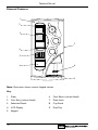
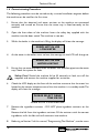
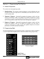
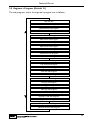
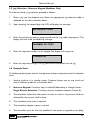
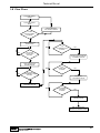
M A N U A L
T E C H N I C A L
Horizon
Part No. PR06743000
Rev A 11/02
Technical Manual
Contents
Page No.
Introduction ...................................................................................................2
Important Safeguards ...................................................................................2
Specification....................................................................................................3
Water Filter - Where Fitted.......................................................................3
External Features ..........................................................................................4
Internal Features ...........................................................................................5
Section 1 - Installation Procedure ............................................................6
Section 2 - Programming The Machine .................................................10
Section 3 - The Vend Cycle ......................................................................30
Section 4 - Technical Information ...........................................................38
Section 5 - Electrical/Electronic Information .......................................41
Section 6 - Figures and Diagrams ...........................................................48
The following symbol is used throughout this Technical Manual:
Safety First! Take care, risk of personal injury.
© Copyright 2002 Crane Merchandising Systems
1
Technical Manual
Introduction
This manual is to be used by authorised personnel involved in installing, commissioning
and servicing the Horizon table-top beverage system. The technical information
contained within this document is for information only and may be changed without
prior notice. Crane Merchandising Systems accepts no responsibility for any damage
caused to the machine through misinterpretation or misuse of the information
contained in this document.
Upon receipt, carefully examine the machine checking for any damage or
missing/incorrect parts. Any discrepancy must be reported to Crane Merchandising
Systems in writing within three working days.
In accordance with the food hygiene regulations and in compliance with local Public
Health Authorities, it is the responsibility of the operator to keep the machine in a
thoroughly clean condition.
Important Safeguards
When installing or servicing the Stentorfield Horizon, always have this manual available
for quick and easy reference and always follow these basic safety precautions:
1.
Ensure that the machine is situated on a strong horizontal surface, at a convenient
height and in a position where it is not likely to be knocked off.
2.
The mains lead should never trail from the machine and should always be kept
away from hot surfaces and sharp edges.
3.
Allow the machine to cool before handling or moving.
4.
Ensure that the mains electricity supply is isolated before removing any of the
protective panels or undertaking any major servicing.Working on live equipment
should only be undertaken when there is no practical alternative.
5.
Never clean or service the brewer unit fitted to freshbrew machines whilst it is
in motion as fingers may become trapped in the mechanism.
6.
When servicing the heater tank be aware that water in the tank can reach a
temperature of approximately 96° C.Water at this temperature can cause severe
burns.
7.
Never immerse the machine in water, or any other liquid.This machine must not
be installed in an area where a water jet may be used. Never use a water jet to
2
Technical Manual
clean this machine.
8.
In normal operating conditions the machine should not freeze-up. In the unlikely
event of the machine freezing, turn off the mains water supply, disconnect the
machine from the mains electricity supply and contact Crane Merchandising
Systems for assistance.
9.
Ensure that you are conversant with the ‘Health and Safety at Work and Electricity
at Work Regulations 1989’.
This machine is for indoor use only and because it is a food machine, should be situated
in a clean, hygienic area.
Specification
Height
Depth
Width
Weight
Electrical Services
(i) Voltage
(ii) Current
(iii) Frequency
Water Services
(i) Pressure
(ii) Stopcock
Base
(i)
(ii)
(iii)
Cabinet (Optional)
Height
Width
Depth
Instant and Freshbrew
870 mm
510 mm
450 mm
60 kg
220 - 240 Volts AC
13 Amp Fused
50 Hz
100 Kpa (1 Bar) - 800 Kpa (8 Bar)
15 mm BSP from rising main
900 mm
770 mm
533 mm
All weights and dimensions are approximate and are for guidance only.
Water Filter - External Fitment (where fitted)
The machine may be fitted with either an Everpure or Brita filter head and filter
cartridge. This unit will be located either within the machines base cabinet (where
applicable) or in the water supply line.
To maintain optimum drink quality, the cartridge should be replaced every six months
or earlier, depending upon the number of vends.
3
Technical Manual
External Features
1
2
STENTORFIELD
3
7
4
5
Horizon
8
6
9
Note: Illustration shows numeric keypad version.
Key:
1.
Door
6.
Coin Return (where fitted)
2.
Coin Entry (where fitted)
7.
Door Lock
3.
Selection Decals
8.
Cup Stand
4.
LCD Display
9.
Drip Tray
5.
Keypad
4
Technical Manual
Internal Features
6
5
7
4
8
9
3
10
11
12
13
2
1
14
Note: Illustration shows freshbrew interior.
Key:
1. Drip Tray
2. Floor Liner
3. Mixing System
4. Large Ingredient Canister
5. Loom
6. Function Switches
7. Small Ingredient Canister
8. Door Switch
9. Coffee Canister (Freshbrew
machines only)
10. Coffee Brewer (Freshbrew machines
only)
11. Dispense Spouts
12. Dispense Head
13. Freshbrew Waste Bucket
14. Drip Tray Grill
5
Technical Manual
Section 1 - Installation Procedure
Important!
It is essential that personnel responsible for installing, commissioning and servicing the
machine understand the following:
1.
The installation and commissioning of the machine should only be carried out by
trained and authorised service engineers.
2.
All water and electrical services must be correctly and safely connected.
3.
All covers should be replaced correctly and securely and the machine left in a safe
condition.
1.1 Installing the Machine
1.
The machine is suitable for indoor use only, sited in an area with a recommended
ambient temperature not below 10º C and not exceeding 30º C.
2.
Prior to moving the machine to its location, ensure that there is sufficient access
space available via passageways, stairs, lifts, etc and that the table/counter where
the machine is to be located is strong enough to safely support its weight. (Refer
to Specifications Table).
3.
The machine should be located near the appropriate water and electrical services
as detailed in the specification table.
4.
To ensure adequate ventilation, 100 - 150 mm (4 - 6 inches) clearance must be
allowed between the back of the cabinet and the wall.
5.
Unlock and open the cabinet door. Remove all transit packing and the installation
kit from the machine. Check for visual signs of damage which may have occurred
during transit.
6.
If the machine is damaged or any parts are missing, you must contact the supplier
immediately.
7.
The machine should be levelled in both front to back and side to side planes using
the four adjustable levelling feet (12 mm thread). Check for correct alignment using
a spirit level placed on the floor of the machine.
6
Technical Manual
Note! Incorrect levelling can result in:
(a) Door misalignment.
(b) Coin acceptance reduction.
1.2 Connecting the Water Supply
1.
The machine should be situated within 1 metre of a drinking water supply from
a rising main, terminating with a W.R.C. approved 15mm compression stop tap.
2.
The water supply should comply with both the Statutory Instrument No.1147 “Water, England and Wales” and The Water Supply (Water Quality) Regulations
1989.Water pressure at the stop tap must be within the limits 1 - 8 Bar (100 Kpa 800 Kpa).
3.
Connect the flexi-hose supplied with the machine to the stop tap ensuring that the
seal supplied is fitted correctly.Flush the system via the stop tap (several gallons) before
connecting the hose to the machine.
4.
Connect the hose to the inlet valve located on the rear of the machine. Ensure that
the seal is correctly fitted. Ensure that all water supply fittings are tight.Turn on the
stop tap and check for leaks.
1.3 Connecting the Electricity Supply
Safety First! THE MACHINE MUST BE EARTHED. ON NO ACCOUNT
SHOULD IT BE EARTHED TO THE WATER SUPPLY PIPE
1.
The machine must be connected to a 240 Volt 50Hz 13 amp fused switched socket
outlet, installed to the latest edition of the IEE regulations, using a 3 pin BS
approved 13 amp fused plug.
2.
Machines are despached from the factory with the input transformer connected
for a 240 volt supply. If the electrical supply differs, the alternative tapping (230
volt or 220 volt) should be used.
Important: If the mains lead becomes damaged in any way it must be replaced by a
special lead available from the manufacturer.
7
Technical Manual
1.4 Commissioning Procedure
The following procedure must be carried out by a trained installation engineer before
the machine can be used for the first time.
1.
Ensure that the electrical and water services to the machine are connected
correctly and turned on. Ensure that the waste tray is fitted correctly to the
machine.
2.
Open the front door of the machine. Insert the safety key supplied with the
machine into the door switch.The machine is now on.
3.
Whilst the boiler in the machine is filling, the display will show the message:
SORRY NOT IN USE
LOW WATER
4.
As the water in the boiler starts to heat, the message on the LCD will change to:
SORRY NOT IN USE
WATER HEATING
5.
Ensure that no water overflows from the boiler tank overflow pipe into the waste
tray. Check the system for leaks.
Safety First! Should the machine fail to fill correctly or leak, turn off the
stopcock and contact the machine supplier for assistance.
6.
Check the LCD display on the front of the machine to ensure that the water has
heated to the correct temperature and that the machine is in standby mode.The
display will show the message:
PLEASE SELECT DRINK
TIME XX:XX
Where XX:XX is the current time.
7.
Remove the ingredient canisters - DO NOT place ingredient canisters on the
floor.
Remove the lids from the ingredient canisters. Fill the canisters with the correct
ingredients, re-fit the lids and re-fit canisters into machine.
8.
8
Referring to Section 2 of this manual,“Programming The Machine”, use the menu
Technical Manual
selections available in the operator’s and engineer’s programs to program the
required settings for correct machine operation.
9.
Press the test vend switch, located in the switch panel mounted above the
ingredient canisters, to check that the machine operates correctly. Place an empty
cup under the dispense head before vending the selection.
10. If the machine is fitted with a coin/card mecahanism, check that the mechanism
and cash box operate correctly.
11. Remove the safety key. Fit the door switch bracket to the door using the two
screws provided. Ensure that the bracket will operate the door switch when the
door is closed. Check for leaks and ensure that the machine is left in a clean and
safe condition.
9
Technical Manual
Section 2 - Programming The Machine
2.1 Modes Of Operation
The machine has three operating modes:
1. Standby Mode - The machine is ready to dispense a vend and displays the time
and type of credit input required. This is followed by the vend cycle and a return
to the standby mode.
2. Operator’s Program - Accessed by pressing the program switch and then
entering the operator’s code via the keypad. This enables the operator to access
sub-programs in order to change information relating to time, drink, price periods
etc. It is not possible to vend a drink from within the operator’s program.
3. Engineer’s Program - Accessed by pressing the program switch and then
entering the engineer’s code via the keypad. The engineer may then access a
number of sub-programs in order to alter the ingredient dispense and machine
parameters or use the machine test facilities.
2.2 Programming Mode
The Stentorfield Horizon may be fitted with either a single button selection keypad or
a numeric keypad. Both keypads perform identical functions during programming.
Numeric Keypad
Single Button
Selection Keypad
10
Technical Manual
To access the programming mode you need to enter a sequence of key strokes on the
keypad.The time between each key stroke must be less than 5 seconds otherwise the
machine will return to standby mode. Once in programming mode there is no time
constraint.
During programming the buttons/keys are used as follows:
0-9
“C”
Blank
▲
Used for data entry
Used for correcting data and entering a higher program level
For moving to a higher program level
For indexing up in a program
Normal
▼
For entering data in a program, or entering a lower program level
For indexing down in a program
Note: To avoid confusion, in this manual the Normal key will be referred to as the
Access key.
2.3 Accessing the Programming Mode
In order to enter the Engineer's or Operator's programs proceed as follows:1.
Press the program entry switch, mounted in the panel located above the ingredient
canisters, followed by the appropriate access code. Code entry errors may be
erased using the cancel (C) key.
2.
With the correct code entered the title of the first sub-program will be displayed
on the LCD. In the engineers program the LCD will display the message:
KEYPAD TEST
SUB PROGRAM
3.
To step through the sub programs, press either the up (▲) or down (▼) keys.
4.
To access a displayed sub program, press the access (normal) key.
5.
If any numerical data parameter is entered, it may be changed in one of two ways:
(a) Pressing the up (▲) or down (▼) keys increases or decreases the number on
each key press.
(b) Keying in the actual digits of the number required. Using this method, the new
number will be displayed in place of the current parameter.
11
Technical Manual
6.
Once the correct number has been entered, press the access key to overwrite
the old parameter with the new number.To retain the old parameter press either
the ‘blank’ or cancel (C) key.
Note: It is not possible to vend a drink in Programming mode.
2.4 Operator’s Program (Default 17)
The nine sub-programs within the operator’s program are as follows:Drink Price Sub-Program
Alternative Tariff 1 Sub-Program
Alternative Tariff 2 Sub-Program
Alternative Price Period Sub-Program
Drink Disable Sub-Program
Non Resetable Vend Counters Sub-Program
Time/Date Sub-Program
Self Clean Sub-Program
Operator Code Sub-Program
1. Drink Price Sub-Program
1.
The drink price sub-program allows the normal tariff prices to be individually set
for each drink.
2.
Upon entry into this sub-program, the name of the first drink (coffee) is displayed,
followed by its price.
12
Technical Manual
The LCD will display the following message:
COFFEE
PRICE = 10
N.B. Freshbrew machines will display coffee whereas instant machines will show tea.
3.
To alter the drink price, press the access key. The LCD will display the following
message:
COFFEE
PRICE > 10
4.
The = symbol changes to a > symbol indicating that it is now possible for new
data to be entered. Key in the new price using the keypad and when correct press
access to overwrite the old data.
5.
The prices for other drinks can now be set following the sequence described in
2.2 - Programming Mode.
2. Alternative Tariff 1 Sub-Program
This sub-program works in exactly the same way as the drink price sub program and
has the same appearance. The prices set in this program will be in force during tariff
1 periods.
3. Alternative Tariff 2 Sub-Program
This is identical to the alternative tariff 1 sub-program except that the prices set here
will be in force during tariff 2 periods.
4. Alternative Price Period Sub-Program
This sub-program enables the times to be specified when each of the above tariffs
should be in force.There is a four level tariff structure available:
1.
2.
3.
4.
Normal Tariff:
Prices set in the drink price sub-program and in force when no alternative
price period is currently applicable.
Tariff 1:
Prices set in the tariff 1 price sub-program.
Tariff 2:
Prices set in the tariff 2 price sub-program.
Tariff 0:
Sets the machine into free vend.
13
Technical Manual
The machine is factory set so that no alternative prices are available (i.e. the normal
tariff is permanently in force).To change the tariff period, proceed as follows:1.
On entry into this sub-program the display will show the message:
P1 = 00 : 00 - 00 : 00
TARIFF - EVERY DAY
2.
This is an empty price period.To enter a price period (e.g. 10:30 - 15:45,Tariff 2,
Weekends), press access.The display will now read:
START > 00 : 00
Note: The arrow symbol (>) indicates that it is possible to update the display.
3.
Enter the correct start time in hours and minutes using buttons 0 - 9 on the
keypad.
Note: To correct any entry errors, press cancel to delete the last digit entered. Pressing
cancel with no digits displayed will exit to the Operator’s program.
4.
With the start time entered press access. Enter the finish time as described above
and press the access key.The display will now show:
PERIOD 10 : 30 - 15 : 45
TARIFF > 0
5.
To set the tariff period, enter a number between 0 and 2 (or use the up (▲) or
down (▼) keys) followed by access.The message will change to:
PERIOD 10 : 30 - 15 : 45
TARIFF 2 > EVERYDAY
6.
Using the up (▲) and down (▼) keys, index the day setting between “Every day”,
“Weekdays” and “Weekends”. When the required day setting is displayed, press
the access key to complete the price period data entry. The message on the
display will read:
PERIOD 10 : 30 - 15 : 45
TARIFF 2 EVERYDAY
14
Technical Manual
7.
There are a maximum of ten possible price periods available. To enter another
price period, use the up (▲) or down (▼) keys to view the periods until an empty
period is displayed. The new period is entered in the same way as described
previously.
8.
If the start time is entered as being a later time than the finish time, the period
will not be accepted by the machine. If periods overlap, the first overlapping period
in the list will be the one in force until it has finished. To delete a period, continue
as if that period were to be re-programmed, and when the display is requesting
the start time to be entered, press cancel.
5. Drink Disable Sub-Program
This sub-program allows drinks to be either enabled or disabled.The following example
illustrates the sequence required to disable chocolate.
1.
Enter the drink disable sub-program.
2.
Scroll up or down using the appropriate arrow key until the message on the LCD
display reads:
CHOCOLATE
= ENABLED
3.
Press the access key.The message on the display will now read:
CHOCOLATE
> DISABLED
4.
Press the access key again.The drink is now disabled.
6. Non Resetable Vend Counters Sub-Program
1.
When the vend counters sub-program is entered, the first drink counter is displayed:
COFFEE
1372
2.
The up and down arrows enable the counters for each drink to be viewed, but
they cannot be altered using the keypad.These counters can only be reset by using
the “Reset Counters” switch.
3.
There is one vend counter for each drink, plus counters for jug vends, free vends,
15
Technical Manual
total vends and total sales value.The total sales data is displayed in units of 1 penny.
7. Time / Date Sub-Program
The machine maintains a record of the current time and date in 24-hour format. The
date is programmed for leap-year roll-over and should not require adjustment.
To set the time and date, proceed as follows:
1.
The Time/Date sub-program displays the time, date and day of the week. The up
(▲) and down (▼) keys are used for viewing the three different messages.
2.
To view the time, enter the time/date sub-program. The display will show the
message:
TIME = XX : XX
where xx:xx is the current time.
3.
To change the time shown, press the access key.The display will now show:
TIME = XX : XX
SET TIME > 00 : 00
4.
Enter the correct time in hours and minutes using buttons 0 - 9 on the keypad.
5.
When correct, press access. The time is now set. To view the date, press the up
or down key until the display reads:
DATE = XX : XX : XX
where xx:xx:xx is the current date.
6.
To change the date, press the access key.The display will now show:
DATE = XX : XX : XX
SET DATE > 00 : 00 : 00 : 00
7.
Enter the correct date using the sequence day, month, year using buttons 0 - 9 on
the keypad.
8.
When correct, press access.The date is now set.To view the day, press the up or
16
Technical Manual
down key until the display reads:
DAY = XXXXXXXXX
where xxxxxxxxx is the current day of the week.
9.
To change the day, press the access key.The display will now show:
DAY = XXXXXXXXX
> XXXXXXXXX
10. Use the up or down arrow keys until the required day is displayed. Press the access
key. The time, date and day are now programmed.
8. Self Clean Sub-Program
The auto flush feature on the machine enables the operator to define two daily times
at which the machine will flush through the water system.
1.
The auto flush sequence is similar to the flush sequence initiated by the flush
switch. The “Sorry Not In Use: Self Cleaning” message is displayed, the blocker
enabled and the controller waits until the water is at the correct temperature set
by the thermostat. In order to guarantee the highest standards of cleanliness, the
boiler fill valve is disabled, ensuring that the water used in the self-cleaning cycle
is kept at the optimum temperature to kill any germs which may have accumulated.
2.
Each hot water valve is switched on in sequence for the specified flush time, (set
in the miscellaneous settings program). While the valves are on, they are ‘rattled’
(to remove any limescale which may have accumulated on them) and their
corresponding whippers are run.
3.
Once the auto flush cycle is completed, the controller refills the boiler to the
correct level. When the correct water temperature is obtained, the machine
returns to standby mode.
5.
Auto flush periods can be selected to occur everyday, weekdays, weekends or
never.
6.
To enter auto flush times, follow the sequence described for setting an "alternative
price period"
17
Technical Manual
9. Operator Code Sub-Program (Default 17)
Entry into the “operator code sub-program” enables the operator code to be changed.
This code may be of any length up to seven digits. Enter a new code at the prompt
and when correct press access.
10. Reset Counters Switch
1.
This switch, operated from within the operator’s program, enables the operator
to reset the vend counters to zero. When the “Reset Counters” function is
activated, the machine will give an intermittent bleep and flash the following
message on the display:
COUNTERS RESET
2.
18
The operator must press the cancel key to clear the display and return to the
operator’s program. This ensures that if the “Reset Counters” is inadvertently
activated, the operator is aware that the counters have been reset.
Technical Manual
2.5 Engineer’s Program (Default 21)
The sub-programs within the engineer’s program are as follows:-
Key Pad Test
First Drink Sub-Program
Second Drink Sub-Program
Next Drink Sub-Program
Next Drink Sub-Program
Next Drink Sub-Program
Next Drink Sub-Program
Next Drink Sub-Program
Hot Water Sub-Program
Output Test Sub-Program
Input Test Sub-Program
Initialise Test Sub-Program
Cup Level Sub-Program
Management Sub-Program
Coin Set Sub-Program
Miscellaneous Sub-Program
Brewer Cycle Sub-Program
First Jug Sub-Program
Next Jug Sub-Program
Next Jug Sub-Program
Non Re-settable Vend Counters Sub-Program
Engineer Code Sub-Program
Jug Code Sub-Program
Temperature Sub-Program
Software Version Sub-Program
19
Technical Manual
1. Keypad Test Sub-Program
The keypad test sub-program enables the engineer to test each key on the keypad to
ensure that it is operating correctly.
1.
Whenever a key is pressed, the name of that key will be displayed on the LCD.
Because the access key was pressed to enter the sub-program, on entry to this
sub-program the LCD will display:
ACCESS KEY
2.
For numerical keys, the number will be displayed, such as ‘1’ key or ‘2’ key. For
other keys, the name of the key will be displayed, such as strong or mild.
3.
To exit from this sub-program into the engineer program, press the blank key.
2. Drink Ingredient Sub-Program
The drink ingredient sub-programs allow the ingredient quantities for each drink to be
adjusted to accommodate different ingredient types and taste requirements. Proceed
as follows:
1.
On entry into the ingredient sub-programs, the first ingredient to be displayed is
the ingredient which constitutes the major part of the drink. In the case of tea,
this will be:
TEA
INGREDIENT = 40
2.
All ingredient quantities are displayed in twentieth of a second increments.
Therefore a quantity of 40 actually means that the ingredient is dispensed for forty
twentieths, or two seconds thus simplifying the calculation of ingredient quantities.
The engineer does not need to consider the exact weight or volume of ingredient
and has an immediate idea of the approximate time taken to dispense a sensible
quantity.
3.
The quantity may be altered in the same way as other parameters are
programmed. Depending on the drink type, there may be a number of different
ingredient values to be adjusted. For each ingredient value there is an associated
water value, again measured in twentieths of a second.
4.
The diagram (page 21) illustrates the ingredients that may be involved in the makeup of a drink.The chocomilk sub-program (Instant) is used as an example. Not all
20
Technical Manual
drinks will involve this amount of ingredient, most will only contain a main
ingredient and water.
Chocolate Ingredient
Chocolate Water
Milk Ingredient
Milk Water
5.
The maximum parameter allowed for any one ingredient quantity is 255 except
when programming jug vends
3. Output Test Sub-Program
This sub-program enables the engineer to individually test each output of the machine.
1.
On entry into the sub-program the LCD will display the first output (Milk/Sugar
Valve), with its present state (off) beneath it.
MILK/SUGAR VALVE
OFF
2.
Pressing the arrow keys allows the engineer to cycle through the outputs in turn,
displaying the name of each one. In order to test an output, press the ‘1’ key to
switch it on, and the ‘0’ key to switch it off.
The caption displayed on the second line of the LCD will show the current state
of the output. If the output is left ‘ON’ for more than three seconds the
protection circuit will switch it ‘OFF’, even though the display will still indicate that
it is ‘ON’. This prevents damage to the motors.
3.
When a different output is selected, or the sub-program exited, the previous
output is automatically switched ‘OFF’.
Note: It is not possible to test the heater using the output test sub-program. Serious
damage may occur if there is insufficient water in the boiler when the heater is turned on.
4. Input Test Sub-Program
This sub-program enables the engineer to individually test each of the input lines.
1.
The operation of the input sub-program is similar to the output test sub-program
21
Technical Manual
except that the display shows the name of the input and the caption indicates its’
current state:
COIN INPUT 1p
OFF
2.
As the state of the input changes, so does the caption on the second line of the
LCD. There is a delay of approximately three-quarters of a second before the
display caption changes to ensure that any rapid changes can be seen.
5. Initialise Sub-Program
The initialise sub-program enables the engineer to return all the parameters to their
factory settings.
1.
Upon entry into the initialise sub-program, the display will show the message:
USE ACCESS KEY
FOR INITIALISATION
2.
To initialise the machine, press access twice. The display will now show:
INITIALISED
3.
The LCD will flash this message accompanied by an intermittent beep.To return
to the engineer’s program or standby mode, it is necessary to press the cancel
button. This ensures that should the initialise sub-program ever be inadvertently
activated, the engineer cannot overlook the fact that the machine has been
initialised.
6. Cup Level Sub-Program
1.
The cup level sub-program allows the amount of water used in each cup vend to
be altered on a percentage basis. This enables different size cups to be used
without having to change each drink ingredient quantity. Jug vends remain
unaffected.
2.
The sub-program will display the percentage cup level which may be altered in the
same way as all other parameters. 100% cup level will dispense the exact amount
of water set in the drink ingredient sub-programs. A percentage below 100 will
dispense less water, and a percentage above 100 will dispense more.
22
Technical Manual
7. Management Sub-Program
The management sub-program informs the controller which hardware aspects of the
machine have been selected.
The “Coin System” program displays the type of coin system selected. To change the
selection, press the access key followed by the up (▲) or down (▼) keys to display the
required selection. Enter the new selection by pressing the access key. If the machine
is not fitted with a coin system, the option “Free Vend Only” should be selected.
8. Coin Set Sub-Program
The coin set sub-program enables the coin set to be changed to suit the coin mechanism
fitted to the machine. The coin set used by the coin mechanism is totally transparent to the
controller ensuring that the displayed message in the standby mode correctly indicates which
coins may be entered.
The possible coin sets are:
1p - 20p
1p - 50p
5c - 20c
5c - 50c
1p - 100p
5c -
5p - 50p
5p - 100p
5p - 200p
5c -
1
2
These are selected in the same way as parameters in the “management sub-program”.
Note: This sub-program is not accessible if “Free Vend Only” or “Card System” is
selected in the management sub-program.
9. Miscellaneous Settings Sub-Program
The miscellaneous settings sub-program allows various delays and timings to be set
which will affect all of the drinks in the machine. These settings may be viewed and
changed in the same manner as the parameters in the “ingredient sub-programs”.
1.
Water Start To Ingredient Start Delay
The water start to ingredient start delay defines the time between water starting
to be dispensed and the ingredient starting to be dispensed. If ingredient reaches
the mixing bowl before the water, it may stick to the sides of the bowl.This delay
ensures that ingredient is always dispensed into a bowl already containing water.
2.
Water Stop To Whipper Stop Delay
The water stop to whipper stop delay defines the length of time that the whipper
23
Technical Manual
will continue to run after the water valve has closed.This ensures that the whipper
operates whenever there is water in the mixing bowl.
3.
Strong Increase - Numerical Keypad Models Only
This defines the amount of extra ingredient to be dispensed for a “strong” drink
and is added to the amount of ingredient set in the ingredient quantity subprograms.
4.
Mild Decrease - Numerical Keypad Models Only
The mild decrease defines the amount of ingredient to be subtracted from the
amount set in the ingredient quantity sub-programs when a “mild” drink is
requested.
5.
Water Flush Time
This setting is the period of time that a valve is opened during a flush cycle. It is
generally set slightly higher than the period set for a vend to ensure that the mixing
bowl is filled further than during a vend. Care should be taken to ensure that the
period set does not cause the bowl to overflow.
6.
Freshbrew/Instant Configuration
This sub-program enables the machine to be set up for either Freshbrew (brewer
fitted) or Instant operation. Select the option required and then initialise the
machine.
7.
Cappuccino Chocolate Configuration
The cappuccino chocolate option enables the machine to be configured to
dispense cappuccino drinks with or without chocolate topping. For a traditional
style cappuccino drink, disable the chocolate option and fill the milk canister with
cappuccino topping.
10. Brewer Cycle Sub-Program - Instant Models Only
The brewer cycle sub-program allows the engineer to adjust the four brewer delay
periods in order to obtain the optimum drink strength.The timings for each delay are
the same as those described for the “drink ingredient sub-program”.
11. Jug Ingredient Sub-Programs - Instant Models Only
The jug ingredient sub-programs determine the ingredients for jug vends. Because jug
vends are always black with no sugar, the only quantities which need to be entered are
ingredient and water.The maximum quantity allowed for each is 1499.
24
Technical Manual
12. Non-Resettable Vend Counters Sub-Program
1.
When the vend counters sub-program is entered, the first drink counter is
displayed:
TEA
1372
2.
Pressing the up (▲) or down (▼) arrow keys enables the counters for each drink
to be viewed, but they do not allow the counters to be altered.
3.
There is one vend counter for each drink, plus counters for each jug vend, total
vends and total sales vends. Additionally, an “Engineer Entry” counter is
incremented each time the engineer’s program is accessed.These counters cannot
be reset and will remain intact for the service life of the controller board.
13. Engineer Code Entry Sub-Program (Default 21 - Over-ride 1121678)
Entry into the engineer code entry sub-program allows the engineer code to be
changed. This code may be of any length up to seven digits. Enter a new code at the
prompt and when correct, press access.
Note: If a zero code is entered, the machine will remain in the engineer’s program
continually, so the zero code will have to be withdrawn. A code of zero is also entered
if the engineer attempts to alter the code and then exits the sub-program without
entering any number.
14. Jug Code Sub-Program - Numeric Keypad Models Only
1.
The jug code is a two digit security code that when entered correctly via the
keypad, followed by a two digit drink selection number, allows a jug to be vended.
Entry into the jug code sub program allows the engineer to set a unique jug code.
2.
Access the jug code sub-program and enter a new code using buttons 0-9 on the
keypad. Press access to overwrite the old code.
15. Temperature Sub-Program
The temperature sub-program allows the parameters controlling boiler temperature
and temperature display to be altered. There are four parameters which may be altered.
1.
Maximum Temperature
This is the maximum temperature to which the water will be heated and
maintained at and must be set to a value greater than the minimum temperature.
25
Technical Manual
2.
Minimum Temperature
This is the minimum water temperature at which a drink may be dispensed. If an
attempt is made to vend a drink with the temperature below this value when
minimum temperature is enabled, the following message will be displayed:
SORRY NOT IN USE
WATER HEATING
3.
Minimum Temperature Enable / Disable
This feature allows the engineer to enable or disable the vending of drinks below
the minimum temperature.
4.
Temperature Display
Allows the actual temperature to be displayed (free vend only).
16. Software Version Sub-Program
The software version sub-program displays the serial number of the software version
running on the machine and is for information only.
2.6 Vend Counters
1.
The vend counters record the number of drinks/jug vends dispensed and the
prices charged for them. Each drink type has a separate counter with an additional
counter for each jug vend. A “Total Vend” counter keeps a record of the number
of vends dispensed and is incremented each time a drink is dispensed.
2.
The counters are accessible from within both the operator's and engineer's
programs. From the operator's program they may be reset using the “Reset
Counters” function or the “Engineer’s Initialise Sub-Program”. When accessed
from within the engineer’s program, the counters are non resettable.This ensures
that a cumulative record is kept throughout the service life of the controller board.
3.
Each time the engineer’s program is entered, an “Engineer Entry” counter is
incremented.This acts as a security feature, ensuring that the engineer’s code may
not be used without leaving evidence that the program has been entered.
2.7 Pre-Set Values
The tables on the following pages illustrate the pre-set values for all of the parameters
which may be changed in the operator’s or engineer’s programs.These are the values
with which the machine leaves the factory. If the “Initialise” sub-program is activated,
each one of these values will be restored into the memory of the controller.
26
Technical Manual
The pre-sets for the parameters found in the Operator’s program are:
Vend Counters
Time and Date
Drink Type
Counter Pre-Set
Parameter
Setting
Drink Counters
0000000
Time (24 Hr. Clock)
Jug Counters
0000000
Date
1: 1: 90
Free Vends
0000000
Day of the Week
Monday
Total vends
0000000
Total Drink Value
0000000
Drink Prices
Drink Type
00:00
Self Clean Sub-Program
Normal
Tariff
Tariff
One
Tariff
Two
Hot Water
0
0
0
All Other Drinks
10
15
20
Period
Time
Day
One
07:30
Everyday
Two
19:30
Everyday
Alternative Price Periods
Period
Start Time
End Time
Tariff
Day Type
One
00:00
00:00
-
Every Day
Two
00:00
00:00
-
Every Day
Three
00:00
00:00
-
Every Day
Four
00:00
00:00
-
Every Day
Five
00:00
00:00
-
Every Day
Six
00:00
00:00
-
Every Day
Seven
00:00
00:00
-
Every Day
Eight
00:00
00:00
-
Every Day
Nine
00:00
00:00
-
Every Day
Ten
00:00
00:00
-
Every Day
27
Technical Manual
The pre-sets for the parameters found in the Engineer’s program are:
Instant Selections
Drink
Choc
Ingr.
Choc
Water
Cappuccino
Espressochoc
85
65
Chocolate
55
150
Chocomilk
55
85
Espresso
Cappuccino
Chocolate
20
35
Coffee
Ing.
Coffee
Water
Milk
Ing.
Milk
Water
Sugar
Ing.
15
50
30
90
20
20
30
17
36
17
55
30
80
15
45
30
50
Ingredient
Water
0
160
Hot Water
Ingredient
Tea
Coffee
Jug
Decaff
Jug
12
Decaff.
Coffee
Coffee
Tea
Jug
Main Ingredient
20
20
4
150
150
24
Main Water
80
80
80
1000
1000
1000
Milk Ingredient
15
15
8
N/A
N/A
N/A
Extra Milk Ingredient
22
22
12
N/A
N/A
N/A
Sugar Ingredient
22
22
12
N/A
N/A
N/A
Extra Sugar Ingredient
30
30
15
N/A
N/A
N/A
Milk/Sugar Water
80
80
80
N/A
N/A
N/A
Choc
Ingr.
Choc
Water
Coffee
Ing.
Coffee
Water
Milk
Ing.
Sugar/Milk
Water
Sugar
Ing.
60
80
30
55
20
45
55
40
60
17
36
50
80
60
80
25
30
Freshbrew Selections
Drink
Cappuccino
Espressochoc
Espresso
Cappuccino
Chocolate
28
15
15
20
Technical Manual
Freshbrew Selections (contd.)
Ingredient
Freshbrew
Coffee
Freshbrew Decaf.
Coffee
Main Ingredient
50
50
Main Water
110
110
Milk Ingredient
15
15
Extra Milk Ingredient
22
22
Sugar Ingredient
10
10
Extra Sugar Ingredient
20
20
Milk/Sugar Water
40
40
Miscellaneous Settings
Parameter
Setting
Water to Ingredient Start Delay
20
Water to Whipper Stop Delay
50
Strong Increase
10
Mild Decrease
6
Flush Water Time
100
Freshbrew/Instant Option
FB
Cappuccino Chocolate
Disabled
General Parameters
Cup Level
Coin System
Coin Set
Temperature Sub-Program
100%
Change-giver
1 - 50p
Max.Temperature
Min. Vend Temperature
90° C
75° C
Min.Temperature
Disabled
Temperature Display
Disabled
Brewer Cycle Sub Program
Stop 1
10
Stop 2
10
Stop 3
10
Stop 4
10
29
Technical Manual
Section 3 - The Vend Cycle
3.1 Standby Mode
In standby mode the machine is idle, awaiting action from the keypad or switch/key
inputs. The display will show one of a number of messages indicating the credit
mechanism of the machine, the coin set, the time and if appropriate, which alternative
tariff is in force. The messages displayed are determined by the type of coin system
which has been programmed in the management sub-program.
The credit mechanism is indicated by one of the following prompts:
1. ‘Free Vend’ - indicates that a free vend tariff is in force.
2. ‘Please Insert Card’ - indicates that a card system is attached.
3. ‘Please Insert Coins’ - indicates that a coin mechanism is connected.
4. ‘Please Insert Key’ - indicates that the machine is fitted with a key system.
In addition, the prompts ‘Exact Change Please’ or ‘No Change Given’ inform the
customer whether change is available.
If the mechanism is set to acceptor, the ‘No Change Given’ message will always be
displayed. If the mechanism is set to change-giver, the prompt will depend upon how
full the change tubes are. For more information please refer to the manual supplied
with the change-giver.The coin set accepted by the coin mechanism is displayed. This
is pre-set in the controller and outlined in the section covering the programming of
the coin set in the engineer’s program.The alternative tariff will be indicated by either
the “Alternative Prices” or “Free Vend” messages.
An example of the display in standby mode for a change-giver with full tubes, and
alternative tariff 1 in force at 10:30 a.m. would be:
Message No. 1
PLEASE INSERT COINS
1 - 50p
TIME 10:30
Message No. 2
CHANGE GIVEN
Message No. 3
ALTERNATIVE PRICES
NOW AVAILABLE
Each message will be displayed in turn for approximately 21⁄2 seconds.
30
Technical Manual
3.2 Drink Numbering
Each drink available from the machine has its own unique number which is entered from
the keypad. Drink description, numbering and pricing is displayed to the customer by
a set of polycarbonate decals. Separate, self adhesive decals are applied to the main
decal to indicate the drink prices (where applicable).
Numeric Keypad Machines
These machines provide the user with variable drink strength selection.The numbering
sequence is illustrated in the following tables:
Attributes
Instant
Coffee
Freshbrew
Coffee
Instant
Decaff
Coffee
Instant &
Freshbrew
Tea
Freshbrew
Decaff
Coffee
Milk
Sugar
10
20
90
30
90
Milk
Extra Sugar
11
21
91
31
91
Milk
No Sugar
12
22
92
32
92
Extra Milk Sugar
13
23
93
33
93
Extra Milk Extra Sugar
14
24
94
34
94
Extra Milk
15
25
95
35
95
Sugar
16
26
96
36
96
Extra Sugar
17
27
97
37
97
No Sugar
18
28
98
38
98
Jug
19
29
99
39
99
Selections
Chocolate
40
Cappuccino (+ Sugar)
50
Cappuccino (No Sugar)
51
Espresso
52
Espressochoc
53
Chocomilk
55
Hot Water
82
31
Technical Manual
3.3 Replacing/Updating Drink Selection Decals
To update drink pricing or replace drink description decals, proceed as follows:
1.
Ensure that the machine is switched off and disconnected from the mains
electricity supply. Open the cabinet door.
2.
Remove the four screws securing the panel located on the rear of the door.
Carefully remove the panel.
Numeric Keypad Machines
1.
Locate the decal holder containing the decal to be updated. Carefully push the
decal holder out of the door complete with the decal.
2.
Remove the decal from the holder and update as required. Refit the decal holder
ensuring that it is positioned correctly.
3.
Repeat steps 1 and 2 for any other decals that need updating.
4.
Refit panel securely to the rear of the door. Close the cabinet door and switch
on the power to the machine.
Single Button Selection Machines
1.
Unscrew and remove the two knurled plastic nuts securing the selection
membrane.
2.
Moving to the front of the door, carefully ease the membrane away from the door.
Remove relevant decals from their slide in pockets and update as appropriate.
3.
Refit the selection membrane to the door and secure with the two knurled plastic
nuts.
4.
Refit panel securely to the rear of the door. Close the cabinet door and switch
on the power to the machine.
3.4 Drink Selection
Numeric Keypad Machines
Drink selections are made by entering the two digit number for the drink required as
shown in the previous tables. Any numerical entry errors may be corrected using the
“C” key. This will cancel the last digit displayed on the LCD. In this section, we shall
32
Technical Manual
use the example of vending a drink number 20, with the machine in “Free Vend Mode”.
1.
Customer places their cup on the cup stand. Immediately a numerical key is
pressed (in this case number 2), the controller will exit standby mode and display:
DRINK 2
CREDIT 0.00
2.
On entering the second digit (0) the message on the display will change to:
DRINK 20
STRENGTH?
CREDIT 0.00
3.
The ‘strong’,‘mild’ or ‘normal’ buttons should now be pressed to select the drink
strength. Pressing one of these buttons activates the controller and the specified
drink is dispensed. If the drink selected does not have a strength option, the
‘strength’ prompt will not be displayed.
4.
If a button is not pressed within five seconds of the drink number being entered,
a normal strength drink will be dispensed. The five second delay is to enable the
user to alter an incorrectly entered drink number.
5.
While the drink is being vended, the display will show the message:
DRINK 20 PLEASE WAIT
CREDIT 0.00
6.
After dispensing the drink, the machine will display the message shown below
before returning to background mode:
THANK YOU FOR
YOUR CUSTOM
7.
Assuming that the same sequence of operations is carried out when the machine
is not in “Free Vend Mode”, on pressing a strength button, the display will show:
INSUFFICIENT CREDIT
PRICE ?? / CREDIT 0.00
- where ?? is the drink price for the tariff in force. Because alternative prices are
not necessarily displayed on the price decals, the above sequence is a useful
method for the customer to check the price of a particular drink.
33
Technical Manual
8.
The alternative method of leaving standby mode is to insert credit into the coin
or card system. When a coin (eg. 50p) is accepted, the display will show the
message:
DRINK
CREDIT 0.50
The sequence for selecting a drink is exactly the same as before, however the
machine will not return to standby mode until the credit has been cancelled.This
is achieved either by returning the credit, or vending a drink.
Note: If a change-giver is connected, the controller will wait for up to twentyfive seconds to allow the change-giver to dispense change. It is important to
ensure that if a coin mechanism is not connected, the management sub-program
is set to free vend, otherwise the controller may wait for twenty-five seconds after
each drink, attempting to communicate with a change-giver.
Single Button Selection Machines
Drink selections are made by pressing the appropriate button next to the required
drink choice. In this section, we shall use the example of vending a coffee selection with
the machine in “Free Vend Mode”.
1.
Customer places their cup on the cup stand. On pressing the black coffee selection
button (3) the LCD will display the message:
SELECT MILK OR SUGAR
IF REQUIRED
2.
If milk and/or sugar is required, the customer presses the relevant button next to
the selection. Extra milk/sugar can be obtained by pressing the selection button
twice. Assuming that the customer requires milk and sugar, the LCD will display
the message:
SELECT MILK OR SUGAR
MILK+SUGAR
3.
While the drink is being vended, the display will show the message:
COFFEE
CREDIT 0
4.
34
After dispensing the drink the machine will briefly display the message “Thank you
for your custom” before returning to background mode.
Technical Manual
3.5 Jug Selection - Numeric Keypad Machines Only
To make and vend a jug selection, proceed as follows:
1.
Place a jug into the dispense area. Select the appropriate jug selection code as
displayed on the drink selection decals.
2.
Upon entering the second digit the LCD will display the message:ENTER JUG CODE
3.
Enter the correct jug code as programmed into the “jug code sub-program”.The
display will now show the following message:
NUMBER OF CUPS
4.
Enter the required number via the keypad.The display will change to:
STRENGTH
5.
Enter the required strength.The jug vend will be dispensed into the jug.
3.6 Example Vend
The following description outlines the sequence of events required to vend a chocolate
drink.
1.
Vending machine is in standby mode. Customer places cup on cup stand and
inserts sufficient credit for a chocolate drink.
2.
Numeric Keypad: Customer keys in code 40, followed by a strength button.
Single Button Selection: Customer presses chocolate selection button (6).
3.
The controller checks that the credit is at least as much as the price of the drink
selected for the current tariff in force.
4.
The chocolate water valve is opened.
5.
The chocolate whipper motor is started.
6.
The controller waits for the time specified in the water to ingredient start delay.
35
Technical Manual
7.
The chocolate ingredient motor is started.
8.
The cup level percentage is used to calculate the chocolate water time.
9.
The chocolate ingredient time is read from the drink settings.
10. The controller waits until each time period has elapsed to turn off the motor and
valve.
11. The controller waits for the time specified in the water to whipper stop delay after
the valve has closed.
12. The whipper is switched off.
13. The machine returns to standby mode.
The timing diagram (below), viewed in conjunction with the flow chart on the
following page is a graphic representation of the example vend.
3.7 Timing Diagram
Chocolate
Valve
Chocolate water time x cup level
Water to whipper delay
Chocolate
Whipper
Water to ingredient start delay
Chocolate
Ingredient
Motor
Chocolate ingredient time
Time (Not to Scale)
36
Technical Manual
3.8 Flow Chart
CUSTOMER INSERTS
MONEY
CUSTOMER SELECTS
DRINK
DISPLAY MESSAGE
ìINSUFFICIENT CREDITî
IS THERE
ENOUGH CREDIT
FOR DRINK?
NO
YES
OPEN CHOCOLATE
WATER VALVE
NO
NO
HAS
INGREDIENT TIME
ELAPSED?
HAS WATER
TO WHIP TIME
ELAPSED?
YES
SWITCH OFF CHOCOLATE
INGREDIENT MOTOR
YES
START CHOCOLATE
WHIPPER MOTOR
NO
NO
HAS
WATER TIME
ELAPSED?
YES
HAS WATER
TO INGREDIENT TIME
ELAPSED?
SWITCH OFF
CHOCOLATE VALVE
YES
START CHOCOLATE
INGREDIENT MOTOR
NO
HAS WHIPPER
OFF DELAY
ELAPSED?
YES
SWITCH OFF CHOCOLATE
WHIPPER MOTOR
END OF VEND CYCLE
RETURN TO STANDBY MODE
37
Technical Manual
Section 4 - Technical Information
4.1 Water Services
The mains water supply provides water for the boiler.Water enters at the rear of the
machine through a solenoid operated inlet valve which opens or closes the water
supply as required.
4.2 Hot Water System
1.
Water is heated in the boiler to the required temperature by a heating element
rated at 2.4 Kilowatts.
2.
The mains voltage required for the element is switched by a solid state relay,
controlled by the vending machine controller via an analogue signal transmitted
by the thermistor probe.
3.
The water level inside the boiler is controlled by a water level probe. When the
water drops below the required level, the controller board operates the mains
water inlet valve until the required water level is restored.
4.
A series of control valves are mounted on the outside of the boiler.These supply
heated water to the mixing stations where ingredients are added to make the
drink.
4.3 Water Supply
1.
Should the inlet valve fail (or mains water supply be disabled), the controller board
will detect a fault after the inlet valve “open” signal has been active for 2 minutes
or the required water level has not been reached.
2.
At this point the keypad will be disabled, all outputs from the controller board
(including the heater element) will be switched off and the display will show the
message:
SORRY NOT IN USE
LOW WATER
4.4 Ingredient Dispense
1.
38
The ingredients required for making up a drink are contained in ingredient
canisters and are dispensed by means of a motor driven auger located in the base
of each canister.
Technical Manual
2.
The amount of product dispensed by each canister is controlled by the vending
machine controller and may be adjusted via timing constants set in the engineers
program - refer to Section 2 of this manual, Programming The Machine, for further
details.
3.
The required ingredients for each vend are delivered to a mixing bowl, where they
are blended with hot water by a high speed whipper prior to discharge at the
dispense head.
4.
To ensure a free flow of ingredient powder and granules, it is essential that they
are kept completely dry. This is achieved by extracting steam from the mixing
system using an extract fan.
Note! The fan runs continuously whilst the cabinet door switch is in the on position.
5.
The electrical supply for the extract fan is 110 Volts AC.
4.5 Brewer Unit - (Freshbrew Models)
1.
The brewer unit provides a freshly brewed coffee vend. The coffee ingredient is
dispensed into the brewer unit via the canister.
2.
A 110 Volt motor, controlled by an index cam fitted to the drive shaft, operates
the brewer unit. The cam operates a switch which sends a logic signal to the
controller when the brewer is in the correct position.
4.6 Coin and Card/Key Systems
The Stentorfield Horizon may be equipped with coin or card/key validation systems
using Mars protocol ‘A’. The coin or card/key system informs the vending machine
controller of the amount of credit which has been deposited into the vending machine.
4.7 Change Giver
1.
The Change Giver communicates with the vending machine controller through a
serial communication interface. It will validate a coin and if accepted, send a signal
to the vending machine controller indicating the total amount of money which has
been tendered since the last vend.
2.
Once sufficient credit has been accumulated a vend will be permitted.The vending
machine controller will communicate to the change giver the actual price of the
drink dispensed. The change giver will return any change due to the customer,
provided the change tubes contain coinage above a pre-set level.
39
Technical Manual
4.8 Coin Blocker
For Horizon machines fitted with a change-giver, a logic “low” level from the vending
machine controller will disable any coin acceptance.
4.9 Card/Key System
1.
The card system fitted to the machine communicates with the vending machine
controller using the same principle as the change giver.
2.
The card system informs the vending machine controller of the amount of credit
on the customer's card. If there is sufficient credit for the selected drink, the
vending machine controller permits a vend and informs the card system of the
amount of credit to be taken from the card. The new balance will then be rewritten onto the customer's card.
Note! For full information and programming instructions for all of these systems,
please refer to the user manual supplied with the validation system.
40
Technical Manual
Section 5 - Electrical/Electronic Information
The Stentorfield Horizon utilises a 220 - 240 Volt, 13 Amp single phase electricity supply.
This is fed via a 16 Amp line filter, door switch, 25 Amp solid state relay contact and
high temperature cut-out to the 2.4 kW element located in the heater tank.
5.1 16 Amp Filter
The 16 Amp filter prevents spurious voltages reaching the power supply on the I/O and
controller boards and other sensitive components within the machine.
5.2 Door Switch
When the door is opened, the door switch automatically cuts off the mains electricity
feed to the transformer. To aid cleaning and servicing of the machine, a door switch
safety key may be inserted when the door is open, restoring the mains voltage to the
transformer.
5.3 25 Amp Relay
The 25 Amp relay switches 240 Volts to the 2.4 Kilowatt heater element when required
as detailed under “Water Services” on page 38.
5.4 High Temperature Cut-Out
A high temperature cut-out, located in the heater tank overflow, senses the
temperature of any water in the overflow pipe.
1.
Should the boiler over heat due to a control failure, the water will boil over into
the overflow pipe. The high temperature of the water will cause the cut-out to
operate, switching off the electrical supply to the heater element.
2.
With the electrical supply disconnected and the control fault rectified, the cut-out
can be reset by operating the small push button located on its’ top side.
5.5 Transformer
To accommodate for any variations in the mains voltage, the transformer has three
separate input tappings - 240 Volts, 230 Volts and 220 Volts. The mains supply is taken
via the door switch to the primary side of the transformer.
There are three output voltages from the transformer.They are as follows:-
41
Technical Manual
5.6 24 Volt Output
The 24 Volt supply is used to power the coin mechanism or card/key system fitted to
the machine.
5.7 12 - 0 - 12 Volt Outputs
These outputs are connected to the I/O board where they are rectified to produce an
unregulated DC supply.
5.8 110 Volt Output
1.
The 110 Volt live supply is connected via a 6.3 Amp fuse to the common terminals
of all the valves, solenoid's and motors in the machine.
2.
The extractor fan is connected across the 110 Volt supply and operates
continuously.
3.
The earthed side of the 110 Volt supply connects directly to the triac drivers, each
of which is connected in turn to one of the 110 Volt components. To operate a
component, the triac is switched on. This completes the 110 Volt circuit to that
component.
4.
Each triac is operated by an encoded signal sent along the serial communication
link from the controller board.
5.
Because the triac common is connected to ground and a live feed is present on
them at all times, the 110 Volt components may be considered to be ‘Neutral
Switched’.
6.
Each triac may be individually tested using the ‘Engineers Output Test Program’.
Safety First! Care must be taken when servicing the machine as 110 Volts
is always present at the triacs when the mains is switched on.
5.9
System Memory
Three types of memory are used on the controller board:
1.
EPROM Memory - holds the controller operating program.
2.
Data Memory - used by the controller during operation.
3.
Battery Backed Memory - stores all parameters set by the operator or engineer
when the mains power is switched off.
42
Technical Manual
Note: The battery is intended to keep the parameter data intact for a minimum period
of ten years.
5.10 Input Monitoring
1.
The vending machine controller monitors inputs from a number of switching
devices.The normally open contact of a switching device is connected directly to
an input line of the controller, with the common contact connected to ground.
This is configured as follows:
To controller input
2.
When the contact is closed, the controller input will be taken to 0 Volts.The level
control circuit, cold fill and thermostat are monitored continually when the
machine is switched on. All other inputs are monitored when required, depending
on their function within the machine.
5.11 Individual Input Functions
Note: Diagrams illustrating how the inputs are connected from the loom to the
controller board are included in Section 6 - Figures and Diagrams at the rear of this
manual.The switching units are represented diagrammatically as normally open switches
with their commons connected to ground.
The operation of each input is as follows:
1. Brewer Index Micro-switch (Plug 1, Pin 1) - Freshbrew machines only
The brewer index microswitch is fitted to the brewer unit and is operated by a cam
on the brewer motor. The micro-switch closes when the brewer motor starts to
operate and opens again when the brewer returns to it's closed position.This ensures
that the starting position of the brewer is always correct.
If the micro-switch is closed during power up, the machine will wait until the brewer
motor returns to the correct position and the micro-switch opens. During this time
the following message will be displayed:
PLEASE WAIT
BREWER REPOSITIONING
43
Technical Manual
If at any time the brewer index micro-switch is closed for more than sixty seconds, the
brewer will be switched off. The message “Selection Unavailable” will be displayed if a
freshbrew drink is selected.
2. Service Switch (Plug 1, Pin 2)
The service switch comprises a single pole, normally open, biased switch, which when
operated allows one drink to be taken free of charge. This enables the operator to
check for correct operation of the machine when it is ready for use.
3. Flush Switch (Plug 1, Pin 3)
This is a single pole, normally open, biased switch, which when operated flushes the hot
water system. Each valve is operated in sequence for a specified time (set in the
‘Miscellaneous Settings Program’) and ‘rattled’ to remove any build up of limescale.The
corresponding whipper is also operated.The brewer (where fitted) is also operated for
4 (four) complete cycles.
4. View Counters Switch (Plug 1, Pin 4)
The counter switch comprises a single pole, normally open, biased switch. When
operated the operator is able view the vend counters by means of the arrow keys on
the keypad.
Normally, to exit from this sequence the ‘cancel’ or ‘blank’ key is pressed. A ‘time-out’
feature ensures that the controller automatically reverts to standby mode if a key is
not pressed after a period of thirty seconds.
5. Counter Reset (Plug 1, Pin 5)
The counter reset switch comprises a single pole, normally open, biased switch, which
when operated will reset all the counters available to the operator. This input can only
be accessed from within the main part of the “operator’s program” (i.e. not from within
an operators sub-program). Only the vend counters, which can be viewed from within
the operator’s program, or by operating the view counters switch, will be reset.
6. Program Entry Switch (Plug 1, Pin 6)
The program entry switch input comprises a single pole, normally open, biased switch.
When operated the LCD will display a ‘>’ cursor. The correct access code must be
entered within five seconds of the cursor appearing, allowing access to the program.
The factory pre-set for the operator code is ‘17’ whilst the engineers code is set to
‘21’.
44
Technical Manual
The program entry will terminate when no button on the keypad has been pressed for
a period of thirty seconds or the ‘blank’ or ‘cancel’ button is pressed.
7. Free Vend Input (Plug, 1 Pin 8)
This is a two position key switch which allows the machine to dispense free vends.
8. Coin Lines (Plug 1, Pins 9 - 15)
Seven separate input lines (one for each denomination of coin which can be accepted)
are provided from the coin acceptor unit. Each input is normally high and will be pulsed
low for between 80 and 200 milliseconds on acceptance of the corresponding coin.
9. Brewer Cycle Switch (Plug 1, Pin 16) - Freshbrew machines only
The brewer cycle switch enables the operator to remove and clean the brewer top
chamber.The switch is pressed and released to allow the brewer to start its cycle. Once
it has reached its open position (brewer chamber raised) it will stop allowing the
chamber to be removed, cleaned and refitted. When completed the feed switch is
momentarily activated again to return the brewer to its closed position.
Note: For extra safety the mains may be switched off using the door switch when the
brewer unit reaches the top of its cycle.When the mains supply is restored, the brewer
will reposition.
10. ‘0’ Volts (Plug 1, Pins 17 and 18)
This plug is the ‘0’ volts (ground) referred to in paragraph 3.11 - Input Monitoring.
11. Thermistor Probe Input (Plug 15)
The Thermistor probe measures the temperature of the water in the boiler and
converts this into an analogue signal. This signal is used by the controller board to
determine whether or not to switch on the heater element.
If the temperature in the boiler is below the maximum boiler temperature (set in the
“engineer temperature sub-program”), the heater element will be switched on. When
the boiler temperature reaches the maximum boiler temperature, the heater element
is switched off.When the machine is initially powered up, it will display the message:
SORRY NOT IN USE
WATER HEATING
45
Technical Manual
This message will be displayed until the minimum vend temperature is reached, as
defined in the temperature sub-program in the engineer’s program.
12. Heater Tank Level Control (Plug 9, Pin 1)
This input does not operate on the same logic switching principle as those outlined
previously. A level control circuit on the controller board is connected between the
body of the boiler and the level probe. This sends a signal to the microprocessor
dependent upon the level of the water with respect to the level probe.
If the level circuit indicates low water, the controller switches on the inlet valve and
the hot fill valve. When the water reaches the level probe, the controller continues to
fill the boiler for two seconds, ensuring that the tip of the level probe is completely
immersed.
Note: There is a two minute time-out feature on the boiler filling sequence to prevent
the possibility of leakage or overflow from the tank. This also prevents the heater
element from running dry should the incoming water supply fail.
After sixty seconds of filling, the keypad is disabled and the “Low Water” message
displayed to prevent any further water being taken. Should the boiler still be filling after
a further sixty seconds, the machine will be completely disabled as illustrated by the
flow chart on page 47.
If the water level in the boiler is low when the machine is switched on, the “Low Water”
message will be displayed.The boiler will fill as described above and when the correct
water level is reached, the machine will enter “Standby” mode.
Note: In a situation of low mains water pressure and a very low boiler level at powerup, the boiler may require more than two minutes to fill. This will cause the machine
to be disabled before the boiler is full. Under these circumstances, the machine can be
switched ‘off’ and then ‘on’ again to reset the boiler time-out.
13. Electronic Waste Probe (Plug 9, Pins 3 and 4)
A level control circuit on the controller board is connected between two probes
located in the waste tray. A signal is sent to the micro-processor depending on the
level of the water in respect to the level probe.
If the level circuit indicates a high waste water level, the LCD will show the message:SORRY NOT IN USE
WASTE TRAY FULL
46
Technical Manual
The machine will remain in this state until the waste bucket has been emptied.
5.12 Level Control Flow Diagram
LEVEL PROBE INPUTS
LOW SIGNAL
SWITCH ON
INLET VALVE
NO
HAS VALVE
BEEN ON FOR
60 SECONDS?
HAS VALVE
BEEN ON FOR
120 SECONDS?
NO
YES
DISPLAY
LOW WATER
MESSAGE
AND
DISABLE
KEYPAD
YES
DISABLE
MACHINE
NO
IS THE WATER
AT THE CORRECT
LEVEL?
YES
SWITCH OFF VALVE AND
RETURN TO STANDBY
47
Technical Manual
Section 6 - Figures and Diagrams
The diagrams shown on the following pages illustrate the input and output circuits,
power circuit, control board and water flow diagrams for the Stentorfield Horizon.
Input Circuit
PL1
Black/White
Pink/Yellow
Black/White
Orange/Red
Black/White
Grey/Orange
Black/White
Purple/Yellow
Black/White
Yellow/Red
Black/White
Green/Black
Black/White
White/Grey
Black/White
Blue/Black
Black/White
Yellow/Black
Black/White
Pink/Orange
Black/White
Green/White
Black/White
White/Black
Black/White
Blue/Yellow
Black/White
White/Green
Black/White
Purple/Red
1
2
3
4
5
6
7
8
9
10
11
12
13
14
15
16
17
18
Black/White
Black/White
Brewer Index
Service
Flush
Counter
Counter Reset
Program Entry
Free Vend
Coin Input 1p
Coin Input 2p
Coin Input 5p
Coin Input 10p
Coin Input 20p
Coin Input 50p
Coin Input £1
Brewer Cycle
0 Volts
0 Volts
PL9
Probe
Heater
Tank
Orange/Green
Yellow/Green
Green (1)
Blue/Green (2)
Probe
48
1
2
3
4
Heater Tank Probe
Heater Tank
Electronic Waste Probe
Electronic Waste Probe
Technical Manual
Output Circuit HSF65 - Instant
Software
OCSA (Numerical Keypad)
OCSB (Single Button Keypad)
110V Live (Red)
PL 6
Grey
Grey/Green
Grey/Blue
Blue
Blue/Yellow
Blue/Pink
Green
Green/Purple
V
1
2
3
4
5
6
7
8
M
M
V
M
W
V
M
V
Black/Red
White
White/Yellow
White/Pink
Green/Pink
Pink
Black
9
10
11
12
13
14
15
Green/Pink 16
White 17
White/Yellow 18
White/Pink 19
Yellow/Grey 20
Hot Water Valve
V
M
W
M
V
+5 Volts
Milk/Sugar Valve
Milk Motor
Sugar Motor
Chocolate Valve
Chocolate Motor
Chocolate Whipper
Tea Valve
Tea Motor
FB Coffee Valve
FB Coffee Motor
Milk/Sugar Whipper
Decaff. Motor
Inlet Valve
Solid State Relay
Blocker
49
Technical Manual
Output Circuit HSF75 - Freshbrew
Software
OCSA (Numerical Keypad)
OCSB (Single Button Keypad)
110V Live (Red)
PL 6
Grey
Grey/Green
Grey/Blue
Blue
Blue/Yellow
Blue/Pink
Green
Green/Purple
V
1
2
3
4
5
6
7
8
50
W
Milk/Sugar Whipper
M
V
M
V
V
Black/Red
White
White/Yellow
White/Pink
Green/Pink
Pink
Black
9
10
11
12
13
14
15
Green/Pink 16
White 17
White/Yellow 18
White/Pink 19
Yellow/Grey 20
W
Milk/Sugar Valve
Milk Motor
Sugar Motor
Chocolate Valve
Chocolate Motor
Chocolate Whipper
M
Hot Water Valve
V
M
M
M
V
+5 Volts
Blocker
Solid State Relay
FB Coffee Valve
FB Coffee Motor
Coffee Brewer Motor
FB Decaff. Motor
Inlet Valve
Technical Manual
Output Circuit HSF76 - Freshbrew
Software
OCSA (Numerical Keypad)
OCSB (Single Button Keypad)
110V Live (Red)
PL 6
Grey
Grey/Green
Grey/Blue
Blue
Blue/Yellow
Blue/Pink
Green
Green/Purple
V
1
2
3
4
5
6
7
8
M
M
V
M
W
V
W
V
Black/Red
White
White/Yellow
White/Pink
Green/Pink
Pink
Black
9
10
11
12
13
14
15
Green/Pink 16
White 17
White/Yellow 18
White/Pink 19
Yellow/Grey 20
Milk/Sugar Valve
Milk Motor
Sugar Motor
Chocolate Valve
Chocolate Motor
Chocolate Whipper
Tea Valve
Milk/Sugar Whipper
Hot Water Valve
V
M
FB Coffee Valve
FB Coffee Motor
FB Brewer Motor
V
Inlet Valve
M
M
+5 Volts
Solid State Relay
Blocker
51
52
E
N
L
Grn/Yellow
Blue
Brown
16 Amp
Line Filter
Blue
Brown
Transformer
Fuse
Door Switch
12 Amp
Brn/Yellow
4 Amp
Brown (1)
240V
230V
220V
Blue
Heater Fuse
Blue (1)
Brown (1)
6.3 Amp
(Common fuse)
Fan
Red
Black
Grey/Blue
Grey/Orange
24V
4 Amp
(anti-surge)
Grey/Orange
12V
Pink/Orange
0V
4 Amp
Orange/White
12V
Blue/Grey
Brn/Grey
High Temp.
Cut-out
Brn/Grey
110 V Live
Motors, Valves etc.
0 Volt Common
Coin Mech.
PL7, Pin 2
PL7, Pin 3
PL7, Pin 1
2.4 kW
Heater Element
Technical Manual
Power Circuit
Technical Manual
Control Board
Control Inputs
Level Controls
12v-0v-12v Supply
P7
PL 1
P6
........
P9
CPU
P2
P3
P4
Coin Mech.
Communications
Display
Keypad
Triac Neutrals
Triac Outputs
Blocker Relay
53
Technical Manual
Water Flow Diagram - Instant Machines
2
8
3
4
1
5
7
6
13
9
10
12
54
11
Technical Manual
Water Flow Diagram - Instant Machines
Ref. No
Description
1.
Boiler
2.
Boiler Inlet Pipe
3.
Water Level Probe
4.
Overflow Pipe
5.
High Temperature Cut-Out
6.
Boiler Drain Pipe
7.
Dispense Valves
8.
Thermistor Probe
9.
Ingredient Mixing Stations
10.
Dispense Head
11.
Waste Tray
12.
Waste Sensor
13.
Inlet Valve
55
Technical Manual
Water Flow Diagram - Freshbrew Machines
2
8
3
4
5
1
7
6
14
10
9
11
13
56
12
Technical Manual
Water Flow Diagram - Freshbrew Machines
Ref. No
Description
1.
Boiler
2.
Boiler Inlet Pipe
3.
Water Level Probe
4.
Overflow Pipe
5.
High Temperature Cut-Out
6.
Boiler Drain Pipe
7.
Dispense Valves
8.
Thermistor Probe
9.
Ingredient Mixing Stations
10.
Brewer Unit - Paperless
11.
Dispense Head
12.
Waste Tray
13.
Waste Sensor
14.
Inlet Valve
57
Technical Manual
Notes
58
Pipsmore Park, Bumpers Farm Industrial Estate,
Chippenham,Wiltshire SN14 6NQ
Tel: +44 (0)1249 444807 Fax: +44 (0)1249 444819
Email: [email protected] Website: www.cranems.co.uk