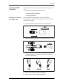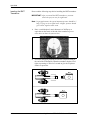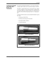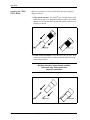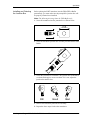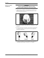
1
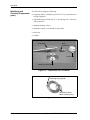
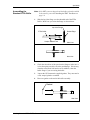
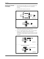
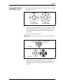
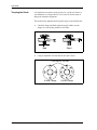
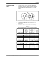
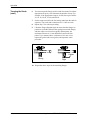
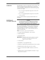
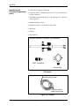
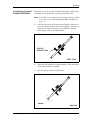
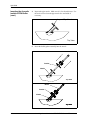
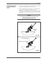
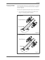
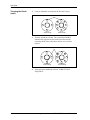
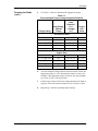
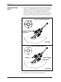
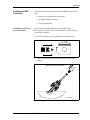
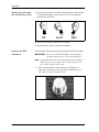
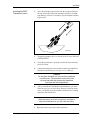
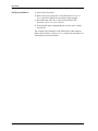
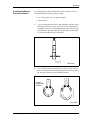
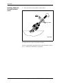
BWTTM System
Installation Guide
April 2004
Process Control Instruments
BWTTM System
Installation Guide
916-058B
April 2004
Table of Contents
Chapter 1: General Information
Introduction . . . . . . . . . . . . . . . . . . . . . . . . . . . . . . . . . . . . . . . . . . . . . . . . . . . . . . . . . . . . . . . . . .1-1
Types of BWT Buffers. . . . . . . . . . . . . . . . . . . . . . . . . . . . . . . . . . . . . . . . . . . . . . . . . . . . . . . . . .1-1
General Guidelines for Transducer Position and Location . . . . . . . . . . . . . . . . . . . . . . . . . . . . . .1-2
BWT Meter Body . . . . . . . . . . . . . . . . . . . . . . . . . . . . . . . . . . . . . . . . . . . . . . . . . . . . . . . . . . . . .1-3
Single-Traverse Meter Body. . . . . . . . . . . . . . . . . . . . . . . . . . . . . . . . . . . . . . . . . . . . . . . . . .1-3
Double-Traverse Meter Body . . . . . . . . . . . . . . . . . . . . . . . . . . . . . . . . . . . . . . . . . . . . . . . . .1-4
Handling and Installing a Meter Body . . . . . . . . . . . . . . . . . . . . . . . . . . . . . . . . . . . . . . . . . . . . .1-5
Unpacking a Meter Body . . . . . . . . . . . . . . . . . . . . . . . . . . . . . . . . . . . . . . . . . . . . . . . . . . . .1-5
Installing a Meter Body. . . . . . . . . . . . . . . . . . . . . . . . . . . . . . . . . . . . . . . . . . . . . . . . . . . . . .1-5
Welding Requirements. . . . . . . . . . . . . . . . . . . . . . . . . . . . . . . . . . . . . . . . . . . . . . . . . . . . . . . . . .1-6
Meter Body Requirements When Flushing . . . . . . . . . . . . . . . . . . . . . . . . . . . . . . . . . . . . . . . . . .1-7
Chapter 2: Installing Standard FTPA BWT Buffers and Transducers
Introduction . . . . . . . . . . . . . . . . . . . . . . . . . . . . . . . . . . . . . . . . . . . . . . . . . . . . . . . . . . . . . . . . . .2-1
Identifying and Checking Components . . . . . . . . . . . . . . . . . . . . . . . . . . . . . . . . . . . . . . . . . . . . .2-1
Assembling the Standard FTPA Buffer . . . . . . . . . . . . . . . . . . . . . . . . . . . . . . . . . . . . . . . . . . . . .2-3
Inserting the Standard FTPA Buffer . . . . . . . . . . . . . . . . . . . . . . . . . . . . . . . . . . . . . . . . . . . . . . .2-4
Torquing the Studs. . . . . . . . . . . . . . . . . . . . . . . . . . . . . . . . . . . . . . . . . . . . . . . . . . . . . . . . . . . . .2-6
Installing the BWT Transducer . . . . . . . . . . . . . . . . . . . . . . . . . . . . . . . . . . . . . . . . . . . . . . . . . . .2-9
Installing and Orienting the Junction Box . . . . . . . . . . . . . . . . . . . . . . . . . . . . . . . . . . . . . . .2-9
Inserting the BWT Transducer . . . . . . . . . . . . . . . . . . . . . . . . . . . . . . . . . . . . . . . . . . . . . . .2-10
Verifying Installation . . . . . . . . . . . . . . . . . . . . . . . . . . . . . . . . . . . . . . . . . . . . . . . . . . . . . .2-11
Chapter 3: Installing Acoustic Isolation FIPA BWT Buffers and Transducers
Introduction . . . . . . . . . . . . . . . . . . . . . . . . . . . . . . . . . . . . . . . . . . . . . . . . . . . . . . . . . . . . . . . . . .3-1
Identifying and Checking Components . . . . . . . . . . . . . . . . . . . . . . . . . . . . . . . . . . . . . . . . . . . . .3-1
Inserting the Acoustic Isolation FIPA Buffer . . . . . . . . . . . . . . . . . . . . . . . . . . . . . . . . . . . . . . . .3-3
Torquing the Studs. . . . . . . . . . . . . . . . . . . . . . . . . . . . . . . . . . . . . . . . . . . . . . . . . . . . . . . . . . . . .3-7
Installing the BWT Transducer . . . . . . . . . . . . . . . . . . . . . . . . . . . . . . . . . . . . . . . . . . . . . . . . . . 3-11
Installing the Orienting the Junction Box . . . . . . . . . . . . . . . . . . . . . . . . . . . . . . . . . . . . . . .3-11
Inserting the BWT Transducer . . . . . . . . . . . . . . . . . . . . . . . . . . . . . . . . . . . . . . . . . . . . . . .3-12
Verifying Installation . . . . . . . . . . . . . . . . . . . . . . . . . . . . . . . . . . . . . . . . . . . . . . . . . . . . . .3-14
Installing Additional Acoustic Isolation . . . . . . . . . . . . . . . . . . . . . . . . . . . . . . . . . . . . . . . . . . .3-15
Chapter 4: Installing Non-Flanged FSPA/FWPA BWT Buffers and Transducers
Installing Non-Flanged FSPA/FWPA BWT Buffers and Transducers . . . . . . . . . . . . . . . . . . . . .4-1
Installing the FSPA/FWPA Buffer . . . . . . . . . . . . . . . . . . . . . . . . . . . . . . . . . . . . . . . . . . . . .4-2
Installing and Orienting the Junction Box . . . . . . . . . . . . . . . . . . . . . . . . . . . . . . . . . . . . . . .4-3
Inserting the BWT Transducers . . . . . . . . . . . . . . . . . . . . . . . . . . . . . . . . . . . . . . . . . . . . . . .4-4
Verifying Installation . . . . . . . . . . . . . . . . . . . . . . . . . . . . . . . . . . . . . . . . . . . . . . . . . . . . . . .4-5
Chapter 5: Specifications
Specifications. . . . . . . . . . . . . . . . . . . . . . . . . . . . . . . . . . . . . . . . . . . . . . . . . . . . . . . . . . . . . . . . .5-1
iii
April 2004
Warranty
Each instrument manufactured by GE Panametrics is warranted to be
free from defects in material and workmanship. Liability under this
warranty is limited to restoring the instrument to normal operation or
replacing the instrument, at the sole discretion of GE Panametrics. Fuses
and batteries are specifically excluded from any liability. This warranty
is effective from the date of delivery to the original purchaser. If GE
Panametrics determines that the equipment was defective, the warranty
period is:
•
one year for general electronic failures of the instrument
•
one year for mechanical failures of the sensor
If GE Panametrics determines that the equipment was damaged by
misuse, improper installation, the use of unauthorized replacement parts,
or operating conditions outside the guidelines specified by GE
Panametrics, the repairs are not covered under this warranty.
The warranties set forth herein are exclusive and are in lieu of
all other warranties whether statutory, express or implied
(including warranties or merchantability and fitness for a
particular purpose, and warranties arising from course of
dealing or usage or trade).
Return Policy
If a GE Panametrics instrument malfunctions within the warranty period,
the following procedure must be completed:
1. Notify GE Panametrics, giving full details of the problem, and
provide the model number and serial number of the instrument. If the
nature of the problem indicates the need for factory service, GE
Panametrics will issue a RETURN AUTHORIZATION NUMBER
(RAN), and shipping instructions for the return of the instrument to a
service center will be provided.
2. If GE Panametrics instructs you to send your instrument to a service
center, it must be shipped prepaid to the authorized repair station
indicated in the shipping instructions.
3. Upon receipt, GE Panametrics will evaluate the instrument to
determine the cause of the malfunction.
Then, one of the following courses of action will then be taken:
iv
•
If the damage is covered under the terms of the warranty, the
instrument will be repaired at no cost to the owner and returned.
•
If GE Panametrics determines that the damage is not covered under
the terms of the warranty, or if the warranty has expired, an estimate
for the cost of the repairs at standard rates will be provided. Upon
receipt of the owner’s approval to proceed, the instrument will be
repaired and returned.
Chapter 1
General Information
Introduction . . . . . . . . . . . . . . . . . . . . . . . . . . . . . . . . . . . . . . . . . . . 1-1
Types of BWT Buffers . . . . . . . . . . . . . . . . . . . . . . . . . . . . . . . . . . . 1-1
General Guidelines for Transducer Position and Location . . . . . 1-2
BWT Meter Body. . . . . . . . . . . . . . . . . . . . . . . . . . . . . . . . . . . . . . . . 1-3
Handling and Installing a Meter Body . . . . . . . . . . . . . . . . . . . . . . 1-5
Welding Requirements. . . . . . . . . . . . . . . . . . . . . . . . . . . . . . . . . . . 1-6
Meter Body Requirements When Flushing . . . . . . . . . . . . . . . . . .1-7
April 2004
Introduction
Installing the BWTTM System consists of creating a meter body,
installing the transducer buffer, and then mounting transducers into
the buffer. GE Panametrics offers a variety of buffers and meter
bodies for liquid and gas applications. This section consists of general
information for the following:
•
Types of BWT Buffers
•
General Guidelines for Transducer Position and Location
•
BWT Meter Body
•
Handling and Installing a Meter Body
•
Welding Requirements
•
Meter Body Requirements When Flushing
Refer to the appropriate section of this manual to install the BWT
buffers and transducers that you ordered.
Types of BWT Buffers
Buffers are used to protect the BWT transducers from temperature
extremes. Since they mount directly into the pipe coupling or nozzle,
they also act as barriers against the process, making it possible for the
transducers to be removed without interrupting the process or
emptying the pipe. There are three BWT buffer types available for
transducers for liquid and gas applications:
•
Standard BWT Buffer (part number
FTPA) - is used for liquid and gas
applications. The buffer has a flanged
process connection and is available in
two lengths: 2 in. (temperatures up to
600oF/315oC) and 6 in. (temperatures
up to 1,100oF/600oC).
•
Acoustic Isolation BWT Buffer (part
number FIPA) - is used for gas
applications at lower pressures. The
buffer has a flanged isolation section
that reduces acoustic short circuit. The
outer buffer has a flanged process
connection and is available in two
lengths: 2 in. (temperatures up to
600oF/315oC) and 6 in. (temperatures
up to 1,100oF/600oC).
General Information
1-1
April 2004
Types of BWT Buffers
(cont.)
General Guidelines for
Transducer Position
and Location
•
Non-Flanged BWT Buffer (part
number FSPA) - is used in liquid
applications and has a 1 in. NPT
thread.
•
Socket-Weld BWT Buffer (part
number FWPA) - is used in liquid
applications and has a 1 in. coupling
that is welded into the pipe coupling.
Whichever transducer type is selected for your installation, flowmeter
accuracy depends on proper transducer location, spacing, alignment,
and electronics programming. However, even though every
transducer installation has specific location considerations, the
following location guidelines apply to all transducers, regardless of
type:
Caution!
A flowmeter’s accuracy and performance depends
on the location, spacing, and alignment
of the transducers. The specific spacing of your
transducers are unique to your installation.
1. To help assure a uniform flow profile, locate the buffers so that
there are at least 10 pipe diameters of straight, undisturbed flow
upstream and 5 pipe diameters of straight, undisturbed flow
downstream from the point of measurement. The more straight run
available the better. “Undisturbed flow” means avoiding sources
of turbulence such as valves, flanges, and elbows. You should also
avoid swirl, cross flow and cavitation (in liquids).
2. It is important to locate the transducers on a horizontal plane. This
specifically applies to mounting transducers on a horizontal pipe.
One transducer cannot be on top of the pipe and one on the
bottom, because the top of the pipe tends to accumulate gas (in
liquids) and the bottom tends to accumulate sediment (in gas and
liquids). These contaminants can attenuate or block the ultrasonic
signal. There is no similar restriction with vertical pipes. However,
in liquid applications you should avoid vertical downward flow to
ensure a full pipe.
1-2
General Information
April 2004
BWT Meter Body
BWT installations typically use a tilted-diameter meter body. A tilteddiameter meter body is so named because the transducers send their
pulses at an angle across the diameter of the pipe. This type of meter
body can be configured as a single-traverse or double-traverse
installation.
Note: The mounting angle for the transducer is typically 45°, but
other angles (20°, 30°, or 60°) can be used as required. Tilted
diameter can also refer to paths that are off-diameter such as
the mid-radius path.
A meter body is created by mounting the nozzles on the existing
pipeline, or on a meter body. A meter body is a precisionmanufactured section of matching pipe that contains the ports where
the transducer buffers will be mounted. This setup allows more
accurate transducer alignment before mounting the meter body into
the pipeline. If requested, a meter body can be calibrated prior to
shipment. All meter bodies are factory-supplied.
Single-Traverse Meter
Body
A single-traverse configuration consists of two transducers mounted
on opposite sides of the pipe so that the signal they transmit passes
through the fluid just once, at a typical 45° angle (Figure 1-1 below).
A single-traverse configuration may include more than one path
(Figure 1-2 on the next page).
Top View
End View
Figure 1-1: Single-Traverse, 2-Path, Diagonal 45 Meter
Body
General Information
1-3
April 2004
Single-Traverse Meter
Body (cont.)
Top
Figure 1-2: Single-Traverse, 2-Path, Mid-Radius Meter
Body
Double-Traverse Meter
Body
A double-traverse configuration consists of two transducers mounted
on the pipe so that the signal traverses the fluid two times before
reaching the other transducer. See Figure 1-3 below.
P = Distance that the signal travels
through the liquid from one
transducer to the other.
P
TOP
o
o
45
45
L
L = Projected distance of
acoustical path in liquid.
Figure 1-3: Double-Traverse Meter Body
1-4
General Information
April 2004
Handling and Installing
a Meter Body
To ensure proper nozzle alignment, GE Panametrics uses the highest
quality welding and machining techniques when manufacturing meter
bodies. Since proper alignment of the nozzles is important to making
accurate flow measurement, great care must be taken when unpacking
and installing the meter body.
Unpacking a Meter Body
Upon receipt, you should take great care in unpacking the meter body.
Although meter bodies are constructed of steel, improper unpacking
or handling can result in damage or affect nozzle alignment. Use the
guidelines below for unpacking the meter body:
Installing a Meter Body
•
Since the nozzles protrude from the pipe, take care when
removing packing material and the meter body from its
shipping container, so as not to disturb the nozzles.
•
After the meter body is removed from its shipping container,
never allow the full weight of the meter body to rest on the
nozzle or buffer. You should prop up the meter body to prevent
it from rolling over, which again, may cause damage or
misalignment of nozzles.
•
Do not let the meter body hit against other objects or surfaces.
Nozzle alignment can be affected if the meter body is dropped
onto sand or the ground.
•
If the meter body is shipped with the buffers already installed in
the nozzles, take care as to not disturb the buffers when
unpacking.
Meter bodies can be either flanged or welded into the existing
pipeline. Use the following steps to position the meter body into the
pipeline (refer to Figure 1-4 on the next page):
!WARNING!
Before installing the meter body make sure pipe
flushing is completed. For additional information
when flushing is necessary, refer to Meter Body
Requirements When Flushing on page 1-7.
1. Find the tag plate with the words TOP and FLOW DIRECTION
marked on it. If the meter body is flanged, two bolt holes should
straddle the vertical centerline.
IMPORTANT: In general (including cases where the meter body
axis is not horizontal), be sure that the installation
does not allow gas or sediment to deposit in the
transducer ports. Otherwise the sound waves could
be attenuated or blocked entirely.
General Information
1-5
April 2004
Installing a Meter Body
(cont.)
2. Place the meter body in the pipeline so that the FLOW
DIRECTION arrow mark is in the direction of flow and the top is
appropriately located. (Be sure the transducer ports are in a
horizontal plane.)
IMPORTANT: If you cannot place the meter body in the required
orientation, consult the factory; otherwise
operational problems may occur.
3. Do one of the following:
•
Bolt the meter body into place and proceed to the appropriate
section that follows to mount the BWT buffers and transducers.
•
Weld the meter body into place in accordance with the
requirements described in Welding Requirements below. Once
welding is completed, proceed to the appropriate section that
follows to mount the BWT buffers and transducers.
Bolt holes straddle
centerline symmetrically
TOP
Top View
End View
Figure 1-4: Top View of a Flanged Meter Body
Welding Requirements
1-6
Prior to welding, do the following:
•
Remove power from the flowmeter console and disconnect the
cables from the transducers.
•
Make sure the inside diameter of the meter body and process
pipe are properly aligned. Misalignment can affect
measurement accuracy.
General Information
April 2004
Meter Body
Requirements When
Flushing
GE Panametrics strongly recommends using a dummy meter body
during flushing operations; otherwise, damage may occur for the
following reasons:
•
Fast moving solid objects in the flowing medium could damage
the buffer faces.
•
Flushing residue/sediment could clog nozzles.
In the event that a dummy meter body is not available for flushing
operations, remove the buffers and plug the holes properly for the
temperature and pressure used. Blind flanges are typically used.
Reinstall the buffers and transducers after flushing using the
information in this guide.
Caution!
Be sure to use new gaskets when reinstalling buffers.
Never reuse gaskets for safety reasons and acoustic
performance of the flowmeter.
General Information
1-7
Chapter 2
Installing Standard FTPA BWT Buffers and
Transducers
Introduction . . . . . . . . . . . . . . . . . . . . . . . . . . . . . . . . . . . . . . . . . . . 2-1
Identifying and Checking Components . . . . . . . . . . . . . . . . . . . . . 2-1
Assembling the Standard FTPA Buffer . . . . . . . . . . . . . . . . . . . . . 2-3
Inserting the Standard FTPA Buffer . . . . . . . . . . . . . . . . . . . . . . . . 2-4
Torquing the Studs. . . . . . . . . . . . . . . . . . . . . . . . . . . . . . . . . . . . . . 2-6
Installing the BWT Transducer . . . . . . . . . . . . . . . . . . . . . . . . . . . . 2-9
April 2004
Introduction
The FTPA Buffer is used for liquid and gas applications. The buffer
has a flanged process connection and is typically available in two
lengths:
•
2 in. × 6 in. for low temperature ranges from -150 to 315oC
(-270 to 600oF)
•
6 in. × 6 in. for high temperature ranges from -150 to 600oC
(-270 to 1,100oF).
Use the sections that follow to properly install the buffers and
transducers.
Identifying and
Checking Components
Caution!
It is critical that you follow the instructions outlined in
this document. If you do not, GE Panametrics cannot
ensure the proper operation of your equipment.
Before you install the FTPA Buffer you should make sure you have
all the needed equipment. Use the lists below to identify the needed
components. GE Panametrics will supply you with the following (use
Figures 2-1 and 2-2 on the next page to help you identify each
component):
Note: The list below is for a one-path installation.
•
2 FTPA Buffers
•
2 BWT1 transducers
•
2 Kamprofile gaskets
IMPORTANT: Kamprofile gaskets must be used for two reasons:
they ensure a leak tight seal and they provide
necessary acoustic isolation.
•
2 Mating lap-joint flanges
•
2 Junction boxes
•
Preamplifier(s) - for gas application only
•
3M epoxy or equivalent (for permanent bond) (not shown in photo)
•
Required studs, nuts and washers (not shown in photo)
•
10 ft (3 m) Coaxial cable with BNC connectors (not shown in
photo)
•
Additional cable to connect preamplifier to electronics - for gas
only (not shown in photo)
Installing Standard FTPA BWT Buffers and Transducers
2-1
April 2004
Identifying and
Checking Components
(cont.)
You will need to supply the following:
•
Copperslip (SS316), Molykote grease P47 (CS) or equivalent antiseizing compound
•
Adjustable torque wrench with 15 - 148 ft-lb range (20 - 200 N-m)
with socket drive
•
standard and deep sockets
•
adjustable wrench (12 in. handle or equivalent)
•
Steel wool
•
Calipers
.
FTPA Buffer
BWT
Transducer
Junction Box
Mating Lap-Joint Flange
Figure 2-1: Components for FTPA Buffer
Kamprofile with Metal
Centering Ring (Typical)
Kamprofile without
Metal Centering Ring
Figure 2-2: Gaskets
2-2
Installing Standard FTPA BWT Buffers and Transducers
April 2004
Assembling the
Standard FTPA Buffer
Note: If the BWT system is shipped with the buffers already installed
in the nozzles, proceed to Installing the BWT Transducer on
page 2-9.
1.
Slide the lap-joint flange over the threaded end of the FTPA
Buffer. Make sure you orient the flange as shown below.
Lap-Joint Flange
FTPA Buffer
Coupler Raised Face
Raised Edge
Side View
Side View
2.
Check the raised face of the spool nozzle flange to make sure it
is free from paint, rust, dirt, corrosion, and damage. If necessary,
clean the raised faces with steel wool. In addition, clean the
buffer flange if you are reusing the buffer.
3.
Inspect the GE Panametrics-supplied gaskets. They must not be
used, warped, pitted or scratched.
4.
Place one gasket on the end of the buffer assembly.
Gasket
Side View
Installing Standard FTPA BWT Buffers and Transducers
2-3
April 2004
Inserting the Standard
FTPA Buffer
1.
Inspect the pipe nozzle. Make sure it is free from dirt/rust. Use
the steel wool to clean the pipe nozzle face and inside if
necessary.
2.
Insert the buffer assembly into the nozzle.
Nozzle
Side View
Side View
3.
Apply Copperslip, Molykote or equivalent anti-seize compound
on the first several threads at both ends each stud.
4.
Insert one stud through the flanges. Make sure the stud quality
rating (e.g., B7) is facing away from the meter body.
Hand-tighten a washer and nut on to each end of the stud. Make
sure you leave an equal number of threads exposed on each end
of the stud.
Side View
Equal Amount of Threads
Stud Quality Rating
Side View
2-4
Installing Standard FTPA BWT Buffers and Transducers
April 2004
Inserting the Standard
FTPA Buffer (cont.)
5.
Install the remaining studs in the order shown below, but do not
tighten the nuts yet.
1
1
5
3
4
4
3
7
2
4-Hole Flange
8
2
6
8-Hole Flange
6.
Center the buffer in the middle of the lap joint flange. Feel 360
degrees around the flanges to ensure equal spacing, by placing
your hands around the diameter of the buffer flange and the
nozzle flange.
7.
Align the flanges as shown below.
IMPORTANT: Make sure the gasket is in the center of the flanges.
Flange
Proper Gasket
Alignment
End View
Good
Bad
End View
8.
Tighten the nuts and studs further by hand to maintain the
centering. Visually inspect that the buffer is centered in the lap
joint flange; if necessary, adjust the buffer by hand until it is
centered.
Installing Standard FTPA BWT Buffers and Transducers
2-5
April 2004
Torquing the Studs
It is important to torque the studs properly for a good seal. However,
you should not over-torque them so as to cause an acoustic short or
change the transducer alignment.
The studs must be tightened and torqued in stages as described below.
1.
Check the flange and buffer alignment again. Make sure the
flanges are consistently parallel to each other.
Bad
2.
Good
Using an adjustable wrench, turn the first nut 1/8 turn.
Turn first nut 1/8 turn.
1
3
5
4
2
4-Hole Flange
2-6
1
8
4
3
7
2
6
8-Hole Flange
Installing Standard FTPA BWT Buffers and Transducers
April 2004
Torquing the Studs
(cont.)
3.
Turn the second nut 1/8 turn. The second stud should be
diametrically opposite the first stud. Proceed to tighten the
remaining studs in the order shown below, or in a similar
manner.
Turn second nut 1/8 turn.
1
3
5
4
4-Hole Flange
8
4
3
7
2
1
2
6
8-Hole Flange
4.
Turn each nut an additional 1/8 turn. TURN NUTS IN
SEQUENCE.
5.
Use Table 2-1 below to determine the appropriate torque.
Table 2-1:
Recommended Torque (using Kamprofile Gaskets)
Flange Rating
Stud
Rating
4 Studs/
Flange
Stud
Diameter
(in.)
x Length (in.)
Torque
ft-lb
(N-m)
316 Stainless Steel
1 1/2" ANSI 150#
B8M,C,1
1/2" x 3 1/4"
56 (76)
1 1/2" ANSI 300#
B8M,C,1
3/4" x 4 3/4"
82 (111)
1 1/2" ANSI 600#
B8M,C,1
3/4" x 4 3/4"
82 (111)
1 1/2" ANSI 900#
B8M,C,1
1" x 6 "
107 (145)
1 1/2" ANSI 1500#
B8M,C,1
1" x 6"
107 (145)
Carbon Steel
1 1/2" ANSI 150#
B7
1/2" x 3 1/4"
56 (76)
1 1/2" ANSI 300#
B7
3/4" x 4 3/4"
82 (111)
1 1/2" ANSI 600#
B7
3/4" x 4 3/4"
82 (111)
1 1/2" ANSI 900#
B7
1" x 6 "
107 (145)
1 1/2" ANSI 1500#
B7
1" x 6"
107 (145)
Installing Standard FTPA BWT Buffers and Transducers
2-7
April 2004
Torquing the Studs
(cont.)
6.
You must torque the flange studs in small increments. Divide the
appropriate torque by 10 to determine the number of steps. For
example, if the appropriate torque is 90 ft-lb, the steps would be
20, 30, 40, 50, 60, 70, 80 and 90 ft-lb.
7.
Set the torque wrench for the first setting and torque the studs in
sequence. Turn each stud a maximum of a 1/8 turn at a time.
8.
Repeat Step 7 for each torque setting.
9.
Check the flange alignment again to ensure that the flanges are
parallel to each other. Measure the spacing between the flanges
with the caliper on at least four equally distant points; the
maximum tolerance is 0.2 mm difference between the four
points. If you cannot achieve a tolerance of 0.2 mm or less,
replace the gasket with a new gasket, and repeat the entire
procedure.
Caliper
Wrong
Right
10. Repeat the above steps for the remaining flanges.
2-8
Installing Standard FTPA BWT Buffers and Transducers
April 2004
Installing the BWT
Transducer
Installing and Orienting
the Junction Box
Installing the BWT transducers into the FTPA Buffer requires three
steps:
•
Installing and Orienting the Junction Box
•
Inserting the BWT transducers
•
Verifying Installation
Before placing the BWT transducer into the FTPA Buffer
permanently, you must make sure the junction box will be properly
oriented once installed.
1. Screw the transducer into the junction box as shown below.
2. Screw the transducer/junction box assembly into the FTPA Buffer.
3. Check the junction box orientation. The junction box lid should be
at a downward angle so water can drain. If it is not, adjust the
junction box until it does.
OK
Good
Bad
4. Remove the transducer/junction box assembly.
5. Repeat the above steps for the other transducer.
Installing Standard FTPA BWT Buffers and Transducers
2-9
April 2004
Inserting the BWT
Transducer
Please read the following steps before installing the BWT transducer.
IMPORTANT: After you install the BWT transducers, you must
allow the epoxy to cure for eight hours.
Note: In gas applications, the typical minimum pressure should be 5
barg (75 psig) to see a signal at all. A higher pressure should
give a better signal-to-noise ratio.
2-10
1.
Place a small droplet (2 mm in diameter) of 3M Epoxy or
equivalent on the center of the end of the transducer (picture
below does not show the junction box).
2.
Screw the transducer/junction box into the receptacle fitting at
the end of the FTPA Buffer. When the transducer begins to feel
tight, stop turning it. Wait for 5 seconds to give the couplant a
chance to spread out.
.
Installing Standard FTPA BWT Buffers and Transducers
April 2004
Inserting the BWT
Transducer (cont.)
3.
Torque the transducer to 15 to 18 ft-lb (20 to 25 N-m). DO NOT
OVERTIGHTEN.
4.
Verify the junction box is properly oriented as discussed in the
pervious section.
5.
Connect the transducer to the electronics and/or preamplifier as
described in the flowmeter’s Startup or User’s Manual.
Caution!
Do not place insulation on or around the transducer
or junction box. The transducer and junction box
act as a heat sink that protects the transducer
from high and low temperatures.
6. After you install the FTPA Buffers and transducers, you must
allow the epoxy to cure for 8 hours. However, while the epoxy
cures, you should verify the transducer and buffer are working
properly as described below.
Caution!
While the epoxy cures, do not remove, re-torque or
adjust the transducer or you will crack the epoxy.
7. Repeat the above steps for the other transducer.
Verifying Installation
1. Power up the electronics.
2. Refer to Displaying Diagnostics in the flowmeter’s Service or
User’s Manual to display the up and down signal strength.
3. Record this data in the Service Record in the back of the
flowmeter’s Service or User’s Manual.
4. Verify that the signal strength diagnostics are the same or better
after 8 hours.
This completes the installation of the FTPA buffers and transducers.
Refer to the flowmeter’s Startup or User’s Manual for instructions on
obtaining flow rate measurements.
Installing Standard FTPA BWT Buffers and Transducers
2-11
Chapter 3
Installing Acoustic Isolation FIPA BWT Buffers and
Transducers
Introduction . . . . . . . . . . . . . . . . . . . . . . . . . . . . . . . . . . . . . . . . . . . 3-1
Identifying and Checking Components . . . . . . . . . . . . . . . . . . . . . 3-1
Inserting the Acoustic Isolation FIPA Buffer . . . . . . . . . . . . . . . . . 3-3
Torquing the Studs. . . . . . . . . . . . . . . . . . . . . . . . . . . . . . . . . . . . . . 3-7
Installing the BWT Transducer . . . . . . . . . . . . . . . . . . . . . . . . . . . 3-11
Installing Additional Acoustic Isolation . . . . . . . . . . . . . . . . . . . . 3-15
April 2004
Introduction
The FIPA Buffer is used for gas applications at lower pressures. The
buffer has a flanged isolation section that reduces acoustic short
circuit. The buffer has a flanged process connection and is typically
available in two lengths:
•
2 in. × 6 in. for low temperature ranges from -150 to 315oC
(-270 to 600oF)
•
6 in. × 6 in. for high temperature ranges from -150 to 600oC
(-270 to 1,100oF).
Use the sections that follow to properly install the buffers and
transducers.
Identifying and
Checking Components
Caution!
It is critical that you follow the instructions outlined in
this document. If you do not, GE Panametrics cannot
ensure the proper operation of your equipment.
Before you install the BWT transducers you should make sure you
have all the needed equipment. Use the list below to identify the
needed components. GE Panametrics will supply you with the
following (see Figures 3-1 and 3-2 on the next page to help you
identify each component):
Note: The list below is for a one-path installation.
•
2 Acoustic Isolation FIPA Buffers - fully assembled
•
2 BWT1 transducers
•
2 Kamprofile gaskets
IMPORTANT: Kamprofile gaskets must be used for two reasons:
they ensure a leak tight seal and they provide
sufficient acoustic isolation.
•
2 Junction boxes
•
Preamplifier(s) - for gas application only
•
3M epoxy or equivalent (for permanent bond) (not shown in photo)
•
Required studs, nuts and washers (not shown in photo)
•
10 ft (3 m) Coaxial cable with BNC connectors (not shown in
photo)
•
Additional cable to connect preamplifier to electronics - for gas
only (not shown in photo)
Installing Acoustic Isolation FIPA BWT Buffers and Transducers
3-1
April 2004
Identifying and
Checking Components
(cont.)
You will need to supply the following:
•
Copperslip (SS316), Molykote grease P47 (CS) or equivalent antiseizing compound
•
Adjustable torque wrench with 15 - 148 ft-lb range (20 - 200 N-m)
with socket drive
•
standard and deep sockets
•
adjustable wrench (12 in. handle or equivalent)
•
Steel wool
•
Calipers
•
Tape Measure
.
Acoustic Isolation FIPA Buffer - fully assembled
BWT Transducer
Junction Box
Figure 3-1: Components for Acoustic Isolation
FIPA Buffer
Kamprofile with Metal
Centering Ring (Typical)
Kamprofile without
Metal Centering Ring
Figure 3-2: Gaskets
3-2
Installing Acoustic Isolation FIPA BWT Buffers and Transducers
April 2004
Inserting the Acoustic
Isolation FIPA Buffer
When you receive the Acoustic Isolation FIPA Buffer it will be fully
assembled. Use the steps below to properly install the buffer.
Note: If the BWT system is shipped with the buffers already installed
in the nozzles, proceed to Installing the BWT Transducer on
page 3-11.
1.
Check the raised face of the spool nozzle flange to make sure it
is free from paint, rust, dirt, corrosion, and damage. If necessary,
clean the raised faces with steel wool. In addition, clean the
buffer flange if you are reusing the buffer.
Inspect
Raised Face
Side View
2.
Inspect the GE Panametrics-supplied gaskets. They must not be
used, warped, pitted or scratched.
3.
Place one gasket on the end of the buffer.
Gasket
Side View
Installing Acoustic Isolation FIPA BWT Buffers and Transducers
3-3
April 2004
Inserting the Acoustic
Isolation FIPA Buffer
(cont.)
4.
Inspect the pipe nozzle. Make sure it is free from dirt/rust. Use
the steel wool to clean the pipe nozzle face and inside if
necessary.
Inspect Pipe Nozzle
Top View
5.
Insert the buffer/gasket assembly into the nozzle.
Gasket
Nozzle
Top View
Buffer
Gasket
Nozzle
Top View
3-4
Installing Acoustic Isolation FIPA BWT Buffers and Transducers
April 2004
Inserting the Acoustic
Isolation FIPA Buffer
(cont.)
6.
Apply Copperslip, Molykote or equivalent anti-seize compound
on the first several threads at both ends each stud.
7.
Insert one stud through the flanges. Make sure the stud quality
rating (e.g., B7) is facing away from the meter body.
Hand-tighten a washer and nut on to each end of the stud. Make
sure you leave an equal number of threads exposed on each end
of the stud.
Caution!
Do not adjust the studs on the FIPA isolation flange.
The isolation flange is already set to
specification determined at the factory.
Isolation
Flange
Top View
Stud Quality Rating
Equal Amount of Threads
Top View
Installing Acoustic Isolation FIPA BWT Buffers and Transducers
3-5
April 2004
Inserting the Acoustic
Isolation FIPA Buffer
(cont.)
8.
Install the remaining stud in the order shown below, but do not
tighten the nuts yet.
1
5
3
4
4-Hole Flange
9.
8
4
3
7
2
1
2
6
8-Hole Flange
Run your hands around the diameter of the buffer flange and
nozzle flange to ensure equal spacing.
10. Then align the flanges as shown below.
IMPORTANT: Make sure the gasket is in the center of the flanges.
Flange
Proper Gasket
Alignment
End View
Good
Bad
End View
11. Once you have centered the buffer, tighten the studs further by
hand to maintain the centering. Visually inspect that the buffer is
centered in the lap joint flange; if necessary, adjust the buffer by
hand until it is centered.
3-6
Installing Acoustic Isolation FIPA BWT Buffers and Transducers
April 2004
Torquing the Studs
You must torque the studs to give a good seal. However, you should
not over torque them so as to cause an acoustic short or change the
transducer alignment.
The nuts must be tightened and torqued in stages as described below.
1.
Check the flange and buffer alignment again. Make sure the
flanges are consistently parallel to each other.
Bad Alignment
Unequal Distances
Not Centered
Top View
Proper Alignment
Equal Distances
Centered
Top View
Installing Acoustic Isolation FIPA BWT Buffers and Transducers
3-7
April 2004
Torquing the Studs
(cont.)
2.
Using an adjustable wrench, turn the first nut 1/8 turn.
.
Turn first nut 1/8 turn.
1
5
3
4
8
4
3
7
2
4-Hole Flange
3.
1
2
6
8-Hole Flange
Turn the second nut 1/8 turn. The second stud should be
diametrically opposite the first stud. Proceed to turn the
remaining studs in the order shown below, or in a similar
manner.
Turn second nut 1/8 turn.
1
3
4
2
4-Hole Flange
4.
3-8
5
1
8
4
3
7
2
6
8-Hole Flange
Turn each nut an additional 1/8 turn. TURN NUTS IN
SEQUENCE.
Installing Acoustic Isolation FIPA BWT Buffers and Transducers
April 2004
Torquing the Studs
(cont.)
5.
Use Table 3-1 below to determine the appropriate torque.
Table 3-1:
Recommended Torque (using Kamprofile Gaskets)
Flange Rating
Stud
Diameter
(in.)
x Length
(in.)
Stud Rating
4 Studs/
Flange
Torque
ft-lb
(N-m)
316 Stainless Steel
1 1/2" ANSI 150#
B8M,C,1
1/2" x 3 1/4"
56 (76)
1 1/2" ANSI 300#
B8M,C,1
3/4" x 4 3/4"
82 (111)
1 1/2" ANSI 600#
B8M,C,1
3/4" x 4 3/4"
82 (111)
1 1/2" ANSI 900#
B8M,C,1
1" x 6 "
107 (145)
1 1/2" ANSI 1500#
B8M,C,1
1" x 6"
107 (145)
Carbon Steel
1 1/2" ANSI 150#
B7
1/2" x 3 1/4"
56 (176)
1 1/2" ANSI 300#
B7
3/4" x 4 3/4"
82 (111)
1 1/2" ANSI 600#
B7
3/4" x 4 3/4"
82 (111)
1 1/2" ANSI 900#
B7
1" x 6 "
107 (145)
1 1/2" ANSI 1500#
B7
1" x 6"
107 (145)
6.
You must torque the flange studs in small increments. Divide the
appropriate torque by 10 to determine the number of steps. For
example, if the appropriate torque is 90 ft-lb, the steps would be
20, 30, 40, 50, 60, 70, 80 and 90 ft-lb.
7.
Set the torque wrench for the first setting and torque the studs in
sequence. Turn each stud a maximum of 1/8 of a turn at a time.
8.
Repeat Step 7 with the remaining torque settings.
Installing Acoustic Isolation FIPA BWT Buffers and Transducers
3-9
April 2004
Torquing the Studs
(cont.)
9.
Check the flange alignment again to ensure that the flanges are
parallel to each other. Measure the spacing between the flanges
with the caliper on at least four equally distant points; the
maximum tolerance is 0.2 mm difference between the four
points. If you cannot achieve tolerance of 0.2 mm or less, replace
the gasket with a new gasket, and repeat the entire procedure.
Improper Gasket Alignment
Improper Flange
Alignment
Top View
Proper Gasket Alignment
Caliper
Proper Flange
Alignment
Top View
10. Repeat the above steps for the remaining flanges.
3-10
Installing Acoustic Isolation FIPA BWT Buffers and Transducers
April 2004
Installing the BWT
Transducer
Installing the Orienting
the Junction Box
Installing the BWT transducers into the FIPA Buffer requires three
steps:
•
Installing and Orienting the Junction Box
•
Inserting the BWT transducers
•
Verifying Installation
Before placing the BWT transducer into the FIPA Buffer
permanently, you must make sure the junction box will be properly
oriented once installed.
1. Screw the transducer into the junction box as shown below.
2.
Screw the transducer/junction box assembly into the FIPA
Buffer.
BWT Transducer/Junction Box
Top View
Installing Acoustic Isolation FIPA BWT Buffers and Transducers
3-11
April 2004
Installing the Orienting
the Junction Box (cont.)
3. Check the junction box orientation. The junction box lid should be
at a downward angle so water can drain. If it is not, adjust the
junction box until it does.
OK
Good
Bad
4. Remove the transducer/junction box assembly.
5. Repeat the above steps for the other transducer.
Inserting the BWT
Transducer
Please read the following steps before installing the BWT transducer.
IMPORTANT: After you install the BWT Buffer and transducers,
you must allow the epoxy to cure for eight hours.
Note: In gas applications, the typical minimum pressure should be 5
barg (75 psig) to see a signal at all. A higher pressure will
give a better signal-to-noise ratio.
1.
3-12
Place a small droplet (2 mm in diameter) of 3M Epoxy or
equivalent on the center of the end of the transducer (picture
below does not show the junction box).
Installing Acoustic Isolation FIPA BWT Buffers and Transducers
April 2004
Inserting the BWT
Transducer (cont.)
2.
Screw the transducer/junction box into the receptacle fitting at
the end of the buffer. When the transducer begins to feel tight,
stop turning it. Wait for 5 seconds to give the couplant a chance
to spread out.
BWT Transducer/Junction Box
Top View
3.
Torque the transducer to 15 to 18 ft-lb (20 to 25 N-m). DO NOT
OVERTIGHTEN.
4.
Verify the junction box is properly oriented as discussed in the
previous section.
5.
Connect the transducer to the electronics and/or preamplifier as
described in the flowmeter’s Startup or User’s Manual.
Caution!
Do not place insulation on or around the transducer
or junction box. The transducer and junction box
act as a heat sink that protects the transducer
from high and low temperatures.
6.
After you install the FTPA Buffers and transducers, you must
allow the epoxy to cure for 8 hours. However, while the epoxy
cures, you should verify the transducer and buffer are working
properly as described below.
Caution!
While the epoxy cures, do not remove, re-torque or
adjust the transducer or you will crack the epoxy.
7. Repeat the above steps for the other transducer.
Installing Acoustic Isolation FIPA BWT Buffers and Transducers
3-13
April 2004
Verifying Installation
1. Power up the electronics.
2. Refer to Displaying Diagnostics in the flowmeter’s Service or
User’s Manual to display the up and down signal strength.
3. Record this data in the Service Record in the back of the
flowmeter’s Service or User’s Manual.
4. Verify that the signal strength diagnostics are the same or better
after 8 hours.
This completes the installation of the FIPA buffers and transducers.
Refer to the flowmeter’s Startup or User’s Manual for instructions on
obtaining flow rate measurements.
3-14
Installing Acoustic Isolation FIPA BWT Buffers and Transducers
April 2004
Installing Additional
Acoustic Isolation
If your application requires additional acoustic isolation, you will
need the following to perform this procedure:
1.
•
1 to 3 ring collets (for 4 in. pipes or larger)
•
Allen wrench
If you are using more than one collet, adjust the spacing rods on
each pipe riser fixture to 1 in. (25 mm). Use the drawing below
to properly set the rods. When adjusting the rods, make sure you
pay attention to how the collets will be positioned on the buffer
(i.e. how the collets will face each other).
1 in.
2.
Side View
Use an Allen wrench to separate the two pieces of the collet so
that it can be placed on the buffer. Repeat for the other collet(s).
Be sure not to mix pieces from different fixtures.
Loosen
Using Allen
Wrench
Front View
Installing Acoustic Isolation FIPA BWT Buffers and Transducers
3-15
April 2004
Installing Additional
Acoustic Isolation
(cont.)
3.
Place the collet(s) on the buffer as shown below.
1 in.
(25 mm)
Ring Collets
Top View
4. Repeat the above steps for the other transducer.
You have completed the installation. Refer to the flowmeter’s Startup
or User’s Manual for instructions on operation.
3-16
Installing Acoustic Isolation FIPA BWT Buffers and Transducers
Chapter 4
Installing Non-Flanged FSPA/FWPA BWT Buffers
and Transducers
Installing Non-Flanged FSPA/FWPA BWT Buffers and Transducers
4-1
April 2004
Installing Non-Flanged
FSPA/FWPA BWT
Buffers and
Transducers
The Non-Flanged FSPA/FWPA Buffer is a pipe plug and coupling
assembly made of stainless steel or titanium (see Figure 4-1 below).
The FSPA is a threaded buffer that is screwed into the pipe coupling
or nozzle. The FWPA is a socket-weld buffer that is welded into the
pipe coupling. Both types of buffers enable you to install and remove
transducers easily without interrupting the process or emptying the
pipe.
Installing the BWT transducers into the FSPA/FWPA Buffer requires
three steps:
•
Installing the FSPA/FWPA
•
Installing and Orienting the Junction Box
•
Inserting the BWT transducers
•
Verifying Installation
FSPA Threaded Mount
FWPA Socket-Weld Mount
Figure 4-1: Threaded FSPA/FWPA Buffer
Installing Non-Flanged FSPA/FWPA BWT Buffers and Transducers
4-1
April 2004
Installing the FSPA/
FWPA Buffer
Both types of buffers are easily installed into the pipe coupling or
flange as follows:
•
•
FSPA threaded mount - Use Teflon® tape or thread sealant on the
buffer threads and screw the buffer into the transducer port. Handtighten, once inserted the NPT threads will seal the connection; no
torquing is required.
FWPA socket-weld mount - Insert the buffer into the meter body
transducer port and weld in accordance with all applicable safety
codes and procedures.
!WARNING!
Welding should be performed by qualified
personnel only. Safety personnel
should be consulted.
4-2
Installing Non-Flanged FSPA/FWPA BWT Buffers and Transducers
April 2004
Installing and Orienting
the Junction Box
Before placing the BWT transducer into the FSPA/FWPA Buffer
permanently, you must make sure the preamplifier junction box will
be properly oriented once installed.
Note: The following drawings show the FSPA Buffer only.
1. Screw the transducer into the junction box as shown below.
2. Screw the transducer/junction box assembly into the FSPA/FWPA
Buffer.
3. Check the junction box orientation. The junction box lid should be
at a downward angle so water can drain. If it is not, adjust the
junction box until it does.
OK
Good
Bad
4. Remove the transducer/junction box assembly.
5. Repeat the above steps for the other transducer.
Installing Non-Flanged FSPA/FWPA BWT Buffers and Transducers
4-3
April 2004
Inserting the BWT
Transducers
!WARNING!
Follow all applicable safety codes and safety
procedures when installing or removing the plugs.
1. Apply the epoxy couplant (2 mm in diameter) to the flat face of
the BWT transducer and screw it into the buffer (picture below
does not show the junction box).
2. Hand-tighten transducers, then torque it to a maximum of 15 ft-lb
(20 N-m).
3. Check the junction box orientation. The junction box lid should be
at a downward angle so water can drain. If it is not, adjust the
junction box until it does.
OK
4.
4-4
Good
Bad
Connect the transducer to the preamplifier and electronics as
described in the flowmeter’s Startup or User’s Manual.
Installing Non-Flanged FSPA/FWPA BWT Buffers and Transducers
April 2004
Verifying Installation
1. Power up the electronics.
2. Refer to Displaying Diagnostics in the flowmeter’s Service or
User’s Manual to display the up and down signal strength.
3. Record this data in the Service Record in the back of the
flowmeter’s Service or User’s Manual.
4. Verify that the signal strength diagnostics are the same or better
after 8 hours.
This completes the installation of the FSPA/FWPA buffers and
transducers. Refer to the flowmeter’s Startup or User’s Manual for
instructions on obtaining flow rate measurements.
Installing Non-Flanged FSPA/FWPA BWT Buffers and Transducers
4-5
Chapter 5
Specifications
April 2004
Specifications
Table 5-1: BWT Transducer Specifications
Transducer
BWT for Liquids
BWT for Gases
Designation
Installation Type
Material
Field Mounting
Process Connection
Holder Type
Holder Ratings
Operating Frequency
Hazardous area applications;
High temperature and high preshigh temperature and high pres- sure applications; superheated
sure applications; petrochemical steam.
industry.
Wetted (removable under pressure)
Standard: 316LSS Optional: Titanium
Meter Body, cold tap
1.5” flanged (standard)
1” NPT
1” socket weld
1.5” flanged (standard)
FTPA, FIPA, FSPA, FWPA
150#, 300#, 600#, 900#, 1500# and 2500# Lapjoint
0.5 MHz
Standard: 200 kHz
Optional: 500 kHz
Pressure Range
100 to 3480 psig (2500# flange) 100 to 3480 psig (2500#
flange). Contact factory for
minimum pressure.
Electrical Rating
200 V peak-to-peak, 5 mA
Ambient Temperature
Range
North America: -20 to +60°C (-4 to +140°F)
Europe: -40 to +70°C (-40 to +158°F)
Process Temperature
Range
Standard: -190 to +300°C (-310 to +572°F)
Optional: -190 to +600oC (-310 to +1112°F)
Note: Mechanical buffer assembly (not transducer) is exposed to
process temperatures.
North American
Certification Explosion proof
Class I, Division 1, Group C, D
European Certification Flameproof
II 2 G, EEx d IIC T6 80°C
Tam -40 to 75oC (-40 to 167oF)
KEMA 01ATEX2051X
North American
Certification Weatherproof
IP66, TYPE 4X
200Vpp, 5mA
European Certification Weatherproof
Specifications
IP 66
5-1
DECLARATION
OF
CONFORMITY
GE Panametrics
Shannon Industrial Estate
Shannon, Co. Clare
Ireland
We,
declare under our sole responsibility that the
T5 Ultrasonic Flow Transducer
T8 Ultrasonic Flow Transducer
T11 Ultrasonic Flow Transducer
BWT Ultrasonic Flow Transducer
to which this declaration relates, are in conformity with the following standards:
• EN 50014:1997+A1+A2:1999
• EN 50018:2000
• II 2 G EEx d IIC T6
T5: KEMA01ATEX2045 X; T8: KEMA02ATEX2283 X;
T11: KEMA02ATEX2252; BWT: KEMA01ATEX2051 X
KEMA, Ultrechtseweg, 310 Arnhem, The Netherlands
• EN 61326:1998, Class A, Annex A, Continuous Unmonitored Operation
following the provisions of the 89/336/EEC EMC Directive and the 94/9/EC ATEX Directive.
The units listed above and any ancillary sample handling systems supplied with them do not bear CE
marking for the Pressure Equipment Directive, as they are supplied in accordance with Article 3, Section 3
(sound engineering practices and codes of good workmanship) of the Pressure Equipment Directive
97/23/EC for DN<25.
Shannon - July 1, 2003
Mr. James Gibson
GENERAL MANAGER
TÜV
TÜV ESSEN
ISO 9001
U.S.
CERT-DOC Rev G1
5/28/02
DECLARATION
DE
CONFORMITE
GE Panametrics
Shannon Industrial Estate
Shannon, Co. Clare
Ireland
Nous,
déclarons sous notre propre responsabilité que les
T5 Ultrasonic Flow Transducer
T8 Ultrasonic Flow Transducer
T11 Ultrasonic Flow Transducer
BWT Ultrasonic Flow Transducer
rélatif á cette déclaration, sont en conformité avec les documents suivants:
• EN 50014:1997+A1+A2:1999
• EN 50018:2000
• II 2 G EEx d IIC T6
T5: KEMA01ATEX2045 X; T8: KEMA02ATEX2283 X;
T11: KEMA02ATEX2252; BWT: KEMA01ATEX2051 X
KEMA, Ultrechtseweg, 310 Arnhem, The Netherlands
• EN 61326:1998, Class A, Annex A, Continuous Unmonitored Operation
suivant les régles de la Directive de Compatibilité Electromagnétique 89/336/EEC et d’ATEX 94/9/EC.
Les matériels listés ci-dessus ainsi que les systèmes d'échantillonnages pouvant être livrés avec, ne portent
pas le marquage CE de la directive des équipements sous pression, car ils sont fournis en accord avec la
directive 97/23/EC des équipements sous pression pour les DN<25, Article 3, section 3 qui concerne les
pratiques et les codes de bonne fabrication pour l'ingénierie du son.
Shannon - July 1, 2003
Mr. James Gibson
DIRECTEUR GÉNÉRAL
TÜV
TÜV ESSEN
ISO 9001
U.S.
CERT-DOC Rev G1
5/28/02
KONFORMITÄTSERKLÄRUNG
GE Panametrics
Shannon Industrial Estate
Shannon, Co. Clare
Ireland
Wir,
erklären, in alleiniger Verantwortung, daß die Produkte
T5 Ultrasonic Flow Transducer
T8 Ultrasonic Flow Transducer
T11 Ultrasonic Flow Transducer
BWT Ultrasonic Flow Transducer
folgende Normen erfüllen:
• EN 50014:1997+A1+A2:1999
• EN 50018:2000
• II 2 G EEx d IIC T6
T5: KEMA01ATEX2045 X; T8: KEMA02ATEX2283 X;
T11: KEMA02ATEX2252; BWT: KEMA01ATEX2051 X
KEMA, Ultrechtseweg, 310 Arnhem, The Netherlands
• EN 61326:1998, Class A, Annex A, Continuous Unmonitored Operation
gemäß den Europäischen Richtlinien, Niederspannungsrichtlinie EMV-Richtlinie Nr.: 89/336/EG und
ATEX Richtlinie Nr. 94/9/EG.
Die oben aufgeführten Geräte und zugehörige, mitgelieferte Handhabungssysteme tragen keine CEKennzeichnung gemäß der Druckgeräte-Richtlinie, da sie in Übereinstimmung mit Artikel 3, Absatz 3
(gute Ingenieurpraxis) der Druckgeräte-Richtlinie 97/23/EG für DN<25 geliefert werden.
Shannon - July 1, 2003
Mr. James Gibson
GENERALDIREKTOR
TÜV
TÜV ESSEN
ISO 9001
U.S.
CERT-DOC Rev G1
5/28/02
ATEX COMPLIANCE
GE Panametrics
221 Crescent Street, Suite 1
Waltham, MA 02453
U.S.A.
We,
as the manufacturer, declare under our sole responsibility that the product
Type BWT Ultrasonic Flow Transducer
to which this document relates, in accordance with the provisions of ATEX Directive 94/9/EC Annex II,
meets the following specifications:
1180
II 2 G EEx d IIC T6
KEMA01ATEX2051X -40°C to +70°C, 200 Vpp, 5 mA
Furthermore, the following additional requirements and specifications apply to the product:
• Having been designed in accordance with EN 50014 and EN 50018, the product meets the fault
tolerance requirements of electrical apparatus for category “d”.
• The product is an electrical apparatus and must be installed in the hazardous area in accordance with
the requirements of the EC Type Examination Certificate. The installation must be carried out in
accordance with all appropriate international, national and local standard codes and practices and site
regulations for flameproof apparatus and in accordance with the instructions contained in the manual.
Access to the circuitry must not be made during operation.
• Only trained, competent personnel may install, operate and maintain the equipment.
• The product has been designed so that the protection afforded will not be reduced due to the effects of
•
•
•
•
corrosion of materials, electrical conductivity, impact strength, aging resistance or the effects of
temperature variations.
The product cannot be repaired by the user; it must be replaced by an equivalent certified product.
Repairs should only be carried out by the manufacturer or by an approved repairer.
The product must not be subjected to mechanical or thermal stresses in excess of those permitted in
the certification documentation and the instruction manual.
The product contains no exposed parts which produce surface temperature infrared, electromagnetic
ionizing, or non-electrical dangers.
The product is provided with a 1” NPT male thread. For electrical connection, the product must be
mounted in a certified metal enclosure of flameproof protection type “d”, the assembly complying
with the requirements of EN50018. Measures must be taken to ensure a good bonding connection and
to prevent the connection from self-loosening.
CERT-ATEX-C
7/16/03
USA
GE Panametrics
221 Crescent Street, Suite 1
Waltham, MA 02453-3497
Telephone: (781) 899-2719
Toll-free: (800) 833-9438
Fax: (781) 894-8582
E-Mail: [email protected]
Web: www.gepower.com/panametrics
Ireland
GE Panametrics
Shannon Industrial Estate
Shannon, County Clare
Ireland
Telephone: 353-61-470200
Fax: 353-61-471359
E-Mail: [email protected]