1
Cover U200ABU430 User Manual 3-06-2005
GE Consumer & Industrial
Power Protection
GE Consumer & Industrial
GE POWER CONTROLS
Hornhouse Lane
Knowsley Industrial Park
Liverpool L33 7YQ
U200ABU430 - User Manual
GE POWER CONTROLS IBERICA
Marqués de Comillas 1
E-08225 Terrassa
GE CONSUMER & INDUSTRIAL GmbH
Sachsenring 83
D-50677 Köln
GE POWER CONTROLS FRANCE
7, Rue Nicolas Robert BP32
ZI La Garenne
F-93601 Aulnay sous Bois Cédex
GE POWER CONTROLS ITALIA
Via Tortona 35
I-20144 Milano
ModBus
Communications Protocol for VAT200 AC Drive Series
GE POWER CONTROLS BELGIUM
Nieuwevaart 51
B-9000 Gent
GE imagination at work
GE imagination at work
Ref. C/4505BU/E 5.0 Ed. 06/05
© Copyright GE Power Controls 2005
File No. :
VAT200 MODBUS COMMUNICATION PROTOCOL
Version : 1.A
Page : 1
VAT200 AC Drive Series
ModBus Communication Protocol
INSTRUCTION MANUAL
NOTICE
1. Read both this and instruction manuals of VAT200 before using the unit
2. Observe the warnings, cautions and other matters described in this manual.
3. Make sure that this manual is delivered to the final user.
4. The content of this manual can be changed without notice
GE Consumer & Industrial
File No. :
VAT200 MODBUS COMMUNICATION PROTOCOL
Version : 1.A
Page : 2
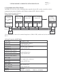
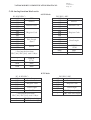
1. Communication Data Frame
VAT200 series inverter can be communication controlled by the PC or other controller with the
communication protocol, Modbus ASCII Mode & Mode RTU, RS485 or RS232.
Frame length maximum 80 bytes
1.1 Hardware Installation
Controller
(PLC / HMI or
PC )
RS-485
Interface
Slave VAT200
Address 01
Slave VAT200
Address 02
Slave VAT200
Address 03
Slave
VAT200
Address FE
Option Card
A
Option Card
B
A
Option Card
B
A
B
Option Card
A
B
Response
Request
120Ω
1/4w
120Ω
1/4w
**It is necessary to connect the terminal impedance (120Ω, 1/4W) at both ends of the communication
wire.**
1.2 Data Frame for ASCII Mode
STX(3AH)
Start Byte = 3AH
Address Hi
Communication Address:
Address Lo
2-digit ASCII Code
Function Hi
Function Code (command):
2-digit ASCII Code
Function Lo
Command Start Address
Command Start Address
Command Start Address
Command Start byte:
4-digit ASCII Code
Command Start Address
Data length
Data length
Data length
The length of the command:
4-digit ASCII Code
Data length
LRC Check Hi
LRC Check Lo
LRC Check Code:
2-digit ASCII Code
END Hi
End Byte:
END Lo
END Hi = CR(0DH)
,
END Li = LF(0AH)
File No. :
VAT200 MODBUS COMMUNICATION PROTOCOL
Version : 1.A
Page : 3
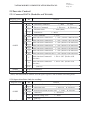
Data frame For RTU Mode
MASTER (PLC etc.) send request to SLAVE, whereas SLAVE response
to MASTER. The signal receiving is illustrated here.
The data length is varied with the command (Function).
SLAVE
Address
Function Code
DATA
CRC CHECK
** The interval should be maintained at 10ms between command signal
and request.
1.3 Slave Address
00H : Broadcast to all the drivers
01H : to the No. 01 Driver
0FH : to the No.15 Driver
10H : to the No.16 Driver
and so on...., Max to No. 254(FEH)
1.4 Function Code
03H : Read the register contents
06H : Write a WORD to register
08H : Loop test
10H : Write several data to register (complex number register write)
2.CMS (Checksum and time-out definition)
2.1 LRC
ex. ADDRESS
01H
FUNCTION
COMMAND
DATA LENGTH
----------------------Checksum =
CS(H)
CS(L)
=
=
03H
01H
00H
0AH
0FH------------ true complement
F1H
46H (ASCII)
31H (ASCII)
Signal Interval
File No. :
VAT200 MODBUS COMMUNICATION PROTOCOL
Version : 1.A
Page : 4
2.2 CRC CHECK:
CRC check code is from Slave Address to end of the data. The calculation method is illustrated as follow:
(1) Load a 16-bit register with FFFF hex (all1’s). Call this the CRC register.
(2) Exclusive OR the first 8-bit byte of the message with the low-order byte of the 16-bit CRC register,
putting the result in the CRC register.
(3) Shift the CRC register one bit to the right (toward the LSB), Zero-filling the MSB, Extract and examines
the LSB.
(4) (If the LSB was 0): Repeat Steps (3) (another shift)
(If the LSB was 1): Exclusive OR the CRC
register with the polynomial value A001 hex (1010 0000 0000 0001).
(5) Repeat Steps (3) and (4) until 8 shifts been performed. When this is done, a complete 8-bit byte will be
processed.
(6) Repeat Steps (2) through (5) for next 8-bit byte of the message, Continue doing this until all bytes have
been processed. The final content of the CRC register is the CRC value. Placing the CRC into the
message: When the 16-bit CRC (2 8-bit bytes) is transmitted in the message, the low-order byte will be
transmitted first, followed by the high-order byte, For example, if the CRC value is 1241 hex, the
CRC-16 Upper put the 41h, the CRC-16 Lower put the 12h.
CRC calculation application program
UWORD ch_sum ( UBYTE long , UBYTE *rxdbuff ) {
BYTE i = 0;
UWORD wkg = 0xFFFF;
while ( long-- ) {
wkg ^= rxdbuff++;
for ( i = 0 ; i < 8; i++ ) {
if ( wkg & 0x0001 ) {
wkg = ( wkg >> 1 ) ^ 0xa001;
}
else {
wkg = wkg >> 1;
}
}
}
return( wkg );
}
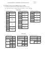
2.3 TIME-OUT (400ms) & RETRY (max. : 2 times)
PC-LINK
PC-LINK
S
400ms
S
400ms
PC-LINK
S
(When INV (PLC) time-out or detect checksum error, or INV(PLC) response exception code = checksum
error, PC-LINK retry maximum two times, and if two times after still error, then display “ERR6”)
File No. :
VAT200 MODBUS COMMUNICATION PROTOCOL
Version : 1.A
Page : 5
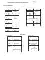
3. Command START ADDRESS
Function
03
Function Description
Ladder page1 read
Ladder page2 read
Ladder page3 read
Ladder page4 read
Ladder page5 read
Timer1 Function read
Timer2 Function read
Timer3 Function read
Timer4 Function read
Timer5 Function read
Timer6 Function read
Timer7 Function read
Timer8 Function read
Counter1 Function read
Counter2 Function read
Counter3 Function read
Counter4 Function read
Encoder1 Function read
Encoder2 Function read
Encoder3 Function read
Encoder4 Function read
Analog1 Function read
Analog2 Function read
Analog3 Function read
Analog4 Function read
Control function read
Contro2 function read
Contro3 function read
Contro4 function read
Contro5 function read
Contro6 function read
Contro7 function read
Contro8 function read
All Coil status read
Command
Data length
Start Address
200H
20AH
214H
21EH
228H
264H
269H
26EH
273H
278H
27DH
282H
287H
28CH
290H
294H
298H
2ACH
2B1H
2B6H
2BBH
2C0H
2C3H
2C6H
2C9H
2CCH
2D2H
2D8H
2DEH
2E4H
2EAH
2F0H
2F6H
2FCH~303H
(WORD)
0AH
0AH
0AH
0AH
0AH
05H
05H
05H
05H
05H
05H
05H
05H
04H
04H
04H
04H
05H
05H
05H
05H
03H
03H
03H
03H
06H
06H
06H
06H
06H
06H
06H
06H
08H
File No. :
VAT200 MODBUS COMMUNICATION PROTOCOL
Version : 1.A
Page : 6
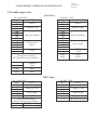
Function
10
06
Function Description
Ladder page1 write
Ladder page2 write
Ladder page3 write
Ladder page4 write
Ladder page5 write
Timer1 Function write
Timer2 Function write
Timer3 Function write
Timer4 Function write
Timer5 Function write
Timer6 Function write
Timer7 Function write
Timer8 Function write
Counter1 Function write
Counter2 Function write
Counter3 Function write
Counter4 Function write
Encoder1 Function write
Encoder2 Function write
Encoder3 Function write
Encoder4 Function write
Analog1 Function write
Analog2 Function write
Analog3 Function write
Analog4 Function write
Control function write
Contro2 function write
Contro3 function write
Contro4 function write
Contro5 function write
Contro6 function write
Contro7 function write
Contro8 function write
Coil status write
RUN & Stop(PLC)
All memory clear
(Clear PLC Memory)
PASSWORD
Command
Start Address
Data length
(WORD)
200H
20AH
214H
21EH
228H
264H
269H
26EH
273H
278H
27DH
282H
287H
28CH
290H
294H
298H
2ACH
2B1H
2B6H
2BBH
2C0H
2C3H
2C6H
2C9H
2CCH
2D2H
2D8H
2DEH
2E4H
2EAH
2F0H
2F6H
2FCH
330H
0AH
0AH
0AH
0AH
0AH
04H
04H
04H
04H
04H
04H
04H
04H
03H
03H
03H
03H
04H
04H
04H
04H
03H
03H
03H
03H
06H
06H
06H
06H
06H
06H
06H
06H
01H
1
331H
1
332H
1
Note: ‘Write Ladder page write’ and ‘Clear all memory’ are not available under PLC running
mode.
File No. :
VAT200 MODBUS COMMUNICATION PROTOCOL
Version : 1.A
Page : 7
4. Exception Code
ASCII Mode
STX
Address
RTU Mode
‘:’
SLAVE Address
02H
‘0’
Function
83H
‘1’
Exception code
52H
‘8’
Function
CRC-16
‘6’
Exception
code
High
C0H
Low
CDH
‘5’
‘1’
LRC Check
‘2’
‘8’
‘CR’
END
‘LF’
Under communication linking, the driver responses the Exception Code and send Function Code AND
80H to main system if there is error happened.
Exception Code
Description
51
Function Code Error
52
Register Encoding Error
53
Data Quantity Error
54
DATA Setting Error
55
Write Mode Error
File No. :
VAT200 MODBUS COMMUNICATION PROTOCOL
Version : 1.A
Page : 8
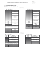
5. Command Start Address Description
5.1 Ladder (* ) page read
ASCII Mode
PC INV (PLC)
3AH
30H
31H
30H
33H
INV (PLC)PC
STX
3AH
30H
Address
30H
30H
Function Code
*Register
Number
?
Data length
34H
(Byte)
?
Data Length
41H
?
31H
Send out the data from
PLC[0]~PLC[19], total 40 Byte
30H
30H
Function Code
33H
30H
30H
Address
31H
30H
32H
STX
?
CHECK
SUM,
0DH
END
0AH
END
CHECK SUM,
0DH
END
0AH
END
RTU Mode
PC INV(PLC)
INV(PLC)PC
01H
Address
01H
Address
03H
Function Code
03H
Function Code
14H
Data length
02H
00H
00H
0AH
* Register Number
Data length
CRC High order digits
CRC Low order digits
Sent out the data from PLC[0]~PLC[19],
total 20 Byte
?
CRC High order digits
?
CRC Low order digits
File No. :
VAT200 MODBUS COMMUNICATION PROTOCOL
Version : 1.A
Page : 9
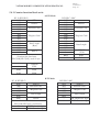
5.2 Function block read
5.2.1 Timer function block read
ASCII Mode
PC INV (PLC)
INV (PLC)PC
3AH
STX
30H
3AH
30H
Address
31H
30H
30H
*Register
Number
36H
Function Code
33H
30H
32H
Address
31H
Function Code
33H
STX
30H
Data length
41H
(Byte)
*Send out the data from
PLC[200]~PLC[209], total 20 Byte
34H
30H
?
30H
Data Length
30H
35H
?
?
CHECK
SUM,
0DH
END
0AH
END
CHECK SUM,
?
0DH
END
0AH
END
RTU Mode
PC INV (PLC)
INV(PLC)PC
01H
Address
01H
Address
03H
Function Code
03H
Function Code
0AH
Data Length
02H
64H
00H
05H
*Register Code
Data Length
CRC High order digit
CRC Low order digit
*Send out the data from PLC[200]~PLC[209],
total 10 Byte
?
CRC High order digit
?
CRC Low order digit
File No. :
VAT200 MODBUS COMMUNICATION PROTOCOL
Version : 1.A
Page : 10
5.2.2 Counter function block read
ASCII Mode
PC INV (PLC)
3AH
INV (PLC) PC
STX
30H
Address
31H
30H
STX
30H
STX
Address
31H
30H
Function Code
33H
3AH
33H
30H
30H
*Register
Number
32H
38H
Data Length
(Byte)
38H
*send out the data from
PLC[280]~PLC[287], total 16 Byte
43H
30H
30H
Data Length
30H
34H
?
?
CHECK
?
SUM,
0DH
END
0AH
END
CHECK SUM,
?
0DH
END
0AH
END
RTU Mode
PC INV(PLC)
INV(PLC)PC
01H
Address
01H
Address
03H
Function Code
03H
Function Code
02H
*Register Code
08H
Data Length
8CH
00H
Data Length
04H
CRC High order digit
CRC Low order digit
*Send out the data from
PLC[280]~PLC[287], total 8 Byte
?
CRC High order digit
?
CRC Low order digit
File No. :
VAT200 MODBUS COMMUNICATION PROTOCOL
Version : 1.A
Page : 11
5.2.3 Encoder function block read
ASCII Mode
PC INV(PLC)
3AH
INV(PLC) PC
STX
30H
3AH
30H
Address
31H
30H
Address
31H
30H
Function Code
33H
STX
Function Code
33H
30H
30H
*Register
Number
32H
41H
Data Length
(Byte)
41H
*Send out the data from
PLC[344]~PLC[353], total 20 Byte
43H
30H
30H
Data Length
30H
35H
?
?
CHECK
?
SUM,
0DH
END
0AH
END
CHECK SUM,
?
0DH
END
0AH
END
RTU Mode
PC INV(PLC)
INV(PLC)PC
01H
Address
01H
Address
03H
Function Code
03H
Function Code
02H
*Register Code
0AH
Data Length
ACH
00H
Data Length
05H
CRC High order digit
CRC Low order digit
*Send out the data from
PLC[344]~PLC[353], total 10 Byte
?
CRC High order digit
?
CRC Low order digit
File No. :
VAT200 MODBUS COMMUNICATION PROTOCOL
Version : 1.A
Page : 12
5.2.4 Analog function block read
ASCII Mode
PC INV(PLC)
3AH
INV(PLC) PC
STX
30H
3AH
30H
Address
31H
30H
Address
31H
30H
Function Code
33H
STX
Function Code
33H
30H
30H
*Register
Number
32H
43H
Data Length
(Byte)
36H
*Send out the data from
PLC[384]~PLC[389], total 12 Byte
30H
30H
30H
Data Length
30H
33H
?
?
CHECK
?
SUM,
0DH
END
0AH
END
CHECK SUM,
?
0DH
END
0AH
END
RTU Mode
PC INV(PLC)
INV(PLC)PC
01H
Address
01H
Address
03H
Function Code
03H
Function Code
06H
Data Length
02H
C0H
*Register Code
00H
Data Length
03H
**Send out the data from
PLC[384]~PLC[389], total 12
Byte
?
CRC High order digit
CRC Low order digit
?
CRC High order
digit
CRC Low order
digit
File No. :
VAT200 MODBUS COMMUNICATION PROTOCOL
Version : 1.A
Page : 13
5.2.5 Control function block read
ASCII Mode
INV(PLC) PC
PC INV(PLC)
3AH
STX
30H
3AH
30H
Address
31H
30H
Address
31H
30H
Function Code
33H
STX
Function Code
33H
30H
30H
*Register
Number
32H
43H
Data Length
(Byte)
43H
*Send out the data from
PLC[408]~PLC[419], total 24 Byte
43H
30H
30H
Data Length
30H
36H
?
?
CHECK
?
SUM,
0DH
END
0AH
END
CHECK SUM,
?
0DH
END
0AH
END
RTU Mode
PC INV(PLC)
INV(PLC)PC
01H
Address
01H
Address
03H
Function Code
03H
Function Code
02H
*Register Code
0CH
Data Length
CCH
00H
Data Length
06H
CRC High order digit
CRC Low order digit
**Send out the data from
PLC[408]~PLC[419], total 12 Byte
?
CRC High order digit
?
CRC Low order digit
File No. :
VAT200 MODBUS COMMUNICATION PROTOCOL
Version : 1.A
Page : 14
5.2.6 Coil status read
ASCII Mode
PC INV (PLC)
3AH
30H
31H
30H
33H
INV(PLC) PC
STX
3AH
30H
Address
46H
30H
Function Code
31H
*Register
Number
*Send out the data from
PLC[504]~PLC[519], total 32 Byte
Data Length
38H
?
Data Length
(Byte)
30H
30H
30H
Function Code
33H
43H
30H
Address
31H
30H
32H
STX
?
CHECK
?
SUM,
0DH
END
0AH
END
CHECK SUM,
?
0DH
END
0AH
END
RTU Mode
PC INV(PLC)
INV(PLC)PC
01H
Address
01H
Address
03H
Function Code
03H
Function Code
02H
*Register Code
10H
Data Length
FCH
00H
Data Length
08H
*Send out the data
from
PLC[504]~PLC[519],
total 16 Byte
?
CRC High order digit
CRC Low order digit
?
CRC High order
digit
CRC Low order
digit
File No. :
VAT200 MODBUS COMMUNICATION PROTOCOL
Version : 1.A
Page : 15
5.3 Ladder page write
ASCII Mode
PC INV(PLC)
3AH
STX
30H
Address
31H
31H
Function Code
30H
30H
32H
*Register Number
30H
30H
30H
30H
Data Length
(Byte)
30H
41H
31H
DATA
34H
INV(PLC) PC
3AH
30H
Address
31H
30H
Function Code
33H
30H
32H
*Register Number
30H
30H
30H
30H
Data Length
30H
41H
?
CHECK
SUM,
?
0DH
END
*Send out the data from
PLC[0]~PLC[19], total 40 Byte
?
?
CHECK
SUM,
0DH
END
0AH
END
0AH
END
RTU Mode
PC INV(PLC)
01H
Address
10H
Function Code
02H
*Register Code
00H
00H
Data Length
0AH
14H
DATA
*end out the data from
PLC[0]~PLC[19], total 20 Byte
CRC High order digit
CRC Low order digit
INV(PLC)PC
01H
Address
03H
Function Code
02H
* Register Code
00H
00H
Data Length
0AH
?
CRC High order digit
?
CRC Low order digit
File No. :
VAT200 MODBUS COMMUNICATION PROTOCOL
Version : 1.A
Page : 16
5.4 Function block write
5.4.1 Timer function block write
ASCII Mode
PC INV(PLC)
3AH
STX
30H
Address
31H
31H
Function Code
30H
30H
32H
*Register
Number
36H
34H
30H
30H
Data Length
(Byte)
30H
34H
30H
DATA
38H
INV(PLC) PC
3AH
30H
Address
31H
31H
Function Code
30H
30H
32H
* Register
Number
36H
34H
30H
30H
Data Length
30H
34H
?
CHECK
SUM,
?
0DH
END
*Send out the data from
PLC[200]~PLC[207], total 16 Byte
?
?
0DH
0AH
0AH
0AH
END
END
CHECK
SUM,
END
END
RTU Mode
PC INV (PLC)
01H
Address
10H
Function Code
02H
*Register Code
64H
00H
Data Length
04H
08H
DATA
*Send out the data from
PLC[200]~PLC[207], total 8 Byte
?
?
CRC High order digits
CRC Low order digits
INV(PLC)PC
01H
Address
10H
Function Code
02H
*Register Code
64H
00H
Data Length
04H
?
CRC High order digits
?
CRC Low order digits
File No. :
VAT200 MODBUS COMMUNICATION PROTOCOL
Version : 1.A
Page : 17
5.4.2 Counter function block write
ASCII Mode
PC INV(PLC)
3AH
STX
30H
Address
31H
31H
Function Code
30H
30H
32H
*Register Code
38H
43H
30H
30H
Data Length
(Byte)
30H
33H
30H
DATA
36H
INV(PLC) PC
3AH
30H
Address
31H
30H
Function Code
33H
30H
32H
*Register Code
38H
43H
30H
30H
Data Length
30H
33H
?
CHECK
SUM,
?
0DH
END
*Send out the data from
PLC[280]~PLC[285], total 12 byte
?
?
CHECK
SUM,
0DH
0AH
END
END
0AH
END
RTU Mode
PC INV(PLC)
01H
10H
02H
8CH
00H
03H
06H
Address
Function Code
*Register Code
Data Length
DATA
*Send out the data from
PLC[280]~PLC[285], total 6 Byte
?
?
CRC High order digits
CRC Low order digits
INV(PLC)PC
01H
Address
10H
Function Code
02H
*Register Code
8CH
00H
Data Length
03H
?
CRC High order digits
?
CRC Low order digits
File No. :
VAT200 MODBUS COMMUNICATION PROTOCOL
Version : 1.A
Page : 18
5.4.3 Encoder function block write
ASCII Mode
PC INV(PLC)
3AH
30H
31H
31H
30H
30H
32H
41H
43H
30H
30H
30H
34H
30H
38H
INV(PLC) PC
3AH
30H
Address
31H
30H
Function Code
33H
30H
32H
*Register Code
41H
43H
30H
30H
Data Length
30H
34H
?
CHECK
SUM,
?
STX
Address
Function Code
*Register Code
Data Length
(Byte)
DATA
*Send out the data from
PLC[344]~PLC[353], total 16 Byte
?
0DH
END
0AH
END
CHECK
?
SUM,
0DH
END
0AH
END
RTU Mode
PC INV(PLC)
01H
10H
02H
ACH
00H
04H
08H
Address
Function Code
*Register Code
Data Length
DATA
* Send out the data from
PLC[344]~PLC[353], total 8 Byte
?
?
CRC High order digits
CRC Low order digits
INV(PLC)PC
01H
Address
10H
Function Code
02H
*Register Code
ACH
00H
Data Length
04H
?
CRC High order digits
?
CRC Low order digits
File No. :
VAT200 MODBUS COMMUNICATION PROTOCOL
Version : 1.A
Page : 19
5.4.4 Analog function block write
ASCII Mode
INV(PLC) PC
3AH
30H
Address
31H
30H
Function Code
33H
30H
32H
*Register Code
43H
30H
30H
30H
Data Length
30H
33H
?
CHECK
SUM,
?
0DH
END
PC INV(PLC)
3AH
STX
30H
Address
31H
31H
Function Code
30H
30H
32H
*Register Code
43H
30H
30H
30H
Data Length
(Byte)
30H
33H
30H
DATA
36H
* Send out the data from
PLC[384]~PLC[389], total 12 Byte
?
CHECK
?
SUM,
0DH
END
0AH
END
0AH
END
RTU Mode
PC INV(PLC)
01H
Address
10H
Function Code
02H
*Register Code
C0H
00H
Data Length
03H
06H
DATA
* Send out the data from
PLC[384]~PLC[389], total 12 Byte
?
?
CRC High order digits
CRC Low order digits
INV(PLC)PC
01H
Address
10H
Function Code
02H
*Register Code
C0H
00H
Data Length
03H
?
CRC High order digits
?
CRC Low order digits
File No. :
VAT200 MODBUS COMMUNICATION PROTOCOL
Version : 1.A
Page : 20
5.4.5 Control function block write
ASCII Mode
INV(PLC) PC
3AH
30H
Address
31H
30H
Function Code
33H
30H
32H
*Register Code
43H
43H
30H
30H
Data Length
30H
36H
?
CHECK
SUM,
?
0DH
END
PC INV(PLC)
3AH
STX
30H
Address
31H
31H
Function Code
30H
30H
32H
*Register Code
43H
43H
30H
30H
Data Length
(Byte)
30H
36H
30H
DATA
43H
* Send out the data from
PLC[408]~PLC[419], total 24 Byte
?
CHECK
?
SUM,
0DH
END
0AH
END
0AH
END
RTU Mode
PC INV(PLC)
01H
Address
10H
Function Code
02H
*Register Code
CCH
00H
Data Length
06H
0CH
DATA
*Send out the data from
PLC[408]~PLC[419], total 12 Byte
?
?
CRC High order digits
CRC Low order digits
INV(PLC)PC
01H
Address
10H
Function Code
02H
*Register Code
CCH
00H
Data Length
03H
?
CRC High order digits
?
CRC Low order digits
File No. :
VAT200 MODBUS COMMUNICATION PROTOCOL
Version : 1.A
Page : 21
5.4.6 Coil status write
ASCII Mode
PC INV(PLC)
3AH
30H
31H
30H
36H
30H
32H
46H
43H
*Data to be written to
*Data to be written to
*Data to be written to
*Data to be written to
?
?
0DH
0AH
INV(PLCPC
3AH
STX
30H
Address
31H
30H
Function Code
36H
30H
32H
* Register Code
46H
43H
STX
Address
Function Code
* Register Code
16-Bit data comprising
of 4 ASCII codes
CHECK
SUM
END
END
*Data to be written to
*Data to be written to 16-Bit data comprising
of 4 ASCII codes
*Data to be written to
*Data to be written to
?
CHECK
SUM
?
0DH
END
0AH
END
RTU Mode
01H
06H
02H
FCH
*Data to be written to
*Data to be written to
?
?
note:
Write to
Coil
INPUT
TIMER
COUNTER
Aux. coil
Control coil
ANALOG
ENCODER
OUTPUT
Address
Function Code
Register Code
16-Bit data
CRC High order digits
CRC Low order digits
Start code
02FDH
02FEH
02FFH
0300H
0301H
0302H
0302H
0303H
01H
06H
02H
FCH
*Data to be written to
*Data to be written to
?
?
Address
Function Code
Register Code
16-Bit data
CRC High order digits
CRC Low order digits
File No. :
VAT200 MODBUS COMMUNICATION PROTOCOL
Version : 1.A
Page : 22
5.5 Inverter Control
5.5.1 Command DATA (Readable and Writable)
Register Code
Content
Ready-to-use
Operation Signal
0100H
Bit
0101H
0
Operation Command
1
Reverse Command
2
External Fault
3
Fault Reset
4
Log Command
1 : Reverse
0 : Stop
0 : Forward
1 : Fault (EFO)
1 : Reset
1 : Log
5
Multi function Command S1
1 :“ON” (Define 5-00 Function )
6
Multi function Command S2
1 :“ON” (Define 5-01 Function)
7
Multi function Command S3
1 :“ON”(Define 5-02 Function)
8
Multi function Command S4
1 :“ON”(Define 5-03 Function)
9
Multi function Command S5
1 :“ON”(Define 5-04 Function)
A
Multi function Command S6
1 :“ON”(Define 5-05 Function)
B
Multi function Command AIN 1 :“ON”(Define 5-06 Function)
C
D
Multi function Command 1
1 : R1A “ON” (Define 8-02
Function)
Multi function Command 2
Function)
E-F
0102H
1 : Run
1 : R2A “ON” (Define 8-03
(unused)
Frequency Command
0103~011FH
Ready-to-use
(Note) The unused Bit is defined as 0, the spare register is not available for writing Data.
5.5.2 Supervision Data (Only for reading)
0120H
Bit
State Signal
Register code
Content
0
Operation State
1 : Run
1
Direction State
1 : Reverse
2
Inverter operation prepare state
3
Abnormal
1 : Abnormal
4
DATA setting error
1 : Error
5-F
(unused)
(Note) Please define the unused Bit as 0.
1 : ready
0 : Stop
0 : Forward
0 : unready
File No. :
VAT200 MODBUS COMMUNICATION PROTOCOL
Version : 1.A
Page : 23
Register code
Content
The inverter is normal
Program abnormal(CPF)
24 Under voltage during running ( LV-C )
EEPROM abnormal (EPR)
25 ~ 28 (unused)
Over voltage ( OV )
29
(Err8)
Under voltage( LV )
30 Stop at 0 Hz( STP0 )
Inverter over heat ( OH )
31 Direct start disable ( STP1 )
06 ~ 09 (unused)
32 Control panel emergency stop ( STP2 )
Over current during decelerating
10
33 Emergency stop ( E.S )
( OC-D )
Over current during accelerating
34 External BB( bb )
11
( OC-A )
Over current at constant speed
12
35 Auto testing error( ATER )
( OC-C )
Over voltage at constant speed /
13
36 PID feedback signal loss( PDER )
decelerating ( OV-C )
Inverter over heat at constant speed
14
37 Communication error(EFO)
( OH-C )
15 Inverter over speed ( OVSP )
38 Encoder signal loss ( ECER ) *1
16 CPU interrupted ( CTER )
39 Analog converting error(Err4)
17
(OC_S)
40 Parameter locked( LOC )
41 Keypad operation error ( Err1 )
18~19 (Unused)
20 Over current at stop( OC )
42 Parameter setting error ( Err2 )
43 Modifying the parameter in
21 Motor over load (OL1)
communication( Err5 )
22 Inverter over load ( OL2 )
44 Communication failure ( Err6 )
23 Over torque detected ( OL3 )
45 Parameter setting error ( Err7 )
0
Terminal S1
1 : OFF
1
Terminal S2
1 : OFF
2
Terminal S3
1 : OFF
3
Terminal S4
1 : OFF
4
Terminal S5
1 : OFF
5
Terminal S6
1 : OFF
Terminal AIN
1 : OFF
6
(unused)
7-9
A Multifunction output 1(RELAY1) (1 : R1A ON 0 : R1A OFF)
B Multifunction output 2(RELAY2) (1 : R2A ON 0 : R2A OFF)
C~F (Unused)
Frequency command
Output frequency
Output voltage command (1/1V)
Output DC voltage command (1/1V)
Terminal
output
0122H
Sequent input value
0121H
Error content
00
01
02
03
04
05
0123H
0124H
0125H
0126H
(Note) Please define the unused Bit as 0.
File No. :
VAT200 MODBUS COMMUNICATION PROTOCOL
Version : 1.A
Page : 24
Register Code
Content
0127H
Output current (10/1A)
0128H
Reserved
0129H
Output torque
012AH
PID Feedback value (100% / Max output frequency, 10/1% )
012BH
PID input value (100% / Max output frequency, 10/1% , sign
attached)
012CH
TM2 AIN input value (1024 / 10V) *1
012DH
TM2 AV2 input value (1024 / 10V) *1
012EH-012FH
Ready-to-use
(Note:) The ready-to-use register is not available for the data write.
File No. :
VAT200 MODBUS COMMUNICATION PROTOCOL
Version : 1.A
Page : 25
5.5.3 Read the data in the holding register [03H]
Continuously read the data in the register from the specified address.
(e.g.) Read the frequency command from the SLAVE 1, inverter VAT200.
Command Signal
3AH
STX
SLAVE
30H
Address
31H
30H
Function
Code
33H
30H
Start to
31H
encode
32H
33H
30H
30H
Data
30H
31H
?
LRC CHECK
?
0DH
END
0AH
ASCII Mode
Respond signal (Normally)
3AH
STX
SLAVE
30H
Address
31H
30H
Function
Code
33H
30H
DATA
Quantity
32H
31H
37H
Initial holding
register
37H
30H
?
LRC CHECK
?
0DH
END
0AH
RTU Mode
Respond signal (Normally)
Command Signal
Respond signal (Error)
3AH
STX
SLAVE
30H
Address
32H
38H
Function
Code
33H
35H
Exception
Code
32H
0DH
END
0AH
Respond signal (Error)
SLAVE Address
01 H
SLAVE Address
01H
SLAVE Address
02H
Function Code
03H
Function Code
03H
Function Code
83H
High
01H
02H
Exception Code
52H
Low
23H
DATA
Initial
holding
register
Start to
encode
Data
quantity
CRC-16
High
00H
Low
01H
High
74H
Low
3CH
CRC-16
High
17H
Low
70H
High
AFH
Low
82H
CRC-16
High
C0H
Low
CDH
File No. :
VAT200 MODBUS COMMUNICATION PROTOCOL
Version : 1.A
Page : 26
5.5.4 LOOP BACK CHECK [08H]
The check code checking the transmission of the signal between MASTER and SLAVE could be
discretionary.
Command Signal
3AH
STX
SLAVE
30H
Address
31H
30H
Function
Code
38H
30H
30H
Check Code
30H
30H
41H
35H
33H
37H
?
?
0DH
0AH
ASCII Mode
Respond signal (Normally)
3AH
STX
SLAVE
30H
Address
31H
30H
Function
Code
38H
30H
30H
Check Code
30H
30H
41H
DATA
LRC CHECK
END
35H
33H
37H
?
?
0DH
0AH
DATA
LRC CHECK
END
RTU Mode
Respond signal (Normally)
Command Signal
Respond signal (Error)
3AH
STX
SLAVE
30H
Address
31H
38H
Function
Code
38H
32H
Exception
Code
30H
?
LRC CHEC
?
0DH
END
0AH
Respond signal (Error)
SLAVE Address
01 H
SLAVE Address
01H
SLAVE Address
01H
Function Code
08H
Function Code
08H
Function Code
88H
High
00H
Exception Code
20H
Low
00H
High
A5H
Low
37H
High
DAH
Low
8DH
Check
Code
DATA
CRC-16
High
00H
Low
00H
High
A5H
Low
37H
High DAH
Low
8DH
Check
Code
DATA
CRC-16
CRC-16
High
47H
Low
D8H
File No. :
VAT200 MODBUS COMMUNICATION PROTOCOL
Version : 1.A
Page : 27
5.5.5Write to the holding register [06H]
Write the specified data to the holding register from the defined address.
(e.g.) write the frequency command 60.0Hz from PLC to SLAVE 1, inverter VAT200.
ASCII Mode
Command Signal
3AH
STX
30H
SLAVE
Address
31H
Function
30H
Code
36H
30H
31H
Start to
encode
30H
32H
31H
37H
37H
30H
?
?
0DH
0AH
Respond signal (Normally)
3AH
STX
30H
SLAVE
Address
31H
Function
30H
Code
36H
30H
31H
Start to
encode
30H
32H
31H
DATA
LRC CHECK
END
37H
37H
30H
?
?
0DH
0AH
Respond signal (Error)
3AH
STX
30H
SLAVE
Address
31H
Function
38H
Code
36H
35H
Exception
Code
32H
?
LRC CHECK
?
0DH
END
0AH
DATA
LRC CHECK
END
RTU Mode
Command Signal
Respond signal (Normally)
Respond signal (Error)
SLAVE Address
01 H
SLAVE Address
01H
SLAVE Address
01H
Function Code
06H
Function Code
06H
Function Code
86H
Exception Code
52H
Start to
High
01H
Start to
High
01H
encode
Low
02H
encode
Low
02H
Data
High
17H
Data
High
17H
Quantity
Low
70H
Quantity
Low
70H
High
27H
High
27H
Low
E2H
Low
E2H
CRC-16
CRC-16
CRC-16
High
C3H
Low
9DH
File No. :
VAT200 MODBUS COMMUNICATION PROTOCOL
Version : 1.A
Page : 28
5.5.6 Write complex Number holding register [10H]
From the defined code, write the respective specified data to the holding registers.
e.g. Input the frequency command ‘Running forward at 60.0Hz’ into the SLAVE 1 V2 from PLC.
Command Signal
3AH
STX
30H
SLAVE
Address
31H
31H
Function
Code
30H
30H
31H
Start coding
30H
31H
30H
30H
30H
32H
30H
34H
30H
30H
30H
31H
31H
37H
37H
30H
?
?
0DH
0AH
ASCII Mode
Respond signal (Normally)
3AH
STX
30H
SLAVE
Address
31H
31H
Function
Code
30H
30H
31H
Start coding
30H
31H
30H
Data quantity
DATA *
Primary
DATA
30H
30H
32H
?
?
0DH
0AH
Data quantity
LRC CHECK
Secondary
DATA
LRC CHECK
END
* DATA Quantity is equal to the Number multiply 2.
END
Respond signal (Error)
3AH
STX
30H
SLAVE
Address
31H
39H
Function
Code
30H
Exception
35H
Code
32H
?
LRC CHECK
?
0DH
END
0AH
File No. :
VAT200 MODBUS COMMUNICATION PROTOCOL
Version : 1.A
Page : 29
Command Signal
SLAVE Address
Function Code
Start to High
encode Low
Data
High
quantity Low
DATA number *
Primary High
DATA Low
Secondary High
DATA Low
High
CRC-16
Low
01 H
10H
01H
01H
00H
02H
04H
00H
01H
17H
70H
60H
27H
RTU Mode
Respond signal (Normally)
SLAVE Address 01H
Function Code
10H
Start to High 01H
encode Low 01H
Data
High 00H
quantity Low 02H
High 11H
CRC-16
Low F4H
* ‘DATA number’ is equal to the ‘data quantity’ multiply 2.
Respond signal (Error)
SLAVE Address
01H
Function Code
90H
Exception Code
52H
High
CDH
CRC-16
Low
FDH
File No. :
VAT200 MODBUS COMMUNICATION PROTOCOL
Version : 1.A
Page : 30
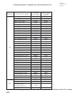
Comparison list between parameter and register (as for the parameter description, please refer to the
parameter function list)
Register
Code
0000H
0001H
0002H
0003H
0004H
0005H
0006H
0007H
0008H
0009H
000AH
000BH
000CH
000DH
000EH
000FH
0010H
0011H
0012H
0013H
0014H
0015H
0016H
0017H
0018H
0019H
001AH
001BH
001CH
001DH
001EH
001FH
0020H
0021H
0022H
FUNCTION
BLOCK
0-0
0-1
0-2
0-3
0-4
0-5
0-6
0-7
0-8
1-0
1-1
1-2
1-3
1-4
1-5
1-6
1-7
2-0
2-1
2-2
2-3
2-5
2-6
2-7
3-0
3-1
3-2
3-3
3-4
3-5
3-6
3-7
3-8
3-9
3-10
Register Code
0023H
0024H
0025H
0026H
0027H
0028H
0029H
002AH
002BH
002CH
002DH
002EH
002FH
0030H
0031H
0032H
0033H
0034H
0035H
0036H
0037H
0038H
0039H
003AH
003BH
003CH
003DH
003EH
003FH
0040H
0041H
0042H
0043H
0044H
0045H
FUNCTION
BLOCK
3-11
3-12
3-13
3-14
3-15
3-16
3-17
3-18
3-19
3-20
3-21
3-22
4-0
4-1
4-2
4-3
4-4
4-5
5-0
5-1
5-2
5-3
5-4
5-5
5-6
5-7
~
6-0
6-1
6-2
6-3
6-4
6-5
6-6
6-7
File No. :
VAT200 MODBUS COMMUNICATION PROTOCOL
Version : 1.A
Page : 31
Register
Code
0046H
0047H
0048H
0049H
004AH
004BH
004CH
004DH
004EH
004FH
0050H
0051H
0052H
0053H
0054H
0055H
0056H
0057H
0058H
0059H
005AH
005BH
005CH
005DH
005EH
005FH
0060H
0061H
0062H
0063H
0064H
0065H
0066H
0067H
0068H
FUNCTION
BLOCK
6-8
7-0
7-1
7-2
7-3
7-4
7-5
8-0
8-1
8-2
8-3
8-4
8-5
9-0
9-1
9-2
9-3
9-4
9-5
9-6
9-7
9-8
9-9
9-10
9-11
9-12
9-13
9-14
9-15
10-0
10-1
10-2
10-3
10-4
10-5
Register Code
0069H
006AH
006BH
006CH
006DH
006EH
006FH
0070H
0071H
0072H
0073H
0074H
0075H
0076H
0077H
0078H
0079H
007AH
007BH
007CH
007DH
007EH
007FH
0080H
0081H
0082H
0083H
0084H
0085H
0086H
0087H
0088H
0089H
008AH
008BH
FUNCTION
BLOCK
10-6
10-7
10-8
10-9
11-0
11-1
11-2
11-3
11-4
11-5
11-6
11-7
12-0
12-1
12-2
12-3
12-4
12-5
12-6
13-0
13-1
13-2
13-3
13-4
14-0
14-1
14-2
14-3
14-4
15-0
15-1
15-2
15-3
15-4
15-5
File No. :
VAT200 MODBUS COMMUNICATION PROTOCOL
Version : 1.A
Page : 32
Register
Code
008CH
008DH
008EH
008FH
0090H
0091H
0092H
0093H
0094H
0095H
0096H
0097H
0098H
0099H
009AH
009BH
009CH
009DH
009EH
009FH
00A0H
00A1H
00A2H
00A3H
00A4H
00A5H
00A6H
00A7H
00A8H
00A9H
00AAH
00ABH
00ACH
00ADH
00AEH
FUNCTION
BLOCK
15-6
3-23
3-24
3-25
3-26
3-27
3-28
3-29
5-8
~
2-4
2-8
~
~
~
~
~
~
~
~
~
~
~
~
~
~
~
~
~
~
~
~
Register Code
00AFH
00B0H
00B1H
00B2H
00B3H
00B4H
00B5H
00B6H
00B7H
00B8H
00B9H
00BAH
00BBH
00BCH
00BDH
00BEH
00BFH
00C0H
00C1H
00C2H
00C3H
00C4H
00C5H
00C6H
00C7H
00C8H
00C9H
00CAH
00CBH
00CCH
00CDH
00CEH
00CFH
00D0H
00D1H
FUNCTION
BLOCK
~
~
~
~
~
~
~
~
~
~
~
~
~
~
~
~
~
~
~
~
~
~
~
~
~
~
~
~
~
~
~
~
~
~
~
File No. :
VAT200 MODBUS COMMUNICATION PROTOCOL
Version : 1.A
Page : 33
Register
Code
00D2H
00D3H
00D4H
00D5H
00D6H
00D7H
00D8H
00D9H
00DAH
00DBH
00DCH
00DDH
00DEH
00DFH
00E0H
00E1H
00E2H
00E3H
00E4H
00E5H
00E6H
00E7H
00E8H
00E9H
00EAH
00EBH
00ECH
00EDH
00EEH
00EFH
00F0H
00F1H
00F2H
00F3H
00F4H
00F5H
00F6H
FUNCTION
BLOCK
~
~
~
~
~
~
~
~
~
~
~
~
~
~
~
~
~
~
~
~
~
~
~
~
~
~
~
~
~
~
~
~
~
~
~
~
~
Register Code
00F7H
00F8H
00F9H
00FAH
00FBH
00FCH
00FDH
00FEH
00FFH
~
FUNCTION
BLOCK
~
~
~
~
~
~
~
~
~
~
Cover U200ABU430 User Manual 3-06-2005
GE Consumer & Industrial
Power Protection
GE Consumer & Industrial
GE POWER CONTROLS
Hornhouse Lane
Knowsley Industrial Park
Liverpool L33 7YQ
U200ABU430 - User Manual
GE POWER CONTROLS IBERICA
Marqués de Comillas 1
E-08225 Terrassa
GE CONSUMER & INDUSTRIAL GmbH
Sachsenring 83
D-50677 Köln
GE POWER CONTROLS FRANCE
7, Rue Nicolas Robert BP32
ZI La Garenne
F-93601 Aulnay sous Bois Cédex
GE POWER CONTROLS ITALIA
Via Tortona 35
I-20144 Milano
U200ABU430
Dynamic Braking Unit for VAT200 AC Drive Series
GE POWER CONTROLS BELGIUM
Nieuwevaart 51
B-9000 Gent
GE imagination at work
GE imagination at work
Ref. C/4505BU/E 5.0 Ed. 06/05
© Copyright GE Power Controls 2005