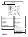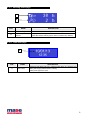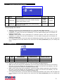
1
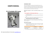
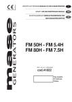
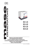
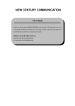
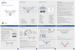
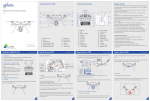
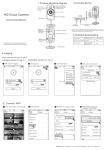
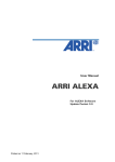
CBU
User manual
For generating group 3000 / 3600 rpm
rev.0 A.A. 20/07/2014
cod. 43274
1
INDICE
Section 1 – Electrical connection
1- 1 General chart....................................................................................................................................................................... 3
Section 2 – Descrizione apparecchiatura
2- 1 Operating modes................................................................................................................................................................. 4
2- 2 Features ............................................................................................................................................................................... 4
2- 3 Display page........................................................................................................................................................................ 5
2- 3.1 Stand-by page............................................................................................................................................................. 5
2- 3.2 Battery page ............................................................................................................................................................... 6
2- 3.3 Working hours page ................................................................................................................................................... 6
2- 3.4 Date hour page ........................................................................................................................................................... 6
Section 3 – User menu
3- 1 Access to user setup .......................................................................................................................................................... 7
3- 2 User Setup ........................................................................................................................................................................... 8
3- 2.1 Language and contrast setup...................................................................................................................................... 9
3- 2.2 Calendar setup............................................................................................................................................................ 9
3- 2.3 Events list.................................................................................................................................................................. 10
3- 2.4 Alarm chart................................................................................................................................................................ 11
Section 4 – Quick reference
4- 1 Quick reference................................................................................................................................................................. 12
2
Section 1
Electrical connection
1- 1 General chart
CN1
1 – START relay
2 – Positive battery
3 – Positive battery
4 – Common START relay, Stop solenoid, glow plug,
insulated poles
5 – Negative battery
6 – Negative battery
CN2
1 – Glow plug relay
2 – Stop solenoid relay
3 – Insulated poles relay
4 – Positive battery
5 – Negative battery
6 – START relay
7 – Input D+
8 – Input oil pressure
9 – Input engine temperature
10 – Input high alternator temperature
CN3
1 – Negative battery
2 – Negative battery
3–#
4–#
5 – Resistance bridge RS485
6 – B RS485
7 – A RS485
8 – Resistance bridge RS485
CN4
1 – Input Emergency
2 – Input wake up board (- batt)
3 – Input manual start (- batt)
4 – Negative battery
5 – Positive battery
6 – Positive external battery
7 – Input “stop + reset” (- batt)
8–#
9 – RUNS relay
10 – ALARMS relay
11 – Common relay ALARMS e RUN
12 – Negative external battery
Voltage supply:
12 Vdc
FUSE 5A 5x20 glass
F1 – Output relay Run ((9-CN4)
F2 – Output relay Insulated poles (3-CN1)
F3 – Output relay Common alarms (10-CN4)
F4 – Output relay Glow plugs (1-CN2)
F5 – Output Stop solenoid (2-CN2)
Coin cell Battery 3Vdc type BR 1225
3
Section 2
Description
2-1 Operating modes
Starting and stopping
Press the On/off pushbutton. Display turns on and indicates that the controller is operating. Controller starts every time
in manual mode.
Keep pressed On/Off button to stop.
If buttons are not pressed during 2 minutes when engine is stopped, the controller will turn off itself automatically.
THERE IS BACKUP BATTERY THAT MANTAIN HOUR AND DATE MEMORY.
NOTE: Battery is not covered by warranty
Manual procedure:
- Starting is possible in one of the following way:
1. Press and keep pressed the START button, the glow-plug preheating starts, and then the engine starts-up, as
long as they key is pressed or until the generator is detected as running.
2. Press the remote START (if equipped with remote control), that controls the starter in the same mode as the
start button on board module.
- Turning off is possible in one of the following way:
1. Press the STOP button.
2. Press STOP on the remote panel (if equipped with remote control).
2- 2
Features
A
C
E
F
B
D
POS.
NAME
DESCRIPTION
A
Display
B
ON-OFF/STOP
C
OK
D
E
F
START
Arrow up
Arrow down
Backlit, show all functions, values, and alarms from generator
Pushbutton for turn on/turn off the module. If module is on, pressing this button
will turn off the generator (if generator is running).
If keep pressed, module will be turned off.
Pushbutton for selection of parameters inside menu.
In display page, will reset possible alarms.
In main page, pressing for 2 seconds will change the operating mode.
Pushbutton for manual starting of generator.
Scroll up the menu pages and increase the parameters value.
Scroll down the menu pages and decrease the parameters value.
To enter the programming user menu, press at the same time both arrows buttons.
Digit password “0000” to access to user paramenters.
4
2- 3 Display page
2- 3.1 Stand-by page
D
A
B
C
POS.
NAME
A
Starting procedure
B
Voltage L1/N
C
Frequency
D
Alarm icon
2- 3.2
DESCRIPTION
Displays the functioning mode. MAN = manual.
Displays the voltage between phase and neutral. Min value: 15Vac (±
2%)
Displays frequency value (Hz).
A Pop-up page with alarm icon will be opened when an alarm occours.
Pressing button “arrow up” or “arrow down” to close pop-up page, but this
did not delete the alarm. Icon alarm still showed on display and remind
you that an alarm is actually present.
Stating is not allowed until alarm will be reset.
Battery page
A
B
POS.
NAME
A
Voltage on onboard battery
B
Voltage on external battery pack
DESCRIPTION
Displays the voltage on the battery fitted on the generator.
Displays the voltage on the remote battery pack,
if connected to pin 6-12 on CN4.
5
2- 3.3 Working hours page
A
B
NAME
POS.
A
B
Total working hours
Remaining hours to
service
DESCRIPTION
Shows the total amounts of generator working hours
Displays the remining hours to next service.
(After the first 50 working hours. Does not shows any alarms).
2- 3.4 Date-hour page
A
POS.
A
NAME
Date e hour
DESCRIPTION
Displays actual date and hour. Inside module there is a backup coin
battery that supply date and hour memory.
Battery 3Vdc type IEC 1225
6
Section 3
User menu
3- 1 Access to user setup
7
3- 2 User setup
Inside user setup is possible to change display contrast, language, calendar, date, and history of alarms:
-U user page (main setup)
-U1
display set up (subdirectory)
-U2
calendar set up (subdirectory)
-U3
alarms history (subdirectory)
Warning! do not change paramenters of icons that are not indicated on this manual
U
U2
U1
U3
Access to user menu from main page when turn on:
•
•
•
•
Press in the same time and then release arrow pushbuttons (E+F).
display will show 0000, press and release OK pushbutton (C), user page will open with
highlighted icon (U).
Press and release OK pushbutton for entering inside user page and have access to other subdirectories.
Use arrow pushbuttons (E or F) to select the icon U1 / U2 / U3, press OK pushbutton to have access to
other subdirectories.
Exit from user menu
•
•
•
Exit from subdirectories, pressing the On-Off/Stop (B) pushbutton.
Enter to user page pressing again On-Off/Stop (B) pushbutton, the icon (U) will be highlighted.
Press and release at the same time the arrow pushbuttons (E+F).
8
3- 2.1 Language and contrast setup
NAME
DESCRIPTION
RANGE
VALUES
DEFAULT
VALUES
1
LANGUAGE
Select the language of the module. Available language:
English, Italian, Russian, French
Italian
English
Russian
French
English
2
CONTRAST
Set the contrast of the display. Then will automatically
managed by controller.
10-40
21
POS.
Set up language and contrast
•
•
•
•
Select the icon through arrow pushbuttons (E or F), press and release OK pushbutton.
Language: Select through arrow pushbuttons the preferred icon language. Press and release the OK
pushbutton to confirm and exit from subdirectory. For exit without saving press and release OnOff/Stop pushbutton (B).
Contrast: Select through arrow pushbuttons the preferred contrast. Press and release the OK
pushbutton to confirm and exit from subdirectory. For exit without saving press and release OnOff/Stop pushbutton (B).
For exit from sub directory, press and release On-Off/Stop (B) pushbutton more times, until user page icon
(U) is highlighted. Press and release at the same time the arrow pushbuttons (E+F) for exiting from
menu.
3- 2.2 Calendar setup
DATE
HOUR
POS.
1
2
NAME
DATE
HOUR
DESCRIPTION
Set the date
Set the time
RANGE VALUES
DEFAULT VALUES
[day]-[month]-[year]
[hour]:[minutes]
01/01/11
00:00
Calendar set up
• Select icon with arrow pushbuttons (E or F), press and release the OK pushbutton.
• Date: Set the date using arrow pushbuttons. Press and release START pushbutton (D) for browsing
the menu. Press and release the OK pushbutton to confirm and exit from sub directory. For exit
without saving press and release On-Off/Stop pushbutton (B).
• Hour: Set the date using arrow pushbuttons. Press and release START pushbutton (D) for browsing
the menu. Press and release the OK pushbutton to confirm and exit from sub directory. For exit
without saving press and release On-Off/Stop pushbutton (B).
• For exit from sub directory, press and release On-Off/Stop (B) pushbutton more times, until user page icon
(U) is highlighted. Press and release at the same time the arrow pushbuttons (E+F) for exiting from
menu.
9
3- 2.3 Events list
The events list records the alarm and the working time that it occurred, until 10 events maximun.
•
•
•
Select icon through arrow pushbuttons (E or F), press and release OK pushbutton.
Use arrow pushbuttons (E+F) for browsing through events.
For exit from sub directory, press and release On-Off/Stop (B) pushbutton more times, until user page
icon (U) is highlighted. Press and release at the same time the arrow pushbuttons (E+F) for exiting
from menu.
10
Simbol
Alarm
code
3- 2.4 Alarm chart
Alarm name
Description
0
Emergency stop
Means that the emergency pushbutton is pressed.
3
Missing engine stop
Means that, after engine is stopped, the electronic board
detects active parameters as the engine is still running.
4
Mechanical failure
If generator is running, means that all detected parameters
are simultaneously missing.
11
High engine digital temperature
Means that the digital sensor detects high temperature
14
Digital low oil pressure
Means that the digital sensor detects low oil pressure
15
Digital oil gauge failure
Means that there is not wiring connection to digital gauge for
oil pressure, with engine turned off.
16
High level battery
Means that the battery voltage is too high.
17
Low level battery
Means that the battery voltage is too low.
20
Generator: low frequency
Means that the generator frequency is too low.
21
Generator: high frequency
Means that the generator frequency is too high.
22
Generator: low voltage
Means that the generator voltage is lower than the set alarm
threshold.
23
Generator: high voltage
Means that the generator voltage is higher than the set alarm
threshold.
24
Alternator high temperature
Means that the high engine temperature contact is open.
11
Mase Generators S.p.a. • Via Tortona, 345 • 47522 Cesena (FC) ITALY • Tel. (+39) 0547.35.43.11
Fax (+39) 0547.31.75.55 • www.masegenerators.com • e-mail [email protected]