1
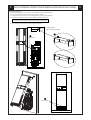
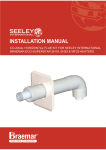
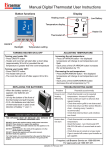
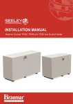
INSTALLATION MANUAL
CONSOLE KIT FOR SEELEY INTERNATIONAL
BRAEMAR ECO-SUPERSTAR SH18, SH25 & WF25 HEATERS
SH18/25
WF25
1
ATTACHING CONSOLE TO FRONT COVER
SH18/25
Attach console top panel to side panels
1. Use the supplied rivets (two on each side) to fix both
console side plates to the console top plate.
Ensure the side panels are fixed to the inside of the
top panel
Top panel
Side panel
Attach console panels to heater front cover
2. Using the supplied screws, attach the console
extension to the front cover as shown.
WF25
Attach console sides to heater front cover
1. Using the supplied screws, attach the console
extension to the front cover as shown.
1
2
SH18/25 COVER INSTALLATION
Fitting front cover
1. Connect earth lead from heater cover to body of heater.
2. Connect control loom (multi coloured ribbon cable) to main PCB on electrical mount panel - connection is labelled
"FRONT PANEL". The loom will fit in only the correct position.
3. Locate lower grille section on outlet spigot at bottom of heater - ensure that plastic spigot fits around sheetmetal
spigot at top and bottom and both sides. Guide the top grille section onto the top cover retaining bracket and
ensure that cover fits flush against the wall surface.
4. Fit 4 screws to secure front cover to body of heater.
Earth lead
1
PCB connection point is at
lower right corner for SH25
models, and lower left corner
for SH18 models.
Control loom
2
Push loom end-connector onto connector
marked "FRONT PANEL" on PCB.
Fit Screws
4
3
2
3
WF25 CONSOLE FRONT COVER INSTALLATION (NO FLUE COVER)
Fitting front covers
1. Move locating tab to front holes on pre installed top mounting bracket.
2. Connect earth lead from heater cover to body of heater
3. Locate slots in top of cover over locating tabs on top mounting bracket.
4. Locate lower grille section on outlet spigot at bottom of heater.
If cover is not flush against wall surface adjust locating tabs.
5. Fit 2 screws to secure front cover to body of heater.
Locating tabs
Top mounting bracket
1
2
Earth lead
3
5
Fit Screws
4
3
4
4
WF25 FLUE COVER INSTALLATION
Install ceiling trim frame
1. Install the ceiling trim frame between the cut-out (as per flue kit installation instructions) in the cornice with the
back edge against the wall and the top edge against the ceiling.
2. Fix in place by screwing from below into ceiling using toggle bolts or wood screws supplied.
3. Attach the flue cover bottom support bracket to the top of the front cover using 2 screws supplied in kit.
4. Fit the front cover to heater as described on page 3.
5. Cut the flue cover to length to suit the ceiling height. Calculate the length required as shown below
6. Slide cut end of flue cover into ceiling trim frame. Push bottom of flue cover in towards wall, spring lower sides out to
clear heater cover. Lower flue cover into lower support bracket on top of heater cover.
Flue cover bottom
support bracket
1
3
Ceiling trim frame
2
Cornice
Flue
DISTANCE 'X'
Ceiling
6
3
Front cover
5
FLUE COVER CUT LENGTH
= DISTANCE 'X' - 80 mm
Floor
2
1
Warranty Service
Australia 1-300-650-644
seeleyinternational.com
It is the policy of Seeley International to introduce continual
product improvement. Accordingly, specifications are subject to
change without notice. Please consult with your dealer to
confirm the specifications of the model selected.
636702b