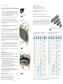
1
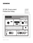
Scan QR Code
for more
information
SEM3™ – Embedded Micro Metering Module™
Quick Reference Guide
Installation considerations
Installation and maintenance of the SEM3 metering system
should only be performed by qualified, competent personnel
that have appropriate training and experience with high
voltage and current devices. The meter must be installed in
accordance with all local and national electrical codes.
The SEM3 system is made up of the following
components and options:
3.Meter racks – The meter modules are designed to snap into
the rack assemblies. The rack assemblies are sized by how
many modules will fit into each and come in 3, 9, 15 and 21
module configurations.
4.CT or current transformers – The SEM3 systems has solid
core CTs for use with the system in the following maximum
amperage ranges 50, 125, 250, 400, 600, 800 and 1200
amps. These are maximum amperage ranges for normal
usage but will measure accurately down to 1% of the
maximum range.
5.Communication cables – The communication cables
are designed like CAT 5 cables but are insulated for use
in systems up to 600 volts. The cables are for two way
communication from the controller to the rack/meter
modules.
1.Controller – The controller is used to communicate the
metered values to outside systems by way of a web page
interface, Modbus RTU or Modbus TCP. One controller can
manage up to 45 meter modules.1) The controller also has
the system digital inputs for receiving pulse inputs from
other metering devices as well as a digital output for the
combined KWh output of the system being metered.
2.Meter modules – There are two choices for the meter
modules that are differentiated by accuracy specification.
The accuracies are 1% for the standard accuracy modules
and 0.2% for the high accuracy modules. The accuracy is
tested in accordance to ANSI C12.20/0.2.
Figure 1 SEM3 System
Answers for infrastructure and cities.
Configuring the system
Ping statistics for 192.168.1.65:
Packets: Sent = 4, Received = 4, Lost = 0 (0% loss),
Approximate round trip times in milli-seconds:
Minimum = 56ms, Maximum = 78ms, Average = 65ms
There are a few steps in configuring the components of the SEM3 metering system.
Refer to the Installation Manual instructions on mounting of the SEM3 components.
Current Transformer (CT) – There is no setting on the CT for the system. The CTs for
use in the SEM3 meter system are 100 mA output and are self protecting so shorting
blocks are not required. Standard CT wire length is 6 feet. CT wire length can retain
accuracy up to 100 feet using 18 AWG twisted pair wire.
If not, then check your connection between the PC’s Ethernet port and
the Controller MODBUS TCP/IP port.
Solid core
Open Explorer or Chrome and type out the IP address 192.168.1.65.
Figure 2 Current transformer
At the Login Page, the default user name is “admin”, and the default password is “sem3”.
Meter modules – These instructions are for both levels of accuracy modules.
Each meter module is a single phase meter and must be connected to the
appropriately sized SEM3 system CT. The meter modules are then snapped into place
into a rack assembly. The rack assembly has the module address to the controller hard
coded in the hardware.
Note: For metering of multi-pole circuit breakers, the meter modules must be
mounted contiguously to each other.
Power and communication
indicator LED
LED indicates Phase position
switch location
Release lever to
allow easy removal
from the rack
Meter Racks – The meter module racks have the addresses for the module to
controller communications hard coded into them. The 9, 15 and 21 module racks
have a two position dip switch for setting one of two address ranges for each. The
three module rack has a rotary switch to allow it to be configured for multiple
address ranges. The chart below shows the ranges available for each rack.
Figure 5 Four meter rack options with meters snapped inside
Gaps in the rack will not allow multi-pole meters to be configured. Each module must
have the phase dip switch on the top of the module set to the phase that the CT is
metering; phase A, B, or C (Line 1, 2, or 3 respectively).
Note: Once the meter module is placed into the rack and energized the phase position
will be indicated by a different color LED for each position. These descriptions are for
the connections to the controller not the LED colors on the meter module. (L1 phase
A color is orange; L2 color is yellow; L3 color is green.) The LEDs are adjacent to the
phase numbers. The power indication LED also indicates communications by flashing.
CT sizing for each meter module will be done through the controller web page later in
configuration.
Controller – The controller functions as the set up interface for the system.
System settings, CT ratios, PT ratios, alarm settings, communications settings
and passwords are all set using the web page interface of the controller. See
Installation Manual instructions for mounting and dimensional information.
Blue mark indicates high
accuracy, and burgundy
mark indicates standard
accuracy
CT wire
terminal blocks
CT wire
screw terminals
Left (1)
Three phase wiring
QR
code Isolated
RS485C
Ping your SEM3 Controller (Default IP address: 192.168.1.65)
Open a Command Prompt and at the prompt type “ping” followed by a space & the
IP Address of your SEM3 and press Enter.
You should get the following:
Pinging 192.168.1.65 with 32 bytes of data:
9, 15 and 21
Position
Rack Dip
Switch
Setting
Figure 3 Meter module
To start – Connect the controller to a PC using the Ethernet / Modbus TCP port.
See Figure 4.
Assign Static IP address
To change the PC / computer’s IP address in Windows 7 / 8,
1.Type network and sharing into the Search box in the Start Menu and select
Network and Sharing Center when it comes up.
2.Then when the Network and Sharing Center opens, click on Change adapter
settings.
3.Right-click on your local adapter and select Properties.
4.In the Local Area Connection Properties window highlight Internet Protocol
Version 4 (TCP/IPv4) then click the Properties button.
5.Select the radio button and enter the correct IP address Ex. 192.168.1.100,
and Subnet mask 255.255.0.0. The PC static IP address should be in the
same IP address range of the SEM3 controller.
6.Close out of the Local Area Connections Properties window.
7.You can open the command prompt and do an ipconfig to see the network
adapter settings have been successfully changed.
Left chart indicates rack addresses for left setting on 9, 15 and
21 module racks and setting 0-7 on 3 module rack.
Left rail
MODBUS TCP/IP
Two energy
pulse in
Right rail
Energy pulse out
Single
Phase
Monitor
Modbus
Addresses
1
1
1
2
2
2
3
3
3
3
4
4
4
4
5
5
5
5
6
6
6
6
7
7
7
7
8
8
8
8
9
9
9
9
10
10
10
11
11
11
12
12
12
13
13
13
14
14
14
15
15
15
16
16
17
17
18
18
19
19
20
20
21
21
23
25
26
27
(continued on next page)
Open
Address
Space
21
Position
Rack
Modbus
Addresses
15
Position
Rack
Modbus
Addresses
9
Position
Rack
Modbus
Addresses
1
33
33
33
33
0
2
34
34
34
34
3
1
35
35
36
36
37
37
37
37
38
38
38
38
39
39
39
39
40
40
40
40
41
9
41
41
41
10
42
42
42
43
43
43
44
44
44
Right (2)
13
45
45
45
14
46
46
46
15
47
47
47
48
48
17
49
49
18
50
50
19
5
35
36
5
11
3
35
36
6
7
Open
Address
space
24
Single
Phase
Monitor
Modbus
Addresses
3
Position
Rack
Modbus
Addresses
2
Open
Address
Space
9, 15 and 21
Position
Rack Dip
Switch
Setting
3
Position
Rack Rotary
Switch
Setting
4
22
51
51
52
52
53
21
53
22
54
23
55
6
25
57
26
58
27
59
3
Position
Rack Rotary
Switch
Setting
3
Position
Rack
Modbus
Addresses
8
34
33
35
37
9
38
39
41
A
42
43
45
B
46
47
49
C
50
51
Open
Address
Space
53
D
Open
Address
space
56
54
55
57
Open
Address
Space
E
58
59
60
29
31
2
9
Position
Rack
Modbus
Addresses
1
30
Reply from 192.168.1.65: bytes=32 time=56ms TTL=250
Reply from 192.168.1.65: bytes=32 time=60ms TTL=250
Reply from 192.168.1.65: bytes=32 time=69ms TTL=250
Reply from 192.168.1.65: bytes=32 time=78ms TTL=250
15
Position
Rack
Modbus
Addresses
2
28
Figure 4 Controller
21
Position
Rack
Modbus
Addresses
Right chart indicates addresses for right setting on 9, 15, and
21 module racks and 8-F on 3 module rack.
7
29
61
30
62
31
63
61
F
62
63
32
The 3 module rack can be used as an extension to any of the other racks or pairs of racks. Settings must be such that no address is
used more than once. Duplication of addresses will return an error on setup.
3
Login page – Default user name is “admin”, Default password is
“sem3”. User name and password can be set to user preference and
are case sensitive. See the User Manual for more detail.
The web page has other settings available and can be accessed by
clicking on the tabs at the top of the page.
System settings – The following may be set from this page: (See user
manual for more information)
• IP configuration – For configuration of the IP address if using
Modbus TCP. Be sure to write down the new IP address as you will
lose communications once saved.
• RTU slave configuration – For setting of address if used as a Modbus
RTU device
• Real time refresh interval – Time interval for the web page to refresh
real time date
• Device description – For naming of the system
• Panel configurations to include:
• Demand sub interval – Number of measurements taken
in the sub interval
• Sub interval length – Time between intervals
• Voltage mode – Delta or Wye
• Line to Neutral / Line to Line voltage depending on
voltage mode
• Potential Transformer (PT) Primary voltage – Secondary
preset to 120
Save – Data changes must be saved before leaving this page or it will
be lost.
Reset
Data available from this page –
• Firmware version
• Serial number of the controller
Global settings – Global settings will be applied across all the meters
in the system. Each meter can be customized in the Branch meter
configuration screen. The alarms are for the meters and not meter
modules. Individual phase alarms can only be set for single pole
meters. Alarm delays are time settings where the meter is in alarm
condition before the alarm flag is set. This is to prevent momentary
conditions sending alarm flags.
Siemens Industry, Inc.
5400 Triangle Parkway
Norcross, GA 30092
1-800-241-4453
[email protected]
Order No. RPFL-SEM3Q-0514 | Ref. No. 814388 Rev. 1P
Printed in USA | © 2014, Siemens Industry, Inc.
www.usa.siemens.com/SEM3
Multi-pole circuit breaker configuration – This page is used to configure
the meter modules into meters. The bottom of the page displays those
meters configured from the bottom of the page. The meter configuration
is drag and drop from the available module column to the different meter
configurations (1, 2 or 3 pole). Note that modules have to be mounted
contiguously in the racks to be configured as multi-pole meters.
Branch meter configuration – This page allows for customization
of the configured meters. Custom alarms may be set that override
the global alarms as well as naming of the individual meters.
Real time data – This screen gives an overview of the alarm
status of the configured meters and allows for clearing of the
individual meter alarms. Clicking on the individual meters will
display that meters real time information to the right of the grid.
User profile – This page is accessible to all users who can modify
their details except the ‘User ID’ and ‘Access Level’. User ID and
Access Level are set by the Supervisor only from the User
management screen.
User management – This page is accessible to ‘Supervisor’ user
who can manage users’ accounts that includes adding, removing
and modifying the users. There are three levels of users available:
• Supervisor – Has the ability to see all data and modify setting
and clear alarms and add or modify user settings.
• Controller – Has the ability to see all data and to clear alarms.
Controller cannot see or modify user management.
• Observer – Has the ability to see data but is not allowed to
modify or clear alarms.
Diagnostics – This page is accessible to ‘Supervisor’ user.
The SEM3 metering system can work with supervisory systems
such as WinPM.Net, Power manager and other SCADA or Building
management systems that use Modbus protocol. The Modbus
registers for this product are such that configuration using the
controller web interface is not absolutely necessary, but by doing
so valuable time can be saved.
1) Some applications will allow for more than 45 poles in one enclosure by adding a
second controller. Two controllers can monitor up to 90 poles.
The information provided in this brochure contains merely
general descriptions or characteristics of performance which
in case of actual use do not always apply as described or which
may change as a result of further development of the products.
An obligation to provide the respective characteristics shall only
exist if expressly agreed in the terms of contract.
All product designations may be trademarks or product names
of Siemens AG or supplier companies whose use by third parties
for their own purposes could violate the rights of the owners.