1
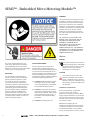
Scan QR Code
for more
information
SEM3™ - Embedded Micro Metering Module™
Installation Manual
Answers for infrastructure and cities.
SEM3™ - Embedded Micro Metering Module™
SUMMARY
These instructions do not purport to cover
all details or variations in equipment, nor
to provide for every possible contingency
to be met in connection with installation,
operation, or maintenance. Should further
information be desired or should particular
problems arise which are not covered
sufficiently for the purchaser’s purposes,
the matter should be referred to the local
the sales office.
THE CONTENTS OF THIS INSTRUCTION
MANUAL SHALL NOT BECOME PART OF
OR MODIFY ANY PRIOR OR EXISTING
AGREEMENT, COMMITMENT OR
RELATIONSHIP. THE SALES CONTRACT
CONTAINS ALL OBLIGATIONS OF
SIEMENS INDUSTRY, INC. THE WARRANTY
CONTAINED IN THE CONTRACT BETWEEN
THE PARTIES IS THE SOLE WARRANTY OF
SIEMENS INDUSTRY, INC.
Notices
DANGER
The use of unauthorized parts in the
repair of the equipment or tampering
by unqualified personnel will result in
dangerous conditions that can cause death,
serious injury or property damage.
IMPORTANT
The information contained herein is
general in nature and not intended for
specific application purposes. It does
not relieve the user of responsibility
to use sound practices in application,
installation, operation, and maintenance
of the equipment purchased. Siemens
reserves the right to make changes at
any time without notice or obligations.
Should a conflict arise between the
general information contained in this
publication and the contents of drawings
or supplementary material or both, the
latter shall take precedence.
QUALIFIED PERSONNEL
For the purposes of this manual and
product labels, “qualified personnel” is
one who has skills and knowledge related
to the construction and operation of the
electrical equipment and installations and
has received safety training to recognize
and avoid the hazards involved. In addition,
s/he has the following qualifications:
(a) is trained and authorized to energize,
de-energize, clear, ground, and tag
circuits and equipment in accordance
with established safety practices.
(b) is trained in the proper care and use
of protective gear equipment such as
rubber gloves, hard hat, safety glasses
or face shields, flash clothing, etc., in
accordance with established safety
procedures
(c) is trained in rendering first aid.
This symbol indicates the presence of
dangerous voltage within and outside
the product enclosure that will cause
death or serious injury if proper
precautions are not followed.
CAUTION
This symbol alerts the user to the
presence of hazards that may cause
minor or moderate injury to persons,
damage to property or damage to the
device itself, if proper precautions are
not followed.
Installation considerations
Environmental ratings: Temperature
to 14°F to 149°F (-10°C to 65°C).
Measurement Category III (CAT III), Mains
Supply Voltage Fluctuations up to 10% less
than nominal low range the mains supply
and 10% more than nominal high range of
mains power supply.
Measurement category III is for
measurements performed in the building
installation. Examples are measurements
on distribution boards, circuit-breakers,
wiring, including cables, bus-bars, junction
ii
SEM3™ - Embedded Micro Metering Module™ Installation Guide
boxes, switches, socket-outlets in the
fixed installation, and equipment for
industrial use and some other equipment,
for example, stationary motors with
permanent connection to the fixed
installation.
Installation and maintenance of the SEM3
metering system should only be performed
by qualified, competent personnel that
have appropriate training and experience
with high voltage and current devices. The
meter must be installed in accordance with
all local and national electrical codes.
DANGER
Failure to observe the following instructions will cause death or serious injury.
• During normal operation of the SEM3
meter, hazardous voltages are present
on its voltage leads, and throughout
the connected potential transformer
(PT), digital (status) input, control
power and external I/O circuits. PT
circuits are capable of generating lethal
voltages and currents with their primary
circuit energized. Follow standard
safety precautions while performing
any installation or service work (i.e.
removing PT fuses).
• The voltage leads to the meter should
not be user‐accessible after installation.
• Do not use digital output devices for
primary protection functions. These
include applications where the devices
perform energy limiting functions or
provide protection of people from injury.
Do not use the SEM3 in situations where
failure of the devices can cause injury or
death, or cause sufficient energy to be
released that can start a fire. The meter
can be used for energy management
functions.
• Do not HIPOT/Dielectric test the digital
(status) inputs, digital outputs, or
communications terminals. Refer to
the label on the SEM3 meter for the
maximum voltage level the device can
withstand.
• The SEM3 metering system offers a
range of hardware options that affect
input ratings. Use only parts and
assemblies that are made specifically
for use with the SEM3 system. Failure
to do so could permanently damage
the meter. This document provides
installation instructions applicable to
each hardware option.
FCC Notice
This equipment has been tested and found to comply with the limits for a Class A digital
device, pursuant to Part 15 of the FCC Rules. These limits are designed to provide
reasonable protection against harmful interference when the equipment is operated
in a commercial environment. This equipment generates, uses, and can radiate radio
frequency energy and, if not installed and used in accordance with the instruction
manual, may cause harmful interference to radio communications. Operation of this
equipment in a residential area is likely to cause harmful interference in which case the
user will be required to correct the interference at his own expense.
Standards Compliance
• Approvals and certifications
–
Accuracy
-ANSI C12.1
-ANSI C12.20/0.2
–
Safety/Construction
-CSA C22.2 No. 1010-1 Safety Requirements for Electrical Equipment for
Measurement
-UL916 Energy Management Equipment
-UL61010-1 (IEC 61010-1) Test and Measurement Equipment
–
Electromagnetic Compatibility
-IEC 61000-4-2 Electrostatic Discharge (B)
-IEC 61000-4-3 Radiated Immunity (A)
-IEC 61000-4-4 Electric Fast Transient (B)
-IEC 61000-4-5 Surge Immunity (B)
-IEC 61000-4-6 Conducted Immunity
-FCC Part 15 subpart B, Class A Digital Device, Radiated Emissions
–
Environmental Conditions
-Altitude up to 3000 meters
-Maximum relative humidity 80% for temperatures up to 31°C decreasing
linearly to 50% relative humidity at 40°C
-Pollution Degree 3
Made by Siemens Industry, Inc.
SEM3™ - Embedded Micro Metering Module™ Installation Guide
iii
SEM3™ - Embedded Micro Metering Module™
Table of Contents
Chapter 1
Chapter 2
Chapter 3
Introduction
2
Overview
2
Receiving, handling and storage
3
Receiving
3
SEM3 Components
3
Storage
3
Installation
4
Installation
5
SEM3 Controller
6
- Catalog number – US2:SEM3CONTROLLER
6
- Mounting
6
- Voltage Inputs
7
- Voltage Leads
7
Rack Assemblies
8
- Catalog numbers
8
Meter Modules
9
- Catalog numbers
9
- Step-by-step instructions
9
Current Tranformers
11
- Solid Core Catalog Numbers
11
- CT ratings for Solid Core CTs for use with the
SEM3 metering system
11
Communication Cables
12
- Cable catalog numbers
12
These instructions do not purport to include all details or variations in equipment, nor to provide for every possible contingency that may occur
in connection with installation, operation or maintenance. Should further information be desired or should particular problems which are not
covered sufficiently for the purchaser’s purposes, the matter should referred to the local Siemens sales office. The contents of this instruction
manual shall not become part of or modify any prior or existing agreement, commitment or relationship. The sales contract contains the entire
obligation of Siemens. The warranty contained in the contract between the parties is the sole warranty of Siemens. Any statements contained
herein do not create new warranties or modify the existing warranty.
SEM3™ - Embedded Micro Metering Module™ Installation Guide
1
Chapter 1 – Introduction
Overview
The SEM3 system is designed to measure
the current, voltage, and energy
consumption of up to 45 circuits.1)
The SEM3 consists of a controller, racks,
cables, meter modules and current
transformers (CTs) that can be tailored to
the application. The CTs are available in
solid core versions and are to be mounted
along the termination points of each
breaker pole being metered. The conductor
passes through the appropriate current
sensor before terminating at the breaker.
Each CT is terminated into a meter module
that in turn is mounted in a rack. The racks
get power from and communicate back to
the controller through special cables that
are part of the SEM3 product line.
The SEM3 has the ability to communicate
Modbus RTU via RS485 or Modbus TCP via
and Ethernet port to outside systems. Real
time values may also be viewed from the
controller web pages.
The controller web pages are also used
to configure the SEM3 system to the
application. Systems info, CT ratio setting
and alarms as well as configuring the
meter modules into 1, 2 or 3 pole meters
are all accomplished through embedded
and easy to use web pages. See the SEM3
User Manual for more application specific
information at www.usa.siemens.com/
SEM3.
Figure 1 SEM3 Overview Diagram
1) Some applications will allow for more than 45 poles in one enclosure by adding a second controller. Two controllers can monitor up to 90 poles.
2
SEM3™ - Embedded Micro Metering Module™ Installation Guide
Chapter 2 – Receiving, handling and storage
Receiving
SEM3 components
Storage
The SEM3 may be shipped as individual
units. Refer to the shipping slip/bill of
lading to identify all items included in the
shipment.
• Current transformers – solid core CTs in
the following maximum ranges 50, 125,
250, 400, 600, 800 and 1200 amps.
• Meter modules –1% standard accuracy
modules and 0.2% high accuracy
modules2)
• Racks – 3, 9, 15 and 21 module
configurations.
• Controller
• Communication cables
• CT supports – specific to the type of
breaker and the CTs they are holding.
If the SEM3 components are not installed
and energized immediately, they should be
stored in a clean dry area where a uniform
temperature prevents condensation.
Preferably, it should be stored in a heated
building, with adequate air circulation and
protected from dirt and water. It should be
stored where it is not subject to mechanical
damage.
1. When your shipment arrives, note
whether the equipment is properly
protected.
2. Make an immediate inspection for
visible damage upon arrival and prior to
disturbing or removing from packaging.
Note visible damage on the delivery
receipt. Take pictures when possible.
3. Notify the Siemens sales office
immediately of any damage.
All of the above components may be
shipped fully assembled in gear. If there are
any shortages or damages not previously
noted, make certain they are noted on the
delivery receipt and contact the carrier
immediately. Also, notify the Siemens Sales
Office.
If the components are to be stored for any
length of time prior to installation, restore
the packing for protection during that
period. Where conditions permit, leave the
packing intact until the components are at
their final installation location.
2) 0.2% high accuracy is only possible with Siemens SEM3 Solid Core CTs.
SEM3™ - Embedded Micro Metering Module™ Installation Guide
3
Chapter 3 – Installation
Figure 2 below illustrates Embedded
Micro Metering Module components in a
panelboard. This is only an example, other
applications can apply.
Fusible Disconnect Switch 3)
CT cables
Controller
Meter module
600V isolated cable
Meter rack
Figure 2 SEM3™ - Embedded Micro Metering Module™ components in a panelboard
3) The switch or circuit breaker must be marked as the disconnecting device for the meter.
It is recommended that the meter be mounted near the disconnecting device in an area with adequate ventilation.
The disconnect should not be positioned in a manner that makes it difficult to operate the disconnecting device.
4
SEM3™ - Embedded Micro Metering Module™ Installation Guide
Installation (continued)
Installation
An SEM3 system must consist of at least
(1) controller, (1) meter module,
(1) current transformer, (1) rack assembly
and (1) communication cable. The system
can be scaled up using the components up
to 45 meter points.4)
For complete detail on SEM3 system and
configuration, refer to the SEM3 User
Manual.
Note: Field-installed Class 2, Class 3, and
other low voltage conductors shall be
separated by a minimum 1/4 inch (6.4mm)
from factory- or field-installed electric
light, power, Class 1, non-power-limited
fire alarm circuit conductors, and medium
power network-powered broadband
communications cables. Separation of
conductors may be obtained by clamping,
routing, or an equivalent means.
Note: For field installations, the meter shall
be mounted inside a UL Listed enclosure.
The minimum enclosure size should be no
smaller than 18” x 12” x 4”.
This is a minimum enclosure size. To
include the fusible disconnect and other
components, a larger enclosure may be
required.
4) Some applications will allow for 63 poles in one enclosure by adding a second controller. Two controllers can monitor up to 90 poles.
SEM3™ - Embedded Micro Metering Module™ Installation Guide
5
Installation (continued)
SEM3 Controller
Catalog number –
US2:SEM3CONTROLLER
The SEM3 controller is the heart of the
SEM3 system. The controller is to be
connected to the voltage source and to the
racks and meter modules. All configuration
of the system is done via the controller
embedded web pages. Refer to the
User Manual available at www.siemens.
com/sem3 for more information on
configurations.
Mounting
The controller should be securely mounted
and protected against damage from power
cables. All applicable codes and standards
must be observed. The controller has
mounting holes at each end that can be
used for mounting to a back plane. The
controller may be mounted remote to the
gear in a separate enclosure.
See Figure 3 for dimensional information.
Figure 3 Controller dimensions
6
SEM3™ - Embedded Micro Metering Module™ Installation Guide
Installation (continued)
Ratings
Power Supply: 120-480 Vac
Frequency: 60 Hz
Systems: Single or three phase systems
(Wye or Delta)
Power consumption: 110 mA
Fuse protection: Type CC, 3 A, Time- Delay
but less than or equal to 600 Vac systems
will require PT between the Controller and
the supply voltage. See the user manual
for more information on setting the meter
system for use on 600 Vac systems.
Voltage inputs
The controller has five leads that are color
coded and labeled to the appropriate
phases and ground connection. All phase
(ungrounded ) connections should be
protected by a 3 amp fuse or circuit breaker
that is appropriate for the applied voltage
and available short circuit rating. (Example:
a type CC fuse rated at 3 amp (Time-Delay)
and good for application on up to a 200
kAIC system at 480 volts).
For three phase four wire systems –
phase A (line 1) is black in color, phase B
(line 2) is red in color, phase C (line 3) is
blue in color, neutral is white in color and
equipment ground is green (with a yellow
stripe) in color.
The SEM3 metering system may be direct
connected to any AC system that has a line
to line voltage less than or equal to 480
Vac and Line to neutral or ground voltage
less than 277 volts. Greater than 480 Vac,
The Voltage leads are as follows
Where applicable, “connect 14 AWG
min., 600 V min. insulated wiring for Line
voltages and Neutral to the appropriate
locations in the breaker panel, in
accordance with all national and local
electrical codes”.
For three phase three wire systems –
phase A (line 1) is black in color, phase B
(line 2) is red in color, phase C (line 3) is
blue in color, neutral is white in color is
to be removed or tied out of the way and
equipment ground is green (with a yellow
stripe) in color.
For single phase three wire systems –
phase A (line 1) is black in color, phase B
(line 2) is red in color, phase C (line 3) is
blue in color is to be discarded or tied out
of the way, neutral is white in color and
equipment ground is green (with a yellow
stripe) in color.
See the user manual for information on
setting the system parameters.
Note: Wiring from the controller to the
racks, wiring to and from the digital inputs
and output are considered Class 2 wiring.
Care should be taken to keep these wires
and cable separated from power cables per
standard requirements. 5)
Note: Connector torque rating for wiring
terminals is 5 IN-LBS
Three phase wiring
Left rail
QR code
Right rail
Isolated
RS485C
Two energy
pulse in
MODBUS TCP/IP
Energy pulse out
Figure 4 Diagram of front of SEM3 controller
5) Refer to Field-Installation Note on Page 5.
SEM3™ - Embedded Micro Metering Module™ Installation Guide
7
Installation (continued)
Rack Assemblies
Catalog numbers
3 position rack – US2:SEM3RACK3
9 Position rack – US2:SEM3RACK9
15 Position rack – US2:SEM3RACK15
21 Position rack – US2:SEM3RACK21
The communication cables come in varying
lengths from 6”, 12”, 24”, and 36”. The
communication cables are considered Class
2 wiring so routing of these cables also
needs to be considered in the location of
the rack assembly.6)
The meter module rack assemblies should
be securely mounted to a back plane in
an area as to be protected from damage.
The meter modules snap into the rack
assemblies for mounting. Make sure you
have allowed clearance for the meter
modules in your selection of mounting
areas. The racks are connected to the
controller using communication cables.
The rack assemblies have the meter
module addressing hard wired into their
construction. Dip switches and or rotary
switches are provided on the rack to allow
each to have unique addressing available
for the meter modules. See the user
manual for more information on the rack
addressing.
Each rack has mounting holes on opposing
corners for mounting. See the dimensional
drawings below for details.
Figure 5 Four meter rack options with meters
snapped inside
21 Pos
2.41
15 Pos
2.41
9 Pos
2.41
14.15
10.61
3 Pos
2.41
7.07
3.57
1.83
Catalog no.
US2:SEM3RACK3
1.83
Catalog no.
US2:SEM3RACK9
1.83
1.83
Catalog no.
US2:SEM3RACK15
Catalog no.
US2:SEM3RACK21
Figure 6 Rack dimensions
6) Refer to Field-Installation Note on Page 5.
8
SEM3™ - Embedded Micro Metering Module™ Installation Guide
Installation (continued)
Meter Modules
Catalog numbers
High accuracy – US2:SEM3HAMETER
Standard accuracy – US2:SEM3LAMETER
Step by step instructions are as follows:
Installing both accuracy levels of SEM3
meter modules into the SEM3 meter rack
The meter modules are designed to snap
into place in the rack assemblies. There
are guides on the module and in the rack
assemblies to help insure proper placement
of the modules in the rack. If the module
is forced into the rack assembly improperly
it can damage the meter module and rack.
The module should easily fit into the rack
assembly and have audible clicking when
locked into position. To remove the meter
module the release tabs should be pressed
together and lift the module straight out of
the rack. Refer to the user manual for more
information on this setting. See the rack
assembly dimensional drawing for sizing of
the meter module plus rack assembly.
1. Connect the appropriately sized SEM3
system CT in the CT wiring terminal.
Insure that the CTs leads are firmly
secured to the meter module.
Note: Once the meter module is placed
into the rack and energized the phase
position will be indicated by a different
color LED for each position. Colors are
orange for phase A (line 1), yellow for
phase B (line 2), green for phase C
(line 3). LED are adjacent to the phase
numbers. The power indication LED also
indicates communications by flashing.
2. Snap or place the SEM3 module into an
open slot in the meter rack assembly.
3. Note that modules must be mounted
contiguously in the racks to be
configured for multi-pole circuit
breakers. Gaps in the rack will not allow
multi-pole meters to be configured as
multi-pole meters.
4. Set the phase dip switch on the top of
the module to the phase that the CT is
metering, phase A, B, or C (line 1, 2, or 3
respectfully).
Power and communication indicator LED
added to the top of the meter unit
LED added to indicate Phase
postion switch location
The blue mark indicates high accuracy, and the
burgundy mark indicates standard accuracy
Release lever to allow easy
removal from the rack. No
tools required.
CT wire terminals blocks. CTs will be
shipped disconnected to allow custom
lead length and change meter amperage.
There will be two meter modules based
on accuracy and not on ampacity.
Figure 7 SEM3 Meter Module
CT wire screw terminals
SEM3™ - Embedded Micro Metering Module™ Installation Guide
9
Installation (continued)
Figure 8 SEM3 meter front view
Figure 9 SEM3 meter isometric view
Figure 10 Meter module dimensions
10
SEM3™ - Embedded Micro Metering Module™ Installation Guide
Installation (continued)
Current Transformers
The CTs used with the SEM3 metering
system are specifically designed and rated
for use with the system. Use of other CTs
can be damaging to SEM3 components
and cause hazardous situations. All the CTs
used with this system are in compliance
with the most up to date safety standards.
Use only UL Listed Energy Monitor Current
Transformers, evaluated and approved for
SEM3 application. All CTs should be secured
within the gear to protect against damage.
Size CT primary rating with the load to be
measured. The CT primary rating should be
equal to or greater than the load.
Solid core catalog numbers
50:0.1 Solid Core CT - US2:SEM3SCCT50
125:0.1 Solid Core CT - US2:SEM3SCCT125
250:0.1 Solid Core CT - US2:SEM3SCCT250
400:0.1 Solid Core CT - US2:SEM3SCCT400
600:0.1 Solid Core CT - US2:SEM3SCCT600
800:0.1 Solid Core CT - US2:SEM3SCCT800
1200:0.1 Solid Core CT - US2:SEM3SCCT1200
Note: For Solid Core CTs, Wire conductors
RHH, RHW, and RHW-2 will not be used.
(Conductor outer diameter larger than CT
inner diameter). Reference NEC 2014 Edition,
Table 5, Page 70-761.
250 KCMIL Max Conductor for 250A CT.
CT ratings for Solid Core CTs for use with
the SEM3 metering system
• 100mA output
• Lead wires are 18AWG, Stranded 16/30
– Primary Rating: 600VAC
– Overvoltage Category: CATIII
– BIL: 10kV, Fullwave
– Amplitude error: ± 0.2%
– Phase error: <0.2 (<12 Min)
– Overload rating: 6 x Ip for 30 seconds
As a reminder, the CTs used with the SEM3
metering system are specifically designed
and rated for use with the system. All
the CTs used with this system are in
compliance with the most up to date safety
standards. Use only Siemens SEM3 CTs with
the SEM3 system. All CTs should be secured
within the gear to protect against damage.
Size CT primary rating with the load to be
measured. The CT primary rating should be
equal to or greater than the load. CTs
should be secured using standard practices
and follow all codes and standards and
are subject to local authorities having
jurisdiction.
Figure 11 Typical Solid Core CT
Note: CATIII current transformers are not
suitable for use with service entrance
conductors. The use of these CTs shall
be limited to non-service conductor
locations.
Note:
•
•
•
CTs should be securely fastened such
that they will not slide down to live
terminals.
WARNING - to reduce risk of electric
shock, always open or disconnect the
circuit from the power distribution
system of a building before installing or
servicing current transformers.
In accordance with NEC, CTs may not
be installed in any panel board where
they exceed 75% of the wiring space of
any cross sectional area.
SEM3™ - Embedded Micro Metering Module™ Installation Guide
11
Installation (continued)
Communication cables
The communications cables connect the
meter racks to the controller and connect
meter racks together in series. Multiple
lengths are available to suit a wide variety
of configurations. Although the cables may
look like standard Ethernet cables they are
600V insulated wires but are considered
Class 2 wiring. Care should be taken to
follow codes and standards for clearance
and isolation7) of Class 2 wiring from
power wiring. Use only SEM3 components
with the system. Failure to use SEM3
components from Siemens could cause
damage to the product and place the user
at risk of or electrical shock or fire.
Cable catalog numbers
6” cable - Controller to rack US2:SEM3CAB6INCH
12” cable - Controller to rack US2:SEM3CAB12INCH
24” cable - Controller to rack US2:SEM3CAB24INCH
36” cable - Controller to rack US2:SEM3CAB36INCH
6”
12”
24”
36”
7) Refer to Field-Installation Note on Page 5.
12
SEM3™ - Embedded Micro Metering Module™ Installation Guide
Notes
SEM3™ - Embedded Micro Metering Module™ Installation Guide
13
Notes
14
SEM3™ - Embedded Micro Metering Module™ Installation Guide
Notes
SEM3™ - Embedded Micro Metering Module™ Installation Guide
15
Siemens Industry, Inc.
5400 Triangle Parkway
Norcross, GA 30092
Order No. PDIM-SEM3N-0514
Printed in USA
Subject to change without prior notice
© 2014 Siemens Industry, Inc.
1-800-241-4453
[email protected]
www.usa.siemens.com/SEM3
The information provided in this brochure contains merely
general descriptions or characteristics of performance
which in case of actual use do not always apply as
described or which may change as a result of further
development of the products. An obligation to provide
the respective characteristics shall only exist if expressly
agreed in the terms of contract.
All product designations may be trademarks or product
names of Siemens AG or supplier companies whose use by
third parties for their own purposes could violate the rights
of the owners.