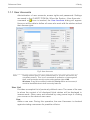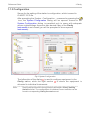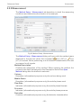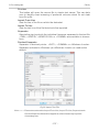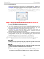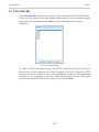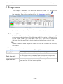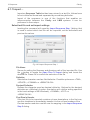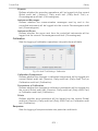
1
Clarity
Reference Guide
Clarity
ENG
Code/Rev.: M018/50A
Date: 9. 9. 2013
Phone: +420 251 013 400
Fax: +420 251 013 401
[email protected]
www.dataapex.com
DataApex Ltd.
Petrzilkova 2583/13
158 00 Prague 5
The Czech Republic
Sections of the manual connected only to the Clarity Full version are marked with the
icon.
Clarity ® , DataApex ® and ® are trademarks of DataApex Ltd. Microsoft ® and Windows TM are
trademarks of Microsoft Corporation.
DataApex reserves the right to make changes to manuals without prior notice. Updated manuals can be
downloaded from www.dataapex.com.
Author: DM
Reference Guide
Table of Contents
Contents
1 Clarity
1.1 System
1.1.1 User Accounts
1.1.2 User Details
1.1.3 Configuration
1.1.3.1 Left section of the System Configuration dialog
1.1.3.2 Available Control Modules
1.1.3.3 A/D Converter Setup
1.1.3.4 Right section of System Configuration dialog
1.1.4 Directories
1.1.5 GLP Options…
1.1.6 Digital Outputs
1.1.6.1 Select Control
1.2 Login
1.3 Logout
1.4 Lock
1.5 View
1.5.1 Customize…
1.6 Help
1.6.1 Register
1.6.1.1 Register Clarity question
1.6.2 Check for Updates
1.6.3 User Code…
1.6.3.1 Language Selection
1.6.4 Send Report by E-Mail
1.6.5 About…
2 Instrument
2.1 Clarity Lite window specifics
2.2 File
2.2.1 Open Method
2.2.1.1 Open Method (Sequence, Chromatogram, Calibration)
2.2.2 Send Method by Email
2.2.3 Project
2.2.3.1 Error Opening Project
2.2.4 Archive
2.2.5 Restore
2.3 Monitor
2.3.1 Device Monitor
2.3.1.1 File
2.3.1.2 Control
2.3.1.3 View
2.3.1.4 Window
2.3.1.5 Help
2.4 Analysis
-i-
1
2
3
8
9
10
12
15
16
21
23
25
26
27
28
29
30
31
32
32
34
35
36
37
38
39
40
41
42
44
45
47
48
49
50
52
54
55
56
56
57
57
57
58
Table of Contents
Clarity
2.4.1 Single
2.4.1.1 Chromatogram File Name
2.4.1.2 Rich Text Edit
2.4.2 Sequence
2.4.3 Batch
2.5 Method
2.5.1 Event Table
2.5.1.1 Events used in Active Sequence
2.5.2 Measurement
2.5.3 Acquisiton
2.5.4 Integration
2.5.4.1 Integration table items
2.5.5 Calculation
2.5.6 Advanced
2.5.7 GC (LC) Control, LC Gradient
2.5.8 AS
2.6 Setting
2.6.1 Export Data
2.6.2 Postrun…
2.7 View
2.7.1 Options…
2.7.1.1 General tab
2.7.1.2 Graph tab
2.7.1.3 Axes Appearance tab
2.7.1.4 Signals & Curves tab
2.7.1.5 Auxiliary Signals tab
2.7.1.6 Gradient tab
2.7.1.7 Directories tab
2.8 Window
2.9 Help
3 Chromatogram
3.1 File
3.1.1 Overlay Mode
3.1.2 Open Chromatogram
3.1.3 Open Chromatogram Sequentially
3.1.4 Open Chromatogram from Sequence
3.1.5 Save As…
3.1.6 Import Chromatogram…
3.1.6.1 AIA
3.1.6.2 Text and EZChrom ASCII
3.1.6.3 Import RAW…
3.1.7 Export Chromatogram
3.1.8 Sign
3.1.9 Verify
3.1.10 PostRun Setting (From Chromatogram Window)
3.2 Edit
3.2.1 Add User Column
- ii -
59
64
66
66
67
71
73
79
80
82
84
85
88
92
95
95
96
96
100
103
103
104
107
110
111
112
113
115
116
117
118
122
126
127
129
131
132
133
134
136
139
140
142
144
145
148
151
Reference Guide
Table of Contents
3.2.2 Setup Columns…
3.3 Display
3.3.1 Preview Graph
3.3.2 Properties
3.3.2.1 Graph Properties - Graph tab
3.3.2.2 Graph Properties - Axes Appearance tab
3.3.2.3 Graph Properties - Time Axis tab
3.3.2.4 Graph Properties - Signal Axis tab
3.3.2.5 Graph Properties - Signals tab
3.3.2.6 Graph Properties - Auxiliary Signals tab
3.3.2.7 Graph Properties - Gradient tab
3.4 Chromatogram
3.4.1 Baseline
3.4.1.1 Lock
3.4.1.2 Valley
3.4.1.3 Together
3.4.1.4 Forward Horizontal
3.4.1.5 Backward Horizontal
3.4.1.6 Front Tangent
3.4.1.7 Tail Tangent
3.4.1.8 Clamp Negative
3.4.1.9 Cut Negative
3.4.1.10 Reject Negative
3.4.1.11 Allow Crossing
3.4.1.12 Spike Removal
3.4.2 Peak
3.4.2.1 Start
3.4.2.2 End
3.4.2.3 Both
3.4.2.4 Add Positive
3.4.2.5 Add Negative
3.4.2.6 Force Peak Name
3.4.2.7 Solvent Peak
3.4.2.8 Groups
3.4.3 Integration
3.4.3.1 Local Peak Width
3.4.3.2 Local Threshold
3.4.3.3 Integration Interval
3.4.3.4 Detect Negative
3.4.3.5 Minimal Area
3.4.3.6 Minimal Height
3.4.3.7 Minimal Half Width
3.4.3.8 Detector Delay
3.4.3.9 FFT Filter
3.4.3.10 Savitzky-Golay Filter
3.4.3.11 Moving Average Filter
3.4.3.12 Spike Filter
- iii -
154
156
157
159
160
161
162
164
166
169
170
171
174
175
175
175
175
175
176
176
176
176
176
176
177
178
178
179
179
179
180
180
181
182
183
184
186
187
187
188
188
188
189
189
189
189
189
Table of Contents
Clarity
3.4.4 Separation
3.4.4.1 Valley To Valley Slope
3.4.4.2 Tangent Area Ratio
3.4.4.3 Tangent Slope Ratio
3.4.5 Noise & Drift
3.4.5.1 Noise Evaluation
3.4.5.2 ASTM Noise Evaluation
3.4.5.3 6-Sigma Noise Evaluation
3.4.5.4 Drift Evaluation
3.4.6 Overlay
3.4.6.1 Move
3.4.6.2 Scale
3.4.6.3 Original
3.4.6.4 3D View
3.4.6.5 Clear 3D
3.4.6.6 Properties…
3.4.6.7 Mathematics… (Mathematical Operations dialog)
3.4.7 Chromatograms
3.4.8 Create Label
3.4.9 Set Signal Names
3.5 Method
3.5.1 Calculation
3.5.2 Integration
3.5.3 Measurement
3.6 Results
3.6.1 Local Table Menu
3.6.2 Result Table
3.6.3 Summary Table
3.6.3.1 Summary Options
3.6.4 Performance Table
3.7 SST
3.8 View
3.9 Window
4 Calibration
4.1 Calculate By
4.2 File
4.2.1 Save As…
4.3 Edit
4.4 Display
4.4.1 Graph Properties
4.5 Calibration
4.5.1 Add All
4.5.2 Add Existing
4.5.3 Add Peak
4.5.3.1 Calibrate Peak
4.5.3.2 Recalibrate Peak
4.5.4 Add Group
- iv -
190
190
190
190
191
192
193
193
193
194
195
196
196
196
197
197
198
200
201
204
205
207
212
216
220
220
222
228
230
232
235
236
237
238
251
252
255
256
257
258
260
263
264
265
265
267
269
Reference Guide
Table of Contents
4.5.4.1 Calibrate Group
4.5.4.2 Recalibrate Group
4.5.5 Options
4.5.5.1 Options
4.6 View
4.7 Window
5 Data Acquisition
5.1 File
5.2 Analysis
5.3 Display
5.3.1 Properties…
5.4 View
5.4.1 Axes Ranges
5.5 Window
6 Sequence
6.1 File
6.1.1 Import…
6.2 Edit
6.2.1 Fill Series
6.3 Sequence
6.3.1 Sequence Options
6.4 View
6.5 Window
7 Audit Trail
7.1 Station Audit Trail
7.1.1 File
7.1.2 Open Audit Trail (Append)
7.1.3 Export
7.1.4 Edit
7.1.5 Filter
7.1.6 View
7.1.7 Properties…
7.1.8 Window
7.2 Local Audit Trails
7.2.1 File
7.2.2 Edit
7.2.3 View
7.2.4 Properties…
8 Report Setup
8.1 List of tabs:
8.2 Page Setup
8.3 Lab. Header
8.4 Report Header
8.5 Method
8.6 Calibration
8.7 Chromatogram
8.8 Results
269
269
270
275
277
278
279
281
282
285
286
289
291
293
294
301
303
306
308
309
313
317
317
318
319
319
320
321
322
323
323
324
326
327
328
328
329
330
333
335
336
338
340
342
344
346
348
-v-
Table of Contents
Clarity
8.9 Sequence
8.10 Audit & Signatures
8.11 Print Preview
8.12 Print
9 Troubleshooting
9.1 Report error after Clarity crashed
9.2 How to get help
9 Appendices
9.3 List of terms
9.4 Shortcuts
10 Technical Specification
10.1 Declaration of Software Validation
10.2 Command line parameters
10.2.1 List of commands
10.2.2 Examples
10.2.2.1 Example 1:
10.2.2.2 Example 2:
10.2.2.3 Example 3:
10.2.2.4 Notes:
10.3 clarity.ini file
Index
349
350
352
354
355
355
355
356
356
362
364
364
364
365
386
386
386
386
387
388
390
- vi -
Reference Guide
Table of Contents
To facilitate the orientation in the Reference Guide manual and Clarity chromatography station,
different fonts are used throughout the manual. Meanings of these fonts are:
Instrument (blue text) marks the name of the window, to which the text refers.
Open File (italics) describes the commands and names of fields in Clarity, parameters that can
be entered into them or a window or dialog name (when you already are in the topic describing
the window).
WORK1 (capitals) indicates the name of the file and/or directory.
ACTIVE (capital italics) marks the state of the station or its part.
The bold text is sometimes also used for important parts of the text and the name of the Clarity
station. Moreover, there are text sections written in format other than normal text. These sections are
formatted as follows:
Note:
Notifies the reader of possibly interesting information.
Caution:
Warns the user of possibly dangerous or very important
information.
▌ Marks the problem statement or trouble question.
Description: Presents any closer information on the problem, describes its causes etc.
Solution:
Marks the response to the question, presents a procedure how to remove it.
- vii -
Reference Guide
1 Clarity
1 Clarity
The main window of the Clarity station contains Instrument icons as well
as a menu for the configuration of the station, opening and closing
Instruments etc.
Fig 1: Main Clarity window
Clicking the Instrument icon or the Login button will open the Instrument
window.
In the screenshot there are two opened Instruments (My GC and My LC),
both used by the user Administrator. The other two instruments (My Offline
GC and My Offline LC) are closed.
Above the instrument is the Name of the Instrument and bellow the closed
instrument is the Login button and after opening it will display the Name of
the currently logged user.
While trying to open Clarity Instruments or some other dialogs (User
Accounts , System Configuration and others) or to invoke certain
commands, the Login Dialog appears. This dialog is described in detail in
the
Starting and closing Clarity
While the Clarity is starting or closing, the starting or closing splashscreen
is visible instead of the main Clarity window. This might be important
mainly with some of the control modules because of the quite long times
when Clarity loads or unloads the necessary drivers.
Fig 2: Clarity starting and closing splashscreens
-1-
1 Clarity
Clarity
Clarity Switch
It is possible to scale down the main window by double- clicking the
window title bar or by the command View - Switch.
To restore the original size, double-click the title bar once more.
Fig 3: Main window as Clarity Switch
1.1 System
Submenu with system commands:
User Accounts
Sets the access rights and passwords particularly for
the administration of user accounts.
User Details
Shows the details of user account settings even to
the users that don't have the access to the User
Accounts dialog.
Configuration
Sets the station HW configuration.
Directories
Sets directories for individual Instruments.
Clarity2Go
Sets the communication with server for watching
instruments in your iPhone or Android phone.
Digital Outputs
Sets the outputs control.
Audit Trail
Displays the records of selected station tasks and
sets their logging.
Exit
Exits the program. If the measurement is active on
any Instrument, you will be notified. You will also be
prompted to save changed files.
Invoking commands from the System menu or the Help - User Code…
command requires all instruments to be closed. The user has to Logout all
instruments. In case the Logout All Now button is disabled, an Instrument
is locked. Unlock the Instrument manually (for more details see the
chapter Lock on pg 29)..
Fig 4: Logout all instruments
-2-
Reference Guide
1 Clarity
1.1.1 User Accounts
Administration of user accounts, access rights and passwords. Settings
are saved in the CLARITY.PSW file. When the System - User Accounts…
command or
icon is invoked, the User Accounts dialog will appear.
Here you will be able to define all users who work with the station and set
their access rights.
Fig 5: User Accounts
Note:
Setting access rights is used predominantly to prevent intervention by
untrained persons. This is not conceived as protection of data against
theft - such protection would require setting access rights in MS
Windows. If any file is modified outside the Clarity station environment, it
would be identifiable due to built-in security features.
User List
Provides a complete list of previously defined users. The name of the user
to whom the content of all displayed fields relates will be displayed in
inverse mode. Other users are selected by using arrow keys or clicking
your mouse on the desired user name.
New
Adds a new user. During this operation, the new Username is checked
against existing usernames for possible collision.
-3-
1 Clarity
Clarity
Delete
Erases a selected user from the user list. When deleting all users the
station automatically switches to “all users” (no password) mode.
Password Restrictions
Caution:
Password Restrictions parameters are common to all users.
Min. Length
Refers to the minimum length of the password entered. A password
shorter than the prescribed number of characters will not be accepted.
Life Time
Refers to the period of a password's validity. After its expiration the user
must select a new password.
Expiration Warning
Alerts the user as to the number of days prior to a password’s expiration.
Password Reuse
Relates to the period from which an already used password can be used
again.
Auto Lock
If the user doesn't have any activity in Windows, all opened Instruments
will be locked after specified time in minutes. All windows opened on
instruments will be hidden and the user has to unlock the Instrument by
clicking on its picture in the Clarity window.
User Details for:
The fields displayed in the lower part of the window always relate to the
user whose username is selected from the User List. The selected name
will be displayed in inverse mode (i.e. white on a blue background). Only
a user with adequate access rights can change the settings of those
access rights (selected
Rights).
Open User Accounts under User Access
User
User Name
The User’s name will automatically be placed in all headers of files that
are created while working in the station. The username will be displayed
along with the Created by or Analyst phrase when a file is selected. It is
compulsory for a user to fill in this field and forbidden for two users to have
the same username.
Desktop File
Refers to the name of the file (*.DSK) in which the desktop settings are
saved. The file contains settings regarding size, location and visibility of
the Instrument windows as well as all the amendable Instrument
-4-
Reference Guide
1 Clarity
parameters which are not part of system files. If this field is left empty, it will
be filled in automatically according to the User Name field.
This setting is common to all Instruments the user has available.
Note:
If you wish to share the same settings for several users, you can link them
to the same desktop file.
Description
Provides a user’s detailed description.
Note:
User Name and Description are part of signature during electronic
signing.
Other Users Can
Read & Write
Other users can view and edit your files.
Read
Other users can view your files but cannot edit or otherwise modify them.
No Access
Other users does not have any access to your files (even for reading
them).
Access To
Instrument X
Defines which Instruments the user may access within a station.
User Access Rights
Open User Accounts
A user with access to user accounts can add, delete or change the access
rights of other users. A selected checkbox is essentially equivalent to
allocating administrator rights. It also allows the user to use the System GLP Options… command to change the rules for files overwrite.
Open Configuration
Checking this field permits a specific user to change the configuration
settings of the station.
Edit Method
Enables the user to create, delete or edit a method.
Note:
If the method is changed by any reason (the MODIFIED inscription is
shown in the Instrument window header) and the user without the Edit
Method privilege should leave the Instrument window, all changes to the
method are automatically discarded.
Edit Chromatogram
Enables the user to edit chromatograms.
Edit Calibration
Enables the user to create and edit calibrations.
-5-
1 Clarity
Clarity
Projects
Enables the user to change projects.
Import Chromatogram
Enables the user to import chromatograms.
Edit Sequence
Enables the user to create and edit sequences.
Edit Report Style
Enables the user to create and edit report styles.
Select Method
Enables the user to select a method for single analysis (Single Run).
Open Audit Trail Settings
Accesses the setting changes in station task logs.
Post Run Settings
Enables the user to change the post run settings in the PostRun Settings
dialog, Sequence window and the Batch dialog.
Archive/Restore
Permits the user to archive/delete/restore files and projects in the Clarity
software.
User Info
Password
Notifies whether a user has already selected a password or not. Possible
conditions are Submitted - password was already entered, Blank password not entered yet.
Password Changed:
Date of last password change.
Last Login
Date of last login.
Change Password
Changes password. After the prompt a New Password dialog appears.
Here you may enter a new password.
Certificate
Sets a certificate which will be available as a default option while using
the electronic signature - the Sign function in the Chromatogram window.
-6-
Reference Guide
1 Clarity
Fig 6: Select Certificate
Select Certificate
In the Select Certificate dialog selects one of the certificates installed on
your computer.
Clear Certificate
Cancels an implicit certificate.
Certificate For Exporting To PDF
Invokes the Open dialog for selecting the PKCS#12 private key.
Documents exported from Clarity are then signed automatically with this
certificate.
Note:
Certificates are issued by independent agencies, e.g. Thawte
(www.thawte.com) or Verisign (www.verisign.com).
-7-
1 Clarity
Clarity
1.1.2 User Details
In the User Details dialog (accessible from Clarity window using the
System menu) can users without the authorization to enter the User
Accounts dialog view their own user account settings and enter or edit the
password to their own account. Here they may also select a certificate for
digital signing.
Note:
If there are no users defined, the User Details command will not be
accessible.
The description of individual fields of this dialog is identical to the
corresponding fields in the User Accounts dialog
Fig 7: User Account Details
-8-
Reference Guide
1 Clarity
1.1.3 Configuration
Serves for the setting of the station’s configuration, which is saved in
CLARITY.CFG file.
After prompting the System - Configuration… command or pressing the
icon, the System Configuration dialog will be opened. Access to the
System Configuration dialog is permitted only to users with adequate
access rights settings. Access is also denied if any of the Clarity
Instruments is not closed (you will be prompted to close opened
Instruments).
Fig 8: System Configuration
The left section of the dialog is used to configure equipment in the
Clarity station, while the right section
is where the equipment is
allocated to individual Instruments.
Note:
Step by step procedure of configuration is described in Clarity Getting
Started manual. The configuration of individual Control modules can be
found in corresponding Clarity Control manual.
-9-
1 Clarity
Clarity
1.1.3.1 Left section of the System Configuration dialog
Setup Control Modules
Lists the configured equipment (e.g. internal or external A/D converters for
data acquisition, directly controlled chromatographs, autosamplers, LC
pumps, etc.).
Fig 9: System Configuration - left part and Available Control Modules dialogs
- 10 -
Reference Guide
1 Clarity
Add
Adds and configures drivers for any available equipment. After prompting,
the Available Control Modules dialog
will appear with a list of all
available drivers for data acquisition and chromatographic equipment
control (for more details see the chapter Available Control Modules on pg
12).
Note:
If you wish to use one control module for two various Instruments, you
have to add it to the Clarity station twice.
Select the required item (name of the driver) . By clicking the Add
button or double clicking on the item you can add the selected driver to
the Setup Control Modules list. X Driver Setup dialog (where X stands for
the device name) will appear, enabling you to fill in the exact configuration
of the device (for more details see the chapter A/D Converter Setup on
pg 15).
Note:
Drivers correspond to CSW???.DLL files, which are present in the
station’s main station directory. The physical presence of these files in the
directory is not sufficient. Files must be “registered”, which is done
automatically by the installation program. Files both registered and
present can be checked in the station’s main window using Help - About
command. The list can be found on the System Files tab. Reinstalling the
station easily resolves all file registration problems.
Remove
Removes the selected configured equipment from the Clarity station.
About
Displays the information regarding the selected equipment’s driver.
Setup
Sets driver parameters for selected equipment in X Driver Setup dialog,
where X is the equipment name, e.g. INT7, U-PAD, HP6890, etc.
Note:
The X Driver Setup dialog can be also called up by double clicking on the
name or icon of the device and is automatically displayed while adding the
device to the Clarity station.
- 11 -
1 Clarity
Clarity
1.1.3.2 Available Control Modules
The Available Control Modules dialog allows to add the particular control
module driver into the System Configuration dialog. Try to search the
driver by its name using the Filter function or select it manually in the list of
the devices section.
Note:
OEM versions of various instruments can be usually set both under their
original name or the OEM names.
Fig 10: Available Control Modules
+ / - Buttons
Click the button to unfold all sections in the Available Control Modules
dialog or click the button to fold all sections.
Filter
Serves for the simplification of the driver selection. Simply enter any text
string in the second field to search all columns for this string, or restrict the
search to any desired column by selecting the column name from the drop
down list in the Filter field. The Fig 10 on pg 12 . shows all drivers
containing the "DataApex" keyword filtered.
Add
Opens the setup dialog for the device selected in the list of the drivers (as
the U-PAD2 is in the Fig 10 on pg 12 .). After selecting the desired driver
and clicking this button the setup dialog for the driver is displayed (for
more details see the manual of the appropriate control module or
hardware). When correctly configured, the driver is added to the left
- 12 -
Reference Guide
1 Clarity
section of the Configuration Dialog and the Available Control Modules
dialog is closed.
Cancel
Exits the dialog without any action taken.
List of the drivers:
The content of the driver's list section is dependent on the Filter used. All
available drivers are displayed only in case no filter has been used.
Name
Contains the names of the drivers grouped in sections, sorted
alphabetically.
Status
Informs the user if the control module is installed on the system or not.
In the list you can see all the control modules and hardware which are
controlled by Clarity. In typical Clarity Installation, not all drivers are
installed on the system. By clicking on the Add… button an information
how to install the driver will be displayed.
Vendor
Holds the information on the device vendor.
Comment
This column may hold some other type of driver description (e.g. for
what sub-versions of instruments is the driver suitable and so on).
Module Info
Contains the information on the control module state (e.g. whether it is
an Alpha or Beta version) and the author of the device driver. Items
with the Module Info column empty are both in the Release version
(had been thoroughly tested) and have been developed by the
DataApex company.
- 13 -
1 Clarity
Clarity
1.1.3.2.1 Control Module Is Not Installed
This dialog is displayed in case you tried to add a control module to
System Configuration which is not installed in Clarity yet. You can find
here an information how to install the module. Mostly it is necessary to
reinstall Clarity and select the Full installation or select the specific
module to install. In other cases, you must contact the control module
vendor to obtain it, etc.
Fig 11: Control module is not installed dialog
- 14 -
Reference Guide
1 Clarity
1.1.3.3 A/D Converter Setup
Signal Names and Units are stored for individual signals according to the
configuration of the detector. For DataApex A/D Converters the signal
units can be configured in the Setup dialog accessible from System
Configuration dialog.
Fig 12: DataApex A/D Converter Setup dialog
For each channel provided by the A/D Converter, the name of the signal
can be edited in the Name
field of the corresponding X Device Setup
dialog (where X is the name of the device). The Set Units… button can
be used to change other signal parameters.
Note:
In X Device Setup dialog of some DataApex A/D Converter types,
desired Supply Frequency can also be selected.
Fig 13: Detector Units
When the unit prefix in Graph window should be adjusted automatically,
enter the units and prefix separately and check the Autoprefix
box. In
tables, the units with the prefix entered will be used.
- 15 -
1 Clarity
Clarity
1.1.3.4 Right section of System Configuration dialog
Sets the number of displayed Instruments and allocates equipment to the
relevant Instruments.
Fig 14: System Configuration - right section
Button
Allocate the configured equipment (displayed on Setup Control Modules
pane in the left section) to the relevant Instrument (in the right section) by
“drag and drop” with the mouse or using the following buttons located in
the center of the window:
Description
Allocates selected equipment to an active Instrument.
Removes selected equipment from an active Instrument.
Removes all equipment from an active Instrument.
Number of Instruments
Provides the possibility to set the number of displayed Instruments. 1 to 4
Instruments can be displayed at a time, but you are only allowed to
measure with as many Instruments as you have purchased (these are so
called “on-line Instruments”). However, you can display more Instruments
and use them for “off-line” preparation of sequences and evaluation of
chromatograms. On-line Instruments have a red chromatogram
symbol
in their header, while off-line ones have a blue
symbol. The tab (s) of
any off-line Instrument(s) will have the “Offline” inscription on them.
In the following image there are three Instruments set for display. The first
two are on-line and the third is off-line.
- 16 -
Reference Guide
1 Clarity
Fig 15: Tabs of individual Instruments
Tabs of Instruments 1 - 4
Tabs of individual Instruments. You can enter an Instrument name and
Instrument type on each tab and connect drivers which will enable the
measuring of a signal and directly control the chromatograph and other
devices.
Tabs are indicated in the header with icons:
(red chromatogram) indicates an online Instrument, which is usable for
the data acquisition (as well as to evaluate chromatograms, prepare
methods, etc.).
(blue chromatogram) indicates an offline Instrument, which cannot be
used to acquire data, but can be used to prepare sequences or evaluate
already measured chromatograms.
indicates an Instrument that has been switched-off. The corresponding
chromatograph symbol is not displayed in the main Clarity window.
Note:
The tab of a switched-off Instrument is accessible only to allow for the
removal of modules previously installed on it.
Instrument Type
Fig 16: Selection of instrument type
Selects the type of the analysis that will be performed on this Clarity
Instrument. In addition to standart GC and LC types, optional Clarity
Extensions provide additional Instrument Types (EA, GPC, LC - PDA, CE
and GPC - PDA).
Note:
Description of these Instrument types can be found in separate Clarity
Extensions manuals.
Depending on the selected Instrument Type, the station’s main window
displays an implicit symbol of a LC or GC chromatograph (if you have not
set your own image) and the List of Equipment connected to the
Instrument (see bellow) displays only the sections relevant to selected
Instrument Type.
- 17 -
1 Clarity
Clarity
Name
Holds any arbitrary Instrument description and will be displayed in the
main Clarity window above the picture of the chromatograph.
Instrument Images
Previews open and closed Instruments. The image is entered by clicking
on it. Clicking on the symbol of a closed or opened Instrument will open
the Closed or Opened Instrument Image dialog. From here you can
browse for your own image using the
button.
Custom Image checkbox can be used to permit or forbid use of a user’s
image.
Fig 17: Opened Instrument Image dialog
If the custom image is not available, the preview will display a symbol of
missing bitmap and in the main Clarity window the default image will be
used.
List of the Equipment Connected to the Instrument
Fig 18: List of equipment connected to an Instrument
Detectors
List of data sources for the Clarity station.
GC/LC
Sets direct control of the used chromatograph, detector or pump.
AS
Sets direct control of the used autosampler.
Note:
Other categories may appear, including Valves, Fraction Collectors,
Thermostats and other miscellaneous directly controlled equipment.
- 18 -
Reference Guide
1 Clarity
Setting of digital inputs/outputs for external Start/Stop:
Fig 19: Digital Outputs for external Start/Stop
If you have more than one A/D converter card installed, select the
appropriate card, whose digital input/output you want to use, in the
Acquisition Card field.
User can define which digital input the selected Instrument will use to start
or stop the measuring in the Number field of the Ext. Start Dig. Input line.
Similarly, it can be set which digital output the selected Instrument will use
to permit sampling in an active sequence in the Number field of the Ready
Dig. Output line.
The option "--" (None) for the Start In and Ready Out fields is enabled for
selected devices. It can be used in the case when the START
synchronization is ensured by other means (e.g. with directly controlled
autosamplers over digital line).
Instrument Method Sending
The button
invokes the Instrument Method Sending dialog.
Fig 20: Instrument Method Sending
This dialog sets whether the LC/GC/AS method has to be sent to the
instrument (device) at each change of the template method and allows the
user to select the units for LC Flow Rate, LC Pressure and Temperature
Units.
After Each Method Change
The method change occurs when:
l
Opening the Instrument window (which automatically loads template
method).
- 19 -
1 Clarity
Clarity
l
l
Loading new template method to the Instrument window using the File Open command.
Changing the currently opened template method (i.e. after editing the
Method Setup dialog).
There are three possible regimes available:
Send Method to Instrument - The LC/GC/AS method will be sent to the
instrument (device) automatically without prompt.
Prompt for Confirmation - At each method change, the Clarity station will
display the Send Method Confirmation dialog in which the sending of the
method may be confirmed or suppressed.
Do Not Send Method to Instrument - Clarity will not send LC/GC/AS
method to instrument (device) on every change.
Fig 21: Send Method Confirmation
This setting is individual for each Clarity Instrument, but common to all
instruments (GC/LC/AS devices) attached to the same Clarity Instrument.
Regardless of the setting, the LC/GC/AS method will be sent:
l
l
From the running Active Sequence according to the Sequence Table.
Manually using the Send Method button from the Single Analysis dialog.
Instrument Method Units
These settings affect the Gradient Table, tabs of auxiliary pumps, Device
Monitor, monitors of auxiliary pumps and tabs of other controlled devices
in Method Setup and Chromatogram windows.
- 20 -
Reference Guide
1 Clarity
1.1.4 Directories
Sets the working directory that contains PROJECTS subdirectory with
the list of available projects . Each project specifies by its name the
subdirectory for saving data . A working directory is the directory where
existing projects are sought and new projects established; it can be set
independently for each Instrument. The Directories… command or the
icon opens Instrument Directories for Projects dialog containing four
Instrument 1 to Instrument 4 fields.
Fig 22: Instrument Directories
Note:
In the above image the Instrument 2 shares projects with another
Clarity station that has been installed on a networked computer named
MyColleaguesPC.
Each field specifies the working directory for the corresponding
Instrument. If a field is left blank, the working directory will be set to the
directory from which the CLARITY.EXE executable file was run
(C:\CLARITY by default). This directory may be set any time by the Default
button.
Use the
button to find the required directory. The All As Instrument 1
checkbox sets a single directory for all Instruments.
Note:
When defining a new directory, user is asked whether he wants to create
the directory (nothing with the same name exists) or whether he wants to
create the COMMON sub-directory too and fill it with the default files.
The Audit Trail line specifies the directory to which the files with all logged
activities of the station are stored. If the cell is left blank, the log files will be
stored by default in the LOG subdirectory of the main station directory.
Pre-set directories are stored in the CLARITY.CFG configuration file, thus
being common for all users, even in the protected mode.
- 21 -
1 Clarity
Clarity
Opening of a project on Instrument is described in the chapter "Project"
on pg 48.
In case there is an error during opening a project, Error Opening Project
dialog is displayed.
Caution:
If you reinstall or update the Clarity station, you should consider that the
installer updates files in the COMMON directory located in the Clarity
installation directory only. It is necessary to update the content of
COMMON directories in your custom project directories manually.
- 22 -
Reference Guide
1 Clarity
1.1.5 GLP Options…
This dialog is used to set the global regulated-environment connected
options. After prompting the System - GLP Options… command, the user
is asked to enter the password for the Clarity station. Only users allowed
to modify the User Accounts (for more details see the chapter User
Accounts on pg 3 ). are allowed to enter this dialog. All changes
performed in this dialog are logged into the station audit trail.
Fig 23: GLP Options dialog
Allow Chromatogram GLP Mode
This checkbox ensures that settings preventing the possibility of losing the
data from chromatograms are correctly set. If checked, both the Disallow
Chromatogram Files Overwriting and Generate Chromatogram After Abort
checkboxes will be checked.
Disallow Chromatogram Files Overwriting
This checkbox cancels the possibility to overwrite the chromatogram if a
file with the same name already exists in the selected directory. The
behavior differs according to the action that should cause the
chromatogram to be overwrited - when it is a user action (using the Save
As command for example), the user will be prompted to change the file
name to any still unused file name. If the overwriting should be caused by
the Clarity data acquisition (e.g. creating new chromatograms caused by
Single Run or Sequence measurement), a unique 4- to 6- digit number is
added at the end of the original filename. In the improbable case that all of
these combinations are already taken, the Clarity will ask the user to
change the file name personally so it is unique.
Generate Chromatogram After Abort
This feature will cause the generation of the chromatogram in case the
analysis is aborted by any reason.
Disallow Calibration Response Change
When checked, the manual change of the response in the Calibration
window is disabled.
- 23 -
1 Clarity
Clarity
Note:
The manual change, if allowed, is still marked in the Calibration Audit Trail,
but it breaks the link between the calibration standard and the calibration
itself and is not recognizable in the chromatogram linked to the calibration
file.
Disallow User List in Login Dialog
This checkbox disables the display of all available User Names in the
Login dialog. The user is then required to enter two unique identification
components to successfully log in.
Ask for Reason of File Change
The Ask for Reason of File Change checkbox sets the possibility to fill in
the reason for a change. When saving a chromatogram, method,
sequence, calibration or GPC calibration file, the Reason for
Chromatogram (Method, Sequence, …) Change dialog will appear. The
user can (but is not obliged to) fill in the reason for the change.
Fig 24: Reason for Chromatogram Change
Note:
The reasons of changes are displayed in the Audit Trails, separated by
a dash from the „file has been saved“ event.
Disallow Empty Reason of File Change
By checking this checkbox the user becomes obliged to fill in the
reason of the change. No empty reason field nor reasons solely
composed from spaces are now allowed.
Allow Automated Export of Audit Trail
By checking this checkbox the station audit trail file will be automatically
exported to the file and location specified in the File Name field. To set the
appropriate location, use the
button to browse to the desired directory.
Changes to this export file will be made continuously and the exported file
will be marked as read-only for as long as the Clarity is opened.
Disallow Spike Filter and Spike Removal
By checking this checkbox, the Spike Filter and Spike Removal functions
from the Chromatogram window will be disabled.These are potentially
dangerous operations to work with in respect to the GLP practice. The
operations are only available in Clarity version 4.0 or higher.
- 24 -
Reference Guide
1 Clarity
1.1.6 Digital Outputs
This dialog, accessed through the System - Digital Outputs… command or
by
icon, is used to control the digital outputs of the installed A/D
boards. These TTL outputs can control, via the Event Table (for more
details see the chapter Event Table on pg 73)., the external measuring
devices during the analysis. The command enables one to set up the
initial and current state of these outputs by means of the displayed Digital
Output Control dialog. Any changes performed in the dialog will be saved
at the moment of the dialog closing.
Note:
If more than one board has been installed, the Select Control dialog
containing a list of all boards will open first. If a converter has not been
installed or is not functional, the Digital Outputs… command will not be
active (dimmed).
Fig 25: Digital Output Control
Output no.
Lists the numbers of individual outputs.
Initial State
Selects the Initial status of the digital output when the station starts. The
status is indicated in two halves: first shows the digital output (Output) and
second its usability as a relay (Relay). Where no relay contact can be
used, only the state of the output is shown.
Current State
Displays and enables modification of the current status of outputs. The
status is indicated in two halves: first shows the digital output (Output) and
second its usability as a relay (Relay). Where no relay contact can be
used, only the state of the output is shown.
Change in these columns takes effect immediately. To change the status
click the corresponding field with the inscription HIGH or LOW indicating
the output value. The output status is also indicated by color, where gray
corresponds to logical zero (LOW) and green to logical one (HIGH).
Descriptions
Outline description indicating the meaning of individual outputs. The
names of individual digital outputs can be edited in the System
- 25 -
1 Clarity
Clarity
Configuration dialog for the actual device providing the outputs.
Note:
It is not possible to access the Digital Outputs dialog of the device that is
configured solely on the Instrument you do not have the access to. The
access to particular Instruments for different users may be set in the User
Accounts dialog.
1.1.6.1 Select Control
If more than one board is installed the Select Control dialog containing a
list of all boards opens first.
Fig 26: Select Control
Note:
If a converter has not been installed or is not functional, the Digital Outputs
command will not be active (dimmed).
- 26 -
Reference Guide
1 Clarity
1.2 Login
Submenu for opening an Instrument, which contains a list of all configured
Instruments. Opened Instruments are checked.
The Instrument window can also be opened by clicking directly on the
Instrument’s picture in the main Clarity window or using a Ctrl + 1 shortcut
(2, 3, 4 for further Instruments).
If you have an user account, the Login Dialog will be displayed after the
prompt. Here you select your username from the drop-down list. Choose
the user name and fill in the password to log to the Clarity Instrument.
For heightened security, asterisks ("*") are displayed on your screen when
entering a password instead of characters.
Note:
After the password has been entered erroneously three times, it is
necessary to restart the Clarity station.
If the station is in “not restricted” (no password) mode, and therefore no
user account exists, the dialog for entering your name will be displayed.
The entered name will be saved in all files which you create during your
session. You can quickly change the current project or create a new
project in Select Project combo box. Project offered by default is the last
one used by selected user (as saved in user's desktop file) or the last one
used in default desktop file (where no user's are created). In case Clarity's
command line parameters are used, it is possible to choose project
offered through these parameters, either by directly selecting appropriate
project or by selecting user with particular project in his desktop file.
Fig 27: Login dialog and Username dialog
All Possible Instruments
If you have checked All Possible Instruments box, then all available
Instruments that you have access to will be opened.
Note:
A modification of the Login Dialog also appears when configuring, setting
user accounts or creating electronic signatures.
- 27 -
1 Clarity
Clarity
Fig 28: Login dialog when opening System Configuration or User Accounts
Initial password
After receiving your username from the administrator and logging in to the
station for the first time, you will receive a verification notice and be
prompted to enter your password.
Fig 29: Initial password warning
To prevent keying mistakes during the initial login process, you will be
prompted to enter your password two times.
Fig 30: New Password dialog
The administrator can set and control the conditions of a password,
allowing for a minimum number of characters and/or the time limit of a
password’s validity. After a password expires, you will be prompted to
enter a new password.
1.3 Logout
This submenu contains a list of all configured Clarity Instruments, which
can be closed from here. The names of Instruments that are already
closed will be dimmed. The user will be notified of an analysis or
sequence in process as well as of all modified files that have not yet been
saved. Modifications not yet saved will always be marked after the
filename by the MODIFIED inscription.
Logout All
Closes all opened Instruments at once.
- 28 -
Reference Guide
1 Clarity
1.4 Lock
This is a submenu used for locking/unlocking open Instruments in the
protected mode. This enables the user to guard against an Instrument’s
unauthorized intervention during his/her absence. Locked Instruments are
denoted with a check mark next to its name in the displayed list and by the
"lock" symbol before the user's name in the main Clarity window. Locking
an Instrument affects neither the proceeding data acquisition nor a
running sequence. An Instrument can be unlocked by entering the same
password used to login to the Instrument in the first place.
Fig 31: Opened "My LC" and locked "My GC" Instruments
Note:
If the Instrument has been locked by a user, it can be also unlocked by the
Clarity Administrator (for more details see the chapter User Accounts
on pg 3 ). The record of this action is saved into the audit trail and the
person that unlocked the Instrument is now logged on it.
- 29 -
1 Clarity
Clarity
1.5 View
This is a submenu for setting up the appearance of the main Clarity
window. Similar ones can be found in all major Clarity windows.
Note:
Switch
Note:
If the main Clarity window covers any of the dialogs, the workstation will
look as if it has not reacted to any of your commands. In this case it is
important to shift the main window aside and react to the covered dialog
report.
Scales down the main Clarity window. The same effect is
achieved by double-clicking on the title bar. To restore the
original size, double-click on the title bar once more.
It is advisable to combine this command with the Always on Top
command.
Fig 32: Main window as Clarity Switch
Hide All
Minimizes (hides) all open windows.
Show All
Displays all open and minimized (hidden) windows.
Toolbar
Hides/shows all toolbars with the command icons set by
Customize command. By using the mouse, it is possible to move
or hide toolbars and move the menu bar on the screen.
Note:
In case you accidentally move the menu bar out of the screen, you can
return it back by using the shortcut Alt + V.
Customize…
User set toolbars.
Reset All
Sets all toolbars and menus back to their initial state - that which
the Clarity workstation was in when you installed it.
- 30 -
Reference Guide
1 Clarity
1.5.1 Customize…
Customizes the toolbars.
The Toolbars tab lists all created toolbars. To display/hide a toolbar
check/uncheck the box next to its name. The New command will create a
new, empty toolbar; the Reset command restores the original setting.
Fig 33: Customize - Toolbars
The Commands dialog enables the user to arrange, at will, available
icons of individual toolbars. Available icons will be arranged in categories
that roughly correspond to menu items. Add/remove an icon to/from the
toolbar by dragging it with the mouse.
Fig 34: Customize - Commands
Note:
Toolbars are set separately for each window and for each user (except
the main Clarity window). The set of available icons differs from window to
window.
- 31 -
1 Clarity
Clarity
1.6 Help
This is an entry point to a submenu of commands that displays
fundamental information about the Clarity chromatographic station. An
analogous menu is available in all basic station windows.
Help
Displays the introductory help item concerning the
main Clarity window.
Register…
Allows to register your workstation online.
Check for Updates…
Automatically determines the presence of new
versions of Clarity from the Internet.
Languages
Allows you to select the language. You will have to
restart Clarity for the change to have an effect.
User Code…
Provides the possibility to enter a user code.
Trial Prolongation…
It opens a dialog that allows you to extend the trial
period.
Send Report by Email
Sends information regarding the state of Clarity to the
DataApex user help.
Clarity On-Line
Invoking this command opens your default web
browser and connects to the DataApex website. Your
computer must be connected to the Internet to be able
to do so.
About…
Displays information about Clarity.
1.6.1 Register
Online registration of your Clarity station. Registration is voluntary and it
automatically allows you to download updates from the DataApex
website directly from the Clarity station environment using the Check for
Updates function.
The selected username and password is also used to gain access to our
protected website sections at www.dataapex.com, which are reserved for
registered users only. If you have already registered on our website, use
this same username and password in the Clarity Registration dialog.
In case your computer is not connected to Internet, after pressing
Register… menu item an off-line registration form will be opened. You
have to fill it, print it and send it to us by mail or fax.
- 32 -
Reference Guide
1 Clarity
Fig 35: Clarity Registration dialog
OK
Sends the registration data to DataApex through the Internet. Your
computer must be connected to the Internet in order to register
successfully.
Note:
The next screen allows you to check and correct all the information before
pressing the Send button.
- 33 -
1 Clarity
Clarity
Fig 36: Successful registration
Print
Prints the registration data. Printed registration can be sent by mail or fax.
1.6.1.1 Register Clarity question
Fig 37: Clarity registration message
This dialog allows you to register your Clarity station online at the
DataApex . Registration is voluntary and it automatically allows you to
download updates from the DataApex website directly from the Clarity
station environment using the Check for Updates function.
Select the Register now and click the OK button to open the Clarity
Registration dialog (and proceed with the registration) or skip the
registration for a time set by the Ask me later option. You will be notified of
the registration once the set time has passed. You can select the Never
option and click the OK button to skip the registration whatsoever.
The registration may be performed anytime by invoking the Help Register command from the main Clarity window. If you have already
registered on our website, use this same username and password in the
Clarity Registation dialog.
- 34 -
Reference Guide
1 Clarity
1.6.2 Check for Updates
Automatic survey of the newest available updates from the Internet. If your
computer is connected to the Internet, the Clarity workstation connects to
an updating server. The Check for Updates dialog opens and displays the
phrase “Connecting to server”. When a successful connection is made,
the program for updating compares the number of your version to the last
available version on the server. If you have the newest available version,
the message “No updates available at this time” will be displayed.
If you get the Failed to connect to server message, please check your
internet connection, for example by opening any internet page in your
browser.
Note:
Automatic update feature can be used only if you have registered your
Clarity workstation through the Register command.
When the update program determines that your version is older than that
available on the server, it will offer you an automatic download of newer
version from the Internet.
Fig 38: Check for Updates dialog
Confirm the update with the Download button.
Note:
If the user who performs the download does not posses appropriate
rights to install applications in Windows system, a warning message will be
displayed. It will offer the possibility to download the update and save it on
the local hard disk.
Afterwards, the AutoUpdate dialog will appear. Here you can see the rate
and progress of downloading of the update file from the Internet.
Fig 39: AutoUpdate dialog
- 35 -
1 Clarity
Clarity
While downloading the update from the Internet, you will not be able to
use the Clarity workstation for measuring and processing of analyses.
After completion of the download from the updating program, the Clarity
workstation automatically switches off and runs an Installation program.
This will take you step-by-step through the update of the workstation.
1.6.3 User Code…
Enters, displays and edits the User Code . The user code is the 16character encoded form of the Serial Number of your Clarity station.
Note:
The Serial Number(S/N) is a unique number with the basic structure
AAA- BBBBB+CCC/DD, which must correspond to the number in the
protective hardware key. It can be found on the installation DVD-ROM or
in the About dialog in Clarity.
The User Code is saved in the CLARITY.SNO text file in the root folder of
the Clarity workstation (implicitly C:\CLARITY.
The User Code also defines the number of Clarity Instruments available
for measurement and which Control Modules you are allowed to use.
Fig 40: User Code dialog
Trial Mode
If you do not enter the User Code (accomplished by hitting Skip in the
Registration dialog during the installation), Clarity will be able to run 30
days or 100 starts (whatever comes first) in Trial Mode . Trial Mode is
indicated in the header of the main Clarity window.
- 36 -
Reference Guide
1 Clarity
1.6.3.1 Language Selection
This dialog is displayed in case the Clarity is set to a language which is
not available for your licence (User Code). Please, contact DataApex to
consult the languages availability.
Fig 41: Language Selection dialog
After you select one of the listed languages, restart of the Clarity
Chromatography Station is performed to change the environment into
selected language.
- 37 -
1 Clarity
Clarity
1.6.4 Send Report by E-Mail
Sends the information on the state of the Clarity workstation to the user
help desk of DataApex . Use this command in the case that you have
problems with the functionality of the Clarity workstation. The command
creates a new e-mail message addressed to our technical support.
Fig 42: E-mail message with information about Clarity
In the appendices are the SYSTEMINFO.TXT , BADTRACE.TXT files,
current desktop, current configuration and two last files of the station audit
trail. All these files contain information describing the state of the Clarity
workstation at the time when the problem(s) occurred.
Note:
The SYSTEMINFO.TXT and BADTRACE.TXT files can be found in the
root folder of the workstation (implicitly C:\CLARITY). The content of the
SYSTEMINFO.TXT file is also displayed in the About - System dialog. You
may read through the files of the log in the Audit Trail window by using the
Open command(for more details see also chapter Audit Trail on pg
318).
Should the work with the Clarity workstation have been terminated
improperly, an offer to send an e- mail with the error description will
automatically be displayed on the next start up. The data will be send
under no circumstances until you approve it.
Note:
You can deactivate the automatic offer to send the error description by
checking the Send Reports About Unsuccessfully Finished Sessions
checkbox on the General tab of the User Options dialog described on pg
104.
- 38 -
Reference Guide
1 Clarity
1.6.5 About…
Displays the version number and date of the release, serial number and
other system information.
Clarity tab
Displays the name of the release followed by its topical number in the
format W.X.Y.Z. The compilation date will be prefaced by Build. The S/N
abbreviation prefaces the serial number of your station in the format XXXYYYYY+ZZZ/NN.
What's New tab
The tab shows the contents of the WHATSNEW.TXT text file from the main
directory of the Clarity station. The file contains a chronological list of all
changes made in each new version of the station.
Readme tab
Displays a brief description of the station.
System Files tab
The tab shows the contents of the IQ.HTML text file from the main directory
of the Clarity station. This file presents fundamental information about
both the station and the computer and is updated each time the station is
run. If you encounter any problems, send the file to your vendor or directly
to DataApex . This tab also displays the number of Instruments allowed
and lists available control modules.
Fig 43: About - Clarity & System Files
- 39 -
Reference Guide
2 Instrument
2 Instrument
Caution:
In Clarity Lite, this window is also called the (Main) Clarity Lite window
and supplies some of the properties of Clarity window. Any differences
between Clarity Instrument window and Clarity Lite window will be
discussed later, most notably on pgs. 41., 42. and 117.
This chapter describes the commands of the Instrument window - the
fundamental window for chromatogram measurement and evaluation. The
station allows for up to four Instrument windows to be displayed at one
time. The number of displayed Instruments may exceed the number of
Instruments actually purchased, but the excess Instruments may not be
used for data acquisition.
Note:
Users commonly utilize these so called Offline Instruments for method
development or evaluation of already measured analyses.
Fig 44: Instrument
The Instrument window displays a logical sequence of operations and
commands necessary for the comprehensive processing of an analysis
with icons. This Scheme of Data Processing starts from a sample
injection taken and finishes with a printout of the results. Each Instrument
displays the scheme in a dedicated color. Each icon corresponds to one
menu command. In addition to the menu and the scheme of data
processing the window contains the Information Table providing
information about the measured chromatogram and Status Line providing
information about elapsed time and current status of the measurement.
Note:
If the instrument is in the Control Time, the time is displayed as a
negative number, counting up to zero where the Control Time will end
and a new analysis (if set) will begin.
The lower end of the Instrument window then holds the information on
how to invoke the context help and the information on the project opened
and the name of the User who is logged to the Instrument.
- 40 -
2 Instrument
Clarity
To open or display an Instrument, invoke the command from the Login
submenu or click on its icon in the main Clarity window. The Instrument
name is taken from the configuration, where you can set it (for more
details see the chapter Right section of System Configuration dialog on
pg 17).
Scheme of Data Processing
The icons from the scheme serve for easy access to all dialogs necessary
for the management of an analysis.
Fig 45: Scheme of Data Processing
When the sequence is running, the PostRun checkboxes (
,
) will be
locked to the state corresponding to the setting on the currently running
row (for more details see the chapter Postrun… on pg 100).
2.1 Clarity Lite window specifics
In the Clarity Lite version, after starting the software, the dialog for
entering your name will be displayed. The entered name will be saved in
all files which you create during your session.
Fig 46: Username dialog
Then the Clarity Lite window (in all important respects same as Instrument
window) will open.
- 41 -
Reference Guide
2 Instrument
2.2 File
An entry point to a submenu of commands for working with system files,
setting up the printer and exiting an Instrument.
New Method
Creates a new method. When invoked a Save As dialog
is invoked and the user has to enter the file name of the
new method. User will be notified if the previously
opened method was modified and not yet saved. The
modification of the method is indicated in the title of the
Instrument window next to the filename by the
“(MODIFIED)” inscription.
No file may be saved under the name NONAME.
Open Method
Selects and open an existing method.
Save Method
Saves the method. If a new file is to be saved, this
command has no effect. In this case use Save Method
As command instead. The default name NONAME is
reserved for new, as yet not saved files.
Save Method As
Saves a method under a selected name and/or to
another directory.
The command opens the Save As dialog (similar to the
Open Method dialog). Here a new name can be entered
or a new directory selected.
If a file of a particular name already exists and has been
read in some other Instrument or window, the name
cannot be used. Moreover, in the protected mode (full
version
only) a user may not overwrite a file
he/she is not entitled to modify (see the User Account
command).
Send Method by
Email
Sends the displayed method file as an email attachment.
Project…
Selects project directory.
Archive…
Backs up files and projects of Clarity station.
Restore…
Restores files and projects of Clarity station.
Report Setup…
Selects a report style. This command opens the Report
Setup dialog (for more details see also chapter Report
Setup on pg 333).
- 42 -
2 Instrument
Clarity
Print Preview
Displays a preview of the printout prior to actual printing.
This command opens the Print Preview dialog (for more
details see also chapter Print Preview on pg 352).
Print to PDF
Prints report to PDF file.
Send Printed PDF
by Email
Opens new email message in default email client, prints
to PDF and adds created PDF file as an email
attachment.
Print…
Selects a printer and start printing. Invoking this
command opens the Print dialog (for more details see
also chapter Print on pg 354).
------
Lists recently opened files so that you can easily access
method files you have been currently working with.
The number of files in the list is determined by the
Recent Files parameter in the User Options - General
dialog available from the Instrument window through
the View - Options command.
Exit
Terminates work with an Instrument and closes all its
windows. A warning is issued if an analysis is in
progress. The user is also notified of modified files that
are unsaved.
In the full version
, an Instrument can also be
closed by using the Logout command from the main
Clarity window or gained by right-clicking on its icon.
- 43 -
Reference Guide
2 Instrument
2.2.1 Open Method
Selects and opens a method. When invoked the opened Open Method
dialog enables the user to select the desired method. The method will
then be loaded and its name displayed in theInformation Table and in the
Instrument window title bar. The user is notified if a previous modified
method has yet to be saved. Unsaved modifications are indicated by the
inscription MODIFIED next to the filename. To select another method click
the
icon.
Fig 47: Open Method
Note:
When the mouse cursor is placed over the title of the template method in
the Information Table , the yellow box (tooltip) will open, displaying
information about whether a measurement is currently taking place
according to this method.
The template method name is displayed both in the Information Table
and in the window title bar. The station enables measurement according
to template method while simultaneously editing another template method
(current instrument method). The information table shows the name of the
template method used in the proceeding analysis, while the Instrument
window title bar indicates the method currently being displayed and,
accordingly, editable.
From this description it follows that until a measurement begins, the
current Instrument method and template method will be the same.
Note:
To display the method used in the measurement in progress, invoke the
Method command from the Single Analysis dialog or the Sequence - Edit
Current Method command from the Sequence window.
- 44 -
2 Instrument
Note:
Clarity
If a measurement is not taking place, you may open the method by clicking
on its name in the Information Table.
2.2.1.1 Open Method (Sequence, Chromatogram, Calibration)
This is a universal dialog for selecting files. As it differs somewhat in
appearance from the standard window for file selection of the Windows
operating system, it is described in more detail below:
Fig 48: Open Method
List of files
Displays all files of the selected File Type from the previously opened
directory.
The
icon displays files from the current project. The
icon displays
files from the COMMON directory.
The icon returns you to the previous directory.
The
icon transfers you up to the parent directory.
With the
icon found in the Look In combo box you may unroll the tree
structure of the disks of your computer and quickly select any folder in that
structure.
Note:
When selecting a chromatogram the
(yellow) and
(red color) icons
enable one to switch to the data or calibration subdirectory of the current
project.
Files are sorted and displayed in conformity to their previous setting. The
layout can be changed by using the
button to access the Detailed
View menu. In the Detailed View layout you can change the sorting order
by clicking on the heading of the desired column. A second click reverses
the order. The type and method of file sorting is indicated by a small
arrow next to the column name.
- 45 -
Reference Guide
2 Instrument
The mode in which files are displayed and the ordering method are
automatically saved in the current desktop file (*.DSK).
Note:
In the non-protected mode all settings are the same for the entire station.
However, in the protected mode each user may have a dedicated *.DSK
file.
File Name
This field contains the name of the selected file. The name can be entered
directly or selected from the list of filenames. When the name is being
entered directly, only files whose names begin with the characters already
entered will be displayed. The files and directories that match the so-far
entered letters in the given actual directory will be shown in the listbox on
the File Name row.
Note:
If you search for files containing only some characters, enter an asterisk (*
- which stands for any number of characters) or several question marks (?
- substitutes for a single character) before those characters.
Use the
button to display/hide the following detailed information
about the selected file:
Created by
Indicates the name of the user who created the file. Each file contains the
name of the user who created it by use of either the New or Save As
commands.
Description
A supplementary file description that enables to fill in or update the
information in the corresponding editing window of the system file (this
field serves for information only).
Version
Displays the version of the station in the format from which the file was last
saved.
- 46 -
2 Instrument
Clarity
2.2.2 Send Method by Email
Sends the displayed method file as an email attachment.
The command will create a new email message in your default e-mail
client.
Fig 49: Send method by email
Caution:
The proper function of this command is conditional upon having a working
email account.
The command is used in all major Clarity windows and serves for
sending the respective files handled in these windows (e.g. Send
Calibration by Email, Send Chromatogram by Email, etc.)
- 47 -
Reference Guide
2 Instrument
2.2.3 Project
Use the Project… command (icon
directories.
) when working with project
Fig 50: Project Setup
Invoking this command will open the Project Setup dialog. Here the setup
of the current project can be updated or another project opened or
created.
Project Name (Directory)
Contains both the project name and the project directory. Only methods
and sequences will be stored in the project directory (chromatograms and
calibration files are stored in the corresponding subdirectories).
Description
Description of the project (this field serves for information only).
Analysis Subdir
Subdirectory for storing data (chromatograms).
Calibration Subdir
Stores calibration standards and calibration files.
Note:
More information on the project directory structure can be found in the
chapter "Directories" on pg 21.
Open…
Selects a new project from a list of existing ones. In the full version
,
the same project can be opened in two different Instruments. This
configuration can be useful, for example, when preparing a new
sequence during measurement.
Caution:
Although the same project can be opened in two Clarity Instruments
within one station, the same file cannot. However, with multiple Clarity
(Lite) stations running in a PC network, this limitation does not apply and
the same file can be displayed on any number of stations.
- 48 -
2 Instrument
Note:
Clarity
The list of existing projects corresponds to the list of *.PRJ files in the
PROJECTS directory.
Save
Saves the displayed project parameters.
Save as
Copies the current project and saves it under another name. The project
description and the name of data subdirectories are copied automatically.
Copies of all files are created only after confirmation.
New
Creates a new project. Invoking the command displays a list of existing
projects where the name of the new project can be entered. Two data
subdirectories are offered with the default names DATA and CALIB.
2.2.3.1 Error Opening Project
This error dialog is displayed if there is an error during opening a project,
it also allows you to decide, what will Clarity do in this type of the
situation.
Fig 51: Error Opening Project
Select one of the option below and click the OK to perform the action and
continue.
Select Another Directory
Set this option in case the directory with your projects has moved.
Select Another Project
Allows to select another project within the projects directory.
Create New Project
Allows to create new project in existing the projects directory.
Repair Directories and Open This Project
Allows to create required subdirectories in the project's directory.
- 49 -
Reference Guide
2 Instrument
2.2.4 Archive
Archives or erases selected files or entire projects in the Clarity station.
The command opens the Backup - Create Archive dialog. Files from the
current project can be backed up to any directory on any disk either as
simple copies of individual files or as a single compressed *.DGZ file.
Fig 52: Backup - Create Archive
File list
Lists all selected files from the current project. Click on files to select them,
click again to deselect the file. Any number of the displayed files can thus
be selected. In addition to the filenames, the list contains the date when it
was last saved, file size, and the name of the user who created the file.
Sample ID and Sample Columns will be shown for chromatograms.
Description will be displayed for the other files and projects.
Selected Size
Indicates the size of the selected files (in kB).
File Type
Selects the type of file: Chromatograms, Sequence files, Method
Templates, Calibration Files , Report Styles, SST Method files , GPC
Calibration files, PDA Library files, Projects (meaning all files of a given
project), Audit Trail Files, PetroCal Files and NGA Method Files.
Note:
Archiving the whole project will also archive all files from the common
directory (C:\COMMON by default) that contains for example report
styles.
Select All Files
Rapidly selects all files in a list.
- 50 -
2 Instrument
Clarity
Delete Selected Files
Deletes selected files. Once deleted, files cannot be restored from within
the Clarity station!
Calibration Standards
Determines whether chromatograms from the DATA or from the CALIB
directory will be listed.
Without compressing
If checked, the selected files will be copied or moved, otherwise a single
compressed *.DGZ file will be created.
Note:
Previously existing files of identical names will be rewritten and not
extended!
From Common
Displays system files only from the common directory COMMON . This
checkbox is active only for system files.
Move to Archive
After a successful backup, the files will be deleted from the current
directory.
Including Common
While this checkbox is checked, the COMMON subdirectory will be also
archived with other files of the archived project. This option can only be
checked while archiving whole projects.
Target
Defines the target directory for copying the files.
OK
Saves any modifications made in the archive settings and closes the
Backup dialog.
Cancel
Closes the Backup dialog without saving any of the modifications made in
the archive settings.
Archive
The proper command for backing up (copying or moving) selected files. A
warning is given if files with identical names exist in the target directory.
- 51 -
Reference Guide
2 Instrument
2.2.5 Restore
Restores or deletes files and projects in the Clarity station. This command
invokes the Backup - Restore Archive dialog. The Restore command
restores files from any directory to the current project.
Fig 53: Backup - Restore Archive
File list
All files of the selected type from the directory selected by Source
command. Files are selected by clicking once and deselected by clicking
a second time allowing for any number of displayed files to be selected
this way. The list that is displayed contains file names, size, the date on
which they were last saved, and the name of the user who created the file.
The Sample ID and Sample columns will be shown for chromatograms.
The Description column will be displayed for other files and projects.
Selected Size
Indicates the size of the selected files (in kB).
File Type
Selects the type of file: Chromatograms, Sequence files, Method
Templates, Calibration Files , Report Styles, SST Method files , GPC
Calibration files, PDA Library files, Projects (meaning all files of a given
project) and Audit Trail Files.
Note:
Restoring the whole project will also restore all files to the common
directory (C:\COMMON by default) that contains for example report
styles.
Select All Files
Rapidly selects all files in a list.
- 52 -
2 Instrument
Clarity
Delete Selected Files
Deletes selected files. Once deleted, files cannot be restored from within
the Clarity station!
Calibration Standards
Determines whether the chromatograms will be restored to the DATA or
CALIB directory.
Without compressing
If checked, the selected files will be simply copied or moved, otherwise the
content of a single compressed *.DGZ file will be displayed.
To Common
Restores system files to the COMMON directory. This checkbox is active
only for system files.
Move from Archive
Files successfully restored will be deleted (the Restore command
functions similarly to the Move function).
Including Common
While this checkbox is checked, the project will be restored including the
COMMON subdirectory (if it is included in it). The option is only available
for restoring whole projects. Note that files restored from the project will try
to overwrite the actual content of the COMMON subdirectory.
Source
Identifies the source directory (of the *.DGZ file) where selected files will
be sought.
OK
Saves any modifications made in the settings of the Backup - Restore
dialog and closes the Backup dialog.
Cancel
Closes the Backup dialog without saving any of the modifications made in
the settings of the Backup - Restore dialog.
Restore
The proper command for restoring (copying or moving) the selected files.
A warning dialog is shown if files with identical names exist in the target
directory.
Fig 54: Warning message when the filename already exists
- 53 -
Reference Guide
2 Instrument
2.3 Monitor
An entry point to a submenu of commands for displaying the signal from
connected detectors or monitoring the status of a directly controlled
chromatograph.
Data Acquisition
Displays the signal of the connected detectors.Displays
the signals of connected detectors. After selection, the
Data Acquisition dialog described on pg 279. appears.
You may also select this dialog by using the
icon
located in the Instrument window.
Device Monitor
Monitors chromatograph status.
- 54 -
2 Instrument
Clarity
2.3.1 Device Monitor
Displays the current status of a directly controlled chromatograph and
other controlled modules. Invoking this command opens the Device
Monitor window, which accommodates monitors from multiple devices.
Fig 55: Device Monitor
Menu
File
Submenu for controlling the Device Monitor window.
Control
Submenu for controlling the device.
View
Submenu of commands for setting up the appearance of the
Device Monitor window.
Window
Submenu containing commands governing the appearance of
base windows.
Help
Submenu of commands that displays help.
Toolbar
The toolbar includes buttons that can be used for controlling the analysis
process (Run Single , Run Sequence , Stop, Abort, Shutdown, etc.) (for the
description of these functions see the chapter "Single" on pg 59. and the
chapter "Sequence" on pg 294.). Additionally the (Stop Flow , Purge…,
Resume Idle , Hold and Manual Flow… ) functional buttons will be
available in selected monitors after the appropriate control module has
been installed and configured in the System Configuration window. A
- 55 -
Reference Guide
2 Instrument
detailed description of the particular sections of the Device Monitor
window can be found in corresponding manuals for Control modules.
Individual panes - monitors
Context menu in Device Monitor window (right mouseclick) enables to
change the order of individual device monitor panes.
Individual monitor panes can be collapsed/expanded using the checkbox
in the header of the pane (left to the Device Name). In the collapsed form
only the state is displayed.
Note:
Availability of this command depends on the capabilities of pumps used in
the gradient. The command is only available during the analysis run.
Note:
Availability of this command depends on the capabilities of pumps used in
the gradient. The command is only available during the analysis run.
2.3.1.1 File
Close
Closes the Device Monitor window.
2.3.1.2 Control
Shut Down
Function is individual for each device. Detailed description is in
a separate manuals for Control modules.
Stop Flow
Function is individual for each device. Detailed description is in
a separate manuals for Control modules.
Purge…
Command for flushing/purging the pump outside a run.
Resume Idle
Resumes back to IDLE state after flushing/purging the pump
using the Purge command.
Hold
Pauses the execution of the Gradient Table at the actual flow
and mobile phase composition. The same flow and
composition will be maintained until the Resume button is
pressed.
Resume
Resumes the execution of the Gradient Table after the Hold
button has been pressed.
Manual Flow…
Opens the LC Control Manual Flow dialog allowing to set
custom flow and mobile phase composition, disregarding the
Gradient Table set in the method.
- 56 -
2 Instrument
Clarity
2.3.1.3 View
Fit to Content
Resizes the window according to its content.
Toolbar
Displays/hides all toolbars. The command is analogous
to that shown in the Clarity window (for more details see
also chapter View on pg 30).
Customize…
User customized toolbars. The command is analogous to
that shown in the Clarity window (for more details see
also chapter Customize… on pg 31).
Component Flow in %
Display the component Flow in % of the Total flow
instead of the volume units.
Reset All
Returns all menus and toolbars in this window into their
initial state.
2.3.1.4 Window
Main
Displays the main Clarity window (for more details see also
chapter Clarity on pg 1).
Instrument
Displays the Instrument window (for more details see also
chapter Instrument on pg 40).
2.3.1.5 Help
Help
Displays the help item concerning the Device Monitor window.
- 57 -
Reference Guide
2 Instrument
2.4 Analysis
This is a submenu containing commands for measurement control:
Single
Prepares and measures a single analysis.
Sequence
Prepares and measures a series of analyses.
Batch
Processes previously performed analyses.
- 58 -
2 Instrument
Clarity
2.4.1 Single
Prepares and runs a single analysis. Invoking this command opens the
Single Analysis dialog, which can also be opened using the
icon in the
Instrument window. The dialog provides commands for controlling a
measurement and its fundamental description. The name of the current
method is displayed in the title bar.
Note:
If the Single Analysis dialog contains other fields than described here, then
you are probably using one of the Extensions (such as GPC or EA ),
refer to the corresponding manual.
Fig 56: Single Analysis
Analysis
Comprises the description and parameters of an analysis. All entered
values will be transferred to the chromatogram header after completion of
the analysis.
Sample ID
Sample identification field used for information purposes only. Maximum
number of characters in this field is limited to 64. Variables that can be
used are described in the Chromatogram File Name field (for more details
see the chapter Chromatogram File Name on pg 64).
Sample
Sample description used for information purposes only. Maximum number
of characters in this field is limited to 64. Variables that can be used are
described in the Chromatogram File Name field (for more details see the
chapter Chromatogram File Name on pg 64).
Amount
Sample amount. The value is used in calibration calculations of individual
components percentage in the ESTD and ISTD methods. In ISTD enter the
- 59 -
Reference Guide
2 Instrument
sample amount without the addition. Enter values using the same units
that were used in the calibration file (Units - Compound parameter in
Calibration Options window). The default value is 0.
ISTD Amount
An added amount of the internal standards for the ISTD method - the
amount of the ISTD1 can be directly edited in the Single Analysis dialog,
the amounts for ISTD2 - ISTD5 can be set using the Edit ISTD Amounts
dialog accessible through the
button next to it. Always state this
parameter in the same units that are used in the calibration file (Units Compound parameter in Calibration Options window). The default value
is 0.
Dilution
A sample dilution factor. This value is used to multiply each calibrated
amount in the Amount column of the Result Table. The default value is 1.
Inj. Volume
An injected volume of the sample. The responses of all compounds will be
corrected by the ratio of this value and the Default Injected Volume
parameter from the calibration file in recalibration or calibration
calculations. The default value is 0.
Calibration Standard
Marks the sample being analyzed as a calibration standard. The resulting
chromatograms will be stored in the calibration subdirectory. This option
cannot be changed during measurement.
Level
Sets the calibration level for calibration or recalibration. This field is
active only when Calibration Standard checkbox is selected.
Note:
If you select " None" then resulting chromatogram will not be used for
calibration (it will only be copied to calibration subdirectory).
Method…
Used to display and edit the current method. Unless an analysis is in
progress the method set in the Instrument window will be displayed.
During analysis another method may be read into the Instrument window.
Parameters of the current analysis can only be changed here.
Note:
If you edit the current method or open a new one on the Instrument while
the Single Run analysis is running, you will be prompted to send the
newly opened method to the controlled devices after the run is complete.
Comments…
Opens the Rich Text Edit dialog, which serves for adding some
information about the chromatogram created by current method.
- 60 -
2 Instrument
Clarity
Control
Section with commands and parameters for controlling an analysis.
Send Method
Sends actual method parameters to controlled modules, regardless on the
setting of the LC/GC/AS method.
Note:
The Send Method button is visible only when the instrument is configured
with a control module.
Run
Runs an analysis. Analysis in progress is indicated by the inscription
RUNNING in the Status Line below the
icon. The parameters of the
current measurement method in the Method Setup - Acquisition dialog
cannot be changed while an analysis is in progress.
Invoking the command during analysis is possible only when External
Start setting in Method Setup - Measurement dialog is set to Start-Restart.
Invoking the command terminates running analysis and at the same time
starts another one - this operation procedure is often called continuous
measurement.
If you enter the Chromatogram File Name including a subfolder, for
example %B_%Y\%e - %R\%e - %R, then the Clarity - Directories dialog
will be displayed.
Fig 57: Clarity - Dorectories dialog when the subdirectory doesn't exist
Click Yes if you want to allow Clarity to create the subfolder after the
acquisition is finished. If you press No , then you must delete the directory
and the backslash from the Chromatogram File Name . In the dialog you
can see that it is also possible to use the parameters in the subfolder
name as in the chromatogram name.
Note:
Invoking the command during analysis is possible only when there are
only analog detectors (INT7, Net- PAD,…) configured on Instrument. If
there is one or more digital detectors on Instrument, invoking the
command during analysis is not possible.
Stop
Terminates the running analysis and processes the results - a
chromatogram is created with the name entered in the Chromatogram File
Name field. The method used in its processing is the measurement
method (its name is found in the Information Table). Events following the
completion of an analysis are specified by items from the PostRun Setting
- 61 -
Reference Guide
2 Instrument
dialog (some of them correspond to the
and
icons in the
Instrument window). The Instrument returns to the STOP or WAITING
state. While the program controlling the chromatograph is running,
CONTROL is displayed.
Abort
Aborts an analysis without storing or processing the data. The instrument
will return to either the STOP or WAITING state, the chromatograph
controlling program, if any, is aborted.
Snapshot
Processes the existing part of the analysis without its termination. A
chromatogram is created using the name specified in Chromatogram File
Name field. The processing mode is the same as with the Stop command,
the Instrument, however, remains RUNNING. If you are about to replace
an already existing file, you will receive a warning, but only upon the first
use.
Chromatogram File Name
Sample name for created chromatograms. The name can compose of
fixed expressions, as well as variable parameters (e.g. adding time, date
and/or sample ID and many other parameters). Fixed part may be
combined with the variable part in a single chromatogram name.
After clicking the
button a list of available parameters and a brief
description of their functions is displayed. You may stepwise compose the
title of the file by selecting the required variables (for more details see the
chapter Chromatogram File Name on pg 64).
It is possible to include also the name of a subfolder in the name to store
chromatograms into subfolders of the Data Subdirectory. E.g. the
MySubProject\MyFileName in the DEMO1 project will result in the
MYFILENAME.PRM stored in the
C:\CLARITY\DEMO1\DATA\MYSUBPROJECT folder. If the subfolder
doesn't exist, then it will be created when the chromatogram will be stored.
Note:
Chromatogram File Name field content can be changed when the
analysis is running and will influence the name of its resulting
chromatogram, when the change is accepted by pressing the OK button
afterwards.
Selects a chromatogram location that is different from the current project.
After clicking on this button the Save As dialog will appear. Here you may
select a folder for saving the chromatogram.
Note:
It is not particularly suitable to save chromatograms outside of their project
folder.
This button is most often used for determining the titles of previously
existing files in the folder and helps to avoid the use of identical titles. It is
also possible to create a new file on the basis of an already existing title.
- 62 -
2 Instrument
Clarity
Enable File Overwrite
Enables the overwrite of existing chromatograms without giving notice. It
is necessary to close the Single Analysis dialog and open it again for this
setting to take effect.
In case the file overwriting is not allowed and the chromatogram with the
same name already exists, a chromatogram with the name
00000000.PRM is created instead. The number for such chromatograms
is then incremented in case the necessary file name is already taken.
Counter
Shows the current value of the sample counter. If automatic numbering is
used for naming chromatograms in the %n format, the current value may
be changed here.
Data Recovery…
Rescues data from an interrupted analysis. If an analysis has been
interrupted for any reason (power failure, computer breakdown, invocation
of the Abort command, etc.) a portion of the measured chromatogram may
still be rescued.
Invoking the command opens the Rescue Data dialog where you select
from the *LAST.RAW and *RUN.RAW files. If no data can be rescued, the
items will be dimmed.
Fig 58: Rescue Data
The *LAST.RAW and *RUN.RAW files are stored in the TMP subdirectory
of the main station directory (C:\CLARITY\TMP by default). The
*RUN.RAW file will be created only when Clarity station has crashed
while measuring data (e.g. after a power failure). Otherwise the last
measured chromatogram will always be saved to the *LAST.RAW file.
Pressing the OK button invokes the Save As dialog.
During an analysis data is saved to the hard disk every minute.
- 63 -
Reference Guide
2 Instrument
2.4.1.1 Chromatogram File Name
This field contains a template for creating chromatogram names. Up to
254 characters may be entered including spaces and international
characters, the following characters are, however, forbidden: /, \, :, *, ?, ", <,
>, |.
The automatic filename composition option is a powerful tool. The station
uses a set of variables preceded by the "%" character as described below.
After an analysis is terminated each variable is replaced by its current
value. Variables may be combined at will. The current value is displayed
in parentheses above the editing field and in the Information table of the
Instrument window.
Tab 1: List of common file name variables
Variable
%n
%xn
%n(x)
%P
%J
%s
%v
%i
%L, %l
%c
%e
%g
%Q
%q
%f
%%
%T
%D
Meaning
Sample serial number. The value may be modified
in the Counter field. The value may be set
automatically to 0 or 1 each time the Instrument is
opened by the Reset when Open Instrument
checkbox from the Counter section of the User
Options - General dialog. For more details see the
chapter General tab on pg 104.
Selects fixed number of places (e.g. for x=3:).
Selects step, (e.g. for x=5:)
Name of the project
Name of the method ( without .MET suffix)
Name of the sequence (without .SEQ suffix)
Vial number (Only for the sequence table).
The number of the injection taken from a given vial
(Only for the sequence table).
The Sequence Line Number is a number of the
row in the Sequence Table (Only for the sequence
table).
Number of an Instrument.
Name of an Instrument.
Analyst name/ User name.
Sample (contents of the Sample field).
Sample ID (contents of the Sample ID field).
Vial barcode.
The sign for percentage.
Time of the analysis start (in the format hh-mm).
Date (in the format dd_mm_yyyy).
- 64 -
Example of use
%3n = 001-999
%n(5)=1, 6, 11
Pollutants
DDTInWater
BalticSea
BarCode-00001
%
%T=13-41
%D=24_02_2009
2 Instrument
Clarity
Advanced date and time formatting
Submenu with advanced date and time formatting functions.
Tab 2: List of advanced file name variables
Variable
%H
%h
%p
%M
%S
%a
%A
%b
%B
Meaning
Example of use
Hours (24-hour format).
00 - 24
Hours in the (12-hour format).
00 - 12
Designation a.m./p.m.
AM/PM
Minutes.
0 - 59
Seconds.
0 - 59
Day of the week (abbreviated).
Mo, Thu, …
Day of the week.
Monday, …
Month (abbreviated).
Jan, Feb, …
Month name.
January, …
Date and time of the analysis start as set in the
%R, %r
current Windows format.
%o
Day of month.
01 - 31
%j
Day in calendar year.
1 - 366
%m
Month.
01 - 12
%U
Week of calendar year beginning on Sunday.
00 - 53
%u
Day of week beginning on Sunday.
1-7
%W
Week of calendar year beginning on Monday.
00 - 53
%w
Day of week beginning on Monday.
1-7
%x
Date as set in the current Windows format.
%X
Time as set in the current Windows format.
%y
Last two digits of calendar year.
00 - 99
%Y
Full calendar year.
2001
%Z
Name of the time zone.
The above variables may also be used in Sample and Sample ID fields
both for individual injections and in a sequence table. In order to use the
variables in Sample and Sample ID fields you must also use it in the
filename.
Note:
Some parameters (e.g. %p) may depend on the settings in the Windows
system and may thus be shown in different format then in the table above.
- 65 -
Reference Guide
2 Instrument
2.4.1.2 Rich Text Edit
The Rich Text Edit dialog allows the user to enter any description of the
method. The description can be formatted using the classical functions of
text processors (Bold, Italics, Underlined text, text alignment, text color,
text font, text size, bulleted text). This dialog is accessible (and the method
description can be edited) prior to the analysis from the Single Analysis
dialog using the Comments… button or after the analysis has ended from
the Chromatogram window using the Edit… button in the Chromatogram
section of the Measurement Conditions - Instrument tab.
Fig 59: Rich Text Edit
2.4.2 Sequence
Command for the preparation and measurement of a series of analyses
using sequence file. The Sequence window is displayed at the prompt.
The major component is a Sequence Table , where each line describes
the method of processing for one or more samples. Detailed information
on Sequence window can be found in in the chapter "Sequence" on pg
294.
- 66 -
2 Instrument
Clarity
2.4.3 Batch
Batch processes single chromatograms or automatically and
simultaneously executes selected actions with numerous chromatograms.
When invoked, the Batch dialog will be displayed.
Fig 60: Batch
List of files
Lists all chromatograms or sequences from the current project according
to the settings in the File Type field. Left click the mouse while holding the
Ctrl key to select and deselect multiple files. This will enable you to
progressively mark any arbitrary number of displayed files.
File Type
Selects the type of files to be batch processed.
Chromatograms - The list will display chromatograms from the data
subdirectory.
Calibration Standards - The list will display chromatograms from the
calibration subdirectory (i.e. calibration standards).
Sequence Files - Sequences from the current project will be
displayed. All chromatograms which were measured in the last run of
the marked sequences will be processed.
Note:
Each sequence file remembers chromatograms, which were measured
last and, therefore, it is not necessary to update the File Name column.
Chromatograms not found are ignored.
Caution:
When a sequence is run repeatedly, the list of measured files in that
sequence will be reset and the original files cannot be processed using the
Batch command.
- 67 -
Reference Guide
2 Instrument
Select All/ Unselect All
Quickly selects or deselects all files in the list.
Sort by Name/Time
Sorts files by name or by the time upon which they were last saved.
Sort - Normal/Backward
Sorts files normally or in reversed order. As files are processed in the
order in which they appear in the list, the order of processing can be
changed this way.
Options section
Reprocess by Instrument Method
Reintegrates all selected chromatograms according to the current method.
Note:
In this case, chromatograms that have been processed according to the
sequence file, will merely be reintegrated. For complete processing,
including updating according to the current sequence table contents
(header update, recalibration), select Complete Processing parameter.
Complete Processing
This command is active only for processing chromatograms according to
the sequence file (the File Type field must be set to Sequence Files). In
this case, all chromatograms will be processed according to the current
sequence table contents and methods used, including the eventual
recalibration. This means that you can batch change headers of already
measured chromatograms and reintegrate them, if you modify the
integration parameters in used methods, etc.
Note:
All other checkboxes except the Sign and Preserve Integration will be
inactivated (dimmed).
Caution:
Only the last set of measured chromatograms will be processed (if you
used the same sequence more than once).
Open Chromatogram Window
Each chromatogram will be loaded into the Chromatogram window.
Opening the chromatogram in Chromatogram window is necessary in
case you want to include the chromatogram graph in the printed Report.
Preserve Integration
Chromatograms will be proceeded without reintegration, original
integration is preserved including hand-made modifications.
Open Calibration Window
Each chromatogram will be loaded into the Calibration window.
Print Results
Prints a report according to the report setup which is adjustable in the
Instrument window using the File - Report Setup command or the
The default print style is Instrument.
- 68 -
icon.
2 Instrument
Clarity
Print Results to PDF
Prints a report to the *.PDF file according to the report setup.
Export Data
Each chromatogram will be exported according to the settings in the
Export Data dialog(for more details see also chapter Export Data on pg
96).
Show Alerts
If you do not wish to show system alerts, do not select this box. In this
case system alerts are not displayed, but only saved in the log.
Include in SST
Selects whether the batch-processed chromatograms will be included in
SST calculations. Available options are Exclude, Include and Unchanged.
Open with calibration
Selects the type of calibration connected to the chromatogram after the
reprocess. Available options are Linked, Stored or Unchanged.
Export Chromatogram in AIA Format
Exports a chromatogram in AIA format. Corresponds to the File - Export
Chromatogram command in the Chromatogram window (for more details
see also chapter Export Chromatogram on pg 140).
The CDF format file will have the same name as the chromatogram and
will be saved in the same (data or calibration) subdirectory of the current
project as the exported chromatogram.
Export Chromatogram in TXT Format
Exports a chromatogram in TXT format. Corresponds to the File - Export
Chromatogram command in the Chromatogram window (for more details
see also chapter Export Chromatogram on pg 140).
The TXT format file will have the same name as the chromatogram and
will be saved in the same (data or calibration) subdirectory of the current
project as the exported chromatogram.
Export Chromatogram in EZChrom ASCII Format
Exports a chromatogram in ASC text format, as it is used by the EZ-Chrom
program. Corresponds to the File - Export Chromatogram command in the
Chromatogram window(for more details see also chapter Export
Chromatogram on pg 140).
A file with the ASC suffix will have the same name as the chromatogram
and will be saved in the same (data or calibration) subdirectory of the
current project as the exported chromatogram.
Export Chromatogram in Multidetector Format
Exports a chromatogram in CHR text format so that all signals of
multidetector chromatogram are exported to a single file (for more details
see also chapter Export Chromatogram on pg 140).
- 69 -
Reference Guide
2 Instrument
A file with the CHR suffix will have the same name as the chromatogram
and will be saved in the same (data or calibration) subdirectory of the
current project as the exported chromatogram.
Program to Run
Names the program which is to be run after each chromatogram is
processed (e.g. EXCEL.EXE).
Only with Export
When invoked, the program can only be run if the Automatic Export
has also been selected.
Searches for the program to be run. Standard MS Windows window
will be displayed for program search.
Parameters
Sets the parameters of an initiated program; these parameters are
generally entered in the command line after the program name (e.g. name
of loaded file, etc.).
The following variables can be used in the Parameters field:
l
l
%f will be replaced by the name of the chromatogram after export.
%e will be replaced by the name of the file after export. This does not
apply when exporting multidetector chromatograms in the .TXT or .AIA
formats.
Sign
Batch signs selected chromatograms. The Sign dialog will be displayed
after running a batch, and you will be asked to enter a username,
password and reason for signing.
Proceed
Runs batch processing.
- 70 -
2 Instrument
Clarity
2.5 Method
Displays and updates the measuring method through a submenu of
commands. Every added Control module will have its own submenu
command here (e.g Thermostat Control, Valve Control, Fraction Collector
Control , …). The method is divided into the following parts, each on a
separate tab:
Tab 3: List of common tabs in the Method Setup dialog
Tabs
Event Table
Measurement
Contents of the tab
Enables to trigger actions during analysis.
Parameters that specify the measurement conditions.
Parameters that decide the method used to measure
the detector signal.
Parameters that define the method of integration and
Integration
baseline modification.
Parameters that define the method of results
Calculation
calculation.
Contains Subtraction Chromatogram function and
Advanced
Column Calculation parameters.
Parameters that define direct control of the
GC (LC) Control
chromatograph.
Parameters that govern the method of an injection
AS Control
when using direct autosampler control.
Aside of the particular tabs the Method Setup dialog also contains a series
of buttons. These buttons are present on every tab of the Method Setup
dialog, in truth the tabs are only laid into the main frame which holds the
buttons.
Acquisition
Fig 61: Method Setup - buttons
These buttons, when invoked, perform the following actions:
OK
Applies the changes performed in the method setup dialog to the opened
version of the method and, if possible (acquisition is not running), sends
or asks to send the method to all connected control modules/hardware
(according to the settings in the Instrument Method Sending dialog). If the
- 71 -
Reference Guide
2 Instrument
acquisition is running, only the change in the Autostop and Run Time
parameters from the Method Setup - Measurement tab are sent to the
hardware.
Cancel
Discards all changes performed in the Method Setup dialog and leaves
the dialog.
Send Method
When invoked, sends the method to all connected control
modules/hardware. This button is not available during the data acquisition
(when the hardware is working).
Report
Opens the Report Setup dialog on the Method tab. When there are any
changes performed in the Method Setup dialog prior to using the Report
button, the user is asked to either apply the changes or not. The report will
than be made according to changed or unchanged method.
Audit Trail
Opens the Method Audit Trail window, a window holding an audit trail of
the current method. When there are any changes performed in the Method
Setup dialog prior to using the Audit Trail button, the user is asked to
either apply the changes or not.
Note:
The Method Audit Trail is, unlike other local audit trail windows, modal.
That means that it is necessary to close it in order to be able to work with
any other Clarity windows and dialogs.
Help
This button calls the online context help for the tab being currently
opened.
- 72 -
2 Instrument
Clarity
2.5.1 Event Table
The Event Table enables to trigger action with specified Output based on
events from selected Input. Event Table tab is common to all devices on
the same Clarity Instrument.
Inputs:
l
l
l
Acquisition and Idle events - Time, signal level, digital input state
Events from Control module - Auxiliary signal level
System events - Begin and end of sequence, acquisition etc.
Outputs:
l
l
l
l
Digital Output control - DataApex A/D Converters , selected Control
modules (for more details see the chapter Events used in Active
Sequence on pg 79).
Acquisition and Sequence control commands (Stop, Abort, Skip Vial, etc.).
Run program - Launching an external program, with/without start
parameters. Basic set of external tools is supplied with Clarity.
None - Nothing will happen, suitable for development and testing of the
method.
Each row in the table represents an independent event. When several
events controlling the same output collide, the subsequent event masks
the preceding one. When two events occur simultaneously, the event
listed as last in the Event Table prevails.
Some events occurs in RUNNING or IDLE state only, these are coined
with Run or Idle words in the event name.
- 73 -
Reference Guide
2 Instrument
Fig 62: Method Setup - Event table
Individual lines or the entire table of events may be erased by right
clicking the mouse on the available context menu above the table and
using Delete Row or Delete All Rows commands. When a line becomes
invalid, it will be highlighted with red background. Such row may be edited
and must be repaired prior to saving the method. It is possible to select
and copy the whole rows, paste them in the table and modify them. This is
useful for creating sets of similar events.
Name
Arbitrary name to describe the event.
Input
The set of columns describing the Input that will trigger the action
specified in Output columns.
Type
Sets the type of the input. Available options are shown in the Tab 4 on
pg 75.:
- 74 -
2 Instrument
Clarity
Tab 4: List of events available in the Event Table
Name of the
event
Run Time >
Input Run >
Input Run <
InpRel Run >
InpRel Run <
Time Idle >
Input Idle >
Input Idle <
InpRel Idle >
InpRel Idle <
Dig. Input Run
Dig. Input Idle
Aux Run>
Aux Run<
Aux Idle>
Aux Idle<
Ready
Run Begin
Condition on when the event is triggered
Duration of acquisition (Instrument in RUNNING state) exceeds
adjusted value (reset by every start of acquisition).
Measured quantity (e.g. input voltage or AU) exceeds adjusted
value (works in RUNNING state only).
Measured quantity (e.g. input voltage or AU) drop below
adjusted value (works in RUNNING state only).
Measured quantity (e.g. input voltage or AU) exceeds adjusted
value+offset (works in RUNNING state only, offset is locked in
the moment of acquisition start).
Measured quantity (e.g. input voltage or AU) drop below
adjusted value+offset (works in RUNNING state only, offset is
locked in the moment of acquisition start).
Duration of idle time (Instrument in WAITING state) exceeds
adjusted value (reset by every sending of method and by the
end of the acquisition).
Measured quantity (e.g. input voltage or AU) exceeds adjusted
value (works except RUNNING state only).
Measured quantity (e.g. input voltage or AU) drop below
adjusted value (works except RUNNING state only).
Measured quantity (e.g. input voltage or AU) exceeds adjusted
value+offset (works except RUNNING state only, offset is locked
in the moment of method sending).
Measured quantity (e.g. input voltage or AU) drop below
adjusted value+offset (works except RUNNING state only, offset
is locked in the moment of method sending).
Digital input changes its state (works in RUNNING state only).
Digital input changes its state (works except RUNNING state
only).
Auxiliary input level exceeds adjusted value (works in
RUNNING state only)
Auxiliary input level drop below adjusted value (works in
RUNNING state only)
Auxiliary input level exceeds adjusted value (works except
RUNNING state only)
Auxiliary input level drop below adjusted value (works except
RUNNING state only)
All connected hardware becomes ready.
Run has begun, i.e. start of acquisition, start of the sequence
row (before injection and after injection), but not the restart.
- 75 -
Reference Guide
Name of the
event
Injection
Bypass
Injection
Acq Begin
Restart Acq
Acq End
Run End
Control
Elapsed
HW Error
User Abort
User Shut
Down
Close
Instrument
SST OK
SST Unknown
SST Failure
2 Instrument
Condition on when the event is triggered
Start of the sequence row, Instrument is waiting for carrying out
the injection.
Start of the bypassed sequence row (row with Std = Bypass
value set).
Acquisition has begun, i.e. start of acquisition, start of the
sequence row (after injection or bypass), but not the restart.
Restart of acquisition (by wire or manually by button).
Correct completion of acquisition (Autostop or Stop button).
Completion of acquisition (Autostop, Stop button, Abort button).
Completion of acquisition and all programs on controlled
devices (e.g. gradient program on pump or temperature
program on column oven).
Hardware error occurred (e.g. error on communication, device
firmware error or physical failure).
Abortion of acquisition by Abort button.
System was shut down by user (using button on Device Monitor,
command is available with controlled device connected only).
Instrument was closed.
On the end of acquisition, when SST resulted with OK.
On the end of acquisition, when SST resulted with Unknown.
On the end of acquisition, when SST resulted with Failed.
Notes:
WAITING FOR INJECTION state is considered as IDLE from event
table's point of view, so for correct launching of e.g. Stop Seq command
on any circumstances is necessary to create two events with the same
command, one for RUN and one for IDLE state.
Notes:
SST events occurs only when acquisition is finished.
Notes:
User Shut Down event is available with controlled device connected only
and after removing corresponding device from configuration particular
event table row must be removed too.
Notes:
In the event table, controlled devices are listed under names entered in
their configuration dialogs, after change of name of the device, particular
event table row must be corrected or removed.
Source
Sets the device which should be used as Input (e.g. detector, A/D
converter, …).
Input
Applies only for Digital Inputs, where it sets the input number.
- 76 -
2 Instrument
Clarity
Value
Indicates the value that is to be compared during the acquisition with
current values (time, voltage on detector, digital input state etc.).
Note:
When using Events evaluating Input values (Input Run, InpRel Run, Input
Idle, InpRel Idle), please note that event will be triggered only when the
change of input signal will be greater than EventThreshold value set in
Clarity.ini file.
Units
Units of the Value (if applicable). For detectors, these are the units set
in the Device Setup dialog of the System Configuration dialog. This
field is not editable.
Output
The set of columns describing Output triggered by the action specified in
Input field.
Output Type
Selects from the available output options:
l
l
l
l
Note:
A/D converter (INT7, INT9, U-PAD, Net-PAD, etc.) - digital outputs
Controlled device (Agilent 6890, etc.) - digital outputs
Run Program - runs external program, command line parameters can
be set.
None - Nothing will happen, suitable for development and testing of
the method. (e.g. when it is needed to log event in the chromatogram)
There are two auxiliary software utilities in the UTILS subdirectory.
SENDCOM.EXE for sending simple commands over serial line and
BEEP.EXE for acoustic signaling, check the text files in the UTILS
subdirectory for detailed description.
l
Command - commands for internal controlling of the software run (for
more details see the chapter Sequence on pg 310).
Output
Meaning of this field varies according to the Output Type used:
l
l
l
l
A/D converter - sets the number of the controlling output to be set to
the value indicated in the Parameter field.
Controlled device - sets the name/number of the controlling output to
be set to the value indicated in the Parameter field.
Run Program - sets the filename of the software to be run (including
the full path).
Command - sets the command for internal controlling of the software
run:
- 77 -
Reference Guide
2 Instrument
Tab 5: List of possible outputs for the Command output type
Name of the
command
Meaning of the command
Start of the Sequence. Sequence file must be properly filled and
saved in order to execute this command.
Start of the acquisition. When launched in RUNNING state,
restarts the acquisition only with Start-Restart option checked
(for more details see the chapter Measurement on pg 80). .
Stop of the acquisition. In sequence run, current acquisition is
halted, the Sequence continues on the next row.
Stop of the Sequence. Current acquisition will be finished, then
the sequence will stop.
Acquisition of current row in Sequence is halted immediately,
the same sample is injected and analysed again.
Acquisition of current row in Sequence is halted immediately,
the Sequence continues on the next row.
Aborting of Single Run or the Sequence (chromatogram is
always saved, regardless of setting in GLP options).
Shutting down all the devices connected (command is available
with controlled device connected only).
Start Seq
Start Acq
Stop Acq
Stop Seq
Repeat
Injection
Skip Vial
Abort
Shutdown
Note:
For more details see the chapter Sequence on pg 294.
Parameter
Its meaning varies according to the Output Type used:
l
A/D Converter: The level to be set on the corresponding output
specified in the Output field:
High - High level (output voltage 3 to 5 V) - corresponds to an
opened contact.
Low - Low level (output voltage 0 to 1 V) - corresponds to a closed
contact.
Pulse - Inverts the current level of the output for a given time and
then returns back. Implicit length of the pulse is 1 sec.
Note:
The duration of the pulse can be adjusted in the CLARITY.INI file (for
more details see the chapter clarity.ini file on pg 388).
l
Run Program: Adds command line parameters to be applied to the
program specified in the Output field.
Store
Sets whether the performed event should be stored within the
chromatogram file. Stored events can be displayed in the Chromatogram
window.
- 78 -
2 Instrument
Clarity
2.5.1.1 Events used in Active Sequence
The control outputs are also used in Active Sequence to enable the
autosampler to inject the next sample. In full version
, these inputs
are assigned in the System Configuration dialog.
Caution:
Do not use these inputs and outputs in the Event Table.
Default assignment of the Ext. Start Dig. Input and Ready Dig. Output
functions can be found in the manual for the corresponding hardware.
- 79 -
Reference Guide
2 Instrument
2.5.2 Measurement
The Method Setup - Measurement tab describes in detail the measuring
conditions and determines the duration of an analysis.
Fig 63: Method Setup - Measurement
The Method Setup - Measurement dialog will open with the method name
displayed in the title bar when this command,
icon (GC) or
icon
(LC) is invoked. While performing a multi-detector measurement, this tab
is common for all signals.
Method Description
Contains the description of the method. When opening the method, the
content of this field is displayed in the Description field of the Open
Method dialog after the method is selected.
Column
Describes (informational purposes only) the column being used.
Mobile Phase
Describes (informational purposes only) the mobile phase used.
Flow Rate
Indicates (informational purposes only) the mobile phase flowrate.
Pressure
Indicates (informational purposes only) the mobile phase pressure.
Detection
Contains (informational purposes only) the detector characteristics.
- 80 -
2 Instrument
Clarity
Temperature
Describes (informational purposes only) temperature parameters.
Enable Autostop
Sets automatic termination of an analysis after the time set in the Run
Time field.
Run Time
Specifies the duration of analysis. After the appointed run time has
been reached, the analysis will automatically be terminated and
processed. The possible time interval is between 0.2 - 9999 minutes.
Enable Autostop option must be checked for this field to be editable
and functional.
Note:
The Run Time field must be set for all methods used in an active sequence
since the time determines the cycle duration.
Note
An optional note (for informational purposes only).
External Start/Stop
Enables external start synchronization using an external signal from
Digital Input on the A/D converter. Three types of the External Start/Stop
operation are possible:
Start Only - The external signal only starts analysis. Any external signals
coming during the analysis will be ignored.
Start - Restart - The external signal terminates the analysis in progress
and at the same time starts a new one. The first signal starts the analysis,
the second signal terminates it and at the same time starts a new one.
This is known as “the continuous measurement”.
l
l
Note:
The Start/Restart operation mode can not be performed for majority of
directly-controlled instruments.
l
Start - Stop - The external signal starts and stops an analysis. The first
signal starts the analysis, the second signal stops it, third signals starts a
new analysis etc.
The externally synchronized instrument may react on contact closure or
contact opening. Clarity allows both options.
Up
The station reacts to a voltage change in the relevant controlling input
from low (< 0.7 V) to high (> 3 V), or in other words, to an opened contact.
Down
The station reacts to a voltage change in the relevant controlling input
from high (> 3 V) to low (< 0.7 V), or in other words, to a closed contact.
- 81 -
Reference Guide
2 Instrument
2.5.3 Acquisiton
Sets the measuring conditions. When the menu command or
icon is
invoked, the Method Setup - Acquisition dialog will be opened. The type of
items displayed depends, in part, on the type of A/D converter that has
been installed (or the type of chromatograph used while using direct
digital acquisition). Be aware that parameters cannot be changed during
analysis! The type of the A/D converter along with the name of the detector
can be seen in the upper part of the tab.
Fig 64: Method Setup - Acquisition
Note:
At the beginning of the acquisition Clarity performs calibration of the A/D
converter. Depending on the type of the converter (INT9, U- PAD2,
Colibrick, etc.) and Sample Rate the first 20 - 200 ms of the
chromatogram will not contain valid data.
Select Detector
Selects between the individual detectors in case several detectors are
configured on the same Instrument (multi-detector configuration).
Caution:
When using a multi- detector configuration, it is necessary to set the
parameters individually for each detector.
Enabled
Enables/disables signal selected in the Select Detector field.
Range
Selects the voltage input range (in mV) and defines the maximum output
voltage of the detector that the A/D converter can process.
- 82 -
2 Instrument
Clarity
Sample Rate
Specifies the sample rate (ranging from 6,3 to 480 samples per second,
depending on the converter used) of a chromatogram. The selected
sample rate will affect the ability to measure very narrow peaks. Sufficient
number of samples (about 20) is a prerequisite for successful peak
detection. This parameter decides on the size of the resulting
chromatogram and the speed of its processing.
Note:
Available sampling speeds may change with the acquisition equipment
used (INT7, INT9, U- PAD, U-PAD2, Colibrick, Net-PAD, digital collection
directly from the chromatograph, etc.).
- 83 -
Reference Guide
2 Instrument
2.5.4 Integration
Sets the integration parameters. When invoked by the menu command or
by the
icon, the Method Setup - Integration dialog will be opened.
Fig 65: Method Setup - Integration
Caution:
When using a multi-detector configuration, each detector will have its own
integration table.
Select Detector
Selects between integration tables for the individual detectors, when
using a multi-detector configuration.
Integration Table
The integration table defines the sequence of baseline operations to be
conducted with a chromatogram that will be measured according to the
displayed method.
Chromatogram Operation
Selects the operations to be performed on the chromatogram. Clicking
the right border of the field displays a list of all possible operations.
(This is identical to the list of commands in the Chromatogram Baseline, Peak, Integration, Separation and other sub-menus of the
Chromatogram window).
Grp.
Group identifier for the Add Group and Delete Group commands.
Time A
a) Indicates the starting time of the operation (for interval commands).
- 84 -
2 Instrument
Clarity
b) Indicates the peak retention time (for commands that modify the
peak start, peak end, etc.).
Time B
a) Indicates the final time of the operation (for interval commands).
b) Indicates the position of a new start, end, etc. relative to the peak
apex (for commands that modify the start, end, etc.).
Note:
Zero entered in the Time B will set the end of the interval to the end of the
chromatogram.
Note:
Indicating the relative position (i.e. time) is more suitable than indicating a
mere absolute value, since in using the Integration Table the peak with
the most similar retention time is then found and the peak start/end is
shifted to the point calculated from the relative shift on the actual retention
time. This substantially diminishes the differences in actual retention time
of the same peak in different chromatograms.
Value
Value (if relevant for the operation) with appropriate units.
2.5.4.1 Integration table items
The first two lines contain a default setting of two basic integration
parameters - Global Peak Width and Global Threshold . This setting
applies everywhere, where no values for Local Peak Width or Local
Threshold have been entered.
Global Peak Width / Local Peak Width [min]
This parameter defines the smallest peak width, which is to be detected.
The value range is between 0,001 and 10 minutes.
The value is not critical, so even narrower peaks than the entered value
will be detected, but if set incorrectly, the beginning and end of a peak
may be inaccurately determined and the baseline could be incorrectly
inset.
The Global Peak Width parameter is always displayed in the first row of
the integration table and is applied to the whole chromatogram.
It is possible to set a different peak width for individual sections by adding
the Local Peak Width parameters into further rows of the integration table
which then override the Global Peak Width settings in the given area of
chromatogram.
Global Threshold / Local Threshold [mV]
Determines the sensitivity the integration algorithm has to noise. The
height of all peaks (measured from the baseline to the top) that should be
detected has to be at least double this parameter. The value range must
be 1 µV -10 V.
The Global Threshold parameter is always displayed in the second row of
the integration table and is applied to the whole chromatogram.
- 85 -
Reference Guide
2 Instrument
It is possible to set a different noise threshold for individual sections by
adding the Local Threshold parameters into further rows of the integration
table which then override the Global Threshold parameter in the given
area of the chromatogram.
Integration Interval
Limits the time period over which the chromatogram will be integrated.
This means that the chromatogram profile will be ignored beyond the set
time interval. This is the main difference compared to Lock command,
which cancels already integrated peaks only in defined sections and does
not reintegrate the whole chromatogram. If the parameter is not defined,
integration is done on the whole chromatogram.
Rejection section
Consists of several integration parameters which specify the conditions for
including/excluding peaks in/from the integration. The peak parameters
must be larger than the specified values, otherwise the peak will not be
displayed.
Min. Area
This parameter sets the minimum peak area in mV.s. Peaks whose
area is smaller than the specified value are not displayed.
Min. Height
This parameter gives the minimum peak height in mV. Peaks whose
height is smaller than the specified value are not displayed.
Half Width [min]
This parameter gives the minimum peak half-width in minutes. Peaks
whose W05 is smaller or equal to the specified value are not
integrated.
Separation section
Several parameters defining the integration of non-separated peaks.
ValleyToValley Slope
Specifies the maximum slope of the baseline. If the baseline slope is
smaller than the specified value, the separating perpendicular line is
canceled and the baseline passes through the valley.
The default value of 0 prevents the baseline from passing through the
valley.
Tangent Area Ratio
Constitutes the first condition imposed on tangential separation. The
condition is satisfied if the ratio of areas of the main and the separated
peak exceeds the specified value.
The default value of 0 prevents tangential separation. If there is no
Tangent Slope Ratio item defined in the Integration table, its value is
considered to be 1.5.
- 86 -
2 Instrument
Clarity
Tangent Slope Ratio
This is the second condition imposed on tangential separation. The
condition is satisfied if the ratio of slopes of the second and the first
peak exceeds the specified value. The slope ratio is defined as the
tangent to the first peak at its end point divided into the slope of the
line connecting the beginning and end of the second peak.
The default value of 0 prevents tangential separation. If there is no
Tangent Area Ratio item defined in the Integration table, its value is
considered to be 0.1.
The evaluation process
The evaluation process does not proceed exactly in the same order as the
parameters in the integration table are shown. The process is:
l
l
l
Primarily initiated with the Global (Local) Peak Width, Global (Local)
Threshold and Integration Interval parameters.
Secondly the ValleyToValley Slope parameter will be applied. After all
groups of non-resolved peaks have been tested by this parameter the
remaining two parameters Tangent Area Ratio and Tangent Slope Ratio
are applied to all remaining non-resolved groups. Tangential separation
is used whenever the relevant criteria are met.
Only then is the Integration Table used, followed by the Rejections
parameters.
It thus follows that the separation parameters are not applied (e.g. to
manually added peaks) and can be suppressed by the Together and
Valley commands included in the Integration table.
- 87 -
Reference Guide
2 Instrument
2.5.5 Calculation
Sets the method of calculation display. When invoked by the menu
command or via the
icon, the Method Setup - Calculation dialog will
open. When utilizing a multi- detector chromatogram, the tab will be
common to all signals.
Fig 66: Method Setup - Calculation
Calibration File (Peak Table)
Name of the calibration file. Any chromatogram measured according to
this method will be calibrated with it.
View
Displays calibration file in the Calibration window.
Note:
The View command is contained in what is known as the modal window
and, therefore, the Calibration window is displayed only under the Method
Setup dialog. For a full display, you must close the Method Setup dialog
using OK or Cancel button.
Set…
Selects a calibration file.
New…
Creates a new, empty calibration. By using this button the Save As
dialog opens. It is possible to select the name and location of the
calibration file there.
- 88 -
2 Instrument
Clarity
Clone…
Creates a copy of a current calibration file. By using the Save As
dialog you can select the name and location of the calibration file. The
copy will then be linked to the method.
Note:
If the new calibration should not contain responses from the original file,
they can be deleted by using the Clear Responses checkbox in the Save
As dialog.
None
Closes a calibration file. The calculation type is changed to
uncalibrated - Uncal.
Calculations
Selects a calculation type:
Uncal
Uncalibrated calculation not using a calibration file. The integration
result is a percentage share of individual compounds in the
chromatogram.
ESTD
External standard method. The result is a percentage and absolute
share of individual compounds and their names.
ISTD
Internal standard. The result is a percentage and absolute share of
individual compounds and their names.
NORM
This calculation type performs the calculations identically to the ESTD
calculations according to the actual calibrations settings. Additionally it
checks the condition, that all identified peaks are calibrated and all
peaks in calibration were identified in the chromatogram. No results
and warning message in Result Table header are given in opposite
case. It means that Peak Type would be ERROR and Amount% zero.
STDADD
Standard Addition. The result is a percentage and absolute share of
individual compounds and their names.
Caution:
Each new unknown sample will need a new calibration file - use of the
Calibration Cloning In Sequence function is highly recommended when
the STDADD calculation is performed.
Integration
Selects the integration algorithm to be applied to new chromatograms
measured according to this method or reprocessed according to this
method. Some functions of the integration algorithm may be only present
in particular versions of integration algorithm.
- 89 -
Reference Guide
2 Instrument
Author
Name of the user who created the calibration.
Description
Informative description of calibration.
Created
Date of calibration creation in the respective directory.
Caution:
When copying or moving an arbitrary file, the Created field contains the
date of this copy or move.
Modified
Date of last modification.
Report in Result Table
Determines which peaks will be displayed (and their values summed in
the Total line) in the result table when calibrated calculations are in use.
Note:
When the Calculation item is set to Uncal, this section will be inactive
(dimmed).
Hide ISTD Peaks
The peaks identified as an internal standards will not be shown in the
results table.
All Peaks
All chromatogram peaks will be displayed.
All Identified Peaks
Only peaks identified in the calibration file will be displayed.
All Peaks in Calibration
All peaks from the calibration file will be displayed regardless of how
many peaks the chromatogram contains and how many were
identified. This is known as the fixed table format as is made by the
number of peaks in a calibrated file.
Scale
Auxiliary calculation parameters. To utilize these, do not forget to select
the Use Scale Factor checkbox.
Note:
When the Calculation item is set to Uncal, this section will be inactive
(dimmed).
Use Scale Factor
Permits the use of Scale Factor Units and Units After Scaling
parameters.
Scale Factor
All values in the Amount [x] column in the result table will be multiplied
by this value.
- 90 -
2 Instrument
Clarity
Units After Scaling
Units for scale application. In the result table the original units adopted
from the calibration file are replaced by units defined here.
Unidentified Peaks
Handles the behavior of unidentified peaks present in the chromatogram.
Note:
When the Calculation item is set to Uncal, this section will be inactive
(dimmed).
Uncal. Base
Selects the calculation base (Area/Height) for unidentified substances.
Uncal. Response
Coefficient for calculating the quantity of unidentified substances. The
quantity is determined as the area (height - depending on the Uncal.
Base item) of a peak multiplied by this coefficient. This is basically an
artificial single-point calibration.
Calibration Cloning In Sequence
Sets the name for cloned calibration files used in the Standard Addition
calibration method and during the Calibration Bracketing. The field
enables the use of any text, however it is recommended to use variables
(added using the
button) appropriate to the calibration method. For
more details on the variable types and functions, see the chapter
"Chromatogram File Name" on pg 64.
Note:
It is advantageous to use the Sample ID ( %q) as a part of the variable for
the Standard Addition measurements, where all lines belonging to one
sample ( Unknown, possible Blank, all Standards on other levels of the
same sample) share the same Sample ID in the Sequence window. For
the Calibration Bracketing, the use of Date and Time (in any format) as a
part of the Calibration Cloning In Sequence field may be advantageous.
For Safe Calibration Usage, the use of Date (%D) variable as a part of the
cloned calibration name is advantageous.
- 91 -
Reference Guide
2 Instrument
2.5.6 Advanced
Sets other parameters of the method, most notably the Subtraction and
Auxiliary Signals. When invoked by the menu command, the Method
Setup - Advanced dialog will open. The tab is common to all signals while
performing multidetector measurement.
Fig 67: Method Setup - Advanced
Subtraction
Sets an automatic subtraction of a previously measured chromatogram
from the currently measured chromatogram. The subtraction will be
indicated in the printout with the “Mathematically reprocessed” inscription.
Use of automatic subtraction is also shown in the Chromatogram Audit
Trail.
The subtracted chromatogram is saved into the measured chromatogram,
it is not simply linked to it. The changes occurring with the subtraction
chromatogram thus do not influence the measured chromatogram from
which the background is subtracted. The subtraction, however, does not
hold its history - only last subtracted chromatogram's data is saved when it
is changed, all older subtraction chromatograms are discarded.
Note:
The subtracted chromatogram may be displayed during a measurement
in the Data Acquisition window. It will appear in the background as a grey
chromatogram.
Chromatogram
A dialog for specifying the subtracted chromatogram.
- 92 -
2 Instrument
Clarity
Matching
Sets the method of the background chromatogram subtraction.
No change - The subtraction chromatogram will be subtracted from the
measured chromatogram without any additional amendments.
Offset Subtraction Chromatogram - The Clarity workstation attempts to
“offset” the measured chromatogram with the subtraction
chromatogram by shifting it on the axis X (time axis) before the actual
subtracting.
Scale Subtraction Chromatogram - The Clarity workstation attempts to
“offset” the measured chromatogram before subtracting by scaling the
subtraction chromatogram on the time axis.
Note:
Offsetting of chromatograms is designed according to the largest peaks in
the chromatogram (i.e. either the highest peak or the peak with the
greatest area).
Set…
Opens the Open Chromatogram dialog for selecting the file to be
subtracted.
None
Cancels subtraction of the chromatogram.
Note:
Should you wish to display e.g. the solvent only on the background of the
Data Acquisition window without automatic subtraction, use the File - Set
Background Chromatogram… command in the Data Acquisition window.
Column Calculations
Parameters affecting calculations on the Performance tab in the
Chromatogram window.
Unretained Time
Determines the unretained peak time of used column in minutes. This
parameter is used to calculate the capacity ratio.
Column Length
Determines the column length in millimeters. This parameter is used to
calculate relative column efficiency.
Statistical Moments
Calculation runs based on statistical moments.
From Width at 50%
Calculation runs based on peak width at half the height and
corresponding half-lengths.
Auxiliary Signals
This section of the Method Setup - Advanced tab is used for setting the
auxiliary signals storing and possible display.
Note:
The presence of auxiliary signals is dependent on the directly controlled
device. Some of these have auxiliary signals, some do not.
- 93 -
Reference Guide
2 Instrument
Auxiliary signal
List of available auxiliary signals.
Store
Check the checkbox to save the particular auxiliary signal to the
measured chromatogram.
Note:
To display the auxiliary signals in the graph it is necessary to set their
display in the Graph Properties dialog of the particular graph. It is,
however, necessary to have the particular signal stored in order to be able
to display it.
- 94 -
2 Instrument
Clarity
2.5.7 GC (LC) Control, LC Gradient
Direct instrument control pages. When prompted, the GC (LC, LC Gradient
or other) tab of the Method Setup dialog will be displayed. The command
is functional only if the respective control module is installed and some
type of such directly controlled instrument is configured on the Clarity
Instrument. Detailed information is included in corresponding Clarity
Controls manual.
2.5.8 AS
Selection of autosampler sampling program. When prompted, the AS tab
of the Method Setup dialog will be displayed. The command will only be
functional if the respective control module has been installed and a
directly controlled autosampler is configured on the given Instrument.
Detailed information on AS tab can be found in the manual of respective
control module.
- 95 -
Reference Guide
2 Instrument
2.6 Setting
Submenu with commands for setting export and post-processing of
chromatograms.
Export Data
Opens the Export Data dialog which sets the method of
automatic results export.
Postrun
Opens the PostRun Setting dialog which selects postprocessing of a measured analyses.
2.6.1 Export Data
Sets the automatic results and chromatogram export parameters. When
prompted, the Export Data dialog will be displayed. The same dialog can
be called up using the File - Export - Export Data command from the
Chromatogram window, where the command is intended for manual
export of the active chromatogram and its results. Remember that this is
the same window, so changes made in one place also apply to the other
window. Selected data can be exported to a file or clipboard. Automatic
export can be activated in the PostRun Setting window.
Note:
User columns may only be exported from the Result Table.
Using the Ctrl + E shortcut it is possible to export data directly from the
Chromatogram window without opening the Export Data dialog.
Fig 68: Export Data
Note:
Besides exporting using Export Data command, a chromatogram can
also be exported by Export Chromatogram in AIA (TXT, EZChrom)
Format command (for more details see the chapter Export
Chromatogram on pg 140).
- 96 -
2 Instrument
Clarity
Export Content
Determines the type of exported data.
Result Table
Exports integration results table.
Caution:
Hidden columns will not be exported.
In Fixed Format
When checked the data will be exported always in the same format
regardless of the setting on the screen. This means it will not be
WYSIWYG format.
It is useful to check this option when the exported data should be
automatically processed by other program. However, user columns
will not be exported while the In Fixed Format checkbox is checked.
Special Results
Exports any data given by control modules (e.g. fraction table in case
of fraction collector, …).
Summary Table
Exports summary table.
Column
Exports Column Performance table counted from the half height. This
table is exported in fixed format.
Moments
Exports Column Performance table counted from statistical moments.
This table is exported in fixed format.
Calculation Parameters
Exports calculation parameters (parameters from the Method Setup Calculation tab).
Chromatogram
Exports actual chromatogram according to specifications in the
Chromatogram section.
Chromatogram Header
Exports chromatogram header.
NGA Result Table
Exports the Result Table from the NGA Results tab in the NGA
Extension. Available only if the Instrument Type is NGA.
NGA Summary Table
Exports the Summary Table from the NGA Summary tab in the NGA
Extension. Available only if the Instrument Type is NGA.
Table Headers
Exports all table headers with exported tables. (In export to Excel,
Summary Table always contains table header.)
- 97 -
Reference Guide
2 Instrument
Full Format
Exports full format of all tables. Each line is extended by the filename,
date and time of creation.
Chromatogram
Section determining the format of exported chromatogram. It will be active
only when the Chromatogram checkbox in the Export Content group is
checked.
All Data
Exports whole chromatogram regardless of selection.
Displayed Data
Only the displayed time period of chromatogram will be exported.
X Axis
Determines, whether or not will the data contain time in the first
column.
Note:
The time axis is exported with 5 decimal places precision (other data with
4 decimal places).
Time Step
Time step in minutes. Determines the length of time period from which
will each exported value be calculated (using arithmetic mean). The
lowest purposeful time step is a thirtieth of the Peak Width parameter
for a specific chromatogram. If a smaller or zero value is entered,
output data is exported at this, the lowest step. If you enter a time step
larger than the chromatogram length, you will get a single value
corresponding to the mean voltage value of the whole chromatogram.
Append
When the File Name field in Export Data dialog is set, then Append
checkbox will:
append data to existing file or
create new file if it did not exist.
l
l
Note:
If the File Name field is empty, it will always create separate file for each
chromatogram.
Caution:
Excel files cannot be appended, a new file is always created instead.
Character Encoding
Selects the encoding type of the chromatogram while exporting. ANSI or
Unicode (UTF-8) encoding format is available.
Text Format
Output format selection:
Fixed Width
Items will be separated by an adequate number of spaces to maintain
alignment (this occurs only for disproportional letter types).
- 98 -
2 Instrument
Clarity
Delimited By:
Items will be separated by: Comma, Semicolon or Tabulator.
Decimal Separator:
Chose decimal separator: Window’s Locale, Dot or Comma.
Automatic Export To
Clipboard
Automatically exports to clipboard.
Text File
Automatically exports to text file.
Excel
Automatically exports to Excel file.
Note:
Exporting to Excel is not supported in any Starter edition of MS Office.
dBase File
Automatically exports to database file of dBase format. Only the results
table is exported in database format.
If you select export only to the dBase File , the entire window will be
grayed and Results and Full Format checkboxes will be checked.
File Name
Filename for export to a file. If this field is not filled, a file with the same
name as the exported chromatogram will be created with the TXT suffix,
and located in the same directory.
Searches for a file or directory that is to be entered to the File Name field.
Export
Performs the export to destinations selected in Automatic Export To area.
Note:
The Export button is only available if you open this dialog from the
Chromatogram window.
OK
Saves the actual settings.
Cancel
Leaves the dialog without saving any changes.
- 99 -
Reference Guide
2 Instrument
2.6.2 Postrun…
Post- processing of a chromatogram. Selected actions are always
executed following the completion of each Single Analysis measurement.
When prompted, the Postrun Setting dialog will be displayed.
Fig 69: Postrun Setting
Note:
Sequence measurement uses its own setting from the Sequence Table.
Open Chromatogram Window
The created chromatogram will be automatically loaded into the
Chromatogram window. A selected checkbox corresponds to the
symbol found next to the
icon in the Instrument window.
The minimized Chromatogram window is not shown up front at
chromatogram upload when the Open Chromatogram command in the
PostRun Setting dialog has been activated.
Open Calibration Window
The created chromatogram will be automatically loaded into the
Chromatogram window. A selected checkbox corresponds to the
symbol found next to the
icon in the Instrument window.
Print Results
A report will be printed according to the print style set in the Instrument
window by using the File - Report Setup command. The default style is
INSTRUMENT. A selected checkbox corresponds to the
to the
symbol next
icon in the Instrument window.
Print Results To PDF
A report will be printed to *.PDF file according to the print style set in the
Instrument window by using the File - Report Setup command. The
- 100 -
2 Instrument
Clarity
default style is INSTRUMENT.
Export Data
The created chromatogram will be exported according to settings made in
the Export Data dialog (for more details see also chapter Export Data on
pg 96).
Include Chromatogram in SST
Sets whether the created chromatogram will be included in the SST
calculations or not.
Open Chromatogram with Stored Calibration
Saves and opens the chromatogram with the stored version of the
calibration file, as opposed to the linked calibration when not checked.
Export Chromatogram in AIA Format
Exports a chromatogram in AIA format. This corresponds to the File Export Chromatogram command in the Chromatogram window. The
exported chromatogram will be saved under the same name as the
source chromatogram (with the *.CDF suffix) and located in the same
directory(for more details see also chapter Export Chromatogram on pg
140).
Export Chromatogram in TXT Format
Exports a chromatogram in the TXT format. Corresponds to the File Export Chromatogram command in the Chromatogram window(for more
details see also chapter Export Chromatogram on pg 140).
The exported chromatogram will be saved under the same name as the
source chromatogram (with the *.TXT suffix) and located in the same
directory.
Export Chromatogram in EZChrom ASCII Format
Exports a chromatogram in the ASC text format, which is used by the EZ
CHROM program. This corresponds to File - Export Chromatogram
command in the Chromatogram window(for more details see also chapter
Export Chromatogram on pg 140).
The exported chromatogram will be saved under the same name as the
source chromatogram (with the *.ASC suffix) and located in the same
directory.
Export Chromatogram in Multidetector Format
Exports a chromatogram in the TXT format. Multiple signals will be stored
in separate columns of the resulting file. Corresponds to the File - Export
Chromatogram command in the Chromatogram window (for more details
see also chapter Export Chromatogram on pg 140).
The exported chromatogram will be saved under the same name as the
source chromatogram (with the *.TXT suffix) and located in the same
directory.
- 101 -
Reference Guide
2 Instrument
Program to Run
Sets the program which will be run after the completion of the
measurement.
Searches for the program which should be entered in the Program to Run
field.
Only with Export
This item has two functions:
l
l
The program specified in the Program to Run field will only be run if the
Automatic Export checkbox has been selected.
While manually exporting from the Chromatogram window using Ctrl + E
shortcut this item enables the simultaneous running of the program
specified in the Program to Run field.
Parameters
Parameters of the run program, which are normally entered in the
command line behind the program name (e.g. name of loaded file, macro,
etc.).
The following variables can be used in the Parameters field:
l
l
Variable %f will be substituted by the name of the chromatogram at the
moment of processing.
Variable %e will be substituted by the name of the file to be exported at
the moment of processing. (This does not apply when exporting
multidetector chromatograms in TXT or AIA formats.)
Click the
button next to the Parameters field to enter the variables
automatically.
For facilitating of exported chromatogram files copying you can use
COPYFILES.EXE utility, located in UTILS subfolder. It allows you to copy
all the exports from one chromatogram (.TXT, .PDF) at once. An utility is
thoroughly described in COPYFILES.TXT file in the same folder.
- 102 -
2 Instrument
Clarity
2.7 View
This is an entry point to a submenu of commands for setting up the
appearance of the Instrument window.
Toolbar
Displays/hides all toolbars. The command is analogous to that
shown in the main Clarity window (for more details see also
chapter View on pg 30).
Customize…
User customized toolbars. The command is analogous to that
shown in the main Clarity window (for more details see also
chapter View on pg 30).
Reset All
Returns all menus and toolbars in the Instrument window into
their initial state.
Options…
Sets up Instrument properties.
2.7.1 Options…
Sets Instrument window properties. When prompted, the User Options
dialog will be displayed.
Settings are saved in the appearance settings file (*.DSK). This means
that when "all user" mode is being used (no password entered) these
settings are common to all users. These settings are common to all
Instrument windows in the Clarity station.
If the station is used in "login" mode (i.e. all users have a
password), settings are derived from the settings file of the respective
user.
Note:
Location of the *.DSK file can be set in the User Accounts dialog in the
Desktop File field(for more details see also chapter User Accounts on
pg 3).
Currently logged user and his desktop file name is shown in the title bar of
the dialog. In the Fig 70 on pg 103 . is example of "all user" mode
configuration, when Administrator is the default user and CLARITY is the
default desktop file name.
Fig 70: Title bar of the User Options dialog
- 103 -
Reference Guide
2 Instrument
2.7.1.1 General tab
Fig 71: User Options - General
Show windows on the taskbar
All open windows can be displayed as icons on the taskbar or in the
reverse case, it is possible to choose to have only the opened Instrument
and the station's main Clarity window displayed on the taskbar.
Play sounds assigned to selected events
Permits sounds to be played with selected actions: Start, Stop, Abort,
Snapshot, Open Chromatogram, Close Chromatogram. Other sounds can
be selected on the Sounds tab of the Control Panels Windows dialog in
the DataApex - Clarity section.
Send reports about unsuccessfully finished sessions
Permits the automatic delivery of a report that describes the problem to
DataApex tech support. When this checkbox has been selected, a
message box will automatically appear on the very next start-up after an
error has occurred causing an improper shutdown of the system. This
message box will enquire whether or not you would like to e-mail error
information directly to the DataApex tech support.
Request confirmation when opening old file formats
When this checkbox is selected, the warning appears while opening any
file saved in a station's previous version’s format informing the user of the
existence of this older format. You will then be advised how to resave the
file, either in the original format or in the new version’s format. If this option
is unselected, the station will automatically convert all open files to the
new version’s format.
- 104 -
2 Instrument
Clarity
Warn when maximum zoom reached
Activates/deactivates the warning message display when attempting to
exceed the maximum zoom of the graph.
Warn before running already measured sequence
Activates/deactivates the warning message display when attempting to
run already measured sequence.
Note:
Only the data from the last measurement of a given sequence may be
reprocessed by the Batch command with Sequence Files parameter.
Ask whether create new subdirectory after single run
Enables/disables the confirmation message for creation of subdirectories
after the single run measurement, if the subdirectory defined in the file
name is not present. Similar feature is present in the Sequence
measurements too, but the creation of the subdirectories is always silent.
Recent Files
Sets the number of recently opened files that will be displayed in the File
menu. This setting is common to the Instrument, Sequence,
Chromatogram and Calibration windows.
Mouse Wheel Step (in Graphs)
Sets the mouse wheel sensitivity on zooming the graphs.
Limits
Sets the general limits in Clarity.
"Chromatograms in Overlay"
Limits the number of chromatograms that can be simultaneously
displayed in the Chromatogram window. The chromatogram displayed
longest will be closed when the newer chromatogram is opened. 10,
000 is the maximum number, the preset default is 20.
Injections in Sequence
Limits the maximum number of analyses measured from a single
sequence. When the number of measurements reaches the set limit,
the check of the sequence prevents from running it. This limit is set to
prevent the lowering of the Clarity performance - sequence check
may be unnecessarily long when there are several thousands of
injections there.
Whole chromatograms are always counted regardless of the number of
signals in the multi-detector chromatogram(s).
Counter (%n)
Allows for automatic reset of the %n counter used in the Single Analysis
dialog. After checking, the counter will reset to 0 or 1 (according to further
setting) at each Instrument window start.
The setting is common for one user, but the counter of each Instrument
increases its value independently.
- 105 -
Reference Guide
Note:
2 Instrument
Similar setting for sequential measurement can be found in the Sequence
Options dialog(for more details see also chapter Sequence Options on
pg 313).
Table Fonts
Selects default fonts for all Clarity station tables.
Use Default Font
When selected, the station will use the font set by the Default Font…
button in all tables. If the box is checked and filled with gray color
(instead of black), it means that at least one column in one table
contains a different font.
Default Font…
After clicking this button the Font dialog will appear where you may
choose the font, style, color and size of the table text font.
Note:
If you wish to use a different font in any table, right click the mouse on the
table and select the Setup Columns… command. This will open the Setup
Columns dialog where it is necessary to deselect the Use Default Font
checkbox in favor of desired font for specific column by using Font button.
Zoom Button
Select whether the selections from a graph should be made using the
right mouse button (as in station CSW17 ) or the left mouse button (which
is the new standard). If you use the left mouse button, the right button will
be used to open a local menu.
Left Button Doubleclick Means
Defines what will occur when doubleclicking the left button in graph:
Unzoom - The graph returns to the appearance before zooming.
Set Signal to Active - If more chromatograms then one are displayed,
doubleclicking over a specific chromatogram will set it as active.
Show Properties Dialog - Double-clicking on the graph opens the Graph
Properties dialog for setting graph and chromatogram properties.
Chromatogram Cursors
Sets the cursor style for chromatogram modification. Cursor is shown as:
Only Vertical Line
A vertical line throughout the whole graph.
Arrows
Vertical line with two arrows at the point where this line
intersects the chromatogram curve.
Animated Arrows
Animated arrows that function as those listed above.
Time Format
Determines the format of the graph’s time axis in the Data Acqusition,
Chromatogram and Calibration windows.
Note:
Times in all tables are always displayed in minutes!
- 106 -
2 Instrument
Clarity
2.7.1.2 Graph tab
Sets the appearance of the default graph. This selection applies to all
graphs when the local setting in the Graph Properties - Graph dialog has
the Use User Options checkbox selected.
Fig 72: User Options - Graph
Preview Graph
Shows/hides a preview graph.
Show Workplace Labels
Shows/hides all labels and lines created using the Create Label
command.
Show Grid
Shows/hides a grid for simplified graph reading.
Show Legend
Shows/hides a legend that displays chromatogram names and their
signals.
Show Balloon Help
Displays balloon help next to the cursor lines when user performs
interactive modifications of the chromatogram. This feature can also be
switched on/off using the
window.
icon on the toolbar in the Chromatogram
Show Events
Permits the display of events from the Event Table tab of the Method
Setup dialog.
Baseline
Line - Shows/hides the baseline.
Marks - Shows/hides auxiliary marks of peak starts and ends.
- 107 -
Reference Guide
2 Instrument
Color
As Active Signal - Determines whether baseline color will be the
same as the chromatogram color. If not, it will be the color set by the
Select button.
Select - Button for color selection.
Peak Tags
Allows to shows, hide peak tags or set enhanced format of tags. The
format of fields and values is defined by the format set for the Result
Table.
Simplified Peaks Tags
Enables/disables checkboxes concerning simplified peaks tags.
Simplified tags follows the changes of retention time caused by Scale
and Offset parameters of Time Axis settings.
Retention Time - Retention time.
Name - Peak names made according to calibration file.
Peak Number - Peak serial number.
Group ID - Name of group to which a peak pertains.
Enhanced Format…
Displays the Peak Tags Format dialog which allows to set custom
format of peak tags. Available only if the Simplified Peaks Tag
checkbox is unchecked. Enhanced peak tags are derived from the
result table, thus changes on Time Axis does not influence them.
Font…
Sets font for peak tags. When prompted, the standard Font dialog will
be displayed.
Font Color As Active Signal
Determines whether the peak tag color will be the same as the
chromatogram color. This overrides the color set by the Font… button.
Peak Area Coloring
Set by Calibration - The area of peaks will be colored based on the
color specified in Calibration Summary Table (Peak Color column).
Peaks Selected in the Result Table - Peaks selected in the Result
Table will be highlighted in the chromatogram.
Peaks Selected in the Graph - Peaks selected in the chromatogram
graph will be highlighted in the Result Table.
Background Colors
Selects the background color - Chart section - and border color - Border
section - of a graph.
Windows Default - Color will automatically be adopted from the MS
Windows appearance scheme. If deselected, the color will be set
according to the Select button.
Select - Color selection button.
- 108 -
2 Instrument
Clarity
2.7.1.2.1 Peak Tags Format
Peak Tags Format dialog allows custom setting of the peak tag. The
values are formatted according to the Result Table.
Fig 73: Peak tags format dialog
Available Items
Allows to select an item from the list.
Select
Moves the selected item from the Available Items list to the Selected Items
list.
Unselect
Moves the selected item from the Selected Items list to the Available Items
list.
Unselect All
Moves all items from the Selected Items list to the Available Items list.
Selected Items
List the items those will be displayed in the peak tag. To change their
order, use the arrows on the right side of the dialog.
- 109 -
Reference Guide
2 Instrument
2.7.1.3 Axes Appearance tab
Axes appearance in the graph.
Fig 74: User Options - Axes Appearance
Line Width - Axis width in pixels.
Color - Axes color selection.
As Active Signal - Color will be the same as the color of the active
signal.
Select… - Color selection button.
Title Font… - Selects font for axes graph titles.
Value Font… - Selects font for axes numerical values.
Units Font… - Selects font for axes units.
- 110 -
2 Instrument
Clarity
2.7.1.4 Signals & Curves tab
Sets the default curve properties.
Fig 75: User Options - Signals & Curves
Line Width
Selects the default curve width.
Set Initial Colors
Resets to initial colors (the default setting returns colors to the state they
were in after the initial installation of the Clarity station).
Acquisition Signals and Chromatogram Signals
Actual settings of colors for particular signals can be seen in these
sections. Clicking on the appropriate button sets the color from a pre-set
palette or will allow the user to create a newly defined color.
Calibration Curve
Section for changing the calibration curve color.
As the Active Signal
Sets the color of the calibration curve to the color of the active signal.
Select…
Button for the color selection.
- 111 -
Reference Guide
2 Instrument
2.7.1.5 Auxiliary Signals tab
Fig 76: User Options - Auxiliary Signals
This tab determines which auxiliary signals will be displayed in the graph.
Each auxiliary signal is included in one of following categories: Flow,
Pressure, Temperature , Other. The display of all signals in each category
is allowed together.
Show
If this field is left unchecked, no auxiliary signal will be displayed.
Note:
To display any auxiliary signals it is also necessary to set the storing of the
particular signal in the Method Setup - Advanced dialog(for more details
see also chapter Advanced on pg 92).
Show Y Axis
Determines whether the secondary signal axis (displayed on the right of
graphs, context to the auxiliary signal selected at the moment) will be
shown.
Source
This section governs which auxiliary signals will be shown.
from the Active Chromatogram Only
Selected types of auxiliary signals will be displayed only in the active
chromatogram.
from All Open Chromatograms
Selected types of auxiliary signals will be displayed in all opened
chromatograms.
- 112 -
2 Instrument
Clarity
2.7.1.6 Gradient tab
Fig 77: User Options - Gradient
Selects the gradient graph display (in the Chromatogram and Data
Acquisition windows) when utilizing direct control of HPLC pumps.
Show Gradient
Switches the display of the gradient on/off and activates the possibility to
select the gradient as the right Y axis.
Show Total Flow
Switches the display of the total flow on/off and activates the possibility to
select the total flow as Y axis.
Show Total Flow
Switches the display of the total flow on/off and activates the possibility to
select the total flow as Y axis.
Show Y Axis for
Determines the appearance of the right (second) Y axis. Available options
are:
(do not show) - Not visible.
Auxiliary Signals - Shows the axis for auxiliary signals. To actually
display the axis, it is necessary to select the particular auxiliary signal
in the graph. In case that several auxiliary signals are in the same
chromatogram, the axis of auxiliary signal that was active last will be
displayed.
Gradient - The percentage share of individual solvents.
Total Flow - Flow rate in units set in the Instrument Method Sending
dialog accessible from the System Configuration dialog.
Colors
Selects colors for the display of individual gradient components.
- 113 -
Reference Guide
2 Instrument
Set to Initial
Returns to default colors.
Solvent D-A
Selects the colors of each of four possible gradient components.
Buttons are arranged in the same order as in the graph (i.e. from the
bottom).
- 114 -
2 Instrument
Clarity
2.7.1.7 Directories tab
Fig 78: User Options - Directories
Sets the directories that will be used for the automatically created *.PDF
files (Print to PDF Directory) and exported files (Export directory) and
where Clarity will look for files to import (Import directory). If the fields are
left empty, Clarity will use the DATA subdirectory of the current project as
default directories for the respective actions. The Export Directory can be
overridden when the File Name field in the Export Data dialog is specified.
- 115 -
Reference Guide
2 Instrument
2.8 Window
The commands for working with windows of given Instrument.
Hide All
Note:
Hides all open windows of the Instrument.
When the Show windows on the taskbar checkbox in the User Options General (described in the chapter "General tab" on pg 104.) is left
unchecked, the windows will be hidden.
Show All
Displays all hidden windows.
Main
Displays the main Clarity window described on pg 1.
Chromatogram
Displays the Chromatogram window described on pg
118.
Calibration
Displays the Calibration window described on pg 238.
Single Analysis
Displays the Single Analysis dialog described on pg 59.
Sequence
Displays the Sequence window described on pg 294.
Station Audit Trail
Displays the Audit Trail window described on pg 319.
Data Acquisition
Displays the Data Acquisition window for online
monitoring of a signal from detector(s) described on pg
279.
- 116 -
2 Instrument
Clarity
2.9 Help
In the Clarity version, this submenu substitutes the missing Help
submenu from the main Clarity window of the full version. All the
submenus are the same as described in the chapter "Help " on pg 32 . In
the full Clarity version, only the Help command is accessible from the
InstrumentHelp submenu.
- 117 -
Reference Guide
3 Chromatogram
3 Chromatogram
This chapter is dedicated to describing the Chromatogram window, a
window which is designed for displaying, adjusting and evaluating
chromatograms. The window can be displayed using the Window Chromatogram command or the
icon from the Instrument , Calibration
or Sequence window. The Chromatogram window may also be opened
automatically when a new chromatogram is created, if the symbol next to
the
icon in the Instrument window is set to
analysis) or
(in case of the single
(sequence measurement).
Fig 79: Chromatogram
Window header
Displays the name of the active chromatogram. The name of the active
signal is displayed next to the name of the active chromatogram when
utilizing a multi-detector chromatogram. When utilizing the display from
any previous state of the chromatogram (using the Method field from the
- 118 -
3 Chromatogram
Clarity
Open Chromatogram dialog), both the date of this version and a flag
reporting whether the used calibration is linked or saved in the
chromatogram are also displayed next to the name of the chromatogram.
The window is divided into an upper panel with a graph and two lower
panels with tabs of the results and the method of the active chromatogram.
The border between the panels may be freely shifted using the splitter.
Double-clicking around the border (the cursor changes to
) enlarges
the panel across the whole window, double-clicking again returns the
panel to its original state.
Orientation graph
An auxiliary graph where the chromatogram is always displayed in its
original size. The graph is designated as an illustration of the cut-out
performed in the main graph. Cut-outs may also be performed here, which
is particularly suitable for shifting and zooming. The orientation graph is
hidden by default, but can be displayed or hidden again by using the
Display - Preview Graph command.
Note:
After reducing the area of the graph below a certain level (e.g. by shifting
the border “splitter” upwards) or reducing the overall size of the window,
the small overview window (if opened) will hide and to be displayed again
after the enlarging the graph, the command Display - Preview Graph
have to be invoked once more.
Main graph
Displays the chromatogram including the baseline, thus enabling
interactive adjustment of the baseline and many other functions. Method
of graph display is set by Display - Properties command.
It is possible to select cut from chromatogram, simply by dragging the
cursor over desired area with left mouse button pressed. The cut can
moved along the whole chromatogram, by dragging with mouse (with Ctrl
+ left mouse button pressed), or by using keyboard arrows. See also the
chapter "Display" on pg 156.
Orientation in peaks and their corresponding rows in Result Table is
accomplished by filling the peak with a color after its selecting by clicking
the cursor into its area. Corresponding row in Result Table is also
highlighted. Selection is abandoned by clicking the cursor out of the peak
area. It is also possible to select the row in Result Table by clicking into its
first cell on the left (the one with number of peak displayed),
corresponding peak in graph will be filled in. Multiple peaks can be
selected at a time by clicking into their areas while holding Ctrl key or by
clicking into the first and last one while holding Shift key. By default the
same color is used for all the peaks (the same as the color of signal curve
itself), custom colors can be set for every compound in Calibration (Peak
- 119 -
Reference Guide
3 Chromatogram
Color column). This feature can be further set in the Graph Properties Graph tab.
Current co-ordinates of cursor
The current position of the cursor is displayed in the right part window in
the space between the orientation and main graphs or above the main
graph, if the orientation graph is not displayed.
Graph legend
A legend describing the individual chromatograms (signals) is displayed
in the upper right- hand corner of the graph. If you have more
chromatograms opened than can fit on the screen,
signs for scrolling
the text will appear above and/or below the legend. The currently
displayed chromatogram (signal) is highlighted in bold letters.
Double click the Chromatogram/Signal description in the legend to make
it active.
Signals (or chromatograms in Overlay mode) can be hidden from view by
Ctrl + left mouse click on the relevant colored icon in the Overlay toolbar
or Ctrl + double-click on its description in the legend.
Hidden Signal will be indicated in the Overlay toolbar by a cross .
Note:
The legend is displayed or hidden by (un) checking the Show Legend
checkbox in the Graph Properties - Graph dialog.
Balloon Help
When user performs interactive modifications of the chromatogram
(adding/removing peaks, shifting peak start, etc.), Clarity displays balloon
help tips next to the cursor lines.
Fig 80: Balloon Help
This feature can be switched On/Off using the
toolbar in the Chromatogram window.
icon on the Standard
Results panel
Displays a number of tabs in the lower part of the window, which contain
result tables and other parameters of the chromatogram. They also enable
the user to make adjustments to evaluations or display a description of the
chromatogram.
- 120 -
3 Chromatogram
Clarity
Some tabs may not be visible following the station start-up, in which case
the settings can be checked using the View - Show Tables command from
the Chromatogram window menu.
Results
Contains result tables and parameters from the Calculation section of
the method from which the last measurement was taken (for more
details see the chapter Result Table on pg 222).
Summary
Contains a summary table of results for displaying the results of a
number of chromatograms (signals) all at the same time (for more
details see the chapter Summary Table on pg 228).
Performance
Contains a table of chromatogram parameters that define the quality of
the system as well as relevant parameters from the Calculation section
of the method according to which measurement was taken (for more
details see the chapter Performance Table on pg 232).
Integration
Contains an Integration Table from the Integration section of the
method according to which measurement was taken (for more details
see the chapter Integration on pg 212).
Measurement Conditions
This tab has sub-tabs containing parameters from the sections
Measurement, Event Table and possibly also GC,LC, LC Gradient or
AS sections, according to which measurement was taken (for more
details see the chapter Measurement on pg 216).
SST Result
Stands for “System Suitability Test” and is used for monitoring the
quality of a measurement. This tab will be displayed only when a
licence for the SST module has been purchased. When selected, the
SST Result tab will be displayed. A detailed description of this item is
included in a separate manual.
- 121 -
Reference Guide
3 Chromatogram
3.1 File
This is a sub-menu with commands for working with chromatograms and
other specific system commands.
Overlay Mode
Displays a number of chromatograms
simultaneously.
Open
Chromatogram…
Selects and displays chromatogram (Ctrl + O ).
Open Chromatogram
Sequentially
Opens and browses chromatograms from the last
active folder.
In Overlay mode browses through currently opened
chromatograms.
Open Chromatogram
From Sequence
Displays all chromatograms measured according to
the selected sequence.
Close
Closes the active chromatogram (Ctrl + W). If the
chromatogram has been changed and not yet saved,
you will be notified accordingly. Modifications not yet
saved are always marked by the inscription
MODIFIED after the filename.
Close All
Used to close all displayed chromatograms
(Ctrl + Shift + W). If any chromatogram has been
changed and not yet saved, you will be notified
accordingly. Modifications in not saved
chromatograms are always marked by the inscription
MODIFIED after the filename.
Save
The command saves the active chromatogram
(Ctrl + S). When a mathematical curve created in the
OVERLAY mode by the Chromatogram - Overlay Mathematics command is to be saved, a
chromatogram will be created and saved according
to the current method shown in the Instrument
window.
Save As…
Saves active chromatogram under selected name
(Ctrl + Shift + S).
- 122 -
3 Chromatogram
Clarity
Send Chromatogram Sends the displayed active chromatogram as an
by Email
email attachment.
In the Overlay mode all displayed chromatograms
will be added to the email.
The command is analogous to the Send Method by
Email command described in the chapter "Send
Method by Email" on pg 47.
Import
Chromatogram…
Imports chromatograms in the text, AIA or EZChrom
ASCII format.
Export
Initial menu for other Export commands:
Export Data…
Exports results and data of the active chromatogram.
After selection, the Export Data dialog described on
pg 96. will be displayed.
By using the Ctrl + E shortcut it is possible to export
the data without opening the Export Data dialog.
Caution:
User columns are exported only from the Result Table, when
the In Fixed Format checkbox is not checked.
Export
Chromatogram…
Exports chromatographic curve into AIA, text or
EZChrom ASCII format.
Export Summary
Table…
Exports Summary Table of results into a text file. After
selecting the command the Export Summary Table
To dialog will be displayed for selecting the name of
the file and directory.
Individual items of the summary table are divided in
the file by a tabulator.
Caution:
Chromatograms containing unsaved modifications will be saved
before exporting. Export is logged in the Audit Trail.
Caution:
The Summary Table is exported in "as on screen" format.
Export as Picture to
Clipboard
Copies currently displayed chromatogram into
clipboard as a vector picture.
- 123 -
Reference Guide
3 Chromatogram
Export as Picture to
File…
Exports chromatogram as a picture in vector format.
All chromatograms from the main graph including all
labels are always exported in the format EMF format
(Enhanced Metafile).
The exported graph is saved into the file. After
selecting the command, the Save As dialog will be
displayed for selecting the name of the file and
directory.
Sign…
Electronically signs the active chromatogram.
Verify…
Displays and verifies electronic signature.
Report Setup…
Selects print configuration (Ctrl + Alt + P). After
selection, the Report Setup dialog described on pg
333. will be displayed.
Print Preview
Previews selected print configuration before printing
(Ctrl + Shift + P). After selection, the Print Preview
dialog described on pg 352. will be displayed.
Print to PDF
Prints report to PDF file.
Send Printed PDF by
Email
Opens new email message in default email client,
prints report to PDF and adds created PDF file as an
email attachment.
Print…
Command for selecting printer and actual printing
(Ctrl + P). After selection, the Print dialog described
on pg 354. will be displayed.
Perform Postrun…
Command for performing the postrun operations from
the Chromatogram window. After selection, the
PostRun Setting (From Chromatogram Window)
dialog described on pg 145. will be displayed.
-----------
In this place the File menu contains a list of the last
open chromatograms. This list serves for quick
access to the currently used chromatograms.
Note:
The number of displayed files is set using the Recent Files field in
the User Options - General dialog, accessible from the
Instrument window using the View - Options command.
- 124 -
3 Chromatogram
Exit
Clarity
Closes the Chromatogram window. If any
chromatogram has been changed and not yet saved,
you will be notified accordingly. Modifications not yet
saved are always marked by the inscription
MODIFIED after the filename.
- 125 -
Reference Guide
3 Chromatogram
3.1.1 Overlay Mode
The user can work with multiple chromatograms in the OVERLAY mode.
The activation of this mode is indicated by a checkmark next to the
Overlay Mode command, an activated
icon in the Overlay toolbar and
the display of the OVERLAY inscription in the status bar of the
Chromatogram window (located in the lower right- hand corner of the
window). In the OVERLAY mode it is possible to display a larger number
of chromatograms at the same time by simultaneously or consecutively
using the Open command or the
icon.
When a fixed range of display has not been set, the main graph will re-plot
to display all chromatograms in their entirety even with the selection of
variably sized chromatograms. Only the active chromatogram will display
the descriptions of peaks and indicate the course of the baseline. The
active chromatogram (signal) will have the relevant colored
icon
depressed in the Overlay toolbar. Its name will be stated in the window
header and a bullet will be displayed next to its name in the list of open
chromatograms (signals) in the Chromatogram menu.
Note:
Be careful not to confuse this list of currently open chromatograms with
the list of last open chromatograms in the File menu.
The active chromatogram is also stated in bold letters in the legend on the
right-hand side of the main graph. If no fixed color of the graph axes is
selected, these axes always have the color of the active chromatogram.
Another active chromatogram is selected by:
l
l
l
Clicking on the icon with the color of the required chromatogram.
Clicking on its name in the list of open chromatograms (signals) in the
Chromatogram menu.
Double-clicking on its name in the graph legend.
When using a multi- detector chromatogram, the icons of signals
belonging to one chromatogram will be connected by the
link.
After canceling the OVERLAY mode, only the active chromatogram will
remain displayed.
- 126 -
3 Chromatogram
Clarity
3.1.2 Open Chromatogram
Selects and displays a chromatogram (Ctrl + O ). After selection, the Open
Chromatogram dialog (similar to the Open Method dialog for selection of
method) will be displayed. The action of opening of the chromatogram is
described in the chapter "Open Method (Sequence, Chromatogram,
Calibration)" on pg 45.
Only the fields not described in the chapter Open Method are listed here.
Signals
When a multi- detector chromatogram is being used, this command
enables a display selection of certain signals only.
Fig 81: Open Chromatogram
Method
Enables the option of opening a previous version of a chromatogram. The
chromatogram file maintains a history of adjustments as a list of methods.
Current version of the method is saved, along with a copy of the currently
attached calibration, into this list whenever the chromatogram is saved.
Note:
In addition to manually saving a chromatogram using the Save and Save
As commands, the station will automatically save each version when the
chromatogram is printed, signed electronically or exported.
The calibrations stored in the chromatogram are stored without their own
history and without calibration log. To conform with GLP it is
- 127 -
Reference Guide
3 Chromatogram
recommended to preserve the linked calibrations containing complete
history of the calibration.
Detail Info
The Detail Info pane switched on/off using the
icon contains the
detailed description of the chromatogram (information from the
Chromatogram header, information about used Signature, presence of
PDA data, software used for acquisition) and a preview of the curves.
Method (stored x linked)
By design, the chromatogram will be opened according to the method and
calibration reference in which it was last saved. The first row of the Method
field always ends with the Recent (Linked Calibration) inscription.
To display the chromatogram along with the last saved method including
the saved calibration, select the second row of the Method field ending
with the Recent (Stored Calibration) inscription. To display another
version, select the row with the relevant date in the Method field.
When Clarity cannot find the linked calibration while opening a
chromatogram, it will invoke a message offering to use calibration stored
in the chromatogram.
Overlay Mode
This option is preset according to OVERLAY MODE option set by the File Overlay Mode command in the Chromatogram window. If checked, more
than one chromatogram may be selected simultaneously using the Ctrl or
Shift shortcut.
Note:
Continuous selection can be performed by clicking on the first file,
pressing and holding down the Shift key, and then clicking on the last file
in the row. All chromatograms will then be highlighted. Click on the OK
button or hit the Enter key to then open these files.
Note:
Non-continuous selection can be performed by using the Ctrl key. Hold
this key down and click on the name of each desired chromatogram to
highlight it. Click on the OK button or hit the Enter key to then open these
files.
When attempting to open a chromatogram in an OVERLAY MODE which
has already been opened and contains unsaved changes, a message will
appear asking whether you wish to return to the original version of the
chromatogram and thus discard all the unsaved changes.
Likewise, if the OVERLAY MODE is not switched on yet and there is an
open chromatogram containing changes, a message will appear asking
whether you wish to return to the original version of the chromatogram
and thus discard all the unsaved changes.
Overlay Mode is not available when opening a chromatogram of the
standard in the Calibration window.
- 128 -
3 Chromatogram
Clarity
3.1.3 Open Chromatogram Sequentially
Opens chromatograms from the last folder opened using Open
Chromatogram command. In Overlay mode serves for browsing through
currently opened chromatograms.
Caution:
The Sequential Opening will be active only if the Overlay mode is OFF.
With Overlay mode ON you can browse through previously opened
chromatograms only.
First
Opens the first chromatogram from current folder or currently
overlayed files(Ctrl + F6)
Previous
Opens the previous chromatogram from current folder or
currently overlayed files(F6)
Next
Opens the next chromatogram from current folder or currently
overlayed files(F8)
Last
Opens the last chromatogram from current folder or currently
overlayed files(Ctrl + F8)
Filters and sorting app lied in the Open Chromatogram dialog can limit
the list of chromatograms for the Sequential Opening that will be
performed later using the icons in the Chromatogram window.
Fig 82: Open chromatogram sequentially
- 129 -
Reference Guide
3 Chromatogram
To apply sorting and filtering do the following:
l
l
l
Check that the Overlay mode is OFF.
Use the
File - Open Chromatogram command and navigate to the
folder from which you want to open chromatograms.
Specify the filters by writing partial name in the File Name field to limit the
set to desired chromatograms only.
Note:
It is possible to use the wildcards (*, ?) like in the example displayed in the
image (*O91*).
l
Click the desired column header to set ascending/descending sorting
according to that column.
Select a chromatogram from the defined set and open it using the OK
button.
In the Chromatogram window use the commands from File - Open
l
l
Chromatogram Sequentially menu or icons
the chromatograms from the defined set.
to browse through
The Open Chromatogram Sequentially function will always open the
whole chromatogram (all of its signals).
- 130 -
3 Chromatogram
Clarity
3.1.4 Open Chromatogram from Sequence
Displays chromatograms measured according to sequence.
Caution:
The Open Chromatogram from Sequence command will be active only if
the Overlay mode is ON.
Using the command invokes the Open Sequence dialog. Once in the
dialog, select the sequence file according to which the chromatograms
you wish to display were measured. Only the chromatograms that have
the checkbox in the Run column checked in the appropriate sequence will
be opened. All checkboxes in the Run column are checked by default, but
it might be useful to switch off some lines in the Sequence window prior to
opening the chromatograms from sequence.
Open Sequence dialog (similar in appearance to the Open Method dialog
described on pg 44.).
Method
Sets whether the opened chromatograms will be opened with the Linked
calibration (might be changed from the time the chromatogram was
opened for the last time) or with the Stored calibration.
Signals
Signal X number of opened signals
Only measured chromatograms will be displayed (i.e. chromatograms
according to the rows of the sequence table where the Sts. field is colored
blue).
Fig 83: Open Sequence
If the same sequence was used several times, only the chromatograms
from the last run of the sequence table will be remembered.
- 131 -
Reference Guide
Note:
3 Chromatogram
This command is particularly suitable for a fast evaluation of a series of
chromatograms in the summary table.
The sequence file must be saved after completing the measurement!
Otherwise it will not be possible to use the Open Chromatogram from
Sequence command on it, since the current state of the Sts. column has
not been saved.
3.1.5 Save As…
Used to save the active chromatogram under a chosen name and/or to
another directory (Ctrl + Shift + S). Saving always means that a copy of the
active chromatogram is created.
The command opens the Save As dialog, similar to the Open Method
dialog, where the new name can be entered or a new directory selected.
Note:
If a file of that name already exists and has been opened on other
Instrument or window, the name cannot be used. Moreover, in the
protected mode (full version
only), a user may not overwrite a file
he/she is not entitled to modify (see the User Account command).
Saving chromatogram in format of CSW station
In the File Type listbox select the version CSW32 or CSW17.
- 132 -
3 Chromatogram
Clarity
3.1.6 Import Chromatogram…
Imports a chromatogram in AIA, text or EZChrom ASCII format. The Text
files are supported with *.TXT, *.CHR and *.CSV suffixes. Select the Open
Files to Import dialog using the File - Import Chromatogram… command.
Select the desired directory and one or more files to import. The selection
of files displayed may be influenced by using the filter in the Files of Type
listbox.
Caution:
Imported chromatograms are processed using the current method from
the Instrument window and not according to the method of the potentially
displayed chromatogram!
Import of several files simultaneously
You may indicate a number of files simultaneously in the Open Files to
Import dialog. The Import Text File or Import AIA File dialogs will then
open progressively for each imported file according to the type of imported
file. If all the selected files share a same format, it is possible to import
them all with the same settings.
Import of multi-detector chromatograms
The Import Chromatogram… dialog
chromatograms from *.TXT format.
- 133 -
can
import
multi- detector
Reference Guide
3 Chromatogram
3.1.6.1 AIA
The AIA file format is relatively strictly fixed in regards to the form, but not
in the content. Thanks to this an AIA file may contain various custom
items. The dialog for importing files in AIA format is designed as an
unpacking tree, making it easier to view which items are contained in the
imported file.
Fig 84: Import AIA File
Do not show this dialog for remaining files
With this checkbox checked, this dialog will not appear for other files in
importing sequel, thus multiple files can be easily imported at once.
AIA File
Name of imported file including directory path.
Window with parameters
Items found in the current AIA file and their parameters. Expand collapsed
items by clicking on the “+” sign with the left mouse button (the same as
working with the Explorer application in Windows).
Clarity will correctly import only files with following parameters:
uniform-sampling-flag=Y
actual-sampling-interval value set
detector-minimum -value > -10000
detector-maximum-value < 10000
Note:
Items and their values cannot be adjusted in the dialog.
- 134 -
3 Chromatogram
Clarity
Chromatogram
Name and location of the resultant chromatogram created after importing
an AIA file. By design, the program will store the original name of the
imported file along with the *.PRM suffix and the path to the directory of
the current project.
To select another name and location of the new file, open the Save As
dialog using the
button.
- 135 -
Reference Guide
3 Chromatogram
3.1.6.2 Text and EZChrom ASCII
Imports a chromatogram saved in a text file.
A chromatogram in text format may (but need not) contain a heading with
a description of the conditions of measurement and must contain data of
the chromatographic curve in one or more columns.
The station automatically interprets the headings of text files exported from
the Clarity station and from the EZChrom program.
Note:
The EZChrom ASCII text format uses the file suffix ( *.ASC ). It differs
from the text format exported from Clarity station in the naming of
individual items in the heading.
After selecting the chromatograms in the Open Files to Import dialog and
pressing the Open button, the Import Text File dialog opens.
The conversion program determines the most suitable import setting
according to the content of individual imported text files. Individual settings
can subsequently be adjusted in the Import Text File dialog and saved for
further use. Import is performed by the OK button.
Note:
If a number of files was selected in the Open Files to Import dialog, a
further Import Text File dialog or Import AIA File dialog will open
(according to the type of the next of the indicated chromatograms) after
clicking on the OK button. When Apply Settings to radio button is switched
into the All n Files position, subsequent files will be proceed with the same
settings. By checking Prefer Detected Settings checkbox you can force
Clarityto use setting detected from file whenever it is possible.
Preset
When the same type of files are imported frequently, it can be useful and
time-saving to save import settings for further use. In drop-down box on
the left user can select from previously saved presets, by clicking button
right to list the presets management menu will open. The menu contain
commands for saving current setting (Create from the Current Settings),
Rename or Remove presets. Presets are stored as part of Clarity Desktop
settings.
Apply Settings to
This radio button group indicates whether all the settings below will be
applied to current file only, or to all files proceeded at once. In case
multiple files are imported at a time, and this radio buttons are set at
Current File, the Import Text File dialog will be invoked for every file in the
sequel.
Current Text File
The name of imported file including directory path.
- 136 -
3 Chromatogram
Clarity
Preview
This button will open the current file in simple text viewer. This can help
user to identify exact meaning of particular columns when it's not clear
from file suffix.
Import From Line
Sets the line of the file on which the data start.
Import To Line
Sets the last line of the file that should be imported.
Separator
Selects the sign by which the individual items are separated in the text file.
<TAB>, <SPACE>, <SEMICOLON> or <COMMA> are available to choose
from.
Decimal Separator
Separator of decimal points - <DOT>, <COMMA> or <Windows Locale>.
Separator indicated in Windows (as <Windows Locale>) is used as the
default.
Fig 85: Import Text File
Note:
Parameters entered to Import From Line, Import To Line, Separator and
Decimal Separator fields will be applied on all simultaneously imported
chromatograms.
- 137 -
Reference Guide
3 Chromatogram
Analyst, Sample ID, Sample, Sample Date, Amount, Dilution, ISTD
Amount, Injection Volume
These fields composing the chromatogram heading have the same
meaning as described in the chapter "Single" on pg 59.
Imported Data
Time + Signal + Time + Signal - Every chromatographic curve is saved in
a pair of columns, in which the first one represents a time and the second
one a signal.
Signal + Time + Signal + Time - Every chromatographic curve is saved in
a pair of columns, in which the first one represents a signal and the
second one a time.
Signal only - Every chromatographic curve is saved in one column, where
the values represent the signal only. The time basis is obtained from the
Sample Rate field.
Time + Signal + Signal - Time base is contained in first column, every next
column represents a signal of one detector.
Number of detectors
Specifies the number of detectors for the import of multi-detector
chromatograms.
Sample Rate
Selects the sampling speed in the number of samples per second (Hz).
Select one of the speeds from the list corresponding to the speeds of your
A/D converter or enter your own value.
Signal Units
Determines the units in which the signal values are stated.
Note:
Imported Data will not be parsed to recognize scaled units.
Autoscale
Sets the possibility to automatically scale the signal units in graphs.
Signal Name
Sets the signal name for further display.
Time Units
Determines the units in which time values are stated.
Possible values are: ms - milliseconds, s - seconds, min - minutes.
Note:
Minutes are entered in decimal format (e.g. 1.5 min. = 1 min. 30 seconds).
Y Multiplier
Sets the multiplier for scaling the data on the signal axis.
Data Size
Number of points of a curve.
Note:
This field cannot be adjusted. It serves only for referential checking as to
whether the import takes place correctly.
- 138 -
3 Chromatogram
Clarity
Save as Chromatogram
Sets the name and location of the resultant chromatogram created after
importing a text file. By default, the program will offer to use the original
name of the imported file using the suffix *.PRM with a path to the directory
of the current project.
To select another name and location for the new file, open the Save As
dialog using the
button.
Load Defaults
Selects implicit values of all fields (i.e. returns the dialog into the same
state it was in at the original moment the opening).
OK
Confirmation of import.
Cancel
Cancellation of import.
3.1.6.3 Import RAW…
Transforms raw data (from CSW17 or the external PAD converter) to a
chromatogram. Invoking the command opens the Open RAW Data dialog
(similar in appearance to the Open Method dialog described on pg 44 .).
Here you will be invited to enter the name of the chromatogram to be
created.
Caution:
Raw data is processed using the current method from the Instrument
window (not by the method of the currently displayed chromatogram, if
any!).
- 139 -
Reference Guide
3 Chromatogram
3.1.7 Export Chromatogram
Exports chromatographic curve into AIA ( *.CDF ), text ( *.TXT ),
Multidetector text (*.CHR) or EZChrom ASCII (*.ASC) format. Using the
command invokes the Export Chromatogram dialog.
Fig 86: Export Chromatogram
Chromatogram
Name of the exported chromatogram including its full path. This field
serves for informational purposes only and cannot be modified.
File Format
Selects one of the available formats for export:
AIA Format (*.CDF) - is one of the standard formats used for exchanging
data among various chromatography systems. Multidetector
chromatograms will be exported to multiple files, each signal into a
separate file distinguished by the name of the detector.
Note:
Further information about AIA format can be found for example in
following article: Terrance A. Rooney - "STANDARDS FOR
CHROMATOGRAPHY DATA SYSTEMS", Today's Chemist at Work,
1998, 7(5), 15-17.
Clarity only exports raw data and basic chromatogram description, no
results, method data, calibration data or GLP data are exported into the
AIA Format.
Following text formats ( Multidetector Text Format ( *.CHR ), Text Format
(*.TXT), EZ Chrom ASCII Format ( *.ASC )) will contain a header and
exported data in two columns separated by an arbitrary separator (TAB,
COMMA, SEMICOLON).
Multidetector Text Format ( *.CHR ) - will always contain all available
signals in a single exported file.
Text Format (*.TXT) - Multi-detector chromatograms will be exported to
multiple files, each signal into a separate file distinguished by the name of
the detector.
EZ Chrom ASCII Format (*.ASC ) - is a text format used by EZ Chrom
software. Comparing to the Text Format the data are exported in one
- 140 -
3 Chromatogram
Clarity
column only (voltage), separator can be <TAB> only and the structure of
the header is slightly different.
Detector
Selects the signals for export. An individual detector, or all detectors at
once can be selected.
Note:
Only for AIA and EZChromASCII Format.
Field Separator
Selects the character to be used as data separator.
Note:
Only for Multidetector Text Format and Text Format.
Decimal Separator
Selects the character to be used as decimal separator.
Note:
Only for Multidetector Text Format and Text Format.
Export File
Invokes the Save As dialog in which the name and location of the file into
which you wish to export the chromatogram is entered.
Note:
If no name is entered, the name of the exported chromatogram is
automatically used with the relevant suffix.
Character Encoding
You can chose to export Chromatogram using ANSI or Unicode (UTF 8)
encoding.
Note:
Only for Multidetector Text Format and Text Format.
Caution:
Chromatogram containing unsaved modifications will be saved before
exporting. Export is logged in the Audit Trail.
- 141 -
Reference Guide
3 Chromatogram
3.1.8 Sign
Command for electronic signature of current version of chromatogram.
After selection, the Sign dialog will be displayed.
Caution:
Chromatograms cannot be signed unless you have set up a user account
in the User Accounts dialog. It is also impossible to sign a chromatogram
which has been opened using one of the methods from the history
(Method field of the Open Chromatogram dialog).
Choose User
Selects the user who is to sign the current version. A list of users from the
User Accounts dialog is displayed.
User Description
Content of the Description field of selected user from the User Accounts
dialog.
Sign as Current User
The chromatogram will only be signed using the name and password
entered within the framework of the Clarity station.
Sign Using Certificate
The chromatogram will be signed using the certificate installed in your
computer. Select the certificate by using the Select Certificate command.
Fig 87: Sign
Purpose of Signature
Allows to enter the purpose of signature. Select from the preset options or
supplement your own.
Time Stamp
Date and time of signature.
Password
Mandatory password of selected user.
- 142 -
3 Chromatogram
Clarity
Select Certificate
Selects certificate when selecting a signature using certificate (Sign Using
Certificate).
- 143 -
Reference Guide
3 Chromatogram
3.1.9 Verify
Displays a list of the current chromatogram’s electronic signatures. After
selection, the Verify Signatures dialog will be displayed.
A list of all the signatures of all versions of the chromatogram is displayed
in the window. The signatures are arranged according to all the signed
versions. Individual versions are displayed in the list by the date that the
chromatogram was saved.
Caution:
Take note that this is not the date of signature but the date of saving of the
signed version of the chromatogram.
Each version may be signed several times.
Each signature is represented in the list by the name of the current user
and the purpose of signature. Double-clicking on the signature or clicking
on the Show Details button will display all details about the currently
selected signature:
Fig 88: Verify Signatures
Signature is Valid
Confirms validity of signature (no attempt to forge the signature).
Content was not changed
Confirms validity of content (no attempt to change the signed content).
Purpose of signature
Displays the purpose of signature.
Time Stamp
Displays the date and time of signature.
- 144 -
3 Chromatogram
Clarity
3.1.10 PostRun Setting (From Chromatogram Window)
Post-processing of an already measured chromatogram. This dialog can
be invoked using the Perform Postrun… command from the File menu of
the Chromatogram window. When prompted, the PostRun Setting (From
Chromatogram Window) opens, where selected actions can be manually
performed on the active chromatogram.
The same function is done by the
icon (hidden by default), as long as
the PostRun Setting (From Chromatogram Window) dialog is unset. When
some actions are selected in the dialog, the
actions set, without opening of the dialog.
icon only performs the
Fig 89: PostRun Setting (From Chromatogram Window)
Open Calibration Window
The created chromatogram will be automatically loaded into the
Chromatogram window.
Print Results
A report will be printed according to the print style set in the Instrument
window by using the File - Report Setup command. The default style is
CHROMATOGRAM.STY.
Print Results To PDF
A report will be printed to *.PDF file according to the print style set in the
Instrument window by using the File - Report Setup command. The default
style is CHROMATOGRAM.STY.
Export Data
The created chromatogram will be exported according to settings made in
the Export Data dialog (for more details see also chapter Export Data on
pg 96).
- 145 -
Reference Guide
3 Chromatogram
Export Chromatogram in AIA Format
Exports a chromatogram in AIA format. This corresponds to the File Export Chromatogram command in the Chromatogram window. The
exported chromatogram will be saved under the same name as the
source chromatogram (with the *.CDF suffix) and located in the same
directory(for more details see also chapter Export Chromatogram on pg
140).
Export Chromatogram in TXT Format
Exports a chromatogram in the TXT format. Corresponds to the File Export Chromatogram command in the Chromatogram window(for more
details see also chapter Export Chromatogram on pg 140).
The exported chromatogram will be saved under the same name as the
source chromatogram (with the *.TXT suffix) and located in the same
directory.
Export Chromatogram in EZChrom ASCII Format
Exports a chromatogram in the ASC text format, which is used by the EZ
CHROM program. This corresponds to File - Export Chromatogram
command in the Chromatogram window(for more details see also chapter
Export Chromatogram on pg 140).
The exported chromatogram will be saved under the same name as the
source chromatogram (with the *.ASC suffix) and located in the same
directory.
Export Chromatogram in Multidetector Format
Exports a chromatogram in the TXT format. Multiple signals will be stored
in separate columns of the resulting file. Corresponds to the File - Export
Chromatogram command in the Chromatogram window (for more details
see also chapter Export Chromatogram on pg 140).
The exported chromatogram will be saved under the same name as the
source chromatogram (with the *.TXT suffix) and located in the same
directory.
Program to Run
Sets the program which will be run after the completion of the
measurement.
Searches for the program which should be entered in the Program to Run
field.
Only with Export
This item has two functions:
l
l
The program specified in the Program to Run field will only be run if the
Automatic Export checkbox has been selected.
While manually exporting from the Chromatogram window using Ctrl + E
shortcut this item enables the simultaneous running of the program
specified in the Program to Run field.
- 146 -
3 Chromatogram
Clarity
Parameters
Parameters of the run program, which are normally entered in the
command line behind the program name (e.g. name of loaded file, macro,
etc.).
The following variables can be used in the Parameters field:
l
l
Variable %f will be substituted by the name of the chromatogram at the
moment of processing.
Variable %e will be substituted by the name of the file to be exported at
the moment of processing. (This does not apply when exporting
multidetector chromatograms in TXT or AIA formats.)
Click the
button next to the Parameters field to enter the variables
automatically.
For facilitating of exported chromatogram files copying you can use
COPYFILES.EXE utility, located in UTILS subfolder. It allows you to copy
all the exports from one chromatogram (.TXT, .PDF) at once. An utility is
thoroughly described in COPYFILES.TXT file in the same folder.
Sign
Sign the chromatogram in which the changes are performed during the
postrun according to the settings done in the Sign dialog. This function is
only available in the Full version.
Caution:
Chromatograms cannot be signed unless you have set up a user account
in the User Accounts dialog. It is also impossible to sign a chromatogram
which has been opened using one of the methods from the history
(Method field of the Open Chromatogram dialog).
Use the Perform button to perform the actions set in this dialog, or the OK
button to save the changes made in the dialog and leave it without
performing the actions.
- 147 -
Reference Guide
3 Chromatogram
3.2 Edit
Sub-menu of commands for working with clipboard and tables.
Undo
Cancels adjustments in the integration table. This may
be used repeatedly as the station remembers all
adjustments made to tables from its initial start-up. The
history of commands only applies within the framework
of the table and each table maintains its own
independent list of operations. The command can also
be invoked using the Ctrl + Z shortcut.
Note:
Changes performed interactively in the chromatogram graph
are recorded into the Integration Table on the Integration tab.
The history of operations for the Undo function ceases to be
accessible after switching to another table. If you wish to return
to the given operation, first place the cursor into the area of the
graph or switch to the Integration tab and then apply the Undo
function.
Redo
Countermands the Undo command which can be
invoked repeatedly. The station remembers all
modifications made in tables during the last session.
The history of commands applies within the framework
of the table and table of each signal maintains its own
independent list of operations. Commands can also be
invoked using the Ctrl + Shift + Z shortcut.
Cut
Removes selected text and stores it in clipboard. The
command can also be selected using the Ctrl + X
shortcut.
Copy
Copies selected text into clipboard. The command can
also be selected using the Ctrl + C shortcut.
Paste
Copies the clipboard content to the desired location
(Ctrl + V).
The Paste function automatically inputs the content of
the clipboard into the desired fields of tables. If the area
is larger than the content, the content will be tiled. You
may make use of this characteristic if you wish to insert
a larger quantity of identical fields into a table or
several periodically repeating fields.
Select All
Selects all fields of table. This command can also be
selected using the Ctrl + A shortcut.
- 148 -
3 Chromatogram
Clarity
Delete All
Deletes all fields of the table.
Delete
Deletes selected fields of the table.
To access the editation of user columns the user must
be authorized to edit methods. See the Edit Method
checkbox in the User Accounts dialog.
Add User
Column…
Adds column as defined by the user.
Delete User
Column…
Deletes all user columns.
To delete only some of the user columns use the Setup
Columns… command. In the Setup Columns dialog
then delete the selected user columns using the Delete
button.
Note:
If you wish to remove a user column only temporarily, use the
Hide Column(s) command (available from the local menu of the
table or from the Setup Columns dialog).
Restore Default
Columns…
Note:
Restores implicit columns, their visibility, order, and
width. All user columns are hidden.
By contrast to the Delete User Columns command, user
columns are only hidden and not deleted.
Setup Columns…
Sets the appearance of columns. Opens the Setup
Columns dialog.
Hide Column(s)
Hides selected columns.
Select the columns by left clicking the mouse on the
column header. Multiple columns can be selected by
pressing and holding the Ctrl key.
Note:
Show Hidden
Column(s)
Caution:
Hidden columns will not be exported from the Result Table.
Displays columns that have been hidden using the
Hide column(s) command or Setup Columns dialog.
When the Show Hidden Columns command is not active and a
column is still not visible, it means that a zero width has been set
for the given column. To restore the column, use the Restore
Default Columns command.
- 149 -
Reference Guide
Filter
3 Chromatogram
Displays/hides duplicate rows in the Integration Table.
For example, after a series of adjustments on the
beginning of a peak has been made, it is not necessary
to display its entire history, since only the last
adjustment is valid. The filter attempts to combine all
overlapping intervals when repeating interval
operations (e.g. Integration Interval).
- 150 -
3 Chromatogram
Clarity
3.2.1 Add User Column
Appends a new column with user-defined calculation and opens the Add
User Column dialog:
Fig 90: Add User Column
Note:
To access the editation of user columns the user must be authorized to
edit methods. See the Edit Method checkbox in the User Accounts dialog.
Title
Enter the name of the new column here. Only one line of text is allowed.
Units
Enter the units for the user column.
Calculate Total
Determines whether the Total row in the corresponding User Column
should be displayed.
Expression
A calculation formula that can be entered directly or created progressively
by double-clicking items in the provided Columns, Opers, Functs, Special
Values and Variables fields.
You will be notified if you have composed an expression that causes a
recursion, after clicking the OK button.
The Details button will appear below the Expression field. Click it to
display a message box which will identify the columns that have caused
the recursion.
- 151 -
Reference Guide
3 Chromatogram
Opers
Contains a list of all mathematical operators available. Double-click an
operator to insert it in the formula being compiled.
Functs
List of available mathematical functions. Insert a function into an formula
by double-clicking the mouse.
Tab 6: List of available functions
Function
abs
acos
asin
atg
cos
exp
ln
log
max
min
round
sin
sqrt
switch
tg
Explanation
- Absolute value
- Arcuscosinus
- Arcussinus
- Arcustangent
- Cosinus
- Exponential function
- Natural logarithm
- Logarithm
- Maximum value of parameter of a function. E.g. MAX (1; 5; 3) returns
value 5.
- Minimum value of parameter of a function. E.g. MIN (1; 5; 3) returns
value 1.
- Rounding off
- Sinus
- Square root
- SWITCH(n; H1; H2; H3;…) returns the value of the nth item Hn
- Tangent
Columns
Lists all available columns as variables. Double-click a column to insert it
in the formula (by default as a name of the column in square brackets).
Spec. Values
Calculated values related to the current (selected) column.
- 152 -
3 Chromatogram
Clarity
Tab 7: List of special values
Value
Sum
Average
Std. Deviation
Minimum
Maximum
First
Last
Previous
Next
Description
- Sum of all values in the column
- Average of the values in the column
- Standard Deviation of values in the column
- Minimal value in the column
- Maximal value in the column
- Value from the first line of the column.
- Value from the last line of the column.
- Value from the previous column.
- Value from the next column.
- Opens a table, from which is possible to pickup the name of
Compound
compound (coined in Calibration or Integration table) and use it
as a variable. (e.g. its retention time or amount)
The values of the First , Last , Previous and Next variables are not
dependent on the current order of the Result Table and are derived from
the retention time order.
Only peaks displayed in the Result Table are calculated. Due to this, it is
possible that the values of these variables may change depending on the
setting of the Report in Result Table item from the right side of the
Chromatogram - Results tab.
Note:
These functions enable the creation of inter- line calculations, e.g.
calculation RRT - relative retention time. For calculating an individual
RRT, one can input expression [Reten. Time]/[REFER$Reten. Time],
where REFER will be the name of selected reference compound.
Variables
Lists all available internal variables of the Clarity station. Double-click a
variable to insert it in the formula.
- 153 -
Reference Guide
3 Chromatogram
3.2.2 Setup Columns…
Opens the Setup Columns dialog which is used to customize the table
columns:
Fig 91: Setup Columns
Note:
To access the editation of user columns the user must be authorized to
edit methods. See the Edit Method checkbox in the User Accounts dialog.
Hide Value Units
Hides all value units in the whole table.
Hide Columns
Shows the list of all hidden columns.
Show Columns
Displays a list and specifications of currently displayed columns.
Show All
Displays all existing columns by transferring hidden columns from the left
Hidden Columns list to the end of the right Displayed Columns list.
Show
Transfers the selected hidden column (s) from the left list to the list of
displayed columns. The displayed columns are added to the Show
Columns field in the fixed order they had in the Hide Column list, but may
be moved forward/backwards via the arrow icons to the right of the Show
Columns field.
- 154 -
3 Chromatogram
Clarity
Hide
Hides the selected displayed column(s) by transferring them from the right
to the left list.
Hide All
Hides all columns by transferring them from the right to the left list.
New Column
Appends a new column with user-defined calculation and opens the Add
User Column dialog (for more details see the chapter Add User Column
on pg 151).
Edit
Modifies the selected column containing a user-defined calculation.
Delete
Deletes the selected column containing a user-defined calculation.
Show Value Units
Shows the values with units for the selected column.
Use Default Font
Applies the default font, specified in the Table Fonts - Default Fonts item of
the User Options - General dialog (available from the Instrument window
by using the View - Options command), to the columns marked.
Font
Prescribe the font for the column selected. Invoking the command opens
the Font dialog.
No. of Places
Specifies the number of valid digits to be displayed in the column
selected.
No. of Decimal Places
Specifies the number of decimal places to be displayed in the column
selected.
Preview
Displays a preview of the results in the selected column.
Default
Restores the default columns and their values and hides the user columns
(for more details see the chapter Edit on pg 149).
- 155 -
Reference Guide
3 Chromatogram
3.3 Display
This is an entry point to a submenu of commands for displaying
chromatograms.
Preview Graph
Displays/hides the orientation graph.
Zoom Out
Zooms out the current part of chromatogram. Also invoked
by pressing - key on numeric keyboard or by turning
mouse wheel clockwise with Ctrl pressed.
Zoom In
Zooms in the current part of chromatogram. Also invoked
by pressing + key on numeric keyboard or by turning
mouse wheel counter-clockwise with Ctrl pressed.
Previous Zoom
Using the
icon or Ctrl + - shortcut on numeric keyboard
restores the previously displayed cut. This function can be
used repeatedly to go backwards through previous cuts.
The station remembers all cuts effected during current
session.
Next Zoom
Restores the original cut abandoned by the Previous Zoom
command. (Ctrl + + on numeric keyboard ) It can be used
repeatedly to go forwards through existing cuts. The station
remembers all cuts effected during current session.
Unzoom
Using the
icon or Ctrl + * shortcut on numeric keyboard
cancels all cut-outs and displays the chromatogram in its
original size.
The original size may not always represent the whole
chromatogram. If you have a fixed display range (Range Fixed) set by the Display - Properties… command on the
Time Axis or Signal Axis tabs, the chromatogram will be
displayed in this range. Equally, the chromatogram may
not be displayed whole if using the Scale Y Mode function
from the Signals tab.
Tables Up
Mutually exchanges the locations of the chromatogram
and the tabs with tables so that the tabs with tables are at
the top and the graphs are below.
Properties
Controls the displayed graph and chromatogram(s).
- 156 -
3 Chromatogram
Clarity
3.3.1 Preview Graph
Displays/hides an auxiliary graph. The auxiliary graph is designated for
displaying the cut-out performed in the main graph. The command can
also be found in the local menu invoked by right clicking above the area of
the graph. The auxiliary graph is always displayed in its original size.
Fig 92: Auxiliary Graph
Caution:
If the size of the graph pane part falls below certain dimensions, the
auxiliary graph is no longer displayed, regardless of the activatedPreview
Graph command. In such a case the graph can again be displayed by
shifting the splitter separating the graph from the tables or by enlarging
the entire Chromatogram window.
Note:
The original size means either the size where the chromatogram fills the
entire graph or a fixed size preset by the Range - Fixed commands from
the Graph Properties - Signal Axis and Graph Properties - Time Axis
dialog.
Work with cut-outs in auxiliary graph
A cut-out is illustrated in the auxiliary graph by a dotted rectangle. A cutout can be easily created and shifted and its dimensions changed here.
Tab 8: Manipulating preview graph using the mouse cursor
Action
Creation
Effect
Place the cursor in one of the corners of the envisaged cut-out.
Click and hold the left mouse button, then draw the cursor
diagonally to the opposite corner and release the button.
Place the cursor inside the illustrated dotted rectangle. The
Shifting
cursor changes to
. Click and hold the left mouse button. Shift
the cut-out to the required place and release the button.
Place the cursor on the edge of the cut-out. The cursor changes
Change of size
to
, or
. Click and hold the left mouse button. Change
the size of the cut-out and release the button.
Tab 9: Manipulating preview graph using the mouse wheel
Action
Wheel alone
Shift + wheel
Ctrl + wheel
Ctrl + Shift +
wheel
Effect
Shifts cut-out of chromatogram up/down
Shifts cut-out of chromatogram left/right
Enlarges/reduces cut-out of chromatogram
Enlarges/reduces the cut-out of the chromatogram in the
dimension of the Y-axis only.
- 157 -
Reference Guide
Note:
3 Chromatogram
Navigation using the mouse wheel will function even when the auxiliary
graph is hidden.
- 158 -
3 Chromatogram
Clarity
3.3.2 Properties
Sets the manner of the graph and chromatogram display. After selection,
the Graph Properties dialog will be opened. The tabs of this dialog are
very similar to the tabs of the User Options dialog described in the chapter
"Options…" on pg 103 . The difference is found primarily in the validity of
set values. Here the set parameters are valid only for the main graph of
the Chromatogram window. By contrast, parameters set in the User
Options dialog are valid for all graphs of the current Instrument where the
Use User Options checkbox has been checked.
- 159 -
Reference Guide
3 Chromatogram
3.3.2.1 Graph Properties - Graph tab
Except for the Use User Options and Show Data Points parameters, the
tab is identical to the Graph tab of the User Options dialog described in
the chapter "Graph tab" on pg 107.
Fig 93: Graph Properties - Graph
Use User Options
All parameter settings will be taken from the global setting in the User
Options - Graph dialog (accessible from the Instrument window using the
View - Options… command.
Show Data Points
When checked, shows the individual data points in the graph. These data
points may be inspected using the magnification of the area of the graph.
Note:
This parameter setting is not saved in the desktop file and its selection is
only valid until the Instrument window is closed.
- 160 -
3 Chromatogram
Clarity
3.3.2.2 Graph Properties - Axes Appearance tab
Displays graph axes. Except for the Use User Options parameter, the tab
is identical to the Axes Appearance tab of the User Options dialog
described in the chapter "Axes Appearance tab" on pg 110.
Fig 94: Graph Properties - Axes Appearance
Use User Options
All parameter settings will be taken from the global setting in the User
Options - Axes Appearance dialog (accessible from the Instrument
window using the View - Options… command).
- 161 -
Reference Guide
3 Chromatogram
3.3.2.3 Graph Properties - Time Axis tab
Sets the scale of the display and the units for time on the horizontal axis of
graph.
Fig 95: Graph Properties - Time Axis
Visible
Enables the display of time axis.
Title
Name of the axis.
Units Type
Type of units of the axis, displayed in square brackets. Following unit
types are available:
Auto - Numbers will be displayed on the axis by the normalized basic
units stated in the Units field. The axis is thus automatically normalized.
This means that, when necessary, suffixes expressed in multiples of 1000
or fractions of the basic units are added to the basic units.
Fixed - Numbers will always be displayed on the axis in the units stated in
the Units field without regard to size. Whenever a change of the range of
the axis occurs, the numbers are not normalized and thus no prefix is
added to the units.
Time (User Options) - Units will be taken from the User Options dialog.
Time - Seconds - The axis will be displayed in seconds.
Time - Minutes - The axis will be displayed in minutes and their
hundredths.
Time H:M:S - The axis will be displayed in hours, minutes and seconds.
Units
By selecting Auto or Fixed in the Units Type field, you can enter the units
in which you wish to display the horizontal axis. The conversion between
the implicit units (minutes) and your own units is entered with the help of
- 162 -
3 Chromatogram
Clarity
the Offset and Scale fields. When the Units Type is switched to Auto , only
basic units without prefixes can be entered.
Offset & Scale
Offset
Displayed data will be shifted by the value entered here.
Scale
Displayed data will be multiplied by the value entered here.
Original
Sets original values (i.e. Offset to 0 and Scale to 1).
Note:
This settings applies to the graph axis only and not to the results tables.
Consequently, only simplified peak tags will be shifted, while enhanced
peak tags will keep the original values, as they are derived from result
table.
Range
Fixed
Fixes range of horizontal axis of graph. This means that the range is
determined by the From and To parameters and not by the actual size
of the chromatogram.
From, To
Values for fixed range on horizontal axis.
Get Current
The From and To fields are entered by the minimum and maximum
time of the active chromatogram (signal) according to the current
selection.
- 163 -
Reference Guide
3 Chromatogram
3.3.2.4 Graph Properties - Signal Axis tab
Sets scale of display and units for signal (vertical) axis of graph. Both the
signal name and signal units are exclusive to the signal displayed and are
taken (by default) from the Device Setup dialog of the detector.
Fig 96: Graph Properties - Signal Axis
Visible
Enables the display of the vertical axis.
Override Signal Units
Allows to manually enter units which will be displayed on the y-axis of the
graph. When unchecked (default), signal units set in the System
Configuration dialog will be used.
Title
Name of the axis.
Units Type
Type of the units of the axis displayed in square brackets.
Fixed
Numbers will always be displayed on the vertical axis in the units
stated in the Units field without regard to size. When changing the
range of the axis the numbers are not normalized and thus no prefix is
added to the units.
Auto
Numbers will be displayed on the vertical axis in the normalized basic
units stated in the Units field. The vertical axis is thus automatically
normalized. This means that in the case of necessity, prefixes
expressing multiples of 1000 or fractions of the basic units are added
to the basic units. For example, instead of the value 0.001 V the value
1 mV will be displayed.
- 164 -
3 Chromatogram
Clarity
Prefix
Sets the prefix for the Units if the Auto option for Units Type is selected.
Units
The type of units entered (e.g. V (Volts), RI (Refractive Index),… ). The
conversion between the implicit units (volts) and your own units is entered
with the help of the fields Offset and Scale while the Fixed option for Units
Type is selected. When Auto option is selected, only the basic units
(without prefixes) should be entered.
Offset & Scale
Offset
Displayed data will be shifted by the value entered here. This applies
to the graph signal axis only and not to the result tables.
Scale
Displayed data will be multiplied by the value entered here. This
applies to the graph signal axis only and not to the results tables.
Original
Sets original values (i.e. Offset to 0 and Scale to 1).
Range
Fixed
Fixed range of the vertical axis of the graph. This means that the range
is determined by the From and To parameters and not by the actual
size of the chromatogram.
From and To
Values for fixed range on vertical axis.
Get Current
The From and To fields are filled in by the minimum and maximum
voltage of the active chromatogram (signal) according to the current
selection.
- 165 -
Reference Guide
3 Chromatogram
3.3.2.5 Graph Properties - Signals tab
Fig 97: Graph Properties - Signals tab
Use User Options
All parameter settings will be taken from the global setting in the User
Options - Signals & Curves dialog (accessible from the Instrument
window using the View - Options… command.
Set Initial Colors
Sets colors back to those fixed at the initial installation of the station.
Grey Out Inactive Signals
When checked, all signals available in the Chromatogram window save
the active one will be greyed out.
Scale Y Mode:
Automatically sets a scale on the vertical axis.
Preserve Signal Ratios
Preserves common axis for all displayed chromatograms (signals).
Two alternatives may be selected:
Scale to All Signals - The scale will be set so that all the displayed
signals fit into the window according to the minimum and maximum
value of all displayed signals.
Scale to Active Signal - The scale will be set according to the active
signal.
Scale Signals Separately
Enlarges or reduces each signal so that they fit, full height, into the
graph. Using this method will eliminate the mutual proportions
between the various signals and each signal will have its own scale
on the vertical axis.
- 166 -
3 Chromatogram
Clarity
Scale Maximum to
The upper limit for scale for displaying the chromatogram (signal) will
be derived from:
Maximum value - maximum value of signal.
Largest peak - highest integrated peak.
2nd largest peak - second highest integrated peak.
3rd largest peak - third highest integrated peak.
Maximum baseline value - maximum value not belonging to any identified
peak (useful for negative chromatograms with positive spikes).
Scale Minimum to The lower limit for scale for displaying the chromatogram (signal) will
be derived from:
Minimum value - minimum value of signal.
Largest negative peak - highest negative integrated peak.
2nd largest negative peak - second highest negative integrated peak.
3rd largest negative peak - third highest negative integrated peak.
Minimum baseline value - minimum value not belonging to any identified
peak (useful for chromatograms with positive peaks and negative spikes).
List of open chromatograms
Provides a list of all chromatograms (or signals when multi- detector
chromatograms are in use) displayed in the right-hand section of the tab. If
less than sixteen chromatograms are open, the list is supplemented by the
#X unassigned fields, enabling the color of further chromatograms to be
defined without having to open them.
Caution:
All fields in the right- hand section are valid only for the chromatogram
(signal) selected in this field.
Show
Displays/hides selected chromatogram. This does not close a
chromatogram meaning that all the data remain valid (i.e. the results
table). It is possible to hide an active chromatogram.
Show Labels
Displays/hides descriptions and lines joined to the chromatogram.
Descriptions and lines joined to the working area (Workplace) remain
unchanged (to hide these use the Show Workplace Labels command
from the Graph tab).
Line Width
Width of chromatogram curve in points.
Color
Selects the color of a chromatogram
Default - A preset color will be used.
Select… - Selects user desired color.
- 167 -
Reference Guide
3 Chromatogram
Offset & Scale
X Offset (Y Offset)
Shifts chromatogram in currently set units.
X Scale (Y Scale)
Enlarges or reduces chromatogram in time or voltage axis. The
permitted values range is between 0.01-100.
Note:
The X Offset and Y Offset fields correspond to the Move command, and
the X Scale and Y Scale fields to the Scale command. These are
performed by right-clicking the mouse within the graph and then using the
Overlay - Move or Overlay - Scale command from the context menu (for
more details see the chapter Overlay on pg 195).
Note:
The Offset and Scale operation are not stored in the current
chromatogram, after opening the chromatogram again they will be reset
to the default values. Only in case the chromatogram window is closed
with some chromatogram opened, its offset and scale values will be
restored after reopening the window.
Original
Sets original values (i.e. Offset to 0 and Scale to 1).
- 168 -
3 Chromatogram
Clarity
3.3.2.6 Graph Properties - Auxiliary Signals tab
This window lets you to adjust the appearance of Auxiliary signals
recorded together with the chromatogram. The tab copies part of its
functionality from the Auxiliary Signals tab of the User Options dialog
described in the chapter "Auxiliary Signals tab " on pg 112.
Fig 98: Graph Properties - Auxiliary Signals
Use User Options
All parameter settings will be taken from the global setting in the User
Options - Auxiliary Signals dialog (accessible from the Instrument window
using the View - Options… command.
Show
Auxiliary signals will be displayed.
Show Y Axis
Y axis will be displayed.
Source
Select for which chromatograms the auxiliary signals will be displayed.
Common Settings by Auxiliary Signals Types
Sets the auxiliary signal axis range for auxiliary detectors. When the Auto
checkbox is checked, the auxiliary signal axis range starts at a minimal
value and enlarges according to the auxiliary signal course. While
unchecked, the axis range is fixed with the values entered.
Override Settings for Opened Chromatograms
Override the settings for any particular auxiliary signal from currently
opened chromatogram.
- 169 -
Reference Guide
3 Chromatogram
3.3.2.7 Graph Properties - Gradient tab
Sets the display of gradient graph on directly controlled HPLC
configurations. Except for the Use User Options parameter, the tab is
identical to the Gradient tab of the User Options dialog described in the
chapter "Gradient tab " on pg 113.
Fig 99: Graph Properties - Gradient
Use User Options
All parameter settings in the left column will be taken from the global
setting in the User Options - Gradient dialog, accessible from the
Instrument window using the View - Options… command.
- 170 -
3 Chromatogram
Clarity
3.4 Chromatogram
A submenu of commands for working with chromatograms.
Global Peak Width
Use of this command or Global Peak Width
icon
calculates the Peak Width parameter for the whole
chromatogram from interactively selected interval. The
Global Peak Width can also be set manually in the first
row of the Integration Table found on the
Chromatogram - Integration tab).
Detailed description of the Peak Width parameter can
be found in the chapter "Integration" on pg 183.
Global Threshold
Use of this command or Global Threshold
icon
calculates the Threshold parameter for the whole
chromatogram from interactively selected interval. The
Global Threshold can also be set manually in the
second row of the Integration Table found on the
Chromatogram - Integration tab).
Detailed description of the Threshold parameter is in
the chapter "Integration" on pg 1.
Baseline
Commands for baseline correction.
Peak
Commands for operations with peaks.
Integration
Commands for adjustment of integration parameters.
Separation
Commands for adjustment of separation parameters.
Noise & Drift
Commands for evaluation of noise and drift.
Overlay
Commands for simultaneous work with several
chromatograms.
Chromatogram list
Contains a chronological list of all currently displayed
chromatograms. The active chromatogram is denoted
by a point before its name. To set a chromatogram to
active status, click on its name. Chromatograms can be
displayed using the Chromatograms… command.
Chromatograms…
Displays the Chromatogram List dialog with a list of all
chromatograms/signals that are opened in the
Chromatogram window.
- 171 -
Reference Guide
Measure Distance
3 Chromatogram
Shows the distance to the relative point in the graph.
After invoking the command or clicking on the Measure
(hidden by default, can be displayed
Distance icon
from the Overlay toolbar icons group) the cursor
changes to
and will prevent you from leaving the
Graph pane. Click and drag to see the distance from
the location you clicked on and the current cursor
position. This distance is shown just out of the upper
right corner of the Graph pane. Normally, absolute
position of the cursor in the graph is shown.
Create Label
Adds labels and lines.
Remove Label(s)
Deletes labels and lines.
Selected
Deletes the selected label or line.
From Workplace
Deletes all labels and lines attached to the workplace.
From Chromatogram
Deletes all labels and lines attached to the active
chromatogram.
Remove All
Deletes all labels and lines regardless of whether they
are attached to the workplace or to the active
chromatogram. Labels of other opened but inactive
chromatograms will be retained.
- 172 -
3 Chromatogram
Merge…
Clarity
Creates multi-detector chromatograms. The command
is commonly used when a multi-detector analysis was
measured on one of the CSW stations which do not
allow for the creation of multi-detector chromatograms.
The procedure is following:
1. Open the chromatogram to which you would
like to add further signals.
2. Prompt the Merge command and the Open
Chromatogram dialog will open where you can
select a chromatogram.
3. Select the required chromatogram and click the
OK button.
4. Repeat the procedure to add more signals.
It is possible to create a chromatogram containing a
maximum of 16 signals. Only the whole
chromatograms will be merged, regardless of the
number of signals selected in Open Chromatogram
dialog. Chromatograms containing PDA data cannot
be merged.
Set Signal Names… Edits names of signals.
- 173 -
Reference Guide
3 Chromatogram
3.4.1 Baseline
Processes the baseline. Individual commands can also be invoked with
the icons in the Baseline toolbar.
Fig 100: Baseline Toolbar
All operations involving the use of peaks are performed on an interval,
which must include peak beginnings and ends of all participating peaks.
Any incomplete peaks are ignored. Another essential condition of the
success of an operation is that a new baseline can not intersect the signal.
Note:
If done improperly, the process will either be completed without any
changes to the actual baseline, effect some peaks only or only some of the
beginnings and ends of peaks might be modified.
Lock
Eliminates peaks within a selected interval from
integration.
Valley
The baseline will pass through all valleys that
separate individual peaks.
Together
An inverse operation to Valley - the baseline will
not pass valleys, creating the perpendicular line
from the valley.
Forward Horizontal
The baseline is extrapolated horizontally forwards.
Backward Horizontal
The baseline is extrapolated horizontally
backwards.
Front Tangent
Rider peaks on the front of the following larger
peak are separated by the "tangent skimming
method".
Tail Tangent
Rider peaks on the tail of the preceding larger peak
are separated by the "tangent skimming method".
Clamp Negative
Changes the interpretation of the signal inside
given area.
Cut Negative
Discards negative peaks inside a given interval
from integration without baseline modification.
Reject Negative
Discards negative peaks inside a given interval
from integration with baseline modification.
- 174 -
3 Chromatogram
Clarity
Allow Crossing
Allows the baseline to cross the signal line. Only
available in Clarity version 4.0 or higher.
Spike Removal
Removes the spike from the chromatogram. Only
available in Clarity version 4.0 or higher.
3.4.1.1 Lock
Eliminates peaks within the selected interval from integration (
icon).
Only peaks lying entirely within the specified interval are eliminated this
way.
3.4.1.2 Valley
The baseline will pass through all valleys separating peaks within the
selected interval (
icon).
3.4.1.3 Together
Peaks inside the selected interval will be separated by a vertical line from
the valley to the baseline (
Valley operation.
icon). This operation is directly inverse to the
3.4.1.4 Forward Horizontal
The baseline is extrapolated horizontally forwards (
icon). In the
selected interval, the baseline will proceed horizontally from the first
identified peak beginning and will end in a vertical line at the peak end.
Should the baseline intersect the signal prior to the peak end, the forward
horizontal method may not be applied. The end of the previous peak is
then identified before the point of intersection and the station will again
attempt to project a horizontal baseline. In this instance extrapolation is
understood to proceed from left to right.
3.4.1.5 Backward Horizontal
The baseline is extrapolated horizontally backwards (icon
). The
baseline will proceed in the selected interval horizontally from the last
identified peak end and will finish in a vertical line at the peak beginning.
Should the baseline intersect the signal prior to the peak beginning, the
backward horizontal method may not be applied. The end of the previous
peak is then identified after the point of intersection and the station will
again attempt to project a horizontal baseline. In this instance
extrapolation is understood to proceed from right to left.
- 175 -
Reference Guide
3 Chromatogram
3.4.1.6 Front Tangent
This method (icon
) separates small peaks on the ascending part of the
following larger peak by what is known as the tangent skimming method.
Place the left interval borderline before the peak you still wish to separate
and place the right interval borderline inside the fronting peak from which
you wish to separate the rider.
3.4.1.7 Tail Tangent
This method (icon
) separates small peaks on the tail of the preceding
larger peak by what is known as the tangent skimming method. Place the
left interval borderline inside the peak with the riders your wish to
separate. Place the right interval borderline behind the end of last rider to
be separated.
3.4.1.8 Clamp Negative
Modifies interpretation (icon
) of the signal inside the specified interval
by creating positive peaks from a group of negative ones inside the region
(the original apexes then become valleys and vice versa). This works only
for at least partially unresolved peaks, totally resolved negative peaks in
the interval will just be eliminated (no positive peaks will be created).
3.4.1.9 Cut Negative
Negative peaks (icon
) inside the specified interval will be eliminated
from integration. If an eliminated negative peak overlaps the following
positive one, neither its beginning nor its end will be shifted . Use this
option to eliminate negative baseline disturbances.
3.4.1.10 Reject Negative
Negative peaks (icon
) inside the specified interval will be eliminated
from integration. If an eliminated negative peak is immediately followed by
a positive one, the beginning and end of the latter are shifted to the
original apex of the eliminated negative peak. Eliminated negative peaks
are then considered to be proper part of baseline.
3.4.1.11 Allow Crossing
This function (icon
) causes the check for the baseline crossing the
signal line inside the specified interval to be disabled. The peak starts and
peak ends that were moved because of this check are returned to their
original positions and further manual moves of peak starts and peak ends
will ignore the crossing. Only available in Clarity version 4.0 and higher.
- 176 -
3 Chromatogram
Clarity
3.4.1.12 Spike Removal
This function (icon
) removes the spikes in the selected interval and
replaces the missing area with a calculated signal line. Usage of this
function needs careful placing of the start and end point of the selected
interval, as Clarity will replace the "missing" data with a polynomial using
the same slope at the start point and the end point as the original signal
had. The usage of this function only available in Clarity version 4.0 and
higher may be disabled by the use of the Disallow Spike Filter and Spike
Removal parameter from the GLP Options dialog (for more details see the
chapter GLP Options… on pg 23).
- 177 -
Reference Guide
3 Chromatogram
3.4.2 Peak
Set of commands for operations with peaks. All commands can also be
invoked using icons from the Peak toolbar.
Fig 101: Peak Toolbar
Start
Shifts the peak beginning.
End
Shifts the peak end.
Both
Shifts the common point of two peaks.
Add Positive
Creates a new positive peak.
Add Negative
Creates a new negative peak.
Force Peak Name
Forces the peak a new name from calibration.
Solvent Peak
Marks the peak as solvent peak.
Peak Groups
Invokes a dialog for working with groups of peaks.
3.4.2.1 Start
Invoking this command or the Start icon
shifts the beginning of a peak.
If this shift would move the peak start ahead of the end of the preceding
peak, that end will be shifted to the selected point and both peaks will be
separated by a vertical line. If the beginning of the peak before shifting
has the same retention time as the end point of the preceding peak and
will be shifted closer to the peak apex, the previous peak's end will stay at
the original point and both peaks will be separated. The peak beginning
may be shifted only within the interval delimited by the apexes of the
previous peak and peak being modified.
- 178 -
3 Chromatogram
Clarity
3.4.2.2 End
Invoking this command or the End icon
shifts the end of a peak. If this
shift would move the peak end behind the beginning of the following
peak, that beginning will be shifted to the selected point and both peaks
will be separated by a vertical line. If the end of the peak before shifting
has the same retention time as the start of the following peak and will be
shifted closer to the peak apex, the following peak's beginning will remain
at the original point and the peaks will be separated. The peak end may
be shifted only within the interval delimited by the apexes of the following
peak and the peak being modified.
3.4.2.3 Both
Invoking this command or using the Both icon
shifts the common point
of two peaks (a valley or the separating vertical line). The point may be
shifted only within the interval delimited by the apexes of the both
separated peaks.
3.4.2.4 Add Positive
Invoking this command or using the Add Positive icon
creates a new,
positive peak. It's beginning and end are defined by the interval
borderlines, the apex is identified automatically. If the peak overlaps the
neighboring peaks, their respective start and end points will be shifted
and the peaks will be separated by vertical lines. New peaks cannot be
created inside the interval of tangent skimming, nor close to the apex of an
existing peak.
Note:
A two- step process must be used to create a peak in the area of a
monotonous signal. First, the beginning (end) must be placed at the point
where the apex ultimately should be placed and the end (or beginning)
placed in its final position. Only then can the peak beginning or end be
shifted by the Start (or End, as the case may be) command to the required
position.
- 179 -
Reference Guide
3 Chromatogram
3.4.2.5 Add Negative
Invoking this command or using the Add Negative icon
creates a new
negative peak. It's beginning and end are defined by the interval
borderlines, the apex is identified automatically. If the peak overlaps
neighboring peaks, their respective start and end points will be shifted
and the peaks will be separated by vertical lines. New peaks cannot be
created inside the interval of tangent skimming, nor close to the apex of an
existing peak.
Note:
A two- step process must be used to create a peak in the area of a
monotonous signal. First, the beginning (end) must be placed at the point
where the apex should ultimately be placed and the end (or beginning)
placed at its final position. Only then can the peak beginning or end be
shifted by the Start (or End, as the case may be) command to the required
position.
3.4.2.6 Force Peak Name
Invoking this command or using the Force Peak Name icon
lets the
user to select a peak whose name should be changed and then opens the
Force Peak Name dialog with a list of all peaks included in the calibration
file. Alternatively, user can define its own name in the field on the top of
the dialog.
Fig 102: Force Peak Name
Selected peak name will be set to the given peak.
Note:
A peak with the same name cannot appear twice in the Result Table only the peak named so latest will hold it's name, other peaks with the
same name will become uncalibrated.
- 180 -
3 Chromatogram
Clarity
3.4.2.7 Solvent Peak
Invoking this command or the Solvent Peak icon
marks the selected
peak as solvent peak; several peaks may be marked this way by
repeatedly using the command. Solvent peak will be labeled by the letter
S before the serial number (if displayed) in the Result Table and is
excluded from the integration results.
- 181 -
Reference Guide
3 Chromatogram
3.4.2.8 Groups
Invoking this command or the Group icon
used for the operations with peak groups.
opens the Groups dialog
Fig 103: Groups
ID
A group is marked by a single capital letter symbol (26 letters of the
English alphabet can be used). If the identifier of a group already
containing at least one peak is entered here, the group will be highlighted
in the Existing Groups list.
Existing Groups
All defined groups containing at least one peak are listed here. When a
calibrated calculation is used, the name taken from the calibration file is
appended after the group identifier (provided the calibration file contains
the relevant group). To transfer the group identified to the ID field, click the
corresponding line.
Add
Adds peaks to the group selected in the ID field or creates a new group, if
the one set in the ID field does not exist. All peaks completely bracketed
by the selected interval will be added to the group. A peak can only be
included in a single group - only the last designation will thus apply.
Delete
Deletes peaks form the group selected in the ID field. Only peaks
assigned to that group and completely bracketed by the selected interval
will be deleted.
Note:
If the Group ID field on the Graph Properties dialog is checked, the capital
letter of a group that a peak belongs to will be indicated in the graph at the
peak’s description.
- 182 -
3 Chromatogram
Clarity
3.4.3 Integration
Menu for adjustment of integration parameters. All commands can also be
invoked using icons from the Integration toolbar.
All integration parameters are executed as a part of the Integration Table
(for more details see the chapter Integration on pg 212 ). All of these
parameters are interval parameters, which means that it is possible to
define the time frame of their validity and in particular to select various
values for various parts of the chromatogram.
Fig 104: Integration commands in Baseline bar
Local Peak Width
Defines minimum width of peak.
Local Threshold
Describes the threshold of noise.
Integration Interval
Sets the interval for the integration algorithm.
Detect Negative
Detects negative peaks.
Minimal Area
Sets the minimum peak area.
Minimal Height
Sets the minimum peak height.
Minimal Half Width
Sets the minimum peak width in half-height of the
peak.
Detector Delay
Shifts the signal on the time axis.
FFT Filter
Applies/suspends the FFT Filter (Fast Fourier
Transformation) for noise reduction.
Savitzky-Golay Filter
Applies/suspends the Savitzky-Golay Filter for noise
reduction.
Moving Average Filter Applies/suspends the Moving Average Filter for noise
reduction.
Spike Filter
Applies a filter that removes spikes to the selected
region of the chromatogram. Only available in Clarity
version 4.0 or higher.
- 183 -
Reference Guide
3 Chromatogram
3.4.3.1 Local Peak Width
Invoking this command or using the Local Peak Width icon
opens the
Peak Width dialog which defines the method of peak integration on a
given time interval. Peak Width parameter should be set according to the
narrowest peak of interest and influences the number of points used in the
evaluation. The Value must be in the range of 0.001 - 10 minutes.
Fig 105: Peak Width
Caution:
Setting an excessively high value will distort the results.
The Local Peak Width command procedure:
You will be prompted to place the cursor lines to the beginning and the
end of the interval and mark each by left-click of the mouse. The Local
Peak Width parameter will be applied within this interval only.
Then the Peak Width dialog will open in which you may adjust the
graphically set interval in the Start Time and Stop Time fields and enter
the required peak width into the Value field.
Click the Suggest Value button to user is advised to interactively select the
narrowest peak that still has to be integrated (again using the cursor
lines). Suggested value will be transferred to the Value field.
Click OK to apply the selected value to the specified interval.
l
l
l
l
Note:
The value as well as the interval can be later edited in the Integration
Table.
Start Time
Enables to edit the interactively set Start Time of the interval. The value set
in the Value field will be applied within this interval only.
Stop Time
Enables to edit the interactively set Stop Time of the interval. The value set
in the Value field will be applied within this interval only.
Value
Enables to edit the suggested value of the Local Peak Width parameter.
The value can be suggested by Clarity using the Suggest Value button.
- 184 -
3 Chromatogram
Clarity
Suggest Value
Clicking the button will display the cursor lines again and the user will be
prompted to select the interval containing narrowest peak that still has to
be identified. The suggested Peak Width value will be transferred to the
Value field where it can be confirmed or edited.
Note:
The Peak Width value is not critical, so narrower peaks than the set value
are also detected, but this may lead to an imprecise definition of the
beginning and end of the peak and incorrect interlining of the baseline.
To adjust the Peak Width value for the entire chromatogram, use the
Global Peak Width command (for more details see the chapter
Chromatogram on pg 171).
- 185 -
Reference Guide
3 Chromatogram
3.4.3.2 Local Threshold
Invoke this command or press the Local Threshold icon
to open the
Threshold dialog which determines the noise threshold value for the
specified interval. The Threshold parameter determines the sensitivity of
the integration algorithm while detecting the beginning and end of a peak.
The height of all peaks (measured from the baseline to the apex) which
you wish to detect should be at least twice this parameter. The Value must
be in the range of 1 µV - 10 V.
Fig 106: Threshold
The Local Threshold command procedure:
You will be prompted to place the cursor lines to the beginning and the
end of the interval and mark each by left-click of the mouse. The Local
Threshold parameter will be applied within this interval only.
Then the Threshold dialog will open in which you may adjust the
graphically set interval in the Start Time and Stop Time fields and enter
the required threshold value into the Value field.
Click the Suggest Value button to interactively select the area with the
"highest peaks" that still should not be integrated (using the cursor lines
once more). Suggested value will be transferred to the Value field.
l
l
l
Note:
Keep in mind that the suggested value will be half of these "highest peaks"
because only peaks twice the size of the noise threshold will be detected.
Click OK to apply the selected value to the specified interval.
l
Note:
The Threshold value as well as the Local Threshold interval can be later
edited in the Integration Table.
Start Time
Enables to edit the interactively set Start Time of the interval. The value set
in the Value field will be applied within this interval only.
Stop Time
Enables to edit the interactively set Stop Time of the interval. The value set
in the Value field will be applied within this interval only.
- 186 -
3 Chromatogram
Clarity
Value
Enables to edit the suggested value of the Local Threshold parameter.
The value can be suggested by Clarity using the Suggest Value button.
Suggest Value
Clicking the button will display the cursor lines again and the user will be
prompted to place an interval containing "highest peaks" that still should
not be integrated. The suggested Threshold value will be transferred to
the Value field where it can be confirmed or edited.
To adjust the Threshold value for the entire chromatogram use the Global
Threshold command (for more details see the chapter Chromatogram on
pg 171).
3.4.3.3 Integration Interval
Invoking this command or using the Integration Interval icon
allows to
define the interval in which the integration algorithm is run. The course of
the chromatogram outside of this interval will be ignored.
After using the function you are prompted to select the beginning and end
point of the interval in the graph using the mouse. The starting time or
ending time of the interval may be adjusted or directly set in the
Integration Table on the Integration tab. When the Integration Interval
command is not used, the integration algorithm is run on the whole
chromatogram.
Caution:
It is not true that the Integration Interval command is an opposite to the
Baseline - Lock command. Although their logic is opposite (the first
command will permit the integration in the interval and in the second will
prohibit it) there is a significant difference between using the Integration
Interval command (which directly defines where the integration algorithm
will be used) and using the Baseline - Lock command (which only prohibits
already integrated peaks). In other words: the Baseline - Lock command
does not radically change the course of the baseline before and beyond
the area with suppressed peaks.
3.4.3.4 Detect Negative
Invoking this command or using the Detect Negative icon
enables the
detection of negative peaks in the defined interval. When the function is
not active on the given part of the chromatogram, all negative peaks
present are considered to be the correct course of the baseline (similar to
the part of the chromatogram which uses the Reject Negative function).
- 187 -
Reference Guide
3 Chromatogram
3.4.3.5 Minimal Area
Invoking this command or using the Minimal Area icon
allows you to
set minimum allowed area of the peak in millivolt-seconds. Peaks with
areas smaller than or equal to this value are excluded from the
integration.
Fig 107: Minimal Area
Start Time
Enables to edit the interactively set Start Time of the interval. The value set
in the Value field will be applied within this interval only.
Stop Time
Enables to edit the interactively set Stop Time of the interval. The value set
in the Value field will be applied within this interval only.
Value
Enables to edit the suggested value of the Minimal Area parameter.
3.4.3.6 Minimal Height
Invoking this command or using the Minimal Height icon
allows to set
the minimum height of the peak in millivolt-seconds. Peaks with heights
smaller than or equal to this value are excluded from the integration.
Parameters and fields in the Minimal Height dialog are the same as in the
Minimal Area dialog.
3.4.3.7 Minimal Half Width
Invoking this command or using the Minimal Half Width icon
allows to
set the minimum half-width of the peak in minutes. Peaks with W05
parameter smaller than or equal to this value are excluded from the
integration. Parameters and fields in the Minimal Half Width dialog are the
same as in the Minimal Area dialog.
- 188 -
3 Chromatogram
Clarity
3.4.3.8 Detector Delay
Invoking this command or using the Detector Delay icon
allows to
correct the time delay of the two or more detectors connected in a series.
This command cannot be used on the signal of the first detector (it is
inactive), but only on the second or any further signal. You are advised to
point and click the cursor on the desired peak of the active signal and then
on a corresponding peak in the first signal.
3.4.3.9 FFT Filter
Invoking this command or using the FFT Filter icon
allows to apply the
FFT Filter (Fast Fourier Transformation) for noise reduction in the selected
interval. If more than one type of the filter is set on the same time interval,
only the last used filter on that interval is actually used.
3.4.3.10 Savitzky-Golay Filter
Invoking this command or using the Savitzky-Golay Filter icon
allows to
apply the Savitzky- Golay Filter for noise reduction in the selected
interval. If more than one type of the filter is set on the same time interval,
only the last used filter on that interval is actually used.
3.4.3.11 Moving Average Filter
Invoking this command or using the Moving Average Filter icon
allows
to apply the Moving Average Filter for noise reduction in the selected
interval. If more than one type of the filter is set on the same time interval,
only the last used filter on that interval is actually used.
3.4.3.12 Spike Filter
Invoking this command or using the Spike Filter icon
allows to remove
the spikes on the chromatogram signal. The parameter of the command
(that can be edited from the Integration table) describes how wide spikes
will be removed (their missing points replaced by a calculated value). The
usage of this function only available in Clarity version 4.0 and higher may
be disabled by the use of the Disallow Spike Filter and Spike Removal
parameter from the GLP Options dialog (for more details see the chapter
GLP Options… on pg 23)..
- 189 -
Reference Guide
3 Chromatogram
3.4.4 Separation
3.4.4.1 Valley To Valley Slope
Specifies the maximum slope of the baseline. If the baseline slope is
smaller than the specified value, the separating perpendicular line is
canceled and the baseline passes through the valley. The default value of
0 prevents the baseline from passing through the valley.
3.4.4.2 Tangent Area Ratio
Constitutes the first condition imposed on tangential separation. The
condition is satisfied if the ratio of areas of the main and the separated
peak exceeds the specified value.
The default value of 0 prevents tangential separation. If there is no
Tangent Slope Ratio item defined in the Integration table , its value is
considered to be 1.5.
3.4.4.3 Tangent Slope Ratio
This is the second condition imposed on tangential separation. The
condition is satisfied if the ratio of slopes of the second and the first peak
exceeds the specified value. The slope ratio is defined as the tangent to
the first peak at its end point divided into the slope of the line connecting
the beginning and end of the second peak.
The default value of 0 prevents tangential separation. If there is no
Tangent Area Ratio item defined in the Integration table , its value is
considered to be 0.1.
- 190 -
3 Chromatogram
Clarity
3.4.5 Noise & Drift
The Noise (all variants) and Drift parameters are set as intervals. All
values can be utilized in custom calculations in User Columns.
Fig 108: Noise & Drift above the Result table
The noise evaluation determines the amount of noise in the specified
interval of the chromatogram. The interval for any type of noise evaluation
is set in the Integration Table.
After invoking the particular Noise Evaluation command, select part of the
chromatogram that contains noise only (ideally part of the baseline). In
case several intervals for the same noise calculation method are set, only
the last one is valid. Previous entries can be filtered from the Integration
Table, so that only the last entry will be displayed. Set the interval to zero
to display the noise over the whole length of the chromatogram.
If the interval exceeds the length of the actual chromatogram, only the
valid part of the interval will be taken into account.
The noise value will be displayed above the Result Table along with
appropriate signal units and the interval, from which it was calculated.
Note:
It is possible to calculate the noise using all three methods - linear
interlining (Noise Evaluation), ASTM Noise Evaluation and 6-Sigma Noise
Evaluation at the same time.
Current noise during acquisition can also be displayed in the upper left
corner of the graph in the Data Acquisition window.
Note:
The Noise in the Data Acquisition window is calculated using the cubic
interlining to reduce the influence of the trend to its values.
- 191 -
Reference Guide
3 Chromatogram
3.4.5.1 Noise Evaluation
The Noise value for the Noise Evaluation command is calculated using
the linear interlining on the interval defined in the Integration Table . If
there is a peak in this interval, it will influence the noise values.
- 192 -
3 Chromatogram
Clarity
3.4.5.2 ASTM Noise Evaluation
The Noise value for the ASTM Noise Evaluation command is calculated
as an average from values counted for smaller intervals. The procedure
goes as follows:
l
l
l
The selected time interval is divided into parts of the same length (30s by
default, may be changed in the Integration Table , Value column). The
remaining part creates its own interval.
Noise is counted for each of these intervals using the linear interlining and
the least squares method.
The values gained from these intervals are then averaged.
3.4.5.3 6-Sigma Noise Evaluation
The Noise value for the 6-Sigma Noise Evaluation command is calculated
from the whole interval set in the Integration Table. The value gained is
calculated as a six times the square root of least square method for each
point in the whole interval divided by the number of points:
where n is the number of acquisition points, Ei is the signal value of the i th point and f (E i ) is the value corresponding to the linear regression
performed on the selected interval at the i-th point.
3.4.5.4 Drift Evaluation
The drift evaluation determines the drift between the beginning and the
end point of the specified interval, which is set in the Integration Table.
After invoking the Drift Evaluation command, select part of the
chromatogram where the Drift should be calculated. If more then one
interval has been set, the latest one will be applied. Previous entries can
be filtered from the Integration Table , so that only the last entry will be
displayed. Set the interval to zero to get the drift over the whole length of
the chromatogram.
If the interval exceeds the length of the actual chromatogram, only the
valid part of the interval will be taken into account.
- 193 -
Reference Guide
3 Chromatogram
3.4.6 Overlay
Includes commands for working with several chromatograms
simultaneously. The maximum number of displayed chromatograms is
practically unlimited, the actual limit can be set in the User Options dialog.
Most of the commands identified below can be invoked by the icons found
in the Overlay toolbar.
Fig 109: Overlay Toolbar
Move
Moves the active chromatogram.
Scale
Scales the active chromatogram up or down.
Original
Cancels all shift and scaling operations.
3D View
Displays chromatograms in a three-dimensional
perspective.
Clear 3D
Restores the original perspective.
Properties…
Opens the Graph Properties dialog on the Signals tab.
Mathematics…
Performs mathematical operations with chromatograms.
The OVERLAY mode can be activated using the File - Overlay Mode
command, double-clicking on the Overlay inscription in the status bar or
clicking on the
icon. An active OVERLAY mode is indicated by the
depressed
icon in the Overlay toolbar, highlighted Overlay inscription
in the status bar and by the checkmark by the Overlay Mode in the File
menu.
Note:
Too many chromatograms opened at once may (especially on slower
computers) notably slow down the response of the computer.
- 194 -
3 Chromatogram
Clarity
3.4.6.1 Move
Invoking this command or clicking the Move icon
enables you to move
the active chromatogram. To use the function, left-click the mouse and
hold down while dragging the chromatogram to the new location, then
release the button. Exact values of the shift or the possibility to return to
the original location are found on the Graph Properties - Signals tab
(accessed by using the Chromatogram - Overlay - Properties… command
or the Signal Properties icon
). In the shifted chromatogram (signal) all
commands from the Chromatogram menu other than those in the Overlay
group are disabled and Result Table and peak labels are not shown.
Caution:
The performed moving cannot be stored in the original chromatogram.
The only possible way to save such chromatogram is to make a copy of
the modified chromatogram by the Overlay - Mathematics - Copy
command and save the copy. After finished Move operation, all the values
in the Result table will disappear as they are no longer valid.
Note:
Hold Shift while clicking the menu command or
icon to apply the move
to all signals from the current chromatogram. Hold Ctrl while moving the
chromatogram, to limit the moving direction to vertical or horizontal.
- 195 -
Reference Guide
3 Chromatogram
3.4.6.2 Scale
Invoking this command or using the Scale icon
allows you to change
the scale of the active chromatogram. After invoking the command, left
click the mouse and hold it while dragging the chromatogram to the new
scale and then release it. The chromatogram will be drawn to the new
scale when released. Exact values of the scale operation or the possibility
to return to the original state are found on the Graph Properties - Signals
tab (accessed by using the Chromatogram - Overlay - Properties…
command or the Signal Properties icon
). In the scaled chromatogram
(signal) all commands from the Chromatogram menu other than those in
the Overlay group are disabled and Result Table and peak labels are not
shown. The scaled chromatogram is marked by the MODIFIED inscription
in the title bar.
Caution:
The performed scaling operation cannot be stored in the original
chromatogram. The only possible way to save such a chromatogram is to
make a copy of the modified chromatogram by the Overlay - Mathematics
- Copy command and save the copy. After finished Scale operation, all the
values in the Result table will disappear as they are no longer valid.
Note:
Hold Shift while clicking the menu command or
icon to apply the
scaling to all signals from the current chromatogram. Hold Ctrl while
moving the chromatogram, to limit the moving direction to vertical or
horizontal.
3.4.6.3 Original
Invoking this command returns the chromatogram to its original location
and scale. The initial state is the setting in which the scale is unchanged
(Scale = 1) and the chromatogram is not shifted from the start (Offset = 0).
Note:
Hold Shift while clicking the menu command to apply the change to all
signals from the current chromatogram.
3.4.6.4 3D View
Invoking this command enables to display the chromatogram(s) in threedimensional perspective. After prompting a pair of lines that serve to set
the angle and depth of the 3D rendering is shown. Click the mouse button
to uniformly space out all displayed chromatograms along the specified
line segment. The actual spacing can be modified by changing the X (Y)
Offset parameters on the Graph Properties - Signals tab.
- 196 -
3 Chromatogram
Clarity
3.4.6.5 Clear 3D
Invoking this command clears the 3D representation mode and restores
the original display mode. All chromatograms are restored to their original
positions (corresponding to the 0 values of the X (Y) Offset parameters).
These values can be set for each chromatogram (signal) separately using
the Original button on the Graph Properties - Signals tab.
3.4.6.6 Properties…
Invoking this command or using the Signal Properties icon
allows you
to set the explicit shift and scale parameters for the active chromatogram.
Invoking the command opens the Signals tab of the Graph Properties
dialog (for more details see the chapter Graph Properties - Signals tab
on pg 166). All set values refer only to the active chromatogram.
If any parameter from the Offset & Scale group differs from the default
value, the baseline, all commands from the Chromatogram menu other
than those in the Overlay group are disabled and Result Table and peak
labels are not shown.
- 197 -
Reference Guide
3 Chromatogram
3.4.6.7 Mathematics… (Mathematical Operations dialog)
Invoking this button or using the Mathematics icon
enables to perform
mathematical operations with chromatograms. After selection, the
Mathematical Operations dialog will be displayed. It is necessary to work
in Overlay mode to have this option available.
Mathematical operations are only performed with chromatograms
(signals) that are currently open in the Chromatogram window.
Fig 110: Mathematical Operations
Operand A (Operand B)
Select up to 16 signals in Operand A section in the listbox on the left. The
whole chromatogram (all of its signals) will be included when the The
whole Chromatogram checkbox has been checked. When unchecked,
you may select individual signals (and change their order) from one
chromatogram, or select signals from various chromatograms. This is
done by simply clicking the row intended for editing and using the arrow
icon
to the right to select the particular chromatogram or signal.
Operand B is selected analogically to the Operand A, if appropriate.
Operation
Type of required operation. The following operations are possible:
Tab 10: List of available mathematical operations
Operation
Copy
Invert
Differentiate
A+B
A-B
Effect
- Copies chromatogram (Selection of the Operand A only).
- Inverts signal or chromatogram (Selection of the Operand A
only).
- Calculates first derivation (Selection of the Operand A only).
- Sum of signals or chromatograms.
- Difference of signals or chromatograms.
- 198 -
3 Chromatogram
Clarity
Result
This is the selection of the name under which the mathematical result will
be displayed. The name offered is implicitly derived from the performed
mathematical operation - e.g. A+B.
Searches for the file and directory that you would like to enter into the
Result field.
Save As Chromatogram
If this checkbox is checked, the mathematical result will automatically be
saved as a new chromatogram.
If this field is left unchecked, the mathematical result will only be displayed
as a new curve, which you may save using the Save or Save As command
from the File menu.
In the full version
, the resultant chromatogram contains information
about the manner of its creation in Chromatogram Audit Trail described
on pg 327.
Fig 111: Chromatogram Audit Trail
- 199 -
Reference Guide
3 Chromatogram
3.4.7 Chromatograms
Displays the Chromatogram List dialog with a chronological list of all
opened chromatograms/signals.
Note:
Active signal is highlighted in bold letters, hidden signals are displayed in
gray color.
The maximum number of signals that can be simultaneously displayed in
the Chromatogram window ranges from 2 to 10 000 (the default setting is
20) is determined by the Maximum Chromatograms in Overlay item from
the User Options - General dialog.
Fig 112: Chromatogram List
Close Chromatogram(s)
Closes the selected chromatogram(s) and all of its(theirs) signals.
Save Chromatogram(s)
Saves the entire selected chromatogram(s).
Set Active Signal
Sets the selected chromatogram (signal) as active.
Note:
You can also double click a signal in the list to make it active.
Show Signal
Displays selected signals.
Note:
The command will only be active if the selected signal has previously been
hidden.
Hide Signal
Hides selected signals.
- 200 -
3 Chromatogram
Clarity
3.4.8 Create Label
Adds labels and lines.
Text
Appends a text label. Select the command and click on the desired
location to open the Text Label dialog. The Text Label dialog may also be
invoked by double-clicking on the actual text label to modify it.
Fig 113: Text Label
Text
The text of the user's label is entered/edited on this line.
Font…
Selects the font, size and color of characters. Invoking the command
opens the standard Font dialog.
Orientation
Select the orientation of the label text in degrees counted
counterclockwise (e.g. enter 0 for horizontal or 90 for vertical orientation).
Allowed values are 0 - 359.
Note:
You can use Orientation field only when using TrueType fonts.
Delete
Deletes the selected label.
Assign to
Workplace
The label will lie, unattached to any specific chromatogram, in the
background and will be saved in the current desktop.
Active Chromatogram
The label will be attached and become integral part of the
chromatogram. When the chromatogram is scaled up or down, the
label will be anchored to the nearest chromatogram point.
Anchor (Text alignment)
Defines the method of label anchoring. One of eight points on the label
border or the label center may be selected as the anchor point. The label
- 201 -
Reference Guide
3 Chromatogram
is then firmly "bound" by that point to the nearest chromatogram point (or
to the graph border when the label is attached to the Workplace ). This
can be of particular use when scaling or shifting a chromatogram where
labels supplement peak identification etc.
A label can be shifted and/or scaled in the same way as in usual drawing
applications. Left clicking on a label displays the controlling frame and
handles for sizing it. The font size will change with the frame size. To
move the frame containing the label, click inside the frame and drag.
Line
Adds connecting lines. To create a line label, invoke the command and
then left click and hold the button on the desired starting point of the line,
drag to the desired end point and release. The Line Label dialog will open
to determine the properties of the line. The dialog can also be called by
double-clicking on the actual line label to change its appearance.
Fig 114: Line Label
Arrows
Selects optional line end:
None - No arrows will be placed on the line.
Beginning - An arrow will be added to the line beginning.
End - An arrow will be added to the line end.
Both - Both line ends will be provided with arrows.
Color…
Selects the line color.
Line Style
Defines the line style. If the Line Width parameter is greater than 1, the
line will be solid. Possible variants for the Line Style are solid line, broken
line, dotted line, dashed and dotted line or dashed and double dotted line.
Line Width
Defines the line width in pixels (1 to 6). Lines with the width greater than 1
have to be solid.
- 202 -
3 Chromatogram
Clarity
Assign to
Workplace
The label will lie, unattached to any specific chromatogram, in the
background and will be saved in the current desktop.
Active Chromatogram
The label will be attached and become integral part of the
chromatogram. When the chromatogram is scaled up or down, the
label will be sized along with the chromatogram (both ends are
anchored to two nearest chromatogram points).
A line can be shifted or sized in the same way as in drawing applications.
Left clicking on a line will display the controlling frame and handles the
sizing of the line. To shift the line, left click and hold anywhere on the line
except the end points, drag to the desired location and release.
- 203 -
Reference Guide
3 Chromatogram
3.4.9 Set Signal Names
The Set Signal Names command is used to invoke the Set Signal Names
dialog where existing names of signals can be edited.
Fig 115: Set Signal Names
If the signal has no allocated name, the name Signal n (where n is the
serial number of the signal in the chromatogram) will be displayed in the
original name column.
Note:
By default, individual signals are named in regards to the name of the
detector used or upon import or connection by implicit names (1 .. 16) .
The default names of the signals can be changed in the System
Configuration dialog by invoking the Setup button for the particular
detector.
- 204 -
3 Chromatogram
Clarity
3.5 Method
An entry point to commands for modifying chromatograms and copying
methods.
Calculation
Displays the parameters of chromatographic results
calculation.
Integration
Displays integration parameters.
Measurement
Displays the conditions under which the chromatogram
was created.
Save as Template…
The command saves the method used for the
measurement of active chromatogram as template
method, i.e., a method that can be used in the Instrument
window for other analyses. Invoking the command
displays the Save As dialog, where the name of the new
template method should be specified. By default,
template methods will be stored to the current project
directory, but the path can also be changed.
The method is a component of the the chromatogram file
(files with the *.PRM suffix ). The template method will be
stored in a separate file with the *.MET suffix.
It is not allowed to save the method into a file currently
opened on the Instrument. Recommended workflow is to
save template with different name, then open it on the
Instrument.
Set Model
Marks the method of the active chromatogram as model
method. Any model method can be copied to another
chromatogram by the Copy from Model command.
The model method selection is valid until the
Chromatogram window is closed or another model
method is selected by the Set Model command.
Copy from Model
Copy a Model Method to another chromatogram. Prior to
invoking the command a method must have been marked
as model method by the Set Model Method command.
The model method can then be applied on any
chromatogram opened in the Chromatogram window by
using the Copy from Model command.
- 205 -
Reference Guide
3 Chromatogram
Copy from Template
Method…
Copies Template Method into active chromatogram.
Use this command to invoke the Open Method dialog
(described in the chapter "Open Method (Sequence,
Chromatogram, Calibration) " on pg 45 . , which will
display a list of all Template Methods from current
project.
Copy from
Chromatogram…
Copies the method from a selected chromatogram to
active chromatogram.
Use this command to open the Open Chromatogram
dialog (described in the chapter "Open Method
(Sequence, Chromatogram, Calibration)" on pg 45., in
which you can select the required chromatogram.
- 206 -
3 Chromatogram
Clarity
3.5.1 Calculation
Selects the method for calculating the results of the chromatogram. Once
selected, the Results tab will be displayed in the lower part of the
Chromatogram window. In its right-hand section it is possible to define the
method of results calculation.
The parameters stated here are common for all signals when a multidetector chromatogram is being used. The displayed values come from
the template method; they are filled in on the Calculation tab of the
Method Setup dialog as a part of the method according which the
chromatogram is measured.
Calibration File (Peak Table)
Name of the calibration file used to obtain calibrated calculations.
Open with stored calibration
When checked, the chromatogram will be opened with calibration stored
within the chromatogram file when it is opened next time. To open the
chromatogram with the stored calibration this way it is necessary to open
the chromatogram again using the Open Chromatogram dialog - it is not
enough to just close and open the Chromatogram window. Similar
behavior may be set directly when the chromatogram is created from
Sequence window or PostRun Setting dialog.
Set…
Invokes the Open Calibration dialog where the calibration file may be
selected.
None
Closes the opened calibration file and sets the calculation type in the
Calculation field to Uncal (uncalibrated).
View
Opens the current calibration file in the Calibration window.
Fig 116: Chromatogram - Results
- 207 -
Reference Guide
3 Chromatogram
Calculation
Selects the type of calculation. Available options are shown Tab 11 on pg
208.
Tab 11: List of available calculation types
Calculation type
Uncal
ESTD
ISTD
NORM
STDADD
Note:
Way of calculation
- Uncalibrated calculation without use of calibration file. The
result of the integration is a percentage representation of
individual areas and heights of peaks in the chromatogram.
When using this option, all other sections on this tab will be
inactive and dimmed.
- External standard calculation. The result will be both a
percentage and absolute representation of individual
substances and their names.
- Internal standard calculation. The result will be both a
percentage and an absolute representation of individual
substances and their names.
- External standard calculation with add-on checks. The
result will be both a percentage and an absolute
representation of individual substances and their names. In
case any peak found in the Result Table is not present in a
calibration and/or the Amount parameter differs from zero,
the calculation of the Peak Type for all rows in the Result
Table will be Error and the Amount [%] values will not be
calculated.
- Standard Addition calculation. The result will be both a
percentage and an absolute representation of individual
substances and their names.
If only the Peak Type field for selected rows of the Result Table show
the Error code, than the corresponding compounds do not have the
Amount value filled in the calibration file.
Report in Result Table
This field determines which peaks will be displayed in the Result Table
and included in the sum for the Total row in the case of calibrated
calculations.
All Peaks
All integrated peaks in the chromatogram will be displayed.
All Identified Peaks
Only peaks identified in the calibration file will be displayed.
All Peaks in Calibration
All peaks from the calibration file will be displayed without regard to
how many peaks the chromatogram contains and how many were
- 208 -
3 Chromatogram
Clarity
identified. This provides what is known as a fixed table format given by
the calculation of peaks in the calibration file.
Hide ISTD Peaks
The peaks identified as the internal standards will not be displayed in
the Result Table.
Note:
The command will be active only when the ISTD calculation type has been
selected.
Unidentified Peaks
Response Base
Selects a base for calibrated calculation of unidentified substances.
Area - Calculations will be derived from peak areas.
Height - Calculations will be derived from peak heights.
Response Factor
Coefficient used for amount calculation for unidentified substances.
Amount is set as area (height) of peak multiplied by this coefficient.
This value serves in fact as an artificial single-point calibration for
unidentified substances.
Scale
Area for entering the auxiliary calculation parameters.
Use Scale Factor
The whole area is activated by checking this checkbox.
Scale Factor
All values of the Amount column in the Result Table will be multiplied
by the stated value.
Units
Units for application of scale. The original units taken from the
calibration file are replaced by the units defined here in the results
table.
Amount
Amount of the sample. This value is used as a basis for the calibrated
calculation of the percentage representation of individual substances for
ESTD and ISTD methods.
When the ISTD method is used, enter the amount of the sample without
the internal standard. State the parameter in units used in the calibration
file (Units - Compound parameter in the Calibration Options dialog). The
implicit value is 0. In this case the percentage representation is calculated
from the Amount sum in the Total row.
Note:
If the Amount parameter is set to zero, the percentage representation of
individual values will be calculated from the sum of all calibrated amounts
(including substances calibrated using the Uncal. Response parameter).
Otherwise the calculation is based on the Amount value entered.
- 209 -
Reference Guide
3 Chromatogram
ISTD Amount
Specifies the amount of internal standard (ISTD1) added when the results
are calculated using the ISTD method. Similar settings are available for
the ISTD2 - ISTD5 in the Edit ISTD Amounts dialog accessible through the
button.
Fig 117: Edit ISTD Amounts
Edit ISTD Amounts dialog allows to set the ISTD Amounts for all internal
standards used in particular chromatogram. It is also accessible from the
Single Analysis dialog and amounts can be entered from the Sequence
window (settings in the ISTD1 Amount - ISTD5 Amount columns, only
ISTD1 Amount column is displayed by default). Enter the parameters in
units used in the calibration file (Units - Compound parameter in the
Calibration Options dialog). The implicit value is 0. If the same amount of
the internal standard is used in all used calibration standards and
unknown samples, this amount need not be entered and can be left at 0 in
both calibration and chromatograms (sequence).
Caution:
When the amount of the internal standard is entered either in the
calibration file (Amount column) only or in the unknown sample (ISTD
Amount parameter) only and zero will be left in the other place, the
Result Table will not display any results and the header will show an
inscription stating the cause of the problem. The compound will be also
omitted from the Summary Table.
Fig 118: Chromatogram - Calculation - ISTD settings
- 210 -
3 Chromatogram
Clarity
Inj. Volume
Specifies the size of the injection. The response of all substances
calculated using the calibrated calculation is corrected by the ratio of this
value to the value of Default Injected Volume field set in the Calibration
Options dialog. Inj. Volume parameter will influence the calculation only
after the Default Injected Volume value is set. The implicit value is 0.
Note:
The Inj. Volume parameter can be applied for injected amount correction
while using autosamplers unable to determine precisely the quantity to be
injected, but fully capable to determine (ex- post) the quantity which has
been injected.
Dilution
Specifies the dilution of the sample. Each calibrated amount in the
Amount column of the Result Table is multiplied by this value. The
implicit value is 1.
- 211 -
Reference Guide
3 Chromatogram
3.5.2 Integration
Invoking this command switches the results panel of the Chromatogram
window to the Integration tab, which contains the Integration Table. When
using a multi- detector chromatogram, the tab always displays the
Integration Table for the active signal. The displayed values are primarily
taken from the Integration tab of the template method, according to which
the chromatogram was measured, and will have integration adjustments
added caused by operations performed in the Chromatogram window.
Integration table
The integration table records all operations performed on the baseline
and peaks.
Chromatogram Operation
Selects the operations to be performed on the chromatogram. Clicking the
right border of the field displays a list of all possible operations (identical
to the list of commands from the Chromatogram - Baseline, Peak,
Integration , Separation and other sub- menus in the Chromatogram
window).
Fig 119: Chromatogram - Integration
Grp
Group identifier for the Add Group and Delete Group commands.
Time A
a) Indicates the starting time of the operation (for interval commands).
b) Indicates the peak retention time (for commands that modify the peak
start, peak end, etc.).
Time B
a) Indicates the final time of the operation (for interval commands).
b) Indicates the position of a new start, end, etc. relative to the peak apex
(for commands that modify the start, end, etc.).
Note:
Zero entered in the Time B will set the end of the interval to the end of the
chromatogram.
- 212 -
3 Chromatogram
Note:
Clarity
Indicating the relative position (i.e. time) is more suitable than indicating a
mere absolute value, since in using the Integration Table the peak with
the most similar retention time is then found and the peak start/end is
shifted to the point calculated from the relative shift on the actual retention
time. This substantially diminishes the differences in actual retention time
of the same peak in different chromatograms.
Value
Value (if relevant for the operation) with appropriate units.
Description of fields of integration table
Global Peak Width / Local Peak Width [min]
This parameter defines the smallest peak width, which is to be detected.
The value range is between 0,001 and 10 minutes.
The value is not critical, so even narrower peaks than the entered value
will be detected, but if set incorrectly, the beginning and end of a peak
may be inaccurately determined and the baseline could be incorrectly
inset.
The Global Peak Width parameter is always displayed in the first row of
the integration table and is applied to the whole chromatogram.
It is possible to set a different peak width for individual sections by adding
the Local Peak Width parameters into further rows of the integration table
which then override the Global Peak Width settings in the given area of
chromatogram.
Global Threshold / Local Threshold [mV]
Determines the sensitivity the integration algorithm has to noise. The
height of all peaks (measured from the baseline to the top) that should be
detected has to be at least double this parameter. The value range must
be 1 µV -10 V.
The Global Threshold parameter is always displayed in the second row of
the integration table and is applied to the whole chromatogram.
It is possible to set a different noise threshold for individual sections by
adding the Local Threshold parameters into further rows of the integration
table which then override the Global Threshold parameter in the given
area of the chromatogram.
Integration Interval
Limits the time period over which the chromatogram will be integrated.
This means that the chromatogram profile will be ignored beyond the set
time interval. This is the main difference compared to Lock command,
which cancels already integrated peaks only in defined sections and does
not reintegrate the whole chromatogram. If the parameter is not defined,
integration is done on the whole chromatogram.
Detect Negative
Enables the detection of negative peaks. If this function has not been
enabled, all negative peaks are considered to be correct course of the
- 213 -
Reference Guide
3 Chromatogram
baseline (in a similar way as removing the peak with the use of Reject
Negative function).
Min. Area [mV.s]
This parameter sets the minimum peak area in mV.s. Peaks whose area is
smaller than the specified value are not displayed.
Min. Height [mV]
This parameter gives the minimum peak height in mV. Peaks whose
height is smaller than the specified value are not displayed.
Half Width [min]
This parameter gives the minimum peak half-width in minutes. Peaks
whose W05 is smaller or equal to the specified value are not integrated.
ValleyToValley Slope
Specifies the maximum slope of the baseline. If the baseline slope is
smaller than the specified value, the separating perpendicular line is
canceled and the baseline passes through the valley. The default value of
0 prevents the baseline from passing through the valley.
Tangent Area Ratio
Constitutes the first condition imposed on tangential separation. The
condition is satisfied if the ratio of areas of the main and the separated
peak exceeds the specified value.
The default value of 0 prevents tangential separation. If there is no
Tangent Slope Ratio item defined in the Integration table , its value is
considered to be 1.5.
Tangent Slope Ratio
This is the second condition imposed on tangential separation. The
condition is satisfied if the ratio of slopes of the second and the first peak
exceeds the specified value. The slope ratio is defined as the tangent to
the first peak at its end point divided into the slope of the line connecting
the beginning and end of the second peak.
The default value of 0 prevents tangential separation. If there is no
Tangent Area Ratio item defined in the Integration table , its value is
considered to be 0.1.
Filter
Commands from Chromatogram - Integration menu:
FFT, Savitzky-Golay, Spike , Moving Average . A detailed description of
these functions is provided in the chapter "Integration" on pg 183.
Baseline
Commands from Chromatogram - Baseline menu:
Lock, Valley, Together, Forward Horizontal, Backward Horizontal, Front
tangent, Tail tangent, Clamp Negative , Cut Negative , Reject Negative ,
Allow Crossing , Spike Removal . A detailed description of these functions
is provided in the chapter "Baseline" on pg 174.
- 214 -
3 Chromatogram
Clarity
Peak
Commands from Chromatogram - Peak menu:
Start, End, Both, Add Positive, Add Negative, Force Peak Name, Solvent
Peak. A detailed description of these functions is provided in the chapter
"Peak" on pg 178.
Group
Adds (Add group ) and removes (Delete group ) a group of peaks. A
detailed description of these functions is provided in the chapter "Peak"
on pg 182.
Evaluation
Commands from Chromatogram - Noise & Drift menu:
Noise, Drift, ASTM Noise, 6-Sigma Noise. A detailed description of these
functions is provided in the chapter "Noise & Drift" on pg 191.
Sequence of evaluation
The evaluation process does not proceed exactly in the same order as the
parameters in the integration table are shown. The process is:
l
l
l
Primarily initiated with the Global (Local) Peak Width, Global (Local)
Threshold, Integration Interval and Detect Negative parameters.
Secondly the ValleyToValley Slope parameter will be applied. After all
groups of non-resolved peaks have been tested by this parameter the
remaining two parameters Tangent Area Ratio and Tangent Slope Ratio
are applied to all remaining non-resolved groups. Tangential separation
is used whenever the relevant criteria are met.
Only then is the Integration Table used, followed by the Rejections
parameters.
It thus follows that the separation parameters are not applied (e.g. to
manually added peaks) and can be suppressed by the Together and
Valley commands included in the Integration table.
- 215 -
Reference Guide
3 Chromatogram
3.5.3 Measurement
Displays the conditions under which the chromatogram was measured.
Once selected, the Measurement Conditions tab will be displayed in the
lower part of the Chromatogram window, containing Instrument , Event
Table and possible Detector sub-tabs; when using a chromatogram that
has been measured on an instrument with directly controlled
chromatograph, autosampler or any other device having its own tab in the
Method Setup dialog, the Sampler, GC, LC Gradient, LC or other sub-tabs
are also present. The displayed values are taken from the relevant tabs of
the template method describing the way how the chromatogram was
measured.
Instrument
This sub-tab is common to all signals in given chromatogram.
The following fields in the Measurement Conditions section are
designated for the information purposes only and can be filled in or left
blank according to your choice.
Description - brief description of method.
Column - description of the column used.
Mobile Phase - description of mobile phase.
Flow Rate - description of flow rate.
Pressure - description of pressure.
Detection - detection method.
Temperature - description of temperature.
Note - any comment primarily connecting to the method.
Fig 120: Chromatogram - Measurement Conditions
Sample Identification
Fields from the header of the analysis - Single Analysis dialog or the
relevant row of the Sequence Table in the Sequence window.
Sample ID
Sample identifier. This corresponds to the Sample ID field from the
Single Analysis dialog or the Sample ID column from the Sequence
window.
- 216 -
3 Chromatogram
Clarity
Sample
Description of the sample. This corresponds to the Sample field from
the Single Analysis dialog or the Sample column from the Sequence
window.
Acquired
Date and time of the end of the measurement. If the date is not
accessible (e.g. in some imports), N/A will be displayed.
Analyst
Name of the user who measured the analysis.
Acquisition Parameters
Parameters of measurement common for all signals. The remaining
parameters can be found on the Method Setup - Measurement tab.
AutoStop
Notifies whether the Enable Autostop checkbox was used and what
was the Run Time value set.
Ext. Start
Notifies whether and by what method the external control of the
measurement was defined. This corresponds to the External Start/Stop
section of the Method Setup - Measurement tab (see chapter 2.5.2 on
page 59 for more details).
Acq. Method
Name of the template method used for measurement.
Range
Specifies the range of the detector signal used. If more than one
detector was used to gather data with different Ranges set (including
signal units), the <varies> inscription will be displayed here.
Sampling Rate
Specifies the sampling rate of the detector used. If more than one
detector was used to gather data with different Sampling Rate set, the
<varies> inscription will be displayed here.
Subtraction
Sets the automatic subtraction of selected chromatogram. Subtraction of
the chromatogram (e.g. solvent) is indicated by the note Mathematically
reprocessed in the printed report. The use of automatic subtraction is also
logged into the chromatogram audit trail.
There are two places in Clarity where the subtraction chromatogram can
be set - Method Setup - Advanced dialog accessible from the Instrument
window and Measurement Conditions - Instrument tab of the
Chromatogram window.
If you wish to automatically subtract a chromatogram from the newly
measured chromatograms, specify it in the template method in the Method
Setup - Advanced dialog.
- 217 -
Reference Guide
3 Chromatogram
If you wish to subtract a chromatogram from an already measured
chromatogram, specify which on the Chromatogram - Measurement
Conditions tab (described further in this chapter).
The subtracted chromatogram is saved into the measured chromatogram,
it is not simply linked to it. The changes occurring with the subtraction
chromatogram thus do not influence the measured chromatogram from
which the background is subtracted. The subtraction, however, does not
hold its history - only last subtracted chromatogram's data is saved when it
is changed, all older subtraction chromatograms are discarded.
Chromatogram
Field specifying the file with subtraction chromatogram.
Set…
Displays the Open Chromatogram dialog used for selecting the
subtracted chromatogram.
None
Cancels subtraction of chromatogram.
Note:
If you only wish to display the chromatogram on the background of the
acquisition window without automatic subtraction, use the File - Set
Background Chromatogram… command in the Data Acquisition window.
Matching
Selects the subtraction method.
No change - The chromatogram is subtracted from the measured
chromatogram without any additional adjustments.
Offset Subtraction Chromatogram - Before subtraction, the Clarity
station attempts to “move” the measured chromatogram with the
subtracted chromatogram by shifting along the time axis.
Scale Subtraction Chromatogram - Before subtraction, the Clarity
station attempts to “align” the measured chromatogram with the
subtracted chromatogram by interlining it or shortening the time.
Note:
Alignment of chromatograms is achieved using the biggest peaks in the
subtraction chromatogram, i.e. either to the highest peak or to the peak
with the largest area.
Chromatogram
Section that contains the additional information on the sample or
chromatogram.
Edit…
This button serves for adding some information about the
chromatogram or additional info on the sample in the Rich Text Edit
dialog. The button also allows to modify the comment entered prior to
the analysis from the Single Analysis dialog. This field can then be
added to the report setup on the Report Setup - Results tab described
on pg 348.
- 218 -
3 Chromatogram
Clarity
Audit Trail
Using the Show button allows to display the Chromatogram Audit Trail
dialog containing the log of events happening with the given
chromatogram.
Event Table
This tab shows the setting of the Event Table defined in the method on the
Method Setup - Event Table tab. It is common for all signals in case of the
multi-detector chromatogram. More information on the Event Table is in
the chapter "Event Table" on pg 73.
GLP Info
This tab shows the list of control modules (hardware) configured on the
instrument and used for the acquisition of the chromatogram, along with
the serial numbers of this hardware. The contents of this tab may be
added to the printed reports by checking the GLP Info checkbox on the
Report Setup - Method tab.
Detector
The tab displaying detailed measurement parameters. In the case of a
multi-detector chromatogram there is a tab for every detector in the
configuration of the Instrument.
Sampler
Tab displaying the injection method of the autosampler.
GC/LC/LC Gradient
Tab displaying instrument method of gas or liquid chromatograph.
- 219 -
Reference Guide
3 Chromatogram
3.6 Results
This section contains commands for displaying the result tables.
Result Table
Switches to the Result Table on the Results tab of the
Chromatogram window.
Summary Table
Switches to the Summary Table of all displayed
chromatograms on the Summary tab.
Performance Table
Switches to the Performance Table characterizing the
chromatographic system quality on the Performance tab
of the Chromatogram window.
Summary Options…
Opens the Summary Table Options dialog which sets the
layout options for the Summary Table.
All tables are very flexible; the order of particular items and the visibility
and size of columns can be adapted and customized, columns appended,
fonts defined separately for each column and the number of digits
displayed specified for selected columns.
Tables can be modified by commands from the local menu accessible by
right clicking the mouse over the table.
3.6.1 Local Table Menu
Local menus contain frequently used commands relevant for the given
table. Local menus can thus vary, according to the table you are currently
editing. In the following overview commands common for most tables are
described:
Select All
Selects all cells in the table. Also available by using the Ctrl + A shortcut.
Copy
Copies selected cells to the clipboard. Also available by using the Ctrl + C
shortcut.
Paste
Pastes the content of the clipboard into the selected cells of the table. Also
available by using the Ctrl + V shortcut.
Restore Default Columns
Restores the default columns and fonts for a given table. A detailed
description of this function is in the chapter "Edit" on pg 149.
Setup Columns…
Invoking the Setup Columns… command opens the Setup Columns
dialog, where it is possible to change the appearance and order of table
columns. Detailed description of this dialog can be found in the chapter
"Setup Columns…" on pg 154.
- 220 -
3 Chromatogram
Note:
Clarity
To access the setting of user columns the user must be authorized to edit
methods. See the Edit Method checkbox in the User Accounts dialog.
User Columns
Submenu of commands enabling to handle user columns in the full
version. The available commands are:
Add…
Use this command to add a customized user column to the table.
Invoking this command will open the Add User Column dialog, whose
detailed description can be found in the chapter "Add User Column "
on pg 151.
Edit Selected…
Invoking this command will open the Add User Column dialog for the
active user column. It is used for modifying of the content of the user
columns.
Delete Selected
Invoking this command deletes the active user column or columns.
Delete All
Deletes all previously added user columns. A detailed description is in
the chapter "Edit" on pg 148.
Hide Column(s)
Hides the selected columns.
Show Hidden Column(s)
Shows all hidden columns.
- 221 -
Reference Guide
3 Chromatogram
3.6.2 Result Table
Invoking this command switches the lower part of the Chromatogram
window to the Results tab, displaying the Result Table in the left half.
When using a multi-detector chromatogram the Result Table is specific
only to the active signal.
Note:
If you use Peak(s) Selected in Result Table option in Graph Properties
dialog, the active row (s) in Result Table will color the area of
corresponding peak(s) in the Main Graph. The peak color is the same as
the signal color and corresponds to the text color of the table heading.
Fig 121: Chromatogram - Result Table
The Result Table consists of the Heading, Upper Header , Left Header
and columns, which may be default or user defined. The appearance of
the Result Table of chromatogram with linked calibration differs from the
one without it. For chromatograms without calibration file linked some of
the columnsare not available.
Note:
The user columns defined in the Result Table and in the Summary
Table are independent.
Note:
The Result table is visible only when chromatographic data are
unchanged. After modifying primary data (Scale or Move operations) the
Result table will disappear as the results are no longer valid.
Heading
Shows the name of the active chromatogram, its active signal in the case
of multi-detector chromatograms and calibration calculation type. If it is not
possible to use the selected type of calculation for whatever reason, the
entire heading is marked with exclamation marks and supplemented with
a description of the cause of the problem.
E.g., the following report
means that the
calculation cannot be performed using the internal standard, because the
calibration file does not contain any peak which has been indicated as
internal standard (ISTD). Uncalibrated calculation will be used instead.
The heading is always in the color of the active chromatogram (signal).
- 222 -
3 Chromatogram
Clarity
Upper header
Shows the names of columns. A click on the field in the column header
selects the column, a double-click arranges the table in ascending order
according to the values in the column. A second double-click arranges the
table in descending order. This column can be moved by clicking on the
selected column header and dragging the cursor to the desired position.
The column can be widened or narrowed by pressing the left mouse
button above the right edge (when the cursor is changed to
) and
dragging it. A double-click above the right edge sets the lowest possible
width of the column for the data and column header to fit in.
Left header
Shows the serial number of particular peak and possibly also the
indication of appurtenance to group of peaks. When using the All peaks in
Calibration option for the Report in Result Table selection, the substances
present in the calibration but not found in the active chromatogram are
indicated with a red serial number taken from the calibration beginning
with the letter C.
Reten. Time
Retention time of peaks in minutes. The peaks are by default ordered
according to the retention time, so double-clicking Reten. Time column
header returns the Result Table to the default arrangement.
Start Time/End Time [min]
These columns display the retention time of particular Peak Start/Peak
End. They are hidden in the default layout.
Start Value/End Value [mV]
These columns display the height of the baseline in the Peak Start/Peak
End. They are hidden in the default layout.
Area [mV.s]
Shows the peak area in millivolt-seconds (or units defined in the detector
setup*seconds). This column is hidden by default when the calibrated
results are used. Instead the Response column is shown.
Height [mV]
Shows the height of the particular peak in mV (or units defined in the
detector setup). This column is hidden by default when the calibrated
results are used. Instead the Response column is shown.
Response
Area or height of the peak used in the calibrated calculation. The type of
response is selected according to the calibration file and could be shown
for each peak in the RB column.
RB
Describes the response base for the particular peak when the calibrated
calculation is used (A stands for area, H for height). Unidentified peaks
- 223 -
Reference Guide
3 Chromatogram
use the response base according to the Response Base parameter set in
the Unidentified Peaks section.
Area% [%], Height% [%]
Percentage representation of peak area or height.
W05 [min]
Shows the width of the peak in half of its height.
Amount [x]
Shows calculated amount of particular substance in units x stated in the
calibration file by the Units - Compound parameter of the Calibration
Options dialog. These units may by overridden by units entered due to
scaling in the Units After Scaling field of the Method Setup - Calculation
dialog or Units field of the Scale section on the Chromatogram - Results
tab. See the Appendix 1 below.
Amount% [%]
Shows the percentage amount of the corresponding substance. The total
amount is given by the sum of the corrected amounts of particular
compounds or by the Amount parameter from the heading of the
chromatogram if this is other than zero. The Amount parameter can also
be set additionally in the Scale section on the Chromatogram - Results
tab. See the Appendix 2 below.
Peak Type
Shows the type of identified substance. The type may be one of the
following:
Tab 12: List of possible peak types
Peak Type
Ordnr
Refer
ISTD
RISTD
Grp
Free
Description
- Peak which is neither a reference peak nor internal standard.
- Reference peak.
- Peak of internal standard.
- Reference peak which is also an internal standard.
- Indication of calibrated group.
- Freely calibrated substance (Free Calibration). The calibration
curve is not used for the calibration calculation but rather the
response coefficient of the substance (Response Factor) from
the main Calibration Table.
The information may be complemented by the failed result of the linearity
check (as defined by the Curve Check item in the Calibration Options
dialog), in which case the Error (Curve Check) inscription is shown prior to
the Peak Type value. Successful checks are not shown.
- 224 -
3 Chromatogram
Clarity
The Peak Type column may also indicate the fact that the amount is less
than limit of detection ( LOD ) or quantification (LOQ ). In such case the
column will also display "< LOD" or "< LOQ" inscription. The LOD and LOQ
limits can be set in the LOD and LOQ columns of the global calibration
table (for more details see the chapter Calibration on pg 239).
The last type of the information given in the Peak Type column is the way
how the response for the peak was calculated. This type of information is
shown in brackets after the peak type definition only in case the
identification or calculation was not performed in the ordinary way. If the
peak was identified using the Force Peak Name function from the
Chromatogram window, the Forced label is shown in the brackets. In case
the response of the peak was calculated using the response factor of
another peak (as defined in the Calibration window), the by [compound]
label is shown, where [compound] is substituted by the name of the peak
whose response was used for the calculation. In case a Correction Factor
for the peak differs from 1 (as defined in the Calibration window), the CF
label is displayed. These three labels can be freely combined, according
to the actual settings in the Chromatogram and Calibration windows.
Compound Name
Displays the name of the substance from calibration file corresponding to
the relevant peak on the basis of the basic identification of retention times.
If a certain peak is not identified, the Peak Type and Compound Name
columns for that peak are empty and the Amount field value is zero
(unless the Response Factor parameter in the Unidentified peaks section
is not equal to zero).
Centroid [min], Variance [min2], Skew [-], Excess [-], Asymmetry [-],
Capacity [-], Efficiency [th.pl], Eff/l [t.p./m], Resolution [-]
These columns belong to functions used in the Performance Table on the
Chromatogram - Performance tab. More information can be found in the
chapter "Performance Table " on pg 232.
Response Factor
This is a predefined User Column displaying ratio of Response and
Amount. The column is hidden in the default desktop.
Response Factor = Amount / Response
It is possible to calculate response factor in inverse form ( RF = Response
/ Amount ) by checking Response Factor as Response / Amount checkbox
in Calibration Options.
Signal/Noise
This is a predefined user column displaying ratio of Signal and Noise. The
column is hidden in the default desktop.
Signal/Noise = Signal / Noise
Group-X row
This row is visible only in the case that peak groups are used, once for
each group. It shows the sum of values of individual peaks belonging to
- 225 -
Reference Guide
3 Chromatogram
the group in the given column (only for columns when such total makes
sense).
Total
This row shows the total value of a given column (only for columns when
such total makes sense).
Appendix 1:
The calculation is determined by the type of calibration:
Tab 13: Calculation formulas
Calculation
Formula
ESTD, NORM
If the calibration does not have ISTD amount filled on any level,
this equation is used. Same amount of the internal standard is
considered to be present both in samples and in calibration
standards, ISTD Amount values everywhere in Clarity are set to
0.
ISTD
If the calibration contains ISTD Amount filled on at least one
calibration level, following equation is used. ISTD Amounts then
must be filled in everywhere in Clarity, both in unknown
samples and in the calibration file, and these amounts may
differ.
ISTD
where:
Tab 14: Explanation of used symbols
Symbol
Amounti
Ri
RISTD
CFi(Ri)
Description
- Amount of component "i" in sample.
- Response of the "i" component (height or peak area).
- Response of internal standard (height or peak area).
- Amount of "i"th component read out from corresponding
calibration curve.
- Amount of "i"th component read out from corresponding
calibration curve displaying dependence of response ratio
(Ri/RISTD) of calibration standard on "i"th component amount in
that calibration standard for given substance.
- 226 -
3 Chromatogram
Clarity
Symbol
Description
- Value read out from corresponding relative calibration curve,
displaying dependence of response ratio (Ri/RISTD) of
calibration standard on "i"th component amount ratio
(Amounti/AmountISTD) in that calibration standard for given
substance.
- Amount of internal standard added to unknown sample. This
value must be entered into both the ISTD Amount field in the
chromatogram heading and the Amount column of the
AmountISTD
calibration, or to none of these places in case all ISTD Amount
values are the same (optional, the calculation works the same if
the same amounts are included on both places).
ScaleFactor
- Multiplication factor.
In the case that the corresponding peak is not found in the calibration file,
the Uncal. Response parameter from the Method Setup - Calculation
dialog is used for the calculation instead of deriving the value from the
calibration curve, according to the formulas:
Tab 15: Calculation formulas for non-calibrated peaks
Calculation
Formula
ESTD
ISTD
The CFi(Ri) value is calculated exactly like in the ESTD
calculation, but with peaks not found in the calibration, no
Amount[%] value may be given in this case and the Peak Type
column shows the Error inscription.
NORM
Caution:
When using a different type of calibration than the type you selected, the
used type of calibration is indicated above the table, stating the reason for
the change.
Appendix 2:
Calculation of percentage representation:
- 227 -
Reference Guide
3 Chromatogram
3.6.3 Summary Table
Invoking this command switches the lower part of the Chromatogram
window to the Summary tab, displaying the Summary Table on it. The
Summary Table serves for easy display and printing of selected
parameters from all displayed chromatograms in one table. The table only
displays the results of calibrated peaks.
Fig 122: Chromatogram - Summary
Note:
The user columns in Result Table and in Summary Table are
independent.
Presentation of results
The results table can be added into the print configuration by checking the
Summary Table checkbox in the Report Setup - Results dialog described
on pg 348.
The results table can also be exported using the File - Export - Export
Summary Table command described in the chapter "File" on pg 123.
Selection of displayed parameters
Columns display the same parameters for each identified substance as in
the Results tab for all calibrated compounds. The Amount [x] and Amount
[%] parameters are implicitly offered. The displayed parameters are set
using the Edit - Setup Columns… command from the main menu or Setup
Columns… command from the local menu.
- 228 -
3 Chromatogram
Clarity
Selection of table layout
In the implicit setting, the rows correspond to individual chromatograms
and their signals. The layout best corresponding to your requirements can
easily be set using the Table Inverted and Parameter Header commands
from the Summary Options dialog (see following chapter).
- 229 -
Reference Guide
3 Chromatogram
3.6.3.1 Summary Options
By right-clicking on the Summary tab and selecting the Summary
Options… command, theSummary Table Options dialog with the settings
of the Summary Table display appears.
Fig 123: Summary Table Options
Table Inverted
When checked, chromatograms will be displayed in columns and
individual compounds and their parameters will be placed in rows,
inverting the table order. This display may be suitable for a smaller
number of chromatograms and a large amount of compounds and/or
parameters.
Show All Signals
The Summary Table implicitly hides signals that do not contain any
identified peaks. When checked, all signals from opened chromatograms
will be displayed. This can be used to identify problematic signals easily.
Chromatogram Header
Selects the grouping order of rows in the Summary Table. This serves for
easy comparison of corresponding signals in a set of several multidetector chromatograms.
Report in Summary Table
This option selects which compounds will be displayed in the Summary
Table.
All Identified Peaks
Only compounds identified in the corresponding calibration files will
be displayed.
All Peaks in Calibration
Summary table will contain all compounds from all used calibration
files without regard to whether they were all identified.
Parameter Header
This section determines whether there will be main columns organized by
compounds or parameters.
- 230 -
3 Chromatogram
Clarity
Compound / Parameter(s)
Main columns are organized by compounds. First compound column
with all parameters of the first compound is followed by second
compound column with all parameters of the second compound and
so on.
Parameter / Compound(s)
The columns are organized by parameters. The values of the first
parameter will be displayed for all compounds first, followed by the
values of second parameter for all compounds and so no.
Available layouts of Summary Table:
Compound / Parameter
Inverted Compound / Parameter
Parameter / Compound
Inverted Parameter / Compound
- 231 -
Reference Guide
3 Chromatogram
3.6.4 Performance Table
A table containing peak parameters characterizing the quality of the
chromatographic system. Invoking the command opens the Performance
tab.
Fig 124: Chromatogram - Performance
The left-hand part contains the table, while on the right part the calculation
type is selected.
Tab 16: Elements of the Performance Table
Element
Description
- Shows column names. To display the values of the table in
an ascending order, double-click the upper caption; doubleclick again to change the order to descending. Move the
column to some other position by left clicking the mouse
Upper Caption
twice slowly and dragging the cursor above the desired
column. To broaden or narrow a column, click, hold down
and then drag the right border. Restore the default column
width by double-clicking the right border.
Left caption
- Displays the peak number.
Reten. Time
- Retention time in minutes.
- Peak half-width (peak width at half-height) in minutes. This
W05 [min]
column displays only if the Performance table is created
using Width at 50%.
Compound Name
- Names of identified compounds.
The following columns vary depending on the type of calculation used:
- 232 -
3 Chromatogram
Clarity
Statistical Moments
Tab 17: List of columns in the Performance Table - Statistical Moments
Column
Equation
- Peak centroid:
Centroid [min]
- Peak variance:
Variance [min2 ]
- A measure of peak skewness:
Skew [-]
- A measure of Kurtosis:
Excess [-]
where:
- Column efficiency measured by the plate number:
Efficiency
- Relative efficiency:
Eff./l
- Symmetry/Tailing:
Symmetry/Tailing
[-]
- 233 -
Reference Guide
3 Chromatogram
From Width at 50%:
Tab 18: List of columns in the Performance Table - Width at 50%
Column
Equation
- Peak asymmetry:
Asymmetry[-]
- The k' factor:
Capacity[-]
- Column efficiency measured by the plate number:
Efficiency
- Relative column efficiency in plate numbers per column length:
Eff./l
- Represents resolution with regard to the preceding peak:
Resolution[-]
Tab 19: Description of used symbols
Symbol
Description
RTi
- is the retention time of the component.
W05i
- is the peak width at half height.
ai
- is the left half-width at 10 % height.
bi
- is the right half-width at 10 % height.
T0
- is the unretained (dead) time of the column.
Column Length - in mm.
A05i
- is the left half-width at 5 % height.
B05i
- is the right half-width at 5 % height.
Parameters influencing the calculation are stated in the right-hand part of
the Performance tab:
Unretained Peak Time
The parameter defines the column dead time in minutes. The value is
used to determine the capacity factor.
Column Length
The length of the column in millimeters. The value is used to calculate the
theoretical column plate height.
Column Calculations
The method used to calculate some parameters in the table is specified
here.
Statistical Moments - Calculations are based on statistical moments.
- 234 -
3 Chromatogram
Clarity
From Width at 50% - The peak width at 50% of the peak height and the
corresponding half widths are used in the calculations.
3.7 SST
SST stands for the System Suitability Test characterizing the
measurement quality. Invoking the command opens the SST Results tab.
A detailed description of this Clarity Extension can be found in a
separate SST Extension manual.
- 235 -
Reference Guide
3 Chromatogram
3.8 View
This section contains commands used to set up the appearance of the
Chromatogram window.
Toolbars
Used to display/hide all toolbars(for more details see the
chapter View on pg 30).
Customize
A command used to customize the toolbars. The command is
similar to the Customize… command in the main Clarity
window.
Reset All
Returns all menus and toolbars in the Chromatogram
window into their initial state.
Maximize Graph
The command maximizes the graph to cover the entire
window (hides the bottom tabs). Double click near the splitter
(the cursor will change to
) to achieve the same effect.
Show Both
Used to display both parts of the window (the chromatogram
and the tabs).
Maximize Tables
The command maximizes the bottom tabs to cover the entire
window (hides the chromatogram). Double click near the
splitter (the cursor will change to
) to achieve the same
effect.
Show Tables
The submenu for displaying/hiding of the tabs of
Chromatogram window. Checked tabs are displayed. The
Results tab cannot be hidden this way.
- 236 -
3 Chromatogram
Clarity
3.9 Window
This is an entry point to a submenu of commands for displaying other
main windows.
Main
Displays the Clarity main station window described
on pg 1.
Instrument
Displays the Instrument window described on pg 40.
Calibration
Displays the Calibration window described on pg
238.
Single Analysis
Displays the Single Analysis window described on pg
59.
Sequence
Displays the Sequence window described on pg 294.
Data Acquisition
Displays the Data Acquisition window described on
pg 279.
Device Monitor
Displays the Device Monitor window described on pg
55.
Station Audit Trail
Displays the Audit Trail window described on pg 318.
Chromatogram Audit Trail Displays the Chromatogram Audit Trail window
described on pg 327.
- 237 -
Reference Guide
4 Calibration
4 Calibration
The name of the current calibration file is displayed in the window header
of the Calibration window. When displaying calibration curves saved in
the chromatogram, the header contains the name of the chromatogram
and the date the displayed calibration curves were saved.
Fig 125: Calibration - Compounds
The window contains the main Compounds tab as well as tabs of every
compound which is defined in the displayed calibration file. The
Compounds tab contains the main calibration table and, eventually, the
current calibration standard. The Individual Compound tabs contain a
table for the displayed compound, several parameters and its calibration
curve.
- 238 -
4 Calibration
Clarity
Compounds tab
Main calibration table
When using a multi-detector measurement, the main calibration table in
the header contains the name of the current signal (detector) for which the
data is being displayed.
Certain columns (e.g. compound name, retention time, amount) are
common for all signals and are displayed in black, other columns which
are dependent on the corresponding signal are displayed in the color of
the active signal.
Serial number of compound according to retention time. This
column is common for all signals.
Used
Note:
Possibility to prohibit the use of a selected compound. This
column is individual for each signal.
This column is particularly useful in multidetector chromatograms, where
each compound is assessed on one signal and can be removed from the
results table on the remaining signals using this selector.
Compound
Name
Name of the compound. This column is common for all signals.
Reten. Time
Retention time of the compound. This column is common for all
signals.
Search Window Defines whether the Left Window and Right Window content will
be inserted in Abs (absolute - set in minutes) or Rel (relative - set
in percents of the Reten. Time) values.
Left (Right)
Window
Defines the width of the left (right) window for identification of
compounds (the value is set in minutes). Maximum width is 50
minutes. This column is common for all signals.
Peak Selection
Defines the way the correct peak is matched with the Retention
time when several peaks are present in the same identification
window. The options available are Nearest (closest possible to
the selected retention time - default for standard peaks), First,
Last and Biggest (default for Reference peaks).
Note:
The Peak Selection choice is overridden whenever a peak is forcedlinked to a compound in the calibration by the Set Peak Name function in
the Chromatogram window. For more details see the chapter Peak on pg 178.
- 239 -
Reference Guide
4 Calibration
Peak Type
Type of the calibrated compound. This column is common for all
signals.
Ordnr - Peak which is not a reference peak.
Refer - Reference peak.
Grp_ - Group of peaks.
Is ISTD
Defines whether the given compound is ISTD peak for the
purposes of ISTD calculation and assigns the ISTD peak number
to ISTD peaks. Up to 5 compounds in the calibration file may be
indicated as internal standards from Clarity version 5.0 - before
that only one ISTD peak was possible.
Use ISTD
Sets which ISTD peak will be used for the calculations of the
given compound. When first ISTD peak is selected in the Is ISTD
column of the calibration file, the Use ISTD column of all other
compounds is automatically pre-filled with that peak name. ISTD
peaks themselves have the Use ISTD column empty.
Note:
A group of peaks can be neither an internal standard nor reference peak.
Peak Color
Sets the coloration of the peak area to the desired color.
Whenever the given peak will be identified in the chromatogram
using this calibration, it will be colored accordingly.
Reten. Index
Retention (Kovats) indexes.
Note:
This column is hidden in the default layout. For more details see the
chapter Setup Columns… on pg 154.
LOD
Limit of Detection (LOD) - the exceeding of the limits can be
displayed in the result table. This column is individual for each
signal.
LOQ
Limit of Quantification (LOQ) - the exceeding of the limits can be
displayed in the result table. This column is individual for each
signal.
RB
Response Base - Calculations are displayed for height - H
(Height) or area - A (Area). This column is individual for each
signal.
Resp. Factor
Global response coefficient for free calibration. The value must
be entered manually (not automatically calculated) and is used
upon a calibrated calculation for compounds which have the flag
filed Curve Fit Type set to Free Calibration. This column is
individual for each signal.
- 240 -
4 Calibration
Clarity
Correction
Factor
Allows for the correction of amount due to the lower recovery etc.
The Amount value is multiplied by the Correction Factor to
calculate the final Amount.
Calculate By
Clicking the field of this column on a given row opens the
Calculate By dialog, which allows to set a compound whose
Response will be used for Amount calculation for a given
compound.
Curve Fit Type
Determines the type of the curve used to fit the data - the
available options are described in the section Curve Fit Type on
pg 246
Origin
Specifies the method for including origin zero point into the
calibration curve. This value is individual for each signal and is
described in the section Origin on pg 247
Ending Point
Specifies the maximum interpolation of Sigmoid and Half
Sigmoid Curve Fit Type. The column is only editable when either
of these Curve Fit Type options is selected and is described in
the section Ending Point on pg 248
Weighting
Method
Determines the value of the weight of individual points when
calculating the interposing curve. The function and its possible
options are described in the section Weighting Method on pg
248 described on pg 248.
Linearization X
Sets the X-axis linearization for the calibration curve calculation.
The function and its possible options are described in the section
Linearization X on pg 248 described on pg 248.
Linearization Y
Sets the Y-axis linearization for the calibration curve calculation.
The function and its possible options are described in the section
Linearization Y on pg 249 described on pg 248.
Level X
Number of the calibration level to which the following columns
relate. This column is common for all signals.
Note:
Calibration table can contain up to 21 calibration levels including the
blank.
Response
Area or height of peak as a response. Type is determined by the
RB column. This column is individual for each signal.
Amount
Amount of compound on the level displayed. Units are
determined by the Units - Compound field from the Calibration
Options dialog and are common for the entire calibration file.
This column is common for all signals.
- 241 -
Reference Guide
Note:
4 Calibration
On any level other than 21 (blank), zero in the response or amount
columns excludes the level from the calculation. Amount for blank level is
Blank (0 for all other purposes).
Resp. Fact.
Response coefficient for each level. A more detailed description
is provided below with the description of the compound table.
This column is individual for each signal.
Rec. No.
Number of recalibrations on the level displayed. After the
recalibration of Replace type or after the manual adjustment of
the response, the number is set to one. This column is individual
for each signal.
Note:
A double- click on the row header with the number of compound (gray
field to the left next to the name of the compound) displays the tab of the
corresponding compound.
Local menu of the Calibration Summary Table
In addition to the common commands for the majority of tables, the local
menu contains the following items:
Delete Compound
Removes the actual substance from the calibration.
Delete All Compounds
Removes all compounds from the calibration (from all calibration
levels).
Graph of the calibration standard
The graph refers to the calibration standard loaded by the File - Open
Standard command. Its name is shown at the bottom right of the Status
Bar and in the upper right corner of the graph. The graph facilitates the
transfer of retention times and responses from the calibration standard to
the calibration table, and is the same as the chromatogram graph in the
Chromatogram window, including the characteristics set up by the
Properties… command from the Display menu or the local menu. The only
difference is the Peak Area Coloring area referring to the Calibration
Table.
Note:
To see the colored peaks in the Calibration window, the calibration
standard must have the current calibration linked to it (this can be done in
the Chromatogram - Results tab).
- 242 -
4 Calibration
Clarity
Tabs of individual compounds:
Fig 126: Calibration - Individual Compound (oxalic)
Compound Table
The table can be found in the top left corner of the relevant compound tab.
First column
Contains the level number of each displayed line.
Note:
Calibration table can contain up to 21 calibration levels, including blank.
Response
Represents the response at a given level. Whether it will be area or
height is defined in the Response Base field.
Amount
The amount of the compound at a given level.
Response Factor
The response factor at a given level is equal to the reciprocal value of
the slope of a straight line passing through the origin and the
calibration point at the given level. It is calculated as the amount of the
compound divided into the response at the relevant level. The value
serves for information only.
where:
Ai - is the amount of the compound at level i.
- 243 -
Reference Guide
4 Calibration
Ri - is the response (height or area) at level i.
It is possible to calculate response factor in inverse form ( RF =
Response / Amount ) by checking Response Factor as Response /
Amount checkbox in Calibration Options
Rec No.
Shows the number of times the given calibration point was
recalibrated.
Used
Sets validity/invalidity of a point of the calibration curve. The point for
which you cancel the indication will not be used in the calibration
curve. It will be illustrated by a circle in the graph.
Deviation [%]
Deviation of the Amount of the calibration point from the calculated
Amount given by the calibration curve.
Deviation[%] = ((Amount-AmountC)/AmountC) * 100
where:
- 244 -
4 Calibration
Clarity
Amount - The actual Amount on the concentration level.
AmountC- The calculated Amount corresponding to the concentration
level (calculated from the calibration curve).
RSTD [%]
Displays the relative standard deviation of averaged points used
during the recalibration of the respective concentration level.
Local menu of the Compound Table
In addition to common commands available for the majority of tables, the
local menu contains the
Clear All Levels
Erases all entered values on all levels of the given
substance.
Clear Selected Level
Erases all values on the given level.
Clear Selected Value
Erases the value in the current field of the table.
Delete Compound
Removes the current substance from the calibration.
Show History
Invokes the History of Calibration Point dialog with a
history log of the selected calibration point. Stored
information includes: the name of the calibration
standard, retention time, area, height and date of a (re)
calibration.
- 245 -
Reference Guide
4 Calibration
Resettable parameters
The section with resettable parameters is positioned in the bottom left part
of each compound tab, below the Compound Table.
Response Base
Sets whether the peak height or area will be used as the base for
calculation of the calibration curve, calibration dependency equation
and two response factors and specifies the base to be displayed in the
Response column. This setting is individual for each signal. Please
note that the height is calculated as the distance from the peak
maximum vertically to the peak baseline, so for the small peaks on
very steep baselines, the peak height may be imprecise.
Area - Peak area constitutes the base.
Height - Peak height is the base.
Note:
Other fields from the tabs of individual compounds are dependant on the
Response Base selected - switching the Response Base will thus switch
the content of all editable fields to the set of saved parameters connected
to the other Response Base option, the graph display will change
accordingly and the content of the Response column in the Compound
Table will change too.
Compound Type
This setting is individual for each compound, but common for all
signals.
Ordnr - Designates a peak or group that is neither a reference
peak nor an internal standard.
Refer - Designates a reference peak.
ISTD - The internal standard peak.
RISTD - The internal standard peak that is at the same time a
reference peak.
Note:
Only one peak in the calibration file may be marked as the internal
standard. A group of peaks can neither be the internal standard nor a
reference peak.
Curve Fit Type
Determines the type of the curve used to fit the data:
Free Calibration - No calibration curve is construed and no
calibration equation is calculated. Instead of a value read off the
calibration curve the calculations use the corresponding global
Response Factor from the global calibration table.
Point to Point - The calibration points are connected by a broken
line. No common calibration equation is calculated, the equation of
the relevant line segment is used instead in the calibration
calculations.
Linear - A straight line is passed through the points.
Quadratic - The calibration curve will be interlined by a quadratic
polynomial.
- 246 -
4 Calibration
Clarity
Cubic - The calibration curve will be interlined by a cubic
polynomial.
Sigmoid - The calibration curve will be interlined by a sigmoid.
c - Maximum Amount
d - Maximum Response
The c and d parameters can be increased up to 125% using the
Ending Point field (both parameters are changed at once).
b=1
a, k - are coefficients that are calculated using iteration from the
interval < 0, 1 - 100 > so that the curve will best fit the given
calibration points.
ln - The calibration curve will be interlined by a logarithm function.
log10 - The calibration curve will be interlined by a decimal
logarithm function.
exp - The calibration curve will be interlined by an exponent line.
pow10 - The calibration curve will be interlined by a decimal
exponent line.
Hyperbola - The calibration curve will be interlined by a hyperbola.
Half Sigmoid - The calibration curve will be interlined by a halfsigmoid.
If the number of available points does not suffice for the required curve
type, the curve will automatically be changed to the next lower type.
The Curve Fit Type selection remains unchanged.
Note:
The Curve Fit Type selection is disabled in the Standard Addition display
mode - only Linear curve fit is available in this mode.
Origin
Specifies the method for including origin zero point into the calibration
curve. This value is individual for each signal.
Ignore Origin - Origin will not be included.
Compute with Origin - Considers the Origin to be one of the calibration
points.
Curve passes through Origin - Always passes the Curve through the
origin.
Note:
The Ignore Origin option is recommended for the Origin field when the
blank response is included in the calibration curve calculation.
When interposing using the sigmoid, the Origin field will be replaced
by the Ending Point field. In the Standard Addition display mode, the
Origin Field is replaced with the Unknown field.
- 247 -
Reference Guide
4 Calibration
Ending Point
Enables the calculation of sigmoid interposing outside of the end
points. The end calibration points are taken as limit values, increased
by the relevant percentage according to the Ending Point field. Best
used when the possibility to measure the calibration points within the
sufficient range is limited.
Unknown
Specifies the method for including the unknown sample into the
calibration curve calculation in the Standard Addition mode. This
value is individual for each signal.
Without Unknown Sample - Unknown sample will not be included in
the calculation.
Compute with Unknown - Considers the Unknown sample to be one of
the calibration points.
Curve passes through Unknown - Always passes the calibration curve
through the origin.
Weighting Method
Determines the value of the weight of individual points when
calculating the interposing curve. When weighting is not applied,
points of higher concentrations (larger quantity and response) have a
greater influence over the calibration curve than points with a lower
concentration.
Weighting enables to apply the same relative influence to each point
(1/x weighting method) or assign greater influence to points of lower
levels (1/x^2 weighting method).
Weighting may be related to either the amount of the compound in the
given point of the calibration curve (1/Amount or 1/Amount^2) or to the
response of the compound in the given point of the calibration curve
(1/Response or 1/Response^2).
Linearization X
Linearizes the values of the X-axis using the selected formula, and
uses these linearized values to calculate the calibration curve
equation. The X-axis and all calibration points are still displayed for
the non-linearized values, so the interleaved curve will usually not
match the calibration points.
Note:
To display the curve as a linear line, it is also necessary to check the Show
Linearized Values checkbox in the Graph Properties dialog. For more
details see the chapter Graph Properties on pg 258.
Possible linearization formulas are None (no linearization), 1/Amount,
ln (Amount), sqrt(Amount), 1/sqrt (Amount), Amount^2 , 1/(Amount^2)
and log(Amount).
- 248 -
4 Calibration
Clarity
Linearization Y
Linearizes the values of the Y-axis using the selected formula, and
uses these linearized values to calculate the calibration curve
equation. The Y-axis and all calibration points are still displayed for
the non-linearized values, so the interleaved curve will usually not
match the calibration points.
Note:
To display the curve as a linear line, it is also necessary to check the Show
Linearized Values checkbox in the Graph Properties dialog. For more
details see the chapter Graph Properties on pg 258.
Possible linearization formulas are None (no linearization),
1/Response, ln(Response), sqrt(Response), 1/sqrt(Response),
Response^2, 1/(Response^2) and log(Response).
Equation
Contains the equation of the calibration curve, which determines the
relationship between the response and the actual amount of the
compound according to the curve type fit selected.
Correlation Factor
A number from the interval <0, 1> that characterizes the closeness-offit of the calibration curve. The closer is the number to 1, the better is fit
of particular points to the calibration curve. The calculated value is
individual for each signal.
where:
xi - the actual response at level i
yi - the calculated response at level i
x - the mean actual response
y - the mean calculated response
Residuum
The calculated value displays the square root counted from the sum of
squares of the difference between the actual responses an the
calculated responses.
Curve Check
The calculated value displays the result of the linearity check for the
calibration curve. The item is only displayed when the Curve Check
option is set in the Calibration Options dialog. The result may be either
OK (if all performed Curve Check tests are passed) or ERROR (if any
of the performed tests is failed).
- 249 -
Reference Guide
4 Calibration
Calibration curve
The calibration curve of any particular compound is located in the righthand section of each compound tab.
Name of compound and retention time.
Shows the data which identify the displayed compound. These data
come from the main calibration table and include Compound Name ,
Reten. Time and the name of the active signal.
Graph
Displays the calibration points of the current compound along with the
calibration curve. The graph has identical properties to the other
graphs, including cut-outs, auxiliary lines and optional setting using
the Properties command from the local menu.
A calibrated point is indicated with a cross, a recalibrated point
indicated with a star. In the STDADD calibration type, Blank sample is
displayed as a vertical line along with multiplication cross sign to
signal that the amount of the sample is not calculated from the
intersection of the calibration curve with the X-axis on zero response,
but from the intersection of the calibration curve with the blank
horizontal line.
When using the ISTD method, a relative calibration curve will be
displayed, depending on whether the same or a different amount of
the internal standard has been used:
Same amount of internal standard
Relative calibration curve as dependence of response ratio of
compound and internal standard on amount of injection of
compound.
Ri - response of i-th compound
RISTD - response of internal standard
Ai - amount of i-th compound
Different amount of internal standard
Relative calibration curve as dependence of response ratio of
compound and internal standard on ratio of amount of compound
and internal standard.
Ri - response of i-th compound
RISTD - response of internal standard
Ai - amount of i-th compound
AISTD - amount of internal standard
- 250 -
4 Calibration
Clarity
4.1 Calculate By
The Calculate By dialog allows to select the compound whose Response
Factor will be used for the calculation of the Amount value instead of own
response. Only peaks already added to the calibration are valid for
selection.
Fig 127: Calculate By
In case of ISTD calculation type, The ISTD compound may be used for
calculation of the amounts for different peak, in which case the ISTD
Amounts must be filled in both in the calibration file and in the unknown
sample. It is not possible to use the Calculate By option for an ISTD peak
(using the response of another compound for such peak).
- 251 -
Reference Guide
4 Calibration
4.2 File
This is an entry point to a submenu of commands for working with
calibration files:
New
Creates a new calibration file and at the same
time closes the currently opened file. May also
be invoked by pressing the Ctrl + N shortcut.
New sequence will be based on the template
calibration file ( TEMPLATE.CAL ) from the
common directory (C:\CLARITY\COMMON\ by
default).
If the template calibration file does not exist in the
project, the new calibration will be based on
values internally preset in Clarity.
Open
Selects and opens a calibration file. Invoking the
command or using the Ctrl +O shortcut opens the
Open Calibration dialog, which is identical to the
Open Method dialog described on pg 44. The
selected calibration file is loaded and its name,
along with the calculation method, is displayed in
the dialog title bar.
Save
This command or the Ctrl + S shortcut saves the
current calibration file. If a new file is to be saved,
the Save As dialog will open where the name of
the new file has to be filled in. The default name
NONAME.CAL is reserved only for files that have
not been saved yet.
Save As
Saves the calibration file under a chosen name
(Ctrl + Shift + S).
Send Calibration by email
Sends the displayed calibration file as an email
attachment. It is analogous to the Send Method
by Email command(for more details see the
chapter Send Method by Email on pg 47).
- 252 -
4 Calibration
Clarity
Export Calibration Curve
as Picture to Clipboard
This command will copy the calibration curve
picture into the Windows Clipboard, from which it
can be instantly copied by using standard Paste
command (Ctrl+V). This allows user to quickly
utilize picture in another software, e.g.
spreadsheet or word processor. This command
is also available from the context menu invoked
by right mouse-click in the calibration curve area.
Export Calibration Curve
as Picture...
This command will open Save As dialog, which
will save the picture of current calibration curve
into Enhanced Metafile Format ( .EMF ). This
format is extensively supported by Microsoft
Windows and Microsoft Office.
This command is also available from the context
menu invoked by right mouse- click in the
calibration curve area.
Open Standard
Selects and opens a chromatogram that will be
used as a calibration standard. Invoking the
command opens the Open Chromatogram dialog
similar to the Open Method dialog described on
pg 44., which offers (by default) the content of the
calibration subdirectory. The selected
chromatogram is subsequently loaded and its
name shown in the right-hand side of the status
bar.
Close Standard
Closes the displayed calibration standard.
Open Standard as
Chromatogram
Opens the Standard in the Chromatogram
window. Available only if the Standard is
opened.
Link Calibration To
Standard
Links currently opened chromatogram of
standard to calibration file in which this standard
is used. This will enable showing the names of
peaks, as they were coined in the calibration file.
Report Setup
Selects a report style (Ctrl + Alt + P). The
command opens the Report Setup dialog
described on pg 333.
- 253 -
Reference Guide
4 Calibration
Print Preview
Displays a preview of the printout prior to actual
printing (Ctrl + Shift + P). The command opens
the Print Preview dialog described on pg 352.
Print to PDF
Prints the report to *.PDF file.
Send Printed PDF by
Email
Opens new email message in default email
client, prints the report to *.PDF and adds created
*.PDF file as an email attachment.
Print
Selects a printer and starts actual printing
(Ctrl + P). Invoking the command opens the Print
dialog described on pg 354.
------
List of recently opened files so that you can
easily get to the method files you are currently
working with. The number of files in the list is
determined by the Recent Files parameter in the
User Options - General tab available from the
Instrument window by View - Options…
command.
Exit
Ends the work with the calibration standard and
closes the Calibration window. A message will
be displayed if the current calibration file has
been changed and not saved yet. Modifications
that are not saved are always marked by the
inscription MODIFIED after the filename.
- 254 -
4 Calibration
Clarity
4.2.1 Save As…
This command (or the Ctrl + Shift + S shortcut) saves the opened
calibration file under a newly desired name. The command opens the
Save As dialog, similar to the Open Method dialog described on pg 44.,
where the new name can be entered or a new directory selected.
If a file of that name already exists and has been opened in some other
Instrument or window, the name cannot be used. Moreover, in the
protected mode (in full version
only) a user may not overwrite a file
he/she is not entitled to modify (for more details see the chapter User
Accounts on pg 3).
Fig 128: Save As (Calibration)
Clear Responses
The Clear Responses checkbox enables to clear all responses in the new
calibration file.
- 255 -
Reference Guide
4 Calibration
4.3 Edit
Commands for working with the clipboard and individual tables.
Undo
Cancels the modifications effected in tables
(Ctrl + Z).
Redo
Countermands the Undo command (Ctrl + Shift + Z).
Cut
Moves the selected text to the clipboard (Ctrl + X).
Copy
Copies the selected text to the clipboard (Ctrl + C).
Paste
Copies the clipboard content to the indicated place
(Ctrl + V).
Fill Down
Fills down all fields in the actual column with the
value set in the active cell (Ctrl + F).
Fill Series…
Displays the Fill Series… dialog for filling up
incremental values to cells.
Select All
Selects all cells of the table (Ctrl + A).
Restore Default
columns
Restores the default view of columns.
Setup Columns…
Using this command invokes the Setup Columns
dialog, where you can set the display of columns.
Hide Column(s)
Hides selected columns. You can select columns by
left-clicking the mouse over the column header,
more columns can be selected while holding the Ctrl
key.
Show Hidden Column
(s)
Shows columns hidden by Hide Column(s)
command or Setup Columns dialog.
Detailed description of the commands from the Edit menu can be found in
the chapter "Edit" on pg 148.
- 256 -
4 Calibration
Clarity
4.4 Display
This is an entry point to a submenu of commands for displaying
chromatograms.
Preview Graph
Displays/hides the orientation graph.
Zoom Out
Zooms out the current part of chromatogram. Also
invoked by pressing - key.
Zoom In
Zooms in the current part of chromatogram. Also invoked
by pressing + key.
Previous Zoom
Restores the previous chromatogram cut. (Ctrl + -)
Next Zoom
Restores the original cut abandoned by the Previous
Zoom command. (Ctrl + +)
Unzoom
Cancels all cuts. (Ctrl + *)
Tables Up
Swaps the placement of the graph with tables.
Properties
Controls the displayed graph and chromatogram(s). If
you are on the Compounds tab, this command will
invoke the Graph Properties - Graph dialog described
on pg 160 . If you are on the Individual Compound tab,
the Graph Properties dialog will be opened.
This command is also available from the context menu
invoked by right mouse- click in the calibration curve
area.
Detailed description of the Preview Graph, Previous Zoom, Next Zoom,
Unzoom and Tables Up commands is in the chapter "Display" on pg 156.
- 257 -
Reference Guide
4 Calibration
4.4.1 Graph Properties
Sets the characteristics for displaying the graph of the calibration curve on
the tabs of individual compounds.
Fig 129: Graph Properties
Use User Options
All parameter settings will be taken from the global setting in the User
Options dialog - Graph , Axes Appearance and Signals & Curves tabs.
These tabs are accessible from the Instrument window by using the View
- Options… command.
This option is also available directly from the context menu invoked by
right mouse-click in the calibration curve area.
Show Grid
Displays/conceals an auxiliary grid to help reading the values from a
graph.
Logarithmic Amount
Sets the logarithmic axis for Amount.
Logarithmic Response
Sets the logarithmic axis for Response.
Show Recalibration Points
Displays calibration points along with all of their older versions.
Show Linearized Values
Displays the axes (both X and Y axis) in a linearized form of particular
values of calibration points instead in the non- linearized form. Only
effective when any linearization (Linearization X or Linearization Y) is set
on the tab of a particular compound.
Calibration Curve
Line Width - Defines the width of calibration curve in points.
Color - Selects the color of the calibration curve.
As the Active Signal - Uses the color of the current signal.
Select… - Selects any desired color.
- 258 -
4 Calibration
Clarity
Axes
Line Width - Sets the width of a line in points.
Title Font… - Selects the font for the graph axes title.
Value Font… - Selects the font for the numerical figures on the axes.
Units Font… - Selects the font for the displayed units of the axes.
Background Colors
Chart - Sets the graph background color (the surface between axes).
Windows Default - Sets the Windows system initial color.
Select… - Selects the desired color.
Border - Sets the window background color(the surface of the outside
axes).
Windows Default - Sets the Windows system initial color.
Select… - Selects the desired color.
- 259 -
Reference Guide
4 Calibration
4.5 Calibration
Commands for creation of calibration and setting parameters.
Set Level
Sets the level to be displayed in the Calibration
Summary Table. This serves the identical
purpose to the one for level setting in the
Calibration toolbar.
The selected level is indicated by the heading
above the last four columns of the Calibration
Summary Table. While the global Calibration
Summary Table displays all substances on one
of the selected levels, the tabs of individual
substances will display all levels of that one
particular substance.
Set Signal
Selects the active signal (when using multidetector calibration). The sub-menu contains a
list of available signals in the form of names
taken from the signal names used for calibration
in the first calibration standard. You can also
select the active signal by clicking on the square
with the color of the required signal in the
Calibration toolbar.
The name of the active signal is displayed in the
header of the calibration table and in the header
of the calibration curve next to the name and
retention time of the active compound.
Add All
Adds or updates all peaks and groups in the
calibration standard into the calibration.
Add Existing
Updates all peaks and groups of peaks that are
already in the calibration with the data in the
calibration standard.
Add Peak
Adds or updates the peak selected in the
calibration standard into the calibration.
Add Groups
Adds or updates a group of peaks selected in the
calibration standard into the calibration.
- 260 -
4 Calibration
Clarity
Delete Compound
Deletes a selected compound from the
calibration file. After invoking the Calibration icon, use
Delete Compound command or the
the cursor to select the peak of the compound to
be deleted. The command can be aborted
anytime by using the Esc key.
Compounds may also be deleted from a
calibration by deleting the corresponding line
from the global table of compounds by using the
Delete key or the Delete Compound command
from the local menu.
Delete All Compounds
Deletes all compounds from the calibration file.
Use of the commands in the Compounds tab
cannot be undone using the Undo command.
Before using the command a warning message
will appear informing you of this condition.
Clear All Responses
Clears responses on all levels. Use of the
commands in the Compounds tab cannot be
undone using the Undo command. Before using
the command a warning message will appear
informing you of this condition.
Clear All Levels
Clears all responses and amounts on all levels.
Use of the commands in the Compounds tab
cannot be undone using the Undo command.
Before using the command a warning message
will appear informing you of this condition.
Clear Selected Level
Clears all responses and amounts on the
selected level. Use of the Clear All Responses,
Clear All Levels or Clear Selected Level
command on the Compounds tab cannot be
undone using the Undo command. Before using
the command a warning message will appear
informing you of this condition.
Show History
Invokes the History of Calibration Point dialog
with a history log of the selected calibration point.
Stored information includes: the name of the
calibration standard, peak retention time, area,
height and date of a (re)calibration.
- 261 -
Reference Guide
4 Calibration
Fig 130: History of Calibration Point
Note:
Options…
Changing the response of a compound manually on any level that
includes at least one recalibration completely clears the history of a given
calibration point. You will be warned by a warning message before doing
so.
Sets the calibration or recalibration method and
implicit values.
- 262 -
4 Calibration
Clarity
4.5.1 Add All
Adds or updates all peaks and groups from the calibration standard into
the calibration. Updating refers to recalibration or calibration on further
levels. Unlike the Add Existing command, the Add All command will also
add new compounds to the calibration during an update.
When using a multi-detector configuration, the command is always valid
only for the active signal.
In the Calibration Summary Table, peaks are searched for according to
retention time and identification windows. Groups are identified by a letter.
Dependence on type and method of calibration:
l
l
l
Note:
When using automatic calibration, all compounds will be brought into the
first available calibration file without regard to the current level.
When using automatic recalibration , compounds are recalibrated on the
current level. Further adjustments and supplements to the data can be
performed later at any time.
When using manual calibration or recalibration , the (Re)Calibrate Peak or
(Re)Calibrate Group dialog will be displayed for direct checking and
amendment of data for each compound.
If you hide the part of the Calibration window with the calibration standard,
for example by reducing the Calibration window or enlarging the
Compound Summary Table, the Add All
active.
- 263 -
command will not be
Reference Guide
4 Calibration
4.5.2 Add Existing
Adds all (or updates existing) peaks and groups from the calibration
standard into the calibration. The behavior of the command depends on
whether or not the calibration file already contains compounds:
When creating a new calibration file, data on all peaks will be transferred
from the calibration standard.
When using calibration of a further level or recalibration, only data from
already calibrated peaks and groups will be transferred. If you wish to add
new compounds to the calibration file, you must use the Add All, Add Peak
or Add Group commands.
l
l
Caution:
When using a multi-detector configuration, only the active signal will be
calibrated.
In the Calibration Summary Table , peaks will be searched for according
to retention time and identification windows. Groups are identified by a
letter.
Dependence on type and method of calibration:
l
l
l
Note:
When using automatic calibration, all compounds are brought into the first
completely free level in the calibration file without regard to the current
level.
When using automatic recalibration , compounds are recalibrated at the
current level. Further adjustments and supplements to the data can later
be performed at any time.
When using manual calibration or recalibration the (Re)Calibrate Peak or
(Re)Calibrate Group dialog for the direct inspection and amendment of
data will be displayed for each compound.
If you hide the part of the Calibration window with the calibration standard,
for example by reducing the Calibration window or enlarging the
Compound Summary Table, the Add Existing
active.
- 264 -
command will not be
4 Calibration
Clarity
4.5.3 Add Peak
Use the Calibration - Add Peak command (or
icon) to add the selected
peak to the calibration file. Invoking the command or icon moves the
cursor to the graph of the calibration standard, where the desired peak
should be selected. Use the Esc key to exit the command at anytime.
When using automatic calibration, the first available level of the calibration
file will be calibrated regardless of the current level. When using
automatic recalibration , the current level is always recalibrated. Data can
be modified and supplemented at any later time. In manual (re)calibration,
the (Re)Calibrate Peak dialog will open once a peak has been selected to
enable immediate control and editing of the data.
In the Calibration Summary Table peaks are identified by their retention
times and identification windows. If a peak is not identified in automatic
(re)calibration, it is inserted as a new compound at the first level.
Note:
If you hide the part of the Calibration window with the calibration standard,
for example by reducing the Calibration window or enlarging the
Compound Summary Table, the Add Peak
active.
command will not be
4.5.3.1 Calibrate Peak
This dialog is opened by using the Calibration - Add All (
icon) or Add
Peak (
icon) commands in manual calibration . It serves for
editing/supplementing data transferred from the chromatogram to the
calibration. The retention time of the calibrated peak will be displayed in
the title bar.
Fig 131: Calibrate Peak
- 265 -
Reference Guide
4 Calibration
First Free Level
Indicates the first free level for the displayed compound.
Current Level
Displays the level as it has been currently set. Click the arrows to select
another level. The default value will differ depending on which command
was used to invoke this window:
Add Peak (
icon): By default, the Current Level command will be set to
the value of the First Free Level parameter.
Add All (
icon): By default, the Current Level command will be set to the
first entirely free level. This new level will be also remembered for all
remaining compounds.
l
l
Amount
Indicates the amount of the calibration compound. The units are taken
over from the Quantity Units - Compound field in the Calibration Options
dialog and are common to the entire calibration file.
Caution:
In multi- detector calibration, the Amount column is common to all
detectors. The amount can be modified on any level, it will always apply to
all signals.
Area
Peak area in mV.s as the response.
Height
Peak height in mV as the response.
Compound Name
Refers to the calibrated peak and is common to all levels of the calibration
file.
Compound Type
Defines the function of the peak in the calibration. The compound type
may be:
Ordinary - Designates a peak that is neither a reference peak nor an
internal standard.
Reference - Designates a reference peak.
Internal Standard - The given peak is an internal standard.
Reference ISTD - Designates a reference peak that is at the same time
the internal standard.
Note:
Only one compound in a calibration file may be marked as the internal
standard. A group of peaks can neither be the internal standard nor a
reference peak.
Identification Windows
Search Window
Set Abs if the search window will be set absolutely or Rel if it will be
set according to Calculated By field.
- 266 -
4 Calibration
Clarity
Left (Right) Window
Refers to the width of the left/right identification window and is
common to all levels of the given peak. For an identified peak the
value is taken from the global calibration table, otherwise the default
value set by the Identification Window fields of the Calibration Options
- Defaults dialog will be displayed. The value set there is used for
identification purposes in automated or manual (re)calibrations and in
all calibration calculations.
Peak Selection
Defines the way the correct peak is matched with the Retention time when
several peaks are present in the same identification window. The options
available are Nearest (closest possible to the selected retention time default for standard peaks), First, Last and Biggest (default for Reference
peaks).
Skip
Skips the current substance when calibrating using the Calibration - Add
All (
icon) command.
Abort
When a calibration has been effected by the Calibration - Add All (
icon), this command aborts calibration of the remaining compounds.
4.5.3.2 Recalibrate Peak
This dialog is opened by using the Calibration - Add All (
icon) or Add
Peak (
icon) commands in manual recalibration . It serves for
editing/adding data transferred from a chromatogram to the calibration file.
The retention time of the recalibrated peak is displayed in the title bar. The
recalibration type is governed by the items in the Recalibration section of
the Calibration Options dialog.
Fig 132: Recalibrate Peak
Current Level
Contains the current level that is set on the toolbar above the Calibration
Summary Table in the Compounds tab of the Calibration window by
- 267 -
Reference Guide
4 Calibration
default. You can edit the number or use the up and down arrows near it to
select any other level; in case of the Add All command that level is then
retained for all compounds.
Recalibration
Indicates the number of recalibrations of the calibrated compound at the
current level. In a recalibration that has been effected according to the
Replace option set in the Calibration Options dialog or when the manual
modification of the response value has been performed, the number of
recalibrations will be set to 1.
Compound Name
Specifies the component name corresponding to the calibrated peak. The
name is common to all levels of the calibrated compound.
Recalibration Table
Displays and nominally modifies the recalibration data items. All values
are displayed for height, area, and amount.
Old Value
The last value prior to recalibration.
New value
The current value which will be used for the recalibration. The
resulting value for a given recalibration point might be different if the
recalibration has Average or Weight option switched in the Calibration
Options dialog.
Units
Units of all displayed values.
Departure
Indicates the absolute and relative deviation of the value gained from
the calibration standard and the last value in the calibration file.
Skip
Skips the current substance when a recalibration has been made using
the Calibration - Add All command.
Abort
When a recalibration has been effected by the Calibration - Add All
command, the recalibration of the remaining compounds will not be
performed.
- 268 -
4 Calibration
Clarity
4.5.4 Add Group
Use the Calibration - Add Group command (or
icon) to add the
selected peak group to the calibration file. Invoking the command or icon
moves the cursor to the graph of the calibration standard, where the
desired group should be selected. Use the Esc key to exit the command at
anytime. When using a multi-detector configuration, the command will
only effect the current signal.
When using automatic calibration , all data items will be assigned to the
first free level of the group regardless of the currently set level. In
automatic recalibration , the current level is always recalibrated. Data can
be modified and supplemented at any later time. When using manual (re)
calibration, the (Re)calibrate Group dialog will open once the group has
been selected and enable immediate control and modification of data.
Groups are identified by the corresponding letter.
Note:
If you hide the part of the Calibration window with the calibration standard,
for example by reducing the Calibration window or enlarging the
Compound Summary Table, the Add Group
active.
command will not be
4.5.4.1 Calibrate Group
Adds data from the calibration standard to the calibration file and possibly
modifies them. This dialog is either opened by the Calibration - Add All (
icon) or Add Group (
icon) commands in manual calibration mode.
The identifier of the selected group will be displayed in the title bar. The
dialog contains items analogous to those shown in the Calibrate Peak
dialog described on pg 265.
4.5.4.2 Recalibrate Group
Adds data from the calibration standard to the calibration file and possibly
modifies them. This dialog is either opened by the Calibration - Add All (
icon) or Add Group (
icon) commands in manual recalibration mode.
The identifier of the selected group will be displayed in the title bar. The
dialog contains the (meaningful) items analogous to those shown in the
Recalibrate Peak dialog described on pg 267.
- 269 -
Reference Guide
4 Calibration
4.5.5 Options
This section contains commands for selecting the (re)calibration mode.
Invoking the command or using the
icon opens the Calibration Options
dialog. Settings performed here are then stored in the calibration file.
When a new calibration file is created, default values for all of its options
are loaded from here.
Calibration Options - Calibration Options
Fig 133: Calibration Options - Calibration Options
Calibration Description
Contains a brief description of the calibration file. When a calibration file is
loaded, this text is displayed in the Description field of the Open Method
dialog; it is also shown in the Description field of the Method Setup Calculation dialog when a calibration is loaded there.
Display Mode
Sets the method of the calibration curve display (suitable for different
types of calibration curve use):
ESTD
Displays the dependence of a compound’s response to its quantity.
ISTD
Relative calibration curve:
l
If the amount of the internal standard has not been entered, displays
the dependence of compound/internal standard response ratio to
amount of compound.
- 270 -
4 Calibration
Clarity
l
If the amount of the internal standard has been entered, displays the
dependence of compound/internal standard response ratio to the
compound/internal standard amount ratio.
NORM
Displays the dependence of a compound's response to its quantity,
just like for the ESTD type.
STDADD
Displays the dependence of a compound's response to its quantity,
but the graph is shifted so that the calibration curve crosses the x-axis.
Caution:
This parameter only indicates the display method. The actual type of
calculation upon evaluation of unknown compounds can be selected in the
Chromatogram window in the Result tab using the Calculation
parameter.
Number of Signals
Selects the number of displayed signals when a multi-detector calibration
is used. The implicit value is 1. The change is manifested in the number of
commands in the Calibration - Set Signal menu and in the number of
colored squares on the Overlay toolbar.
Note:
The number of signals will also be adjusted without regard to the setting of
Number of Signals field if the currently set calibration standard contains
more signals than is set here.
Note:
You do not risk deleting the calibration values when you reduce the
number of signals, since the file always remembers the values for all 16
possible signals.
Calibration
Sets the calibration or recalibration method for the Add All, Add Peak and
Add Group commands. Possible options are:
Automatic
Automatically transfers all data related to compounds from a
chromatogram to the calibration file. The data can be modified and
supplemented later on.
Manual
Enables to enter the amount of the component or to modify or add the
remaining data for each compound by opening one of the (Re)
Calibrate Peak or (Re)Calibrate Group dialogs.
Mode
Sets the mode of the calibration process, unless in the Standard Addition
calibrations, where it is disabled.
- 271 -
Reference Guide
4 Calibration
Calibrate
Calibration mode. Data from the calibration standard will be
transferred into the first empty calibration level. After all 20 calibration
levels have been filled in, Clarity will rewrite the responses in the last
(20th ) calibration level.
Recalibrate
Recalibration mode. Unlocks the Recalibration section for setting up
recalibration conditions.
Caution:
The Calibrate mode applies only in the Single Analysis. In the Sequence
the calibration always recalibrates applying the setting from Recalibration
options.
Recalibration
Specifies the recalibration mode conditions:
Replace
The original response is replaced by the new one and the number of
recalibrations is set to one.
Average
The resulting value is calculated as the arithmetic mean of the new
value and all previous values (their number is taken over from the
Rec. No. column of the Compound Summary Table).
No. of Points
Sets the number of recalibrations used for the Averaging. When the
number of recalibrations exceeds this number, averaging calculates
floating average.
Available range is 0 - 100, default value is 10.
Weight
The resulting value is calculated as a weighted average of the original
and the new value. The statistical weight assigned to the new value is
given by the content of the Weight field.
Weighting Factor
The statistical weight used to calculate the weighted average when
the recalibration mode is Weighted.
Search Criteria
The maximum percent deviation (departure) of the new values for the
recalibration to be effected. In the event it has been exceeded in
manual recalibration the inscription Over replacing the numerical
value of the deviation will notify you. When using automatic
recalibration components whose deviation in height or area exceeds
the pre-set value are not recalibrated. The allowed range is 1 to 50 %,
enter the0 % to disable the condition.
Units
Specifies the units for compound quantities.
- 272 -
4 Calibration
Clarity
Compound
Contains the units of component amounts. Units are stated for all
displayed amounts in calibration tables and graphs as well as in the
table of integration results in the Results tab, unless other units are
specified by Scale Factor and Units after Scaling fields.
Curve Check
Enables to check the linearity of the calibration curve based on the two
following parameters. The result of the linearity check is displayed on the
tabs of each individual compound in the Calibration window and in case
the Curve Check test is failed also in the Peak Type column of the Result
Table in the Chromatogram window. Fail in any Curve Check test part that
is switched on fails the whole Curve Check.
Deviation
Sets the value for the maximal allowed standard deviation of each
point in the calibration curve of the given compound.
Correlation
Sets the value for the minimal allowed correlation factor as calculated
on the tab of the individual compounds of the Calibration window.
Enable Response Value Change
Enables the manual modification of responses (in the Response or Area
and Height fields).
Update Retention Time
Enables the automatic update of retention time after each calibration or
recalibration. The retention time is calculated as the arithmetic mean of
retention times established in all (re)calibrations of the given component
at all levels.
Default Injected Volume
The value is used to perform automatic correction for differences in
injected volume. In calibration, recalibration and calibration calculations
the value of Inj. Volume from the chromatogram header is compared with
Default Injected Volume and a new response is calculated from their ratio.
This correction method is only applicable to small deviations since it
assumes that the amount is proportional to the response.
If the checkbox is left unchecked, the last recalculated values remain in
effect regardless of potential changes effected in Injected Volume and
Default Injected Volume fields. In this instance the last two parameters
serve only for information.
Update Calibration Response
If the Default Injected Volume is changed from non-zero value to another
non- zero value, then, provided the Update Calibration Response
checkbox has been checked, all responses will be recalculated in the
proportion of the new and old value of Default Injected Volume . These
changes occur when closing the Calibration Options dialog.
- 273 -
Reference Guide
4 Calibration
Retention Indexes use Log. Interpolation with Unretained Peak
Use Unretained Time value (set on the Method Setup - Advanced tab) for
retention index calculation (for more details see the chapter Calculation
on pg 88).
Caution:
When this option is unchecked, then the retention indexes are calculated
using the linear interpolation and when it is checked, then the
logarithmic interpolation with unretained peak time is used.
Equation used for the linear calculation of the Retention Indexes:
Where:
l
l
l
l
l
I = Kovats retention index,
n = the number of carbon atoms in the smaller n-alkane,
N = the number of carbon atoms in the larger n-alkane,
z = the difference of the number of carbon atoms in the smaller and
larger alkane,
tr = the retention time.
Equation used for the logarithmic calculation of the Retention
Indexes:
Where:
l
l
l
l
I = Kovats retention index,
n = the number of carbon atoms in the smaller n-alkane,
N = the number of carbon atoms in the larger n-alkane,
tr' = the adjusted retention time (tr'=tr-t0 ').
Response Factor as Response / Amount
Enables calculating Response Factor as RF = Response / Amount (on
default : RF = Amount / Response). This setting changes the format of RF
in Calibration window as well as on Results tab of the Chromatogram
window.
- 274 -
4 Calibration
Clarity
4.5.5.1 Options
Calibration Options - Defaults
Defines parameters that will be used for new compounds.
Fig 134: Calibration Options - Defaults
Response Base
Indicates the type of response used: Area, Height.
Origin (Ending Point)
Defines the treatment of the origin point in the calibration graph (for more
details see the chapter Calibration on pg 247).
Curve Fit Type
Indicates the type of curve fitted to the data (for more details see the
chapter Calibration on pg 246).
Weighting Method
Defines the weighting method of calibration points upon interlining of the
curve (for more details see the chapter Calibration on pg 248).
Linearization X
Defines the default X-axis display on the tabs of individual compounds.
Possible values are None, 1/Amount, ln(Amount), sqrt(Amount), 1/sqrt
(Amount), Amount^2, 1/Amount^2 and log(Amount).
Linearization Y
Defines the default Y-axis display on the tabs of individual compounds.
Possible values are None, 1/R esponse, ln(Response), sqrt(Response),
1/sqrt(Response), Response^2, 1/Response^2 and log(Response).
- 275 -
Reference Guide
4 Calibration
Identification Windows
This section handles the defaults for the identification windows under the
Abs and Rel Search Window conditions. These conditions are more
closely described in the chapter "Calibration" on pg 239.
Search Window
Defines the default calculation type of both Left and Right identification
window boundaries.Defines whether the Left Window and Right
Window content will be inserted in Abs (absolute - set in minutes) or
Rel (relative - set in percents of the Reten. Time) values.
Left (Right) Identification Window
Defines the width of the left (right) identification window (in minutes or
percents).
Peak Selection
Defines how the target peak will be selected in a given identification
window. The available options are the peak Nearest to the exact retention
time set in the calibration, First peak in the identification window, Last
peak in the identification window and the Biggest peak in the identification
window.
Note:
The peaks that are identified must still follow the trend of rising retention
times, so when two identification windows are selected so that they
overlap each other, the first compound must define a peak with lower
retention time than the second compound. Moreover, each peak in the
calibration must be defined using a unique retention time.
Set All Now For Current Signal
Sets the selected parameters for all compounds in current calibration and
current signal.
Caution:
Pressing the Set All Now For Current Signal button is different from
pressing the OK button, which will cause the use of set parameters for
future signals and compounds.
- 276 -
4 Calibration
Clarity
4.6 View
This section contains commands that govern the appearance of the
Calibration window.
Toolbar
Displays/hides all toolbars. The command is similar to the
Toolbar command in the main Clarity window (for more
details see the chapter View on pg 30).
Customize…
Used to customize the toolbars. The command is similar
to the Customize… command in the main Clarity window
(for more details see the chapter Customize… on pg 31).
Reset All
Sets all menus and toolbars in the Calibration window
into the initial state.
Maximize Graph
Enlarges the chromatogram over the whole window or
conceals the Compound Summary Table underneath.
This may also be performed by double-clicking on the
edge of the graph close to the splitter where the cursor
arrow changes to
. This command is only valid for the
Compounds tab.
Show Both
Displays both parts of the window (chromatogram and
tabs). This command is only valid for the Compounds tab.
Maximize Table
Enlarges the part of the window with the Compound
Summary Table over the whole window or conceals
chromatogram. This action may also be performed by
double-clicking on the edge of the table section close to
the splitter where the cursor arrow changes to
. This
command is only valid for the Compounds tab.
- 277 -
Reference Guide
4 Calibration
4.7 Window
This is an entry point to a submenu of commands for displaying other
main windows.
Main
Displays the Clarity main station window described
on pg 1.
Instrument
Displays the Instrument window described on pg 40.
Chromatogram
Displays the Chromatogram window described on pg
118.
Single Analysis
Displays the Single Analysis window described on pg
59.
Sequence
Displays the Sequence window described on pg 294.
Data Acquisition
Displays the Data Acquisition window described on
pg 279.
Device Monitor
Displays the Device Monitor window described on pg
55.
Station Audit Trail
Displays the Audit Trail window described on pg 318.
Calibration Audit Trail
Displays the Calibration Audit Trail window described
on pg 327.
- 278 -
Reference Guide
5 Data Acquisition
5 Data Acquisition
Displays the signal from detectors configured on the given Instrument. The
Data Acquisition window can be opened using the Monitor - Data
Acquisition command or using the
icon in the Instrument window.
During the measurement the name of the measured chromatogram is
displayed in the window header.
Note:
It is possible to switch between signals and hide/display them in the same
way as in the Chromatogram window.
Fig 135: Data Acquisition
Note:
When the analysis is started, it takes some time to initialize the detector
(200 ms for DataApex Converters). In this time, the data is not valid.
The window contains two fundamental parameters, Time and Signal. In
the default setting (if you have the Context Axes item set in the View
menu) the function of these two parameters will be dependent on whether
an analysis is currently taking place:
a) Analysis not running (state STOP, WAITING or IDLE):
The axes are set as Floating Axes.
Time Range
Sets the width of display window in minutes (0.5 - 20 min). Should the
signal exceed the set time, the window will be reset and the signal will
once again be displayed from the start.
Signal Range
Sets the height of display window in units set for the given active
signal. (in range 0.01 - 1000000000 mV or equivalent units). The
window dynamically monitors the course of the signal and is
automatically redrawn after reaching the upper or lower edge for the
given signal.
- 279 -
5 Data Acquisition
Clarity
b) Analysis running (state RUNNING):
The axes are set as Fixed Axes. This means that if the current time or
the level of the signal exceeds any of values set, the window is not
redrawn and the signal is not displayed.
Time: from… to…
Sets the fixed range of displayed time in minutes.
Signal: from… to…
Sets the fixed range of the signal in units selected for the given active
signal.
Note:
Automatic switching between the fixed and floating range of axes,
depending on whether or not analysis is taking place, may be canceled by
switching the axes display in the View menu from Context Axes to Fixed
Axes or Floating Axes(for more details see the chapter View on pg 289).
Regardless of the axes display type selection, there is the Common for All
Signals checkbox on the toolbars. When checked, the axes range settings
will be common for all signals displayed in the Data Acquisition window.
Otherwise, the change will be performed for the active signal only.
Status Bar
Fig 136: Data Acquisition - Status Bar
The Data Acquisition window contains the following items in the status
bar:
Time [min.]
Displays the current time of an analysis in minutes (only during the
measurement).
Current Signals
Displays the immediate value of all signals connected to the
Instrument, along with appropriate signal units.
Background Chromatogram
If it has been defined, using the File - Set Background Chromatogram
command, the name of the background chromatogram will appear in
the status bar. If the workstation is in the WAITING state, the
chromatogram will not be displayed and its title in the status bar will be
shaded gray.
Subtraction Chromatogram
If it has been defined in the Method Setup - Advanced dialog and the
display has been set using the File - Show Subtraction Chromatogram
command, the name of the subtraction chromatogram will appear in
the status bar.
- 280 -
Reference Guide
5 Data Acquisition
5.1 File
A submenu of commands used for displaying chromatograms in the
background.
Set Background
Chromatogram
Displays the background chromatogram on the
background of the Data Acquisition window. Invokes
the Open Chromatogram dialog, in which you may
select which of the measured chromatograms you
would like to display on the background of the
running analysis.
The background chromatogram is colored gray in
order to prevent it from being mistaken with the
measured signal. It will only be displayed after the
measurement has been started.
Close Background
Chromatogram
Switches the display of the background
chromatogram off.
Show Subtraction
Chromatogram
Determines whether the subtracted chromatogram
defined in the Subtraction section of the method file
(Method Setup - Advanced) will be displayed in the
background of the Data Acquisition window. The
checkmark will appear before the command if the
display is activated.
Exit
Closes the Data Acquisition window.
- 281 -
5 Data Acquisition
Clarity
5.2 Analysis
Submenu with commands for controlling the running of the analysis.
Send Method
It sends the method to all connected control
modules/hardware. This button is not available
during data acquisition.
Run Single
Starts individual measurement. A change of color in
the background of the graph in the Data Acquisition
window and the commencement of time counting in
the status bar will indicate a running measurement.
This command can be selected during the
measurement only when External Start setting in the
Method Setup - Measurement dialog is set to StartRestart. Invoking the command terminates
measurement and at the same time starts another
one. This feature is often called "Continuous
Measurement". Invoking the command during
analysis is possible only when there are analog
detectors (INT7, Net-PAD, …) on instrument. If there
is one or more digital detectors on instrument,
invoking the command during analysis is not
possible. This command is inactive during sequence
measurement.
Run Sequence
Starts the sequence measurement. Measurement
will be performed according to the current sequence
file in the Sequence window. A change of color in
the background of the graph in the Data Acquisition
window and the commencement of time counting in
the status bar will indicate a running measurement.
This command is inactive during analysis.
Resume Sequence
Resumes the operation of a suspended sequence.
This function may also be invoked by pressing the
Ctrl + Space bar shortcut(for more details see the
chapter Sequence on pg 310).
- 282 -
Reference Guide
5 Data Acquisition
Snapshot
Saves the data from the running analysis to a
chromatogram without terminating the measurement.
The snapshot chromatogram will be automatically
replaced by the final chromatogram after the
analysis
is
finished.
If the modifications of a snapshot chromatogram
have to be preserved, it is necessary to save the
snapshot chromatogram under a different name
(using the Save As command) before the end of the
analysis.
As of Clarity version 5.0, Snapshot is also available
outside of the analysis to save the data measured
from the point when the last analysis run ended. In
case more than 300 minutes has passed from the
end of the last analysis, only the last 300 minutes of
the data will be stored.
Stop
Immediately terminates an individual measurement
and processes it. The Instrument will return to the
STOP or WAITING state. If the control program for
HPLC pumps or other devices is still running, the
CONTROL state will be displayed.
When running a sequence measurement, it will be
terminated after the length of analysis set in the
Enable Autostop - Run Time field of the Method
Setup - Measurement dialog has elapsed.
Abort
Terminates the measurement without storing and
processing any data. The Instrument will return to the
STOP or WAITING state. Any control program for
HPLC pumps will be stopped. Running gradient will
be also stopped immediately and the device should
be properly conditioned by the user before next
analysis.
The sequence will be terminated without processing
the current analysis. The sequence run can be
continued from the actual point using the Resume
command.
Set Autostop
Opens the Method Setup - Measurement dialog
where the Enable Autostop and Run Time
parameters can be set.
- 283 -
5 Data Acquisition
Clarity
Set Zero
Sets the active signal value as offset. That means
that the current value of the signal will be subtracted
from the signal from now on. The offset value can be
reset using Reset Zero command. The Set Zero
function is only active when the measurement is not
running.
Reset Zero
Resets the subtracted offset value set using the Set
Zero command to 0.
The offset value is automatically reset when an
Instrument is closed.
Note:
The above commands are similar to the commands in the Single Analysis
dialog described on pg 59.
- 284 -
Reference Guide
5 Data Acquisition
5.3 Display
A submenu of commands for setting up the graph display.
Zoom Out
Zooms out the current part of chromatogram. Also
invoked by pressing - key on numeric keyboard.
Zoom In
Zooms in the current part of chromatogram. Also invoked
by pressing + key on numeric keyboard.
Previous Zoom
Invoking the command, using the
icon or the Ctrl + shortcut on numeric keyboard displays the previous cutout. Use the command repeatedly to browse backwards
through the history of the cut-outs - the workstation
remembers cut-outs which have been performed since
the Data Acquisition window was opened.
Next Zoom
Invoking the command, using the
icon or the Ctrl + +
shortcut on numeric keyboard progressively returns to
original cut-outs, which had been abandoned using the
Previous Zoom command. Use the command repeatedly
to browse forwards through the history of the cut-outs.
The workstation remembers cut-outs which have been
performed since the Data Acquisition window was
opened.
Unzoom
Invoking this command, using the
icon or Ctrl + *
shortcut on numeric keyboard cancels all cut-outs and
displays chromatogram in its original size.
Properties…
Opens the Graph Properties dialog for displaying the
graph display settings.
- 285 -
5 Data Acquisition
Clarity
5.3.1 Properties…
Sets the characteristics of the Data Acquisition window display. Invoking
the command opens the Graph Properties dialog.
Fig 137: Graph Properties
Use User Options
All parameter settings will be taken from the global settings of the Graph,
Axes Appearance and Signals & Curves tabs of the User Options dialog,
accessible from the Instrument window by using the View - Options…
command.
Show Grid
Displays/conceals auxiliary grid for easier reading of values in graph.
Show Legend
Displays/conceals names of the individual signals including the eventual
subtraction chromatogram and background chromatogram.
Show Gradient
Permits the display of gradient when using direct control of LC pumps.
Show Total Flow
Permits the display of total flow when using direct control of LC pumps.
Show Events
Permits the display of events from the Event Table in the Data Acquisition
window.
Show Noise
Permits the display of Noise (along with appropriate units) in the upper left
corner of the graph. Noise in the Data Acquisition window is calculated
using the cubic interlining to reduce the influence of the trend to its values.
In the Chromatogram window and Results tab the Noise values are
calculated using the linear interlining on the interval defined in the
Integration table. If there is a peak in this interval, it will influence the
- 286 -
Reference Guide
5 Data Acquisition
noise values. If there are multiple intervals defined in the Integration table
the last one will be applied.
Show Auxiliary Signals
This section determines which auxiliary signals will be displayed in the
graph in the Data Acquisition window. Each auxiliary signal is included in
one of following categories: Flow , Pressure , Temperature , Other. The
display of all signals in each category is allowed together.
Signal(s)
Line Width
Selects the curve width in points.
Colors
Selection of color of the signal
Default - When checked, sets the display colors to the default
state.
Select… - Click the particular color to change it.
Axes
Line Width
Selects the axes width in points.
Title Font…
Selects the font for graph axes title.
Value Font…
Selects the font for numerical figures on axes.
Units Font…
Selects the font for displayed units of axes.
Show Y Axis for
Determines whether the second (right) Y axis will be displayed and for
which signal. The axis may be displayed for the Gradient (the percentage
rate of individual compounds), Total Flow or Auxiliary Signals. The Show
Gradient and Show Total Flow options must first be checked in order to
display the Y axis for this particular signal. Applies only to the directly
controlled devices with auxiliary signals.
Background Colors
Chart (waiting)
Sets the color of the graph background (surface of the graph between
axes).
Windows Default - Sets the initial color of Windows system.
Select… - Serves for selecting of the desired color.
Chart (running)
Sets the graph background color (surface between axes) when the
analysis is running. Setting a different colored background to the
graph enables you to quickly differentiate as to whether an analysis is
- 287 -
5 Data Acquisition
Clarity
actually running or if the detector signal is merely being monitored in
the Data Acquisition window.
Windows Default - Sets the initial color of Windows system.
Select… - Serves for selecting of the desired color.
Border
Sets the color of the window background (surface outside axes).
Windows Default - Sets the initial color of Windows system.
Select… - Serves for selecting of the desired color.
- 288 -
Reference Guide
5 Data Acquisition
5.4 View
Toolbars
Displays/conceals the toolbars in the Data Acquisition
window.
Customize…
User setting of toolbars. The command is analogous to the
Customize… command located in the Clarity window (for
more details see the chapter Customize… on pg 31).
Reset All
Resets the menu and toolbars back to their initial state as
they were from the initial installation of the Clarity.
Grid Lines
Displays/conceals auxiliary grid for easier reading of values
in the graph.
Fixed Axes
Sets the fixed range axes display. The range of signal axis is
determined by entering the lower and upper limit (e.g. 15 30mV) both in the analysis and outside of it, the range of the
time axis is determined by entering the time range (outside of
the analysis) or lower and upper limit (during the analysis e.g. 0 - 20min).
Floating Axes
The range is defined by its size (e.g. ± 20 mV; 5 min) While
being displayed, the display will "float" so that the signal
always stays in the displayed part of the graph. If the signal
exceeds the y-axis range, the graph is moved vertically so
the actual signal value will be in the center of the left axis. If
the signal reaches end of the time range, the graph is
redrawn from beginning.
Context Axes
Automatically switches between Fixed Axes and Floating
Axes setting according to whether the workstation is
measuring the analysis (in the RUNNING state) or is merely
monitoring the signal (WAITING state). When measuring, the
Fixed Axes display will automatically be used, while when in
the WAITING state, the Floating Axes will be used.
- 289 -
5 Data Acquisition
Clarity
Auto Axes
For the time axis, automatically switches between Fixed Axes
and Floating Axes setting according to whether the
workstation is measuring the analysis (in the RUNNING
state) or is merely monitoring the signal (WAITING state).
When measuring, the Fixed Axes display will automatically
be used, while when in the WAITING state, the Floating Axes
will be used.
The signal axis behaves the same as when set toFloating
Axeswhile the analysis is not RUNNING. While it is
RUNNING, the range of the signal axis starts at a minimal
value and enlarges according to the signal course; thus, the
signal is always displayed in the graph and the view is not
overly large at any moment of the analysis - the signal
always fits in it.
Reset Axes
Ranges
Sets the default values into all fields of the Axes Ranges
dialog.
Set Axes
Ranges…
Opens the Axes Ranges dialog used for defining the ranges
of all signals in the Data Acquisition window, both in the run
and outside of the analysis run, including ranges used for
auxiliary signals.
- 290 -
Reference Guide
5 Data Acquisition
5.4.1 Axes Ranges
The Axes Ranges dialog, serving for setting the axes ranges both during
the acquisition run and outside of it, can be invoked using the Set Axes
Ranges… command from the View menu of the Data Acquisition window.
Fig 138: Axes Ranges
The settings performed in the Axes Ranges dialog are applied to all of the
display possibilities in the Data Acquisition window - Fixed Axes, Floating
Axes, Context Axes and Auto Axes. Only some of the settings are usually
valid for each axes display type. Default values in the Axes Ranges dialog
may be set by using the Reset Axes Ranges command from the View
menu of the Data Acquisition window.
Common Settings
Sets the ranges for time axis and for the signal axes in case when
Common for All Signals checkbox in the Data Acquisition window is
selected. The values are set in appropriate value units for the given
detector.
Time Axis
Sets the range of the time axis both in the mode where start display
time (From) and end display time ( To ) are set and where the total
range (Range) of the time axis is set. The time values are set in
minutes.
- 291 -
5 Data Acquisition
Clarity
Signal Axis
Sets the range for the signal axes, both for the regular and auxiliary
signals.
Individual Settings
Sets the signal axis ranges for individual detectors.
Auxiliary Signals
Sets the auxiliary signal axis range for auxiliary detectors. When the Auto
checkbox is checked, the auxiliary signal axis range starts at a minimal
value and enlarges according to the auxiliary signal course. While
unchecked, the axis range is fixed with the values entered.
- 292 -
Reference Guide
5 Data Acquisition
5.5 Window
This is an entry point to a submenu of commands for displaying other
main windows.
Main
Displays the Clarity main window described on pg 1.
Instrument
Displays the Instrument window described on pg 40.
Chromatogram
Displays the Chromatogram window described on pg
118.
Calibration
Displays the Calibration window described on pg
238.
Single Analysis
Displays the Single Analysis window described on pg
59.
Sequence
Displays the Sequence window described on pg 294.
Device Monitor
Displays the Device Monitor window described on pg
55.
Station Audit Trail
Displays the Audit Trail window described on pg 318.
- 293 -
Reference Guide
6 Sequence
6 Sequence
This Chapter describes the window which is used for consecutive
measurement of multiple samples. Open the window using the
the Analysis - Sequence command from the Instrument window.
icon or
Fig 139: Sequence
The window includes a toolbar, sequence table and status bar.
Table description
Each line defines the setting for processing one or more injections. To
process several injections according to a single line enter a different value
for the initial = start (SV) and last = end (EV ) vial. The I/V parameter
indicates that there will be multiple injections taken from a single vial.
Sts.
Status of the row in the sequence. Each line can be in one of the following
four states:
Tab 20: List of possible states of sequence rows
Status
Green field
Red field
Dark blue field
Light blue field
Description
No analysis of this line has been (or is being) carried out.
Analysis from this line is being measured.
All analyses on the line have been measured out. Already
measured lines will be blocked against changes (dimmed).
Lines that have been measured but the Skip Vial command
was used so the line is incomplete.
- 294 -
6 Sequence
Clarity
Moreover, each row is marked with a symbol indicating its correctness:
Tab 21: List of possible line correctness check results
Status
Check mark
Bullet
Cross mark
Note:
Description
Indicates a line that doesn't contain any errors which could
prevent a sequence from being run.
Indicates the line where the validity check wasn't
performed (e.g. line that has already been measured,
omitted from a sequence etc.)
Indicates the row with one or more errors on it. Such row is
disabled from running in a sequence.
Analysis will be marked as finished after the analysis time elapsed. Note
that the instrument method may be still running.
The Sts. fields will return to their initial status (all fields green) in the
following cases:
Running of the sequence (by Run command, the
icon or F5 or Ctrl + Q
shortcut).
Using a Sequence - Reset Status command (Ctrl + E).
l
l
Note:
A text description will be printed in the printouts instead of colored tags in
the Sts. column.
Run
Selects whether the particular line in the Sequence Table will be
measured. The column corresponds to the Run Lines field in Sequence
Options dialog. Working with Run column is more suitable for
discontinuous selection of lines or for exclusion of individual lines from
measurement.
SV
Number of the first vial used in the processing of the given row.
EV
Number of the last vial used in the processing of the given row. Its number
must be the same or higher than the number entered in the SV field. The
difference between the end and start vial defines how many vials will be
processed by selected line.
If Options - Format - Automatically setting has been applied, then for more
than one vial or injection, the File Name pattern will automatically be
verified and corrected to ensure that it is in the correct format. In other
words, %v and %i variables will be added to the pattern.
If automatic formatting has been applied, the variables in the filename will
be supplemented with zeros from the left in order to correspond with
defined number of injected samples (e.g. names will be supplemented by
numbers ranging from 001 to 100 for SV 1 and EV 100).
- 295 -
Reference Guide
Note:
6 Sequence
Some autosamplers may support alphanumerical or graphical setting of
the SV or EV parameter. In such case, an arrow will appear in the right
side of the given field, and clicking it will open particular Select Vial dialog.
I/V
Indicates how many injections will be processed from each vial based on
this line in the Sequence Table.
If the Format - Automatically item from Sequence Options dialog has been
activated, then, for multiple vials or injections, the File Name pattern will
automatically be verified and corrected to ensure that it is in the correct
format. In other words, the %v and %i variables will be added to the
template.
Sample ID
The sample identification field will be transferred to the headers of all
created chromatograms. Maximum number of characters in this field is
limited to 64. The parameter corresponds to the Sample ID field from the
Single Analysis dialog.
This field serves for information only. After clicking on the cell in this
column the
icon will appear. Using it invokes the list where you can
pick from the available variables for composing the name. Variables that
can be used are described in the Chromatogram File Name section of
the Single Analysis dialog described on pg 59.
Sample
Sample description - will be transferred to the headers of all created
chromatograms. Maximum number of characters in this field is limited to
64. The parameter corresponds to Sample field from the Single Analysis
dialog.
This field serves for information only. After clicking on the cell in this
column the
icon will appear. Using it invokes the list where you can
pick from the available variables for composing the name. Variables that
can be used are described in the Chromatogram File Name section of
the Single Analysis dialog.
Sample Amount
The value is used in calibration calculations of the ESTD and ISTD
methods. When using the ISTD calculation, enter the sample amount
without the internal standard. Enter values in units used in the calibration
file (as defined in the Units - Compound field of the Calibration Options
dialog). The default value is 0. The parameter corresponds to the Amount
field of the Single Analysis dialog and the value will be transferred to the
chromatogram header.
ISTD1 Amount
The amounts of the internal standards for the ISTD method. Other columns
for entering amounts of ISTD2 - ISTD5 are hidden by default. This value
has to be entered in the same units as those used in the calibration file (as
- 296 -
6 Sequence
Clarity
defined in the Units - Compound field of the Calibration Options dialog).
The default value is 0 . The parameter corresponds to the homonymous
field from the Single Analysis dialog and the value will be transferred to
the chromatogram header.
Sample Dilut.
This field holds the sample dilution factor - its value is used to multiply
each calibrated amount in the Amount column of the Result Table. The
default value is 1 . The parameter corresponds to Dilution field in the
Single Analysis dialog and the value will be transferred to the
chromatogram header.
Inj. Vol.
Defines the volume of injection. The response of all compounds in a
calibration or when using calibrated calculations is modified by the ratio of
this value and Default Injected Volume value from the calibration file. This
parameter corresponds to the analogous field from Single Analysis dialog
and its value will be transferred to the chromatogram header. The default
volume is 0 and default units are µl.
Caution:
When using a directly controlled autosampler this value will define the
injection volume! The station then automatically verifies whether the
entered volume corresponds to the current autosampler setting.
When the value set in this column is 0 , no correction to the Default
Injection Volume value will be made. However, when Inj.Vol. of 0 is
entered into the sequence when using a directly controlled autosampler, a
warning will be given.
File Name
Defines the chromatogram name pattern. The pattern may use a
combination of fixed text and variables (usually entered in the form of %
and a character). The same variables may be used as in the Single
Analysis dialog, plus %v and %i variables for automatic calculations of
vials and injections when measuring multiple analysis from one line.
After clicking on the cell in this column the
icon will appear. Using it
invokes the list where you can pick from the available variables for
composing the file name. You can also enter a subfolder in the
chromatogram name. Variables and how to enter the subfolder name are
described in the Chromatogram File Name section of the Single Analysis
dialog described on pg 59.
It is possible to include also the name of a subfolder in the name to store
chromatograms into subfolders of the Data Subdirectory. E.g. the
MySubProject\MyFileName in the DEMO1 project will result in the
MYFILENAME.PRM stored in the
C:\CLARITY\DEMO1\DATA\MYSUBPROJECT folder. If the subfolder
doesn't exist, then it will be created when the chromatogram will be stored.
- 297 -
Reference Guide
Note:
6 Sequence
If variable %n is being used, it will be independent from the variable using
the same name in the Single Analysis dialog.
Std
Sets the type of the sample being measured. The possible options are:
Unknown - denotes an unknown sample.
Standard - specifies the calibration standard. Samples marked as
Standard must have the calibration level filled in the Lvl column.
Chromatograms created on the sequence rows marked as calibration
standards will be stored in the CALIB subdirectory instead of the DATA
subdirectory.
Bypass - this Std type allows for performing an analysis in the ACTIVE
sequence with controlled autosampler without actually injecting a
sample. This may be useful for system clean-up etc..
Blank - in fact a calibration standard with no amount of added sample.
The Blank is thus one point of a calibration curve (with the Amount of
0).
Lvl
Indicates the number of the calibration level when the resulting
chromatogram is to be used for automatic recalibration when the Std
column of the sample is set to Standard . The file has to be set as the
calibration standard in the Std column and a proper calibration file has to
be set in the current method as a prerequisite for automatic recalibration.
Method Name
Indicates the name of the method governing all analyses set on a given
line. The active template method name from the Instrument window will
automatically be inserted in the first line of the new sequence table.
Note:
If you point the mouse cursor to the title of the method, the yellow tooltip
will open, in which the title of the method including the entire path will be
displayed.
Report Style
Sets the report style to be used for printing. If no name has been entered,
no printing on a given row of the Sequence Table will be performed. After
clicking on the cell in this column the
icon will appear. Using it
opens the Insert File Name dialog for specifying the print method. Another
necessary condition for printing the report is checking the Print Results
field in the PostRun Setting dialog and/or setting the direction mark next to
the
Caution:
icon in the Instrument window to
.
Print style cannot be selected while a sequence is running.
If you point the mouse cursor to the title of the print style, the yellow tooltip
will open, in which the title of the print style including the entire path will
be displayed.
- 298 -
6 Sequence
Clarity
Postrun functions
The commands Open, Open Calib., Print, Print to PDF, Export Data, Export
AIA, Export TXT, Export EZChrom , Export Multidetector, Run Program,
Program to Run and Parameters generally correspond to analogous items
in the PostRun Setting dialog (for more details see the chapter Postrun…
on pg 100). All of these columns contain checkboxes, with the exception
of the Program to Run column (corresponding to the Program to Run field
of the PostRun Setting dialog) and the Parameters column.
Note:
When there is a printing set in the Postrun functions which includes the
chromatogram or results, the Open chromatogram Postrun function has
to be selected too. Only chromatograms opened in the Chromatogram
window can be reported.
When the sequence is running, the postrun switches in the Instrument
window will be locked to the state that has been set on the currently
running row. Also, when any change in Postrun functions on still- notmeasured row is performed, even when the sequence itself is saved, no
changes will actually take place until the Sequence window is closed and
reopened.
Note:
In the implicit layout only the Open, Open Calib. and Print columns are
visible, the rest is hidden. Use the Edit - Setup Columns… command to
display the desired columns.
Include in SST
This checkbox allows user to set whether the particular chromatogram will
be included in the SST calculations or not.
Stored Calib.
This checkbox saves the chromatogram with the stored version of the
calibration file, as opposed to the linked calibration when not checked.
The checkbox corresponds to the Open with stored calibration checkbox
in the right part of the Chromatogram - Results tab.
Close All
This checkbox allows user to close all currently opened chromatograms.
Opening of the chromatogram measured in the same line of sequence is
not influenced by this setting, it follows setting of Open checkbox only.
- 299 -
Reference Guide
6 Sequence
Status Bar
The status bar provides the following information:
State
If the sequence is running, the runtime of the actual sample is displayed in
the first half of the sequence status section. The status itself is shown in its
second part. Possible sequence states are described in the Appendix 1 of
the User Guide.
Vial No.
The vial number / injection number from a given vial.
File Name
The name of the chromatogram currently being measured.
Active (Pasive)
Active/passive sequence flag.
Auto (Manual)
Chromatogram name control flag showing the settings of the Format
section in the Sequence Options dialog described on pg 313.
- 300 -
6 Sequence
Clarity
6.1 File
This is an entry point to a submenu of commands for working with
sequence files.
New
Creates a new sequence and closes the sequence
previously opened. An empty sequence table will be
created with default parameter values based on the
template sequence file (TEMPLATE.SEQ) saved in the
common directory (C:\CLARITY\COMMON\ in the default
projects). New sequence is ACTIVE by default (or set
according to the setting in TEMPLATE.SEQ). If the template
sequence file does not exist in the project, the new
sequence will be based on internal preset values in Clarity.
The first row in a new sequence takes its settings from the
Method and Report setup currently loaded to the Instrument,
the PostRun information is loaded from the actual setting of
the PostRun Setting dialog. For further rows, the settings are
copied from previous line.
Open
Selects and opens a sequence. The command opens the
Open Sequence dialog which is identical to the Open
Method dialog described on pg 44.
In the full version
, the same particular sequence
cannot be opened on multiple Instruments at once.
Save
Saves the currently displayed sequence.
If you forget to save the sequence file after measuring, the
measured chromatograms may not be automatically opened
using the Open Chromatogram from Sequence command in
Chromatogram window, nor be batch processed using
Batch command from the Instrument window, because the
current status of Sts column will not have been saved.
Furthermore, file names of measured files will not be
remembered and their listing will not be available.
Save As
Saves the current sequence under a selected name and/or
to another directory. The command invokes the Save As
dialog similar to Open Method dialog where you can set a
new name or select a different directory.
When another file of the same name already exists, you will
not be able to use this name. Also, in the protected mode
(full version
only), you are not allowed to change a
file without the appropriate access rights (see System - User
Accounts… command).
- 301 -
Reference Guide
6 Sequence
Send Sequence Sends the displayed sequence as an email attachment. It is
by Email
analogous to the Send Method by Email command(for more
details see the chapter Send Method by Email on pg 47).
The sequence will automatically be saved prior to sending.
Import…
Imports the sequence table from a text file(for more details
see the chapter Import… on pg 303).
Export…
Exports a Sequence Table to a text file. Values are exported
in tab delimited format, first row contains column headers.
Hidden columns are not exported.
Report Setup
Selects and configures the report style. The command
opens the Report Setup dialog described on pg 333.
Print Preview
Displays a preview of the printout prior to actual printing.
The command opens the Print Preview dialog described on
pg 352.
Print to PDF
Prints the Sequence Table to *.PDF file.
Send Printed
PDF by Email
Opens a new email message in default email client, prints
the Sequence Table to *.PDF and adds created file as an
email attachment.
Print…
Selects a printer and starts actual printing. Invoking the
command opens the Print dialog described on pg 354.
------
Displays the list of recently opened sequence files so it is
easily possible to get to the files you are currently working
with.
The number of files in the list is determined by the Recent
Files parameter in the User Options - General dialog
available from the Instrument window by View - Options
command.
Exit
Closes the Sequence window.
- 302 -
6 Sequence
Clarity
6.1.1 Import…
Imports a Sequence Table that has been stored in a text file. Values have
to be in delimited format and separated by an arbitrary delimiter.
Import of the sequence is one of the functions that enables an
interconnection between the Clarity and LIMS systems. It can be
performed in three steps:
Select text file and set import settings
Invoking the command will open the Import Sequence Step 1 dialog, that
is used to select which text file will be imported, set the delimiters and
preview the values.
Fig 140: Import Sequence Step 1
File Name
Serves for setting the filename and directory path of the imported file. Use
the
button to invoke the Open Files To Import dialog and locate the
desired file. Press OK to confirm the selection of the file.
Delimiter
Selects the character used as field delimiter. Possible options are <TAB>,
<SPACE>, <COMMA> or <SEMICOLON>.
Decimal Delimiter
Defines the character used as decimal delimiter. Options for the decimal
delimiter are <Window's Locale> (the station will use the setting specified
in the local settings of MS Windows), <COMMA>, <DOT> or
<SEMICOLON>.
First Row is Header
If the text file to be imported contains column descriptions in the first row,
use this checkbox to immediately transfer it to the column headers of the
Preview section and also use this row for mapping in the Import Sequence
Step 2 dialog.
- 303 -
Reference Guide
6 Sequence
Preview
Preview of the first five rows of the imported sequence table.
Column mapping
After clicking the Next> button the dialog changes to the Import Sequence
Step 2. This section is used to map the columns of the imported file with
the corresponding columns in the Sequence Table.
Import can only be finished after the required columns (SV, File Name,
Method Name - all marked in bold) have been mapped.
Fig 141: Import Sequence Step 2
Column Matching
Set the mapping so that the columns used in Clarity (Sequence Column)
will correspond to the columns from the imported file (Imported Column).
Columns that are highlighted in bold letters are required.
When the imported table contains column headers (the First Row is
Header checkbox from the Import Sequence Step 1 dialog has been
checked), Clarity will attempt to automatically map the columns according
to their names. Manual mapping will override the default name mapping.
Clarity will store these names for future imports.
Sequence
Determines whether the imported table will be appended to the end of the
currently opened sequence table in the Sequence window (Append to
Existing) or whether a new sequence table will be created (Create New).
Save Sequence and Delete Import File
When checked, automatically saves the imported sequence file and
deletes the source text file. When the Create New checkbox has been
checked, the Save As dialog for selecting the filename and path of the
new Sequence Table will open automatically after import.
Save Import Settings
Saves the current import settings for future imports. The setting will be
stored in the station configuration and is thus shared by all users and
- 304 -
6 Sequence
Clarity
Instruments.
Show Sequence Options
Automatically opens the Sequence Options dialog after the import.
Note:
When importing into a running sequence, this checkbox will be disabled.
Adjust the Sequence Options
If you checked the Show Sequence Options checkbox, the Sequence
Options dialog will automatically open after the import. This is where the
sequence settings can be adjusted. A detailed description of the
Sequence Options dialog can be found in the chapter "Sequence
Options" on pg 313.
- 305 -
Reference Guide
6 Sequence
6.2 Edit
Submenu containing commands for work with clipboard and tables.
Note:
Commands may also be found in the local tables menu, accessed by right
clicking the mouse on the table.
Note:
The procedure for selecting lines is detailed in the User Manual.
Insert New Line
Inserts a new line ahead of a currently selected one. The
inserted line will be filled with the same values as the
selected line.
Line Up
Moves selected rows one position up. Moving can be
also easily done using the mouse - left click and hold the
mouse on the first column of the Sequence Table (with
line numbers), drag the line up to the desired position
and release.
Selected lines do not have to form a continuous block.
Line Down
Moves selected rows one position down. Moving can be
also easily done using the mouse - left click and hold the
mouse on the first column of the Sequence Table (with
line numbers), drag the line down to the desired position
and release.
Undo
Cancels the modifications effected in tables (Ctrl + Z).
Redo
Countermands the Undo command (Ctrl + Shift + Z).
Cut
Moves the selected text to the clipboard (Ctrl + X).
Copy
Copies the selected text to the clipboard (Ctrl + C).
Paste
Copies the clipboard content to the indicated place
(Ctrl + V).
If you are pasting to an area that is larger than the
clipboard content, the content will be tiled (Fill function).
This is useful if you want to insert a large number of the
same fields or several periodically repeating fields into
the table.
- 306 -
6 Sequence
Clarity
Paste Insert
Pastes clipboard content to automatically inserted new
lines (Ctrl + I). Unlike the Paste command, the original
table content is not replaced, but new lines are instead
inserted.
New lines will be inserted above (ahead of) the currently
selected line.
Fill Down
Copies the content of current cell to all cells bellow it or
to selected range (Ctrl + F). The values in the Start Vial
column of the Sequence Table will automatically be
incremented.
Fill Series…
Displays the Fill Series… dialog for filling up incremental
values to cells.
Delete
Deletes the selected table fields. Deleted fields will be
reset to their default values. If you have selected entire
lines, the lines will be removed.
Mark for Run
Checks the checkbox in the Run column for selected
lines. These rows will be processed when the sequence
will be run.
Clear Run Marks
Unchecks the checkbox in the Run column for selected
lines. These rows will not be processed when the
sequence will be run.
Invert Run Marks
Inverts the marks in the Run column of the Sequence
Table. All selected rows with the Run column not
checked will be checked (marked for run) and all rows
currently checked will be excluded from the run
(unchecked).
Reset Status (Sts.)
Invoking this command (or using the Ctrl + E shortcut)
resets the measured line flags on the selected lines. The
command will change the color of Sts. column fields of
all selected rows to green (not measured yet).
The status of all lines will be automatically reset while
running a sequence using the Run command.
Restore Default
Columns
Restores the default columns setting(for more details
see the chapter Edit on pg 149).
Setup Columns…
Opens the Setup Columns dialog for the Sequence
Table.
Select All
Invoking the command (or using the Ctrl + A shortcut)
selects the whole Sequence Table.
- 307 -
Reference Guide
6 Sequence
Remove All
Deletes the entire Sequence Table, only the empty first
row will remain.
Hide Column(s)
Hides all selected columns.
Show Hidden
Column(s)
Shows all hidden columns.
6.2.1 Fill Series
Dialog for filling up a series in selected cells of the sequence or other
table. When selected one cell or multiple cells in one row, the changes
will apply from the first top selected line to the last. To apply changes in
selected cells only, select multiple cells (rows and columns) as you are
used to do in your favorite spreadsheet.
This dialog is also available using the popup menu in the Gradient Table.
Fig 142: Fill Series dialog
Fill using increment
Sets this option if you want to fill up the series incrementally using the
entered step in the box on the right. Starting value will be taken from the
first top cell of the each selected column. The number is also detected at
the end of the string in the cell.
Replace by value from the first row
Replaces all selected cells with the value from the top selected cells.
Example
Contains preview how the first and second cell in the first selected column
will look like.
- 308 -
6 Sequence
Clarity
6.3 Sequence
Summarizes commands for the control of the running sequence. The
majority of these commands is also placed on the toolbar by default.
Note:
Run
If icons representing these commands are disabled, the tooltip may help in
discovering the reason of the disablement.
Invoking this command or using the
icon or Ctrl + Q
shortcut runs the sequence. The command is only active
when the sequence is not in the RUNNING state. Before
the sequence is run, the validity check is performed. All
methods used in ACTIVE sequence must:
have External Start/Stop option in the Method
Setup - Measurement dialog checked.
l have Enable Autostop checkbox in the
Method Setup - Measurement dialog
selected and Run Time field filled.
The Run command automatically resets the status of all
lines in the Sequence Table (all fields in the Sts. column
will turn green).
Running a partially measured sequence using the
Resume command starts the measurement from the first
non-measured line, while running it using the Run
command the entire sequence will be measured again.
The station automatically checks the entire sequence
upon its start. During the measurement only the currently
used line is checked in this way, which means that the
sequence can be modified during the run.
l
Pause
Using the Pause command,
icon or Ctrl + Space bar
shortcut suspends the active sequence. A suspended
sequence does not allow injections and does not react
to an external start signal issued.
The status of the sequence after the use of the Pause
command depends on the status of the sequence before
invoking the command:
WAITING, IDLE sequence is turned to PAUSED status.
RUNNING sequence is turned to the PAUSED status
only after the data acquisition of the current analysis is
completed (the intermediate status is
RUNNING/PAUSE).
- 309 -
Reference Guide
6 Sequence
Resume
Using this command,
icon or the Ctrl + Space bar
shortcut resumes the operation of a suspended
sequence. The sequence status becomes IDLE or
WAITING and, accordingly, the signal that allows the
injection defined on the next row will either be sent
immediately or after the Idle time has passed.
When returning to the IDLE state, the sequence counts
the time from the moment it was set to the PAUSED
state.
When the Resume command is used while in the
RUNNING/PAUSE state, the planned pause of the
sequence will be canceled.
If you run a partially measured sequence using the
Resume command, measurement continues from the
first line that wasn't measured yet. If you run it using Run,
the entire sequence will be measured again.
Abort Sequence or
Acquisition
Invoking this command or using the
icon or Ctrl + B
shortcut immediately aborts the running sequence. Any
data acquisition in progress will be interrupted, the
results will not be processed, and the sequence will be
terminated.
Stop Sequence or
Acquisition
Using the command,
icon or Ctrl + T shortcut halts
the running sequence. Currently running analysis will be
completed (the actual state will change to
RUNNING/STOP).
If the Stop command is used for the second time, it will
stop the running analysis.
Repeat Injection
Invoking this command or using the
icon or Ctrl + ←
shortcut interrupts the actual measurement and repeats
the injection (runs the analysis according to the row in
the Sequence Table). If the sequence is in the PAUSED
state before using the Repeat Injection, triggering the
command will repeat the measurement of last completed
injection.
- 310 -
6 Sequence
Clarity
Skip Vial
Using this command,
icon or Ctrl + ↓ shortcut
terminates the analysis of active vial and also omits all
remaining injections using the current vial defined on
the same row of the Sequence Table. This command
works principally in the same way as the Abort
command does, but only for the currently measured
sample. The sequence continues with the measurement
of the next vial.
The line containing skipped injections will be indicated
in the Sts. column by light blue color.
Potential re-measurement of skipped vials has to be
done manually (e.g. by creating a new line in the
Sequence Table).
Check Sequence
This command performs a check of every row in the
Sequence Table for potential errors. These may be
attempt to use a non-existent method or print style,
incorrectly set control parameters, prohibited
chromatogram name entered etc. The check same as
the one invoked by the Check Sequence command is
automatically performed on the start of the sequence
measurement.
During a measurement, only the line currently being
measured is checked. Manual use of the Check
Sequence command allows the user to test the whole
sequence, for example after modifying the sequence
while it is running to verify that all changes are correct.
Snapshot
Invoking the command,
icon or Ctrl + H shortcut
processes and saves the data from currently measured
sample without terminating the measurement. Sample
counter %n, if used, will not be incremented in the
chromatogram name. This command is identical to the
Snapshot command from the Single Analysis dialog
described on pg 59.
Options…
When invoked, opens the Sequence Options dialog
used for defining the sequence parameters (for more
details see also chapter Sequence Options on pg 313).
- 311 -
Reference Guide
6 Sequence
Edit Current
Method…
Displays and modifies the method defined on the row of
the Sequence Table with currently active field. The
command opens the Method Setup - Measurement
dialog described on pg 80. The operation may also be
performed by the Edit Method… command from the local
menu for the given row of the Sequence Table.
Edit Current
Report…
Displays and modifies the report style set on the row of
the Sequence Table with currently active field. The
command opens the Report Setup dialog described on
pg 333. The operation may also be performed by the
Edit Report… command from the local menu for the
given row of the Sequence Table.
- 312 -
6 Sequence
Clarity
6.3.1 Sequence Options
Sequence Options dialog serves for defining the sequence parameters. It
is opened by using the
icon or the Sequence - Sequence command
from the Sequence window.
Fig 143: Sequence Options
Active Sequence
This checkbox serves for setting the operation mode of the sequence.
ACTIVE sequence differs from the PASSIVE sequence in the fact that the
operation is governed by Clarity (instead of the autosampler). After the
active sequence is started, the station sends the permission signal to the
autosampler and waits (in the WAITING FOR INJECTION state) until the
sampler acknowledges the injection. Data acquisition is started after the
confirmation signal is sent back and the permission to inject is disabled.
Caution:
When the ACTIVE sequence is used, Enable Autostop, External
Start/Stop must be set in the Method Setup - Measurement dialog and the
Start-Restart option of the External Start/Stop behave as Start Only.
Caution:
When the PASSIVE sequence is used, External Start/Stop must be set in
the Method Setup - Measurement dialog.
Once the analysis time of the method in question has elapsed (as set in
the Run Time field of the Method Setup - Measurement dialog with Enable
Autostop field enabled), the analysis will be completed and injection will
be permitted once again.
- 313 -
Reference Guide
6 Sequence
Note:
Only the Start In and Ready Out synchronization cables are needed for
the ACTIVE sequence to function. The ACTIVE sequence can thus be
used even with an autosampler not governed by a specialized control
module.
Note:
The confirmation signal is represented by a change against the initial
value of the selected digital output. The default assignment of outputs is
described in the corresponding hardware manual.
The assignment of digital inputs and outputs used for the synchronization
in the full version
can be changed on the tab of appropriate
Instrument in the System Configuration dialog, where Ext. Start Dig. Input
and Ready Dig. Output fields are placed.
Idle Time before First Injection
Determines whether the Idle Time parameter will be used even before the
first injection in the ACTIVE sequence. This field can only be edited when
the sequence is set to ACTIVE.
Idle Time
Delays the sending of the permission to inject. The next injection after the
end of an analysis will always be permitted only after the defined time has
elapsed. Possible values are in the 0.01-100 min range. This field can
only be edited when the sequence is set to ACTIVE.
Run Lines
Sets the line numbers of the Sequence Table to be used in the
measurement. Particular line numbers should be separated with a comma
(e.g. 1,3,5), ranges should be entered using a dash (e.g. 1-8).
A list of lines that should be run defined interactively by the checkboxes in
the Run column of the Sequence Table will be automatically filled to this
field.
Counter (%n)
Sets the value and properties of the %n variable (analysis counter) used
in a Sequence Table.
Start at:
Defines if the %n variable will be reset to 0 or 1 at the moment defined
in the following Reset when field.
Reset when:
Sets the condition when the counter (%n variable) is reset. Available
options are:
Run Sequence - The counter is reset every time the sequence is run.
Open Instrument - The counter is reset every time the Instrument
window is opened.
Never - The counter is never reset.
- 314 -
6 Sequence
Clarity
Current Value
This field shows (and allows to modify) the current value of the
sequence counter (%n variable).
Caution:
The station keeps two separate counters: one for the sequence and
another one for the single analysis. This means that two %n variables with
possibly different values exist simultaneously.
Format
Sets the verification of the chromatogram names pattern (set in the File
Name field) when measuring more than one chromatogram from
particular line.
Automatically
The pattern will be automatically modified to correspond to the number
of measured chromatograms and to avoid possible loss (overwriting)
of chromatograms.
Note:
When using the automatic format, variables will be complemented with
zeros from the left in order to correspond with the defined number of
samples (e.g. in a sequence where SV = 1 and EV = 100, filenames will
automatically be numbered from 001 to 100).
Manually
The pattern will not be modified. Once the sequence has been run,
you will be notified of a possible overwrite of chromatograms within
one line.
Inj. Volume Units
Sets the units for the Inj. Vol. field. Select the units your autosampler is
working with (µl, ml).
Caution:
It is important to select the correct units when the autosampler is
controlled by the direct control module. In such a case, values in the Inj.
Vol. field are checked against the syringe volume used by autosampler
and incorrectly set values would actually cause wrong injections.
The standard units used throughout the whole Clarity station is ml. The
Sequence window is the only place where other units then ml can be set
and used.
Calibration and Sequence Usage
Selects the mode of the calibration and sequence usage.
Calibration used as specified by user
Sets the sequence and calibration to the standard Clarity use (the
only way available since version 3.0). The calibration set in the
Method Setup - Calculation dialog is used for calibration and
recalibration, no calibration cloning is performed.
- 315 -
Reference Guide
6 Sequence
Clone on first recalibration (safe calibration usage)
Sets the sequence and calibration to the Safe Calibration Usage
mode. The calibration will be cloned at each start of the sequence and
at each start of a new sequence. The option is not available on EA
Instruments.
Note:
This is because of the possibility to devaluate the already measured
samples because the calibration with the same name, but different
responses, is linked to them.
Standard Addition Measurement
Sets the sequence and calibration to the Standard Addition mode use.
As each unknown sample will use one calibration file, calibration will
be cloned from the original calibration file whenever an unknown
sample or blank follows the calibration standard. All responses are
cleared from a newly cloned calibration. The option is not available on
EA Instruments.
Calibration Bracketing
Sets the sequence and calibration to the Calibration Bracketing mode
use. As every unknown sample series is demarcated by calibration
standards and as such uses a single calibration file, calibration will be
cloned from the previous calibration clone whenever an unknown
sample or blank follows the calibration standard. In a newly cloned
calibration file, all responses other than responses of the last series of
calibration standards (only those standards that follow the unknown
samples) are cleared.
In the EA mode, the name of the cloned calibration file is hard-set to
the original name incremented by the sequence line number (%L
parameter).
Description
Describes a displayed sequence.
- 316 -
6 Sequence
Clarity
6.4 View
Commands for setting up the Sequence window.
Toolbar
Displays/hides all toolbars. The command is similar to the
Toolbar command in the main Clarity window (for more
details see the chapter View on pg 30).
Customize…
Customizes the toolbars. The command is similar to the
Customize… command in the main Clarity window (for more
details see the chapter Customize… on pg 31).
Reset All
Restores all menus and toolbars in the Sequence window to
their default state.
6.5 Window
This section contains commands allowing to open other base windows.
Main
Displays the Clarity main station window described
on pg 1.
Instrument
Displays the Instrument window described on pg 40.
Chromatogram
Displays the Chromatogram window described on pg
118.
Calibration
Displays the Calibration window described on pg
238.
Single Analysis
Displays the Single Analysis window described on pg
59.
Data Acquisition
Displays the Data Acquisition window described on
pg 279.
Device Monitor
Displays the Device Monitor window described on pg
55.
Station Audit Trail
Displays the Audit Trail window described on pg 318.
Sequence Audit Trail…
Displays the Sequence Audit Trail window described
on pg 327.
- 317 -
Reference Guide
7 Audit Trail
7 Audit Trail
Audit Trail window is used for logging of individual operation of the
station. By allowing backward control of all performed operation including
information of who and when performed it, the logging of operations
supports higher reliability and reproducibility of results in the sense of
Good Laboratory Practice (GLP) rules.
Fig 144: Audit Trail - Daily
Audit Trail window is accessible from the main Clarity window via System
- Audit Trail command or from all other station windows using Window Station Audit Trail command. Other windows, such as Calibration or
Chromatogram, have their own Local Audit Trails.
The Clarity station keeps two global tables with logs of operations, each
of them corresponds with one tab in Audit Trail window - these are
Session audit trail and Daily audit trail.
Audit Trail files are stored in YYYY-MM-DD.AUDIT file in the
C:\\CLARITY\LOG directory.
- 318 -
7 Audit Trail
Clarity
7.1 Station Audit Trail
Session
When Clarity is running, logs of all operations performed since the last
startup can be found in the Station Audit Trail. Once the Clarity station is
closed, the Session table will be reset and upon next run it will start to
record from the beginning.
Note:
The Session audit trail will also be reset when the date changes - sessions
longer than one day will be divided into several files, each holding its 1-day
part of the session.
Daily Audit Trail
Logs all operations performed during a single day (24 hours). It will form
something of a daily sum of all the Session logs. Daily logs can be found
in the LOG subdirectory of the main station directory (C:\CLARITY\LOG by
default).
7.1.1 File
Open Audit Trail (Append)
Opens audit trail file. An opened file will be appended
to the end of current listing.
Export
Exports data from the audit trail to the text or database
file.
Print Preview…
Prints a preview of the audit trail (Ctrl + Shift + P).
Print…
Prints the audit trail (Ctrl + P) from a specified printer.
Exit
Exit from Audit Trail window.
Note:
The print format of the audit trail is in the WYSIWYG (What You See Is
What You Get) format - all columns displayed on the screen will be
displayed accordingly in the report.
- 319 -
Reference Guide
7 Audit Trail
7.1.2 Open Audit Trail (Append)
When invoked, displays the selection of all previously saved Daily Audit
Trail files. Newly opened files will be displayed together within the current
Daily Audit Trail table, appended to its upper part. Opening previous
day’s tables will not threaten the process of logging data into the current
audit trail file.
Other than current Daily Audit Trail s, that have been opened, will be
indicated on the Daily Audit Trail tab by their date separated by the “+”
sign.
Fig 145: Daily Audit Trail tab - several audit trails open
- 320 -
7 Audit Trail
Clarity
7.1.3 Export
Exports a record of logged operations of the station into the text or
database file. The submenu contains two fields:
Text…
Exports data into a text file with the *.TXT or *.CVS extension. Individual
items in the export will be separated by semicolons. When invoked, the
Save As dialog will appear where you must enter the name of the new file
or select some existing file.
Fig 146: Audit Trail - Export - Save As dialog
When trying to use an existing file a dialog will appear where you need to
select whether exported data will be appended to the end of file (Append),
or if the data will overwrite any existing content of the file (Overwrite).
Fig 147: Audit Trail System Message
Note:
You need to select the extension to be used to filter the list of available files
or the extension of a newly saved file in the Save as type field.
DBF…
Exports the logged data in database format. The procedure is similar to
the export into text file (it is necessary to select whether to append the
exported data to the end of the existing file or overwrite the file).
Note:
MS Access supports import of DBF files with DOS filename (eight
characters max) format only.
- 321 -
Reference Guide
7 Audit Trail
7.1.4 Edit
Submenu of commands for working with the clipboard and tables.
Copy
Invoking the command or using the Ctrl + C shortcut
copies the selected text into clipboard.
Select All
Invoking the command or using the Ctrl + A shortcut
selects all fields of the table.
Restore Default
Columns
Invoking the command returns the display of the given
table to default settings (for more details see the chapter
Edit on pg 149).
Setup Columns…
Using this command opens the Setup Columns dialog
which allows to set the visibility and order of appearance
of columns in the given table
Hide Column(s)
Invoking the command hides all selected column(s) from
display (for more details see the chapter Edit on pg 149).
Show Hidden Column
(s)
Using this command displays columns hidden by the
Hide Column(s) command (for more details see the
chapter Edit on pg 149).
- 322 -
7 Audit Trail
Clarity
7.1.5 Filter
This menu helps to define which operations will be displayed in the table
on the Session and Daily Audit Trail tabs. Using this setting will not impact
the logging of items into file, just their display. To set the items to be
logged, use the Audit Trail Settings dialog (accessible by using the View Properties command).
Individual menu items will work like checkboxes. If the item is checked, the
corresponding logs will be displayed.
Show All
Displays all items of the Filter menu.
Show Instrument X
Displays items from individual instruments.
Show System
Displays system logs and items from the main Clarity
window.
7.1.6 View
Displays the setting for the Audit Trail window.
Toolbar
Shows/hides all toolbars (for more details see the chapter
View on pg 30).
Customize…
Customizes toolbars according to a user specification of
toolbars (for more details see the chapter Customize…
on pg 31).
Reset All
Returns all menus and toolbars in the Audit Trail window
into their initial state.
Properties…
Invokes the Audit Trail Settings dialog where the user can
specify the operations to be logged.
- 323 -
Reference Guide
7 Audit Trail
7.1.7 Properties…
The Audit Trail Settings dialog is used to specify which operations will be
automatically logged by Clarity station. The operations are classified into
five categories: System Messages, Chromatogram, Calibration, Sequence
and Method operations and Other. This corresponds to six tabs.
Note:
Optional extensions, like the GPC extension, may use and display
additional tabs. For its description see the manual of the particular
extension.
You can always select whether the events should be logged to Daily Audit
Trail or to current audit trail (Session ) table and, in case of the events
concerning the Chromatogram, Calibration or Sequence windows, to their
local audit trails: Chromatogram, Calibration and Sequence.
Local audit trails are displayed from the respective window through the
Window - Audit Trail command and their description is in the chapter
"Local Audit Trails" on pg 327.
The default setting will log all operations into all relevant files.
You can easily disable the access to the Audit Trail Settings dialog for
selected users in the Open Audit Trail Setting field of the User Accounts
dialog.
Messages
Fig 148: Audit Trail Settings - Messages
Export Messages (Batch)
Sets whether to log messages concerning export of files and batch
operations into the Session audit trail and/or Daily Audit Trail.
Detector Error Messages
Defines whether to log messages concerning problems with acquisition
into the Session audit trail and/or Daily Audit Trail.
LC Error Messages
Defines the logging of messages concerning communication problems
with a directly controlled LC chromatograph into the Session audit trail
and/or Daily Audit Trail.
- 324 -
7 Audit Trail
Clarity
GC Error Messages
Defines the logging of messages concerning communication problems
with a directly controlled GC chromatograph into the Session audit trail
and/or Daily Audit Trail.
AS Error Messages
Defines the logging of messages concerning communication problems
with a directly controlled autosampler into the Session audit trail and/or
Daily Audit Trail.
Other Messages
Sets whether to log any other system messages into the Session audit trail
and/or Daily Audit Trail.
Chromatogram
Selects which chromatogram operations will be logged (for more details
see the chapter Properties… on pg 330).
Calibration
Selects which calibration file operations will be logged (for more details
see the chapter Properties… on pg 331).
Sequence
Selects which sequence operations will be logged (for more details see
the chapter Properties… on pg 331).
Method
Selects which method operations will be logged (for more details see the
chapter Properties… on pg 332).
Other
Fig 149: Audit Trail Settings - Other
Open / Close program
Defines whether the data concerning the running and shutdown of Clarity
station will be logged into the Session audit trail and/or Daily Audit Trail.
- 325 -
Reference Guide
7 Audit Trail
Open / Close Instrument Window
Defines whether the data concerning the running and shutdown of the
Instrument window will be logged into the Session audit trail and/or Daily
Audit Trail.
Acquisition
Defines whether the data concerning the running and shutdown of data
acquisition will be logged into the Session audit trail and/or Daily Audit
Trail.
File Operations
Defines whether the operations with files (opening, closing, deleting) will
be logged into the Session audit trail and/or Daily Audit Trail.
Configuration
Defines whether the changes of the station's configuration will be logged
into the Session audit trail and/or Daily Audit Trail.
Backup Operations
Defines whether the use of the Backup command from the Instrument
window will be logged into the Session audit trail and/or Daily Audit Trail.
7.1.8 Window
A submenu of commands for working with the station windows.
Main
Displays the main Clarity window of the station described
on pg 1.
Instrument 1 .. 4
Displays the relevant Instrument window described on
pg 40.
- 326 -
7 Audit Trail
Clarity
7.2 Local Audit Trails
Besides the events logged in the global audit trail, the Clarity station may
also log all operations with chromatograms, calibrations and sequences.
The audit trail always forms the integral part of a given file. A list of logged
operations is selectable using the View - Properties command either from
the global Audit Trail window on the relevant tab or by using the same
command directly in window of corresponding local audit trail.
Chromatogram Audit Trail
The audit trail of the active chromatogram can be displayed using the
Window - Chromatogram Audit Trail command from Chromatogram
window.
Chromatogram Audit Trail also keeps log of errors that occurred during
its acquisition (Pump Errors, missing spectra, etc.)
Calibration Audit Trail
An opened calibration log can be displayed using Window - Calibration
Audit Trail command from Calibration window.
Sequence Audit Trail
An opened sequence log can be displayed using the Window - Sequence
Audit Trail command from Sequence window. The sequence audit trail is
reset when the sequence itself is reset.
Method Audit Trail
An opened method log can be displayed using the Audit Trail button from
the Method Setup dialog.
- 327 -
Reference Guide
7 Audit Trail
7.2.1 File
Export
Invoking this command exports logged operations into a
text or database file (for more details see the chapter
Export on pg 321).
Report Setup…
Invoking the command opens the Report Setup dialog
which allows you to set the print style and the content of
the printed report.
Print Preview…
Displays a preview of the print output.
The printing format of the audit trail table is WYSIWYG
(What You See Is What You Get) and thus depends on
the current display of the table.
Print…
Opens the Print dialog used for specifying the printer and
starting the actual printing.
Exit
Exits the Audit Trail window.
7.2.2 Edit
Submenu of commands for working with the clipboard and tables.
Copy
Invoking the command or using the Ctrl + C shortcut
copies the selected text into clipboard.
Select All
Invoking the command or using the Ctrl + A shortcut
selects all fields of the table.
Restore Default
Columns
Invoking the command returns the display of the given
table to default settings (for more details see the chapter
Edit on pg 149).
Setup Columns…
Using this command opens the Setup Columns dialog
which allows to set the visibility and order of appearance
of columns in the given table (for more details see also
chapter Setup Columns… on pg 154)
Hide Column(s)
Invoking the command hides all selected column(s) from
display (for more details see the chapter Edit on pg 149).
Show Hidden Column
(s)
Using this command displays columns hidden by the
Hide Column(s) command (for more details see the
chapter Edit on pg 149).
- 328 -
7 Audit Trail
Clarity
7.2.3 View
Submenu of commands for displaying and modifying of the Local Audit
Trail window settings.
Toolbar
Shows/hides all toolbars (for more details see the chapter
View on pg 30).
Customize…
Invoking this command allows to customize the toolbars
(for more details see the chapter Customize… on pg 31).
Reset All
Invoking this command returns all menus and toolbars in
the Local Audit Trail window into their initial state.
Properties…
Invoking this command or using the
icon opens the
Audit Trail Settings dialog where you can specify
operations to be logged.
- 329 -
Reference Guide
7 Audit Trail
7.2.4 Properties…
The Audit Trail Settings dialog specifies the operations that will be logged
automatically by the Clarity station. When invoked from any Local Audit
Trail window, only the tab for changing the settings for the given local
audit trail is displayed.
Note:
Default setting will log all operations.
Note:
The option to change the settings for specified users can easily be
disabled using the User Accounts dialog in the Open Audit Trail Setting
field.
According to the window from which the local audit trail was opened, one
of the tabs described below will appear:
Chromatogram
Sets the logging of chromatogram operations into particular audit trails.
Fig 150: Audit Trail Settings - Chromatogram
Integration Table
Defines whether the changes in the integration table will be logged into
the current Global audit trail (Session ), Daily audit trail (Daily Audit Trail)
or Chromatogram audit trail (Chromatogram).
Mathematical Operations
Defines whether a performed mathematical operations will be logged into
the current Global audit trail (Session) or Daily audit trail (Daily Audit
Trail).
Note:
Logging of mathematical operations into the chromatogram audit trail is
not performed because they create a new chromatogram instead of
modifying the current one.
Prints
Defines whether print operations will be logged into the current Global
audit trail (Session ), Daily audit trail (Daily Audit Trail ) or Chromatogram
audit trail (Chromatogram).
- 330 -
7 Audit Trail
Clarity
Exports
Defines whether the exporting operations will be logged into the current
Global audit trail ( Session ), Daily audit trail ( Daily Audit Trail ) or
Chromatogram audit trail (Chromatogram).
Instrument Messages
Defines whether the communication messages sent by and to the
controlled instrument will be logged into the current Chromatogram audit
trail (Chromatogram).
Instrument Errors
Defines whether the errors sent from the controlled instruments will be
logged into the current Chromatogram audit trail (Chromatogram).
Calibration
Sets the logging of calibration operations into particular audit trails.
Fig 151: Audit Trail Settings - Calibration
Calibration Components
Defines whether the changes in calibrated compounds will be logged into
current Global audit trail (Session), Daily audit trail (Daily Audit Trail ) or
Calibration audit trail (Calibration).
Parameters of Calibration
Defines whether the changes to calibration parameters will be logged into
the current Global audit trail (Session ), Daily audit trail (Daily Audit Trail)
or Calibration audit trail (Calibration).
Prints
Defines whether print operations will be logged into the current Global
audit trail (Session ), Daily audit trail (Daily Audit Trail) or Calibration audit
trail (Calibration).
Sequence
Sets the logging of sequence states into particular audit trails.
- 331 -
Reference Guide
7 Audit Trail
Fig 152: Audit Trail Settings - Sequence
Sequence State
Defines whether the changes of the sequence status will be logged into
the current Global audit trail (Session ), Daily audit trail (Daily Audit Trail)
or Sequence audit trail (Sequence).
Injection State
Defines whether the information about all injections performed during the
run of a sequence will be logged into the current Global audit trail
(Session), Daily audit trail (Daily Audit Trail) or Sequence audit trail
(Sequence).
Method
Sets the logging of method changes into particular audit trails.
Fig 153: Audit Trail Settings - Method
Parameter Changes
Defines whether the changes in the method will be logged into the current
Global audit trail (Session ), Daily audit trail (Daily Audit Trail ) or Method
audit trail (Method).
- 332 -
Reference Guide
8 Report Setup
8 Report Setup
This dialog serves for selecting and adjusting the report style, setting of a
printer and initiating of the print itself. The dialog opens either by using the
Report Setup command or
icon from any major window or by using the
button in the workflow diagram in the Instrument window. The
displayed report style depends on the window from which the Report
Setup window was opened - report styles set may differ between different
windows.
Note:
When the mouse cursor is placed over the
icon (Report Setup) and
left still for a moment, the tooltip will appear with the name of the current
report style. When placed over the
icon (Print) the tooltip will display
the current report style and currently selected printer.
The station is supplied with pre-set report styles that are set to be used
from all windows that contain printing report commands. These styles may
be modified, copied, relocated or replaced by user specified styles.
Fig 154: Report Setup
The report is printed in order respective to tabs order on the left. By right
click on the tab you can move the tab up or down. The order of Page
Setup and Audit & Signatures can't be changed since they don't represent
the print section.
All tabs of the Report Setup dialog use the same set of buttons aligned to
the right side. These buttons perform following actions:
OK
Saves any changes made in the Report Setup dialog and exits it.
- 333 -
8 Report Setup
Clarity
Cancel
Exits the Report Setup dialog. If there were any changes made to some
parameter, the user is asked if he wants to save the new values.
New
Creates a new, empty report style. The values of all variable items of the
report style will be erased or reset to default values.
Open…
Selects and opens a report style. Invoking the command will open the
Open Report Style dialog similar to the Open Method dialog described on
pg 44.
Save As…
Saves the print style under a newly specified name. When invoked, the
Save As dialog will be displayed with the name of the original file. Change
the file name to save the file as a new report style, or leave the name as it
is to save the changes to the same report style. When the file name
selected is already used, you will be notified.
Printer…
Selects the printer to be used. When invoked, the standard Print Setup
dialog for selecting and setting up the printer will open.
Preview
Displays a preview of the printout (for more details see the chapter Print
Preview on pg 352).
Print
Initiates the printing of the report. When invoked, the command will open
the standard Print dialog. The date and time of the report will be printed on
each page. For tabs where the OVERLAY mode is possible only
information about the active chromatogram will be printed.
Print To PDF
Prints the report to *.PDF file. Using the button invokes the Print to PDF
dialog where the user can select filename and location of the resulting
*.PDF file.
Note:
*.PDF files can be read by freely available Adobe Acrobat Reader.
Send PDF
Sends the *.PDF file as an email attachment. The command will
automatically print the report to *.PDF file, create new message in your
default email client and enclose the created *.PDF file as an attachment.
Then you can fill in the remaining information (recipient, text of the
message, etc.) into the email message and send it.
- 334 -
Reference Guide
8 Report Setup
8.1 List of tabs:
l
l
l
l
l
l
l
l
l
l
l
l
Page Setup - Sets up the printed page.
Lab. Header - Sets up the page header.
Report Header - Reported data about the analysis.
Method - Sets up the method printout.
Calibration - Sets up the calibration printout.
Chromatogram - Sets up the chromatogram printout.
Results - Sets up the results printout.
Sequence - Sets up the sequence printout.
SST
- Sets up the system suitability report.
PDA
- Sets the printout for the PDA method.
NGA
- Sets the printout for the NGA method.
Audit & Signatures
- Sets up the audit trail and electronic signatures
report.
The report itself is ordered in the order of the tabs shown - to change the
order of the item groups in the resulting reports, re-order the tabs in the
Report Setup dialog by using the Move to the Top / Move Up / Move
Down/Move to the Bottom commands from the local menu on each tab.
The Page Setup tab cannot be moved down, same as the Audit &
Signatures tab cannot be moved up.
Most of the tabs contain the following two checkboxes:
Print
Allows/disallows the printing of the relevant part. If checked, the symbol
will be shown before the tab name and other fields on the tab will become
editable.
On New Page
If checked, the relevant part will be printed on a new page.
- 335 -
8 Report Setup
Clarity
8.2 Page Setup
Specifies the setup of the printed page.
Fig 155: Report Setup - Page Setup
Black and White Print
Prints the report in black and white color (even on color printers).
Note:
Some black&white printers in MS Windows are identified as color printers.
In such case it is necessary to use the Black and White Print checkbox to
ensure that the B&W optimization will be applied. These printers would
otherwise, for example, not print background colors of the graph.
Print Background Color of Graphs
Prints the background color of the graphs. If not checked, the graph
background will be white.
Header Font…
Selects the font for the report header. Invoking the command will open the
standard Font dialog.
Note:
There is always the method name, date and time of the printing and the
page number displayed in the header. To hide this header, use white
color for the Header Font.
Form Font…
Selects the font for item names and table headers. Invoking the command
will open the standard Font dialog.
Value Font…
Selects the font for values. Invoking the command will open the standard
Font dialog.
- 336 -
Reference Guide
Caution:
8 Report Setup
In case you want to print PDF Reports in Chinese:
l
l
You have to install True Type font supporting Chinese signs
on your system.
You have to set this font to use in Clarity reports.
Margins [mm]
Sets the margins. The allowed range is 0 to 50 mm.
Left, Right, Top, Bottom
Specifies the corresponding margin.
Between
Indicates the space left blank between individual parts of the printed
report.
Orientation
Sets the orientation of the printed page. This may be either left on the
selected printer setting or overridden by custom page orientation, which is
advantageous when using two report styles with different page orientation
on the same printer.
Use Printer Setting
Uses the printer page orientation selection for the given report style.
Override Printer Setting
Overrides the printer page orientation selection by one of the available
options - Portrait or Landscape . During the selection and preparation
of the report style, you might be prompted to select the printer that will
be used for the print.
The size and print quality of the printed page are set in the Print Setup
dialog of the selected printer (opened by the Printer command in the
Report Setup dialog).
- 337 -
8 Report Setup
Clarity
8.3 Lab. Header
Specifies the page header.
Fig 156: Report Setup - Lab. Header
On First Page Only
Sets the print of the header on the first page only.
Border
When checked, places the header in a frame made of thin lines.
Gray Background
While checked, prints the header with a gray background (blue when
using a color printer).
Number of Lines
Defines the number of lines in the header. New lines will be
appended/removed to/from the end of the current list. The maximum
number is 9.
Line 1(..9)
Indicates the current line for the purpose of formatting. Use arrows or click
a line to make it current, then use one of the icons to change the
alignment or format of the text:
Tab 22: Description of icons on the Report Setup - Lab. Header tab
Icon
Description
Left-aligns the text on the current line.
Centers the text on the current line.
Right-aligns the text on the current line.
Selects the font for the current header line. Invoking the command will
open the standard Font dialog.
- 338 -
Reference Guide
8 Report Setup
The changes in the header are then shown in the preview. Click the
corresponding line and enter the required text, or click the existing text to
edit it.
Image on the Left (Right)
Mark the checkbox to print an image on the left (right) side of the page
header. Use the Option… button to define the picture.
Options…
Invoking this button opens the Set Image Options dialog where the
desired image and its dimensions can be set.
Fig 157: Set Image Options
File Name
Displays the filename of the image including its path (relative to the
Clarity root directory). Clarity supports image files of following formats:
*.BMP, *.GIF, *.JPG, *.ICO, *.TIF, *.TGA, *.PCX, *.WMF, *.PNG.
Image Size
The image size can either correspond to the specifications in the file
(Original) or can be resized to the height of the header (Header Height) or
to explicitly specified dimensions (Fixed Height).
If the image and text do not fit to the page width, Clarity will provide a
warning when opening the Print Preview dialog, divide the header in
thirds (halves when only one image is selected) and print its contents
without respect to the actual dimensions.
Caution:
Check the page header using the Preview button to see whether the
image and text fits on the page.
Caution:
The size of the page depends on the selected printer. Re- check the page
when you switch to another printer.
- 339 -
8 Report Setup
Clarity
8.4 Report Header
Selects the information that will be used in the report header. These
information may include the origin of the chromatogram, date and time of
analysis, user account used, calibration file name, name of the report
style, data from the chromatogram header or directory where the
chromatogram is stored.
Fig 158: Report Setup - Report Header
Chromatogram Info
Adds the detailed info about the origin of the chromatogram to the printed
report. Following parameters are added:
Filename - shows the filename of the chromatogram.
Origin - defines whether the chromatogram was Acquired, Imported or
Self created by mathematical operations.
Project - shows the name of the project used to create the
chromatogram.
File Created - shows the date and time when the chromatogram file
was created(according to the Windows file system).
Acquired Date - shows the date and time when the chromatogram
was acquired(the end of acquisition as stored in the chromatogram).
By - displays the name of the user account used to acquire the
chromatogram.
Printed Version Info
Adds the detailed info about the print to the printed report:
Printed Version - shows the date and time in which the chromatogram
version being printed was saved, thus enabling to trace the given
chromatogram version.
Report Style - shows the report style used to print the report.
Calibration File - shows the name of the calibration file used.
Printed Date - shows the date and time when the report was printed.
- 340 -
Reference Guide
8 Report Setup
By - displays the name of the user account used to print the report.
Sample Info
Adds the detailed info about the sample to the printed report. This info
comes from the chromatogram header and is defined in the Sequence or
Single Analysis dialog. The fields reported are Sample ID, Sample, Inj.
Volume, Amount, ISTD Amount and Dilution.
Print Full Paths in Filenames
Determines the format of filenames by switching on and off the full path in
the name of the files in the given project directory. For files outside of the
project directory the full path is always printed.
Always
The full path will be printed for all files.
For Files Outside Current Project Only
l
l
The files that are in the appropriate directory specified by the project
will be printed without path.
Files that are in any other directory or subdirectory will be printed with
full path.
GLP Information
Adds the information about the computer, Clarity version and methods
used for obtaining the printed information to the Chromatogram Info and
Printed Version Info sections. If none of these sections is selected for
display, the GLP Information checkbox will be disabled.
- 341 -
8 Report Setup
Clarity
8.5 Method
Determines the elements of the method that will be printed.
Note:
Parts of the method report dedicated to a particular device are printed
only when this device is configured on the instrument in the moment of
printing.
Fig 159: Report Setup - Method
Signals
Determines which signals (detector) information will be printed when
using a multi-detector configuration. You can choose to include either
method parameters from all signals of all chromatograms (All), all signals
from active chromatogram (Active Chromatogram) or only the parameters
from the active signal (Only Active Signal).
Info Header
Adds the section containing method Name , method Description , the
name of the User Account used to create the method and the time of the
Creation and Last Modification parameters to the report.
Instrument Parameters
Adds the content of the text fields (Column, Mobile Phase, Flow Rate,
Pressure, Detection, Temperature and Note) from the Method Setup Measurement dialog to the report.
Acquisition Parameters
Adds Autostop and External Start/Stop sections from the Method Setup Measurement tab, measurement scale from the Method Setup Acquisition tab and the Subtraction section from the Method Setup Advanced dialog to the report.
- 342 -
Reference Guide
8 Report Setup
GLP Info
Adds the content of the GLP Info sub-tab of the Measurement
Conditions tab in the Chromatogram window.
Event Table
Adds the Event Table from the Method Setup - Event Table dialog to the
report.
Injection Control
Adds the injection control parameters from the Method Setup - AS tab to
the report. This checkbox adds no parameters to the report if there is no
directly controlled autosampler used.
Instrument Control
Adds any parameters set on the tabs of individual directly- controlled
chromatographs (Method Setup - LC tab, Method Setup - GC tab) and
other directly controlled instruments to the report in case these
instruments are used. This section also includes settings of the signals
from A/D converters used on the given Instrument when analog
acquisition is used.
Integration Table
Adds the Integration Table from the Method Setup - Integration dialog to
the report.
Calculation parameters
Adds the parameters from the Method Setup - Calculation tab and from
the Column Calculations section of the Method Setup - Advanced tab to
the report.
PDA Method
Adds the parameters from the Method Setup - PDA Method tab to the
report. This section is only active when the method has PDA part. Detailed
description is provided in a separate PDA manual.
MS Method
Adds the parameters from the Method Setup - MS Method tab to the
report. This section is only active when the method has MS part. Detailed
description is provided in a separate MS manual.
- 343 -
8 Report Setup
Clarity
8.6 Calibration
Determines the contents and layout of the calibration printout.
Fig 160: Report Setup - Calibration
Signals
Determines which signals (detectors) will be printed when using a multidetector configuration. Include either calibration parameters from all
signals (All) or only the parameters from the active signal (Only Active
Signal).
Info
Prints the name and description of the calibration.
Parameters
Prints the parameters from the Calibration Options dialog.
Summary
Prints the Calibration Summary Table from the Compounds tab of the
Calibration window.
Levels
Prints Calibration Summary Table (s) for specified levels including the
section related to the active level and signal only.
Current
Prints only the table which refers to the current level.
Valid
Prints only tables which contain at least one valid compound. A
compound will be valid when the Response and Amount columns
differ from zero and the Used checkbox in the Calibration Summary
Table has been checked.
- 344 -
Reference Guide
8 Report Setup
All
Prints the table for all calibration levels (including blank) irrespective
off the fact if the level has any valid data.
Compounds
Prints calibration tables from tabs of individual compounds including the
calibration graphs. Information concerning individual compounds is
printed on separate pages.
Current
Prints only the table and graph of the current compound.
Valid
Only tables and curves of compounds having at least one valid level
will be printed. A level is valid when columns Response and Amount
in the calibration table of compound differ from zero and on the same
level the parameter Used has been checked.
All
Prints calibration tables and graphs for all compounds.
Calibration History
Allows to print the history of calibration points for the selected combination
of calibration levels compounds.
Levels
Defines which levels will be used for the display of calibration point
history. Options are Current, Valid and All.
Compounds
Defines which compounds will be used for the display of calibration
point history. Options are Current, Valid and All.
- 345 -
8 Report Setup
Clarity
8.7 Chromatogram
Sets the sections and layout of printed chromatograms.
All tags, descriptions and labels in the graphs are WYSIWYG (What You
See Is What You Get). That means that the printed report will correspond
to the display set on the screen.
Fig 161: Report Setup - Chromatogram
Signals
Determines which signals (detector) information will be printed when
using a multi-detector configuration. You can choose to include either
method parameters from all signals of all chromatograms (All), all signals
from active chromatogram (Active Chromatogram) or only the parameters
from the active signal (Only Active Signal).
Orientation
Sets the type of the chromatogram orientation:
Portrait
Prints the chromatogram crosswise (the time axis is parallel to the
printed lines). The width will always be given by page width and preset borders. Unless Fixed Height has been selected, the
chromatogram will be printed with a fixed ratio of sides (approximately
2:3) on a single page.
Landscape
Prints the chromatogram on a separate page with the time axis
perpendicular to the printed lines. The size will be given by page size
and pre-set borders.
Fixed Height
If the graph orientation is set to Portrait, the chromatogram will be
printed with a fixed height instead of the fixed ratio 2:3. The permitted
- 346 -
Reference Guide
8 Report Setup
lower height range is 30 mm, the upper height range is not set - the
graph will be scaled to the page height if larger than the page itself.
No. of pages
If the graph orientation is set to Landscape , this field determines the
chromatogram length display by number of pages. The permitted
range is from 1 to 9.
Tiled by
Signals
Prints multiple curves in separate graphs tiled by signals (each signal
will have its own graph in the report).
Chromatograms
Prints multiple curves in separate graphs tiled by chromatograms
(each chromatogram will have its own graph in the report, possibly
consisting of more than one signal in case of multi-detector
chromatograms).
not Tiled
Prints all curves overlaid in one graph.
Print Range
As on Screen
Prints only the portion of the chromatogram which is visible on screen.
Whole Chromatogram
Prints the entire chromatogram (s) regardless of the size of the cut
displayed in the Chromatogram window.
Both
Prints both the whole chromatogram and the active cut-out zoomed, in
this order.
- 347 -
8 Report Setup
Clarity
8.8 Results
Determines the content and layout of the printed analysis results.
Fig 162: Report Setup - Results
Signals
Determines which signals (detector) information will be printed when
using a multi-detector configuration. You can choose to include either
method parameters from all signals of all chromatograms (All), all signals
from active chromatogram (Active Chromatogram) or only the parameters
from the active signal (Only Active Signal).
Result Table
Prints the Result Table from the Chromatogram - Results tab.
Special Results
Prints special Result Tables generated by some control modules such as
Virtual FC module.
Performance Table
Prints the Performance Table from the Chromatogram - Performance tab.
Chromatogram Comments
Adds the chromatogram comments entered into the Rich Text Edit dialog
from the Single Analysis dialog using the Comments… button or from the
Measurement Conditions tab of the Chromatogram window using the
Edit… button to the report.
Summary Table
Prints the Summary Table from the Chromatogram - Summary tab.
- 348 -
Reference Guide
8 Report Setup
8.9 Sequence
Determines the parts of the sequence displayed in the report.
Fig 163: Report Setup - Sequence
Info
Prints the description of the sequence - namely the Sequence Name and
Description, name of the User Account used to create the sequence,
date and time when the sequence was Created and Modified, the Type of
the sequence (ACTIVE or PASSIVE) and the Idle Time parameter set. All
these parameters are described in the chapter describing the Sequence
window (for more details see the chapter Sequence on pg 294).
Table
Prints the sequence table.
- 349 -
8 Report Setup
Clarity
8.10 Audit & Signatures
Governs the print of local audit trails and electronic signatures.
Fig 164: Report Setup - Audit & Signatures
Chromatogram Audit Trail
Prints the operations made with the Active Chromatogram logged in the
Chromatogram Audit Trail window.
Calibration Audit Trail
Prints the operations made with the Calibration file logged in the
Calibration Audit Trail window.
Sequence Audit Trail
Prints the operations made with the Sequence logged in the Sequence
Audit Trail window.
Method Audit Trail
Prints the operations made with the Method file logged in the Method
Audit Trail window.
Electronic Signature
Determines the placement of the electronic signature:
After Chromatogram & Method
Places the signature after the chromatogram and its method.
After Results
Places the signature after the result tables.
After the End of the Report
Places the signature at the end of the report.
Gap for Date and Manual Signature
Prints a pre-printed blank line at the end of the report so that the date and
signature may be filled in by hand after the printout.
- 350 -
Reference Guide
Note:
8 Report Setup
Printing the entire station's logs (Session Audit Trail and Daily Audit
Trail) can only be done directly and manually from the Audit Trail window
using the File - Print command.
- 351 -
8 Report Setup
Clarity
8.11 Print Preview
Invoking the Preview button in the Report Setup dialog or using the Print
Preview… command opens the Print Preview dialog which displays a
preview of the report prior to printing it.
Note:
If there is no printer installed in MS Windows the Print and Print Preview
commands will be disabled.
Fig 165: Print Preview
Print…
Initiates the print of the report. When invoked, the standard Print dialog is
opened.
- 352 -
Reference Guide
8 Report Setup
Next Page
Displays the next page of the report. Only active for reports consisting of
more than one page and when the last page is not already displayed.
Prev Page
Display the previous page of the report. Only active for reports consisting
of more than one page and when the first page is not already displayed.
Two Page/One Page
This button switches between the display of one page and the display of
two pages of the preview on one screen. Only active for reports with more
than one page.
Zoom In
Enlarges the size of the preview by one step. If the maximum enlargement
has already been reached, switches to the least enlargement possible
instead.
Zoom Out
Reduces the size of the preview by one step. If the maximum reduction of
the size has already been reached, switches to the maximally enlarged
view instead.
Close
Closes the preview.
Print to PDF
Prints the report to the *.PDF file. Using the button invokes the Print to PDF
dialog (similar to Open Method dialog) where the user can select filename
and location of the resulting *.PDF file.
Note:
*.PDF files can be read by freely available Adobe Acrobat Reader.
Send PDF
Sends *.PDF file as an email attachment. The command will automatically
print the report to *.PDF file, create new message in your default email
client and enclose the created *.PDF file as an attachment. Then you can
fill in the remaining information (recipient, text of the message, etc.) into
the email message and send it.
- 353 -
8 Report Setup
Clarity
8.12 Print
Invoking the Print… command, pressing Ctrl + P combination or using the
Print… button from the Report Setup or Print Preview dialogs will opens
the Print dialog, which is used for specifying the printer and starting the
actual printing. The layout of this dialog will vary depending on which
version of Windows operating system is installed and the local settings
being used.
Pressing the
directly from toolbar will print out the report immediately,
according to actual settings.
Note:
If there is no printer installed in MS Windows the Print and Print Preview
commands will be disabled.
Fig 166: Print
- 354 -
Reference Guide
9 Troubleshooting
9 Troubleshooting
This section briefly overviews possible error messages and the
procedures which will lead to the identification of the problem and its
solution.
9.1 Report error after Clarity crashed
Fig 167: Send Report dialog
If Clarity encounters serious problems and crashes, it will invoke a dialog
during the crash that offers the possibility to send report about the problem
to DataApex . Such report would help us locate the conditions leading to
crash and improve Clarity accordingly.
However, in some cases, the Clarity may crash without producing any
message. In such case, similar error message is prompted at the next start
of the Clarity station.
More details about sending an e-mail report can be found in the chapter
"Send Report by E-Mail " on pg 38. If you check Do not send this report in
the future checkbox, Clarity will not open this dialog in case of next
crashes.
9.2 How to get help
Invoke the help in Clarity and try to use fulltext search.
Consult the Troubleshooting chapter of the Getting Started manual.
If you will not find your answers here, use the www.dataapex.com website
where the Support menu will navigate you to frequently asked questions
(FAQ), Clarity forum or contact to DataApex helpdesk.
- 355 -
9 Appendices
Clarity
9 Appendices
9.3 List of terms
To prevent any errors or misunderstandings, the following list of terms
(often-used or differing) has been provided.
21 CFR Part 11
A directive which specifies the conditions under which a company may
use electronic records and signatures. The directive is mandatory for
companies that use computer system designed for the manufacturing or
distribution of products which are subject to regulation by the FDA (known
as, "regulated products").
Access rights
A system which governs the activities that specified users are allowed to
perform. Among other things, a user may be restricted in their
authorization to change fundamental station settings, access certain
instruments, inspect or change the data of other users, etc.
Active chromatogram
The chromatogram name which is displayed in the header of the
Chromatogram window. All data being displayed and operations
performed will only relate to this active chromatogram. The name of the
active chromatogram is highlighted in the key by bold letters.
Active chromatogram signal
When performing a multi-detector measurement, each chromatogram file
may contain a record from up to 16 detectors (this is what we call
“signals”). The active signal in the chromatogram is the signal whose
name is being displayed behind the name of the chromatogram in the
window header and header of the tables (divided by a hyphen).
The name of the active signal together with the name of the chromatogram
are highlighted in the graph key by bold letters.
Active calibration signal
When performing a multi-detector measurement, each calibration file may
contain calibration curves for up to 16 signals, the same as with
chromatograms. Only one of these signals may be active at a time and this
signal is modified.
The active calibration signal (i.e. its table or curve) is recognizable by its
name highlighted in the header of the Calibration Summary Table or its
curve. At the same time, all values that are signal specific will be
displayed in the same color as the active signal.
Active detector
A detector whose measurement and calculation parameters are displayed
in the Acquisition or Calculation tabs in the Method Setup dialog with the
- 356 -
Reference Guide
9 Appendices
help of the Select Detector field. The field is visible only when performing
a multi-detector measurement.
Analogous Select XXX fields may be present for other devices than
detectors - for example valves on the Method Setup - Valve tab if more
than one valve is present.
AIA format
Also named NetCDF format, export format serving as a common format for
chromatographic data. The data are saved in the vector format with the
header containing the information on the data type and chromatogram
information. Clarity only exports and imports raw data, not the results.
Calibrated group
A group of peaks calibrated as a single component.
Calibration file (Calibration)
Contains calibration curves and further data for calibrated calculations.
When performing a multi- detector measurement, each substance will
have its own calibration curves for all detectors.
Calibration standard
A chromatogram containing known amounts of some compounds that is
used to calibrate/recalibrate at a specified calibration level.
Channel
Part of the converter which enables the independent collection of data
from one single detector. DataApex produces A/D converters that has 1, 2
or 4 channels.
Clarity Offline (used to be Clarity EVAL)
A version of the Clarity station that, although otherwise fully functional,
does not allow the data acquisition.
Clipboard
A Windows tool that uses the Copy, Cut and Paste commands for the
simple transfer of data between items, including those in other
applications.
Closed window
A closed window is invisible and its activity has been terminated. A
window is usually closed using the Close command (see also the Hidden
window term).
Configuration of the station
Sets the number of Instruments, the allocation of the A/D converters,
directly controlled chromatographs, autosamplers, pumps and other
devices.
Data processing string
A series of operations comprising the entire procedure used for everything
from processing data from an analysis to printing the report. This
- 357 -
9 Appendices
Clarity
procedure is shown graphically in the Instrument window using icons
representing the main commands.
Desktop file - extension DSK
A file used to store the size, location and appearance of all windows and
parameters of the Instruments.
Direct control of chromatograph (autosampler, pump)
An integrated additional module for selected chromatographs (pumps,
autosamplers etc.) enabling the direct control and monitoring of selected
parameters. For example, directly controlled detectors (GC or LC
chromatographs with detectors) might not need A/D converter as they
gather digital data directly from the controlled instrument.
Electronic signature
An electronic signature is an substitution of the handwritten signature for
electronic documents. These electronic signatures thus must fulfil the
same function and prerequisites. Meaning that it is a similar process of
marking a document for protection and that it must be unique, clear and
ensure the immutability of the document.
File sharing
Clarity enables file sharing between multiple stations. Any changes
(saving) of such files are only enabled in the station that first opened it.
Modifications performed with the shared file will take effect in the other
stations only after the file has been reloaded. Clarity does not enable file
sharing between Instruments of a single station. On the other hand,
Clarity does enable projects to be shared between multiple Instrument of
the same station.
Note:
It is still not possible to use the same file on multiple Instruments even if
they share the same project. The same project on two Instruments of the
same station are useful when one instrument is OFFLINE and used to
prepare methods for the other Instrument.
GLP
Good Laboratory Practice (GLP) is an internationally agreed upon system
for ensuring and monitoring the quality of laboratory work. This is verified
and its fulfillment confirmed by the issuance of a certificate.
Hidden window
A window which is not visible or has been “hidden”. Its activity has not
been terminated but rather suspended or is proceeding in the
background. Click the minimize button
to hide a window (see also the
Closed window term).
Information table
A table in the Instrument window displaying the Instrument name, the
measurement methods and the identification of the measured
chromatogram.
- 358 -
Reference Guide
9 Appendices
Instrument
(a) A part of the program designated to measure and evaluate analyses
that share a common time base (from one chromatograph). The
Instrument is indicated by the Instrument window described on pg 40 .,
from which further windows and dialogs can be opened, e.g.
Chromatogram, Calibration , etc. Detectors and control modules can be
configured into individual Instruments. Clarity Lite has only one
Instrument available. In this meaning, the word "Instrument" is written with
the capital I.
(b) Sometimes also a chromatograph or generally any piece of equipment
in the laboratory.
Instrument directory
The directory identified in the main Clarity window for each Instrument,
where projects (i.e. project directories) are sought.
Integration Table
Constitutes a part of the method and contains a list of all modifications of
the baseline or peaks that have been or will be effected in the
chromatogram measured by that method.
Locked file (READ ONLY)
A file that can only be read and never modified.
Locked instrument
An Instrument in the protected mode with locked control. Lock mode can
be activated using a command from the Lock submenu in the main Clarity
window. An Instrument is unlocked with the same password as was used
to log on to the Instrument.
Main station directory
The directory where the executable file of the station (CLARITY.EXE,
CLARITYLITE.EXE in case of Clarity Lite ) is stored (C:\CLARITY by
default). The same directory contains all configuration files, the directories
of individual projects, PROJECTS directory holding the project files,
COMMON directory with print styles and other files.
Method file - extension MET
A template method file with a description of all parameters affecting the
analysis.
Model Method
A chromatogram method marked as Model Method that can be easily
used with other chromatograms by invoking the Copy from Model
command.
Multi-detector configuration (measurement)
Setting of the station so that it measures, saves and evaluates one
analysis by simultaneously using a signal from multiple detectors.
- 359 -
9 Appendices
Clarity
Password
A string of several characters which are necessary for working in the
Protected Mode of the station. Each user has his own password. The
minimal length of the password may be set centrally in the User Accounts
dialog.
Printout
The layout of individual parts of analysis results and the setting of
parameters controlling the resulting report. The layout is defined by the
employed report style.
Project directory
Directory used to store all working files of an Instrument in which the
homonymous project has been opened.
Project file - extension PRJ
The file that specifies the directories in which all user files will be stored.
Protected mode
A regime which enables only authorized users (users who have an
account assigned in the User Accounts dialog) to work with the station
and access data.
Raw data file - RAW
A file used in previous versions of the CSW10 - 17 and for the external
PAD unit to save non-analyzed and non-adjusted data from the analysis.
The CSW32 and Clarity stations save raw data directly into the
chromatogram file, the *.RAW data file is used only for the gathering of the
data during the acquisition (chromatogram file (*.PRM ) is created only
after the acquisition ends).
Report style
An outline determining which analytical results will be incorporated into a
report and subsequently printed. Each report style will be stored in a
separate report style file.
Report style file - extension STY
A file storing information which determines what to print and how to print it.
Sequence file - extension SEQ
A file that defines an automatic sequence of analyses.
Splitter
A resettable bar dividing certain windows (e.g., the Chromatogram or
Calibration windows) into several panes. The bar can be moved to
change the size of individual panes.
SST
The System Suitability Test is an extension module designated to
validate the chromatographic system on the basis of evaluation of
chromatograms obtained from the Clarity station.
- 360 -
Reference Guide
9 Appendices
Station configuration
Determines the number and arrangement of Instruments and their
interconnection to possible A/D converter board(s) and directly controlled
chromatographic equipment. Also allows to name the connected detectors
and set signal units for them.
Status table
A table displayed in the Instrument window containing the names of
system files, the status of the analysis currently in progress, potentially the
retention time and identification number of a sample.
System files
The decisive files for working with the station and individual data files:
project, method, report style, sequence and calibration files.
Tabs
Tab is the term for a section of the window or dialog where several layers
of control elements are "stacked" on itself. The system is frequently used
in dialogs and also in the Chromatogram and Calibration windows. Click
the only visible part of the tab - that with the tab name - to switch to the
corresponding tab.
Template method
A method file that serves as a template for new analyses. Its name is
displayed in the Information Table of the Instrument window and its
contents are always copied to the newly created chromatogram.
Toolbar
A block of icons symbolizing a set of commands. Each toolbar can be
situated anywhere on the screen and be configured by accessing the
View - Customize… command in the window or by right clicking the
mouse button on any toolbar to access the local menu.
Unprotected mode
A regime of the station that enables any user to work with the station and
access its data. No passwords are necessary for opening the Instruments.
Window title bar
Title bar is the upper band of each window. It is comprised of the button
which activates the control menu of the window, the window name, the
minimize button and the maximize button.
- 361 -
9 Appendices
Clarity
9.4 Shortcuts
MS Windows shortcuts:
Enter
Applies or implements the selected command. The command that has
been selected will be highlighted in the menu; in a dialog the
borderline of the button will be emphasized by a continuous or broken
line).
From the menu the required command can be selected using the
cursor keys, and from a window using the Tab key.
Esc
In a dialog, the Esc key substitutes for the Cancel key and will close a
dialog without saving the changes.
Hides an expanded menu.
Tab
Gradual selection of commands, parameters, edit lines and buttons in
the active window. A selection is usually completed using the Enter
key.
Space bar
Rapidly switches between selected parameters by checking or
unchecking them.
Alt
Selects the first menu item.
Alt + letter
Rapidly selects a command or parameter that has the selected letter
underscored.
Tab 23: Clarity shortcuts:
Shortcut
F1
F2
Ctrl + N
Ctrl + A
Ctrl + O
Ctrl + S
Ctrl + W
Ctrl + Shift + W
Ctrl + P
Ctrl + X
Ctrl + C
Ctrl + V
Function
Help
Edit table mode
New file
Select all items in the list/table
Open file (Open)
Save file (Save)
Close current file (Close)
Close all opened files (Close All)
Print (Print)
Cut (Cut)
Copy (Copy)
Insert (Paste)
- 362 -
Validity
Everywhere
Reference Guide
Shortcut
Ctrl + Z
Ctrl + Shift + Z
Ctrl + I
Delete
Ctrl + E
9 Appendices
Function
Cancel the last command (Undo)
Repeat the last command (Redo)
Insert and create lines (Paste Insert)
Erase the table field
Automatic export of data from Chromatogram
window according to settings in Export Data
dialog.
Ctrl + -
Display the previous cut-out (Previous Zoom)
Ctrl + +
Display the next cut-out (Next Zoom)
Ctrl + *
Display in original size (Unzoom)
Ctrl + R
Start an analysis (Run Single)
Ctrl + Q
Start a sequence (Start, Run Sequence)
Pause a sequence (Pause) / Resume
running of a set sequence (Resume)
Immediately terminate a sequence (Abort)
Process the sample currently being
measured without terminating the analysis
(Snapshot)
Terminate a sequence after the completion of
a sample measurement (Stop)
Skip the current sample (Skip).
Repeat an injection from the current vial
(Repeat Injection)
Reset the flags in the Sts. column (Reset
Status (Sts.))
Ctrl + Space bar
Ctrl + B
Ctrl + H
Ctrl + T
Ctrl + ↓
Ctrl + ←
Ctrl + E
- 363 -
Validity
Tables
Chromatogram
Chromatogram
Calibration
Data
Acquisition
Data
Acquisition
Sequence
Data
Acquisition
Sequence
Reference Guide
10 Technical Specification
10 Technical Specification
10.1 Declaration of Software Validation
You can find Declaration of Software Validation certificate on Clarity
Installation DVD- ROM in \DOC PDF\DATASHEETS\D021- CLARITYDECLARATION-OF-SW-VALIDATION.PDF.
Note:
Actual version of this certificate is available for download as the D021
datasheet from www.dataapex.com.
10.2 Command line parameters
It is possible to specify command line parameters for automating certain
functions. If not specified otherwise, CLARITY.EXE file can be run with the
same or different set of parameters again and again. This creates new
instance, which is temporary and just passes new parameters into Clarity
station that is already running.
Some of the command line parameters may be also defined in a
DATAAPEX.INI file. This file is not present at default, but when placed into
the C:/WINDOWS directory, settings in it will override any of the same
parameters used in the command line. DATAAPEX.INI file supports the
use of following command line parameters: bad_ trace_ cnt, create_ emf_
during_pdf, dump_memory, enable_ asserts, mail_dump, report_ cmdline_
in_bad_trace.
All command line parameters are processed in the order they are set on
the command line. It is thus usually necessary to open the file first, before
making any changes to it (for example, open calibration, open
chromatogram, recalibrate the calibration on the given level, close
chromatogram and close calibration, in this order).
Caution:
The list contains complete set of parameters. In Clarity Lite, some of
them cannot be used due to product limitations (e.g. Clarity Lite has only
one Instrument etc.).
No wildcards (*, ?) are allowed in the command line.
All parameters (but not file paths etc.) are case-sensitive, unless stated
otherwise. No spaces are allowed between the command and the
argument and in the argument itself.
Example: clarity.exe command=value is correct while clarity.exe
command = value is wrong.
If you want to use spaces or other white space in parameters, you may
use the quotation marks to do so.
Example:
clarity.exe
c=“C:\Documents
and
Settings\Smith\Desktop\Ethanol in blood.met” or clarity.exe user=“John
Doe”.
- 364 -
10 Technical Specification
Clarity
10.2.1 List of commands
abort
description:
syntax:
possible values:
implicit value:
example:
Stops the single run/sequence measurement on the
specified Instrument. This parameter is suitable for
automatic testing. Does the same as stop command
line parameter, but it does not store the
chromatogram measured up to the time of abort.
abort=VALUE
1 (for Instrument 1), 2 (for Instrument 2), 4 (for
Instrument 3), 8 (for Instrument 4), and their binary
combinations.
None.
clarity.exe
abort=7
(will
abort
single
analysis/sequence on Instruments 1, 2 and 3)
bad_trace_cnt
description:
syntax:
possible values:
implicit value:
example:
cal_apply
description:
syntax:
possible values:
implicit value:
example:
Sets the number of lines in the BADTRACE.TXT file.
This parameter may be also used (and is overwritten
by settings) in DATAAPEX.INI file.
bad_trace_cnt=VALUE
0 - virtually any number
100
clarity.exe bad_trace_cnt=1000
Applies the specified calibration to the active
chromatogram. It is recommended to use absolute
paths because the calibration file will not be
searched for in the working directory but in the
calibration directory of the active project.
cal_apply=PATH\FILENAME
A valid path to the calibration (*.CAL) file.
None.
clarity.exe cal_apply=c:\tmp\1.cal
- 365 -
Reference Guide
10 Technical Specification
cal_save
description:
syntax:
possible values:
implicit value:
example:
Saves the active calibration. Use together with the
instrument parameter (which is ignored by Clarity
Lite ) to specify the Instrument whose Calibration
window holds the calibration file you are interested
in. Calibration file can be opened by specifying its
path and filename. It is recommended to use
absolute paths.
This command is ignored in GPC mode - use gal_
save instead.
cal_save
None.
None.
clarity.exe i=2 cal_ save - saves the calibration
opened in the second Instrument.
cal_save_as
description:
syntax:
possible values:
implicit value:
example:
cal_type
description:
syntax:
Saves the active calibration under the specified
name. Use together with the instrument parameter
(which is ignored by Clarity Lite ) to specify the
Instrument whose Calibration window holds the
calibration file you are interested in. Calibration file
can be opened by specifying its path and filename. It
is recommended to use absolute paths.
This command is ignored in GPC mode - use gal_
save_as instead.
cal_save_as=PATH\FILENAME
A valid path to the calibration (*.CAL) file.
None.
clarity.exe cal_save_as=c:\tmp\results.cal
Changes the type of calibration calculation for the
active chromatogram. The parameter allows to
specify calibration type for each signal of the
chromatogram -the first character is corresponding
to the first signal, second character to the second
signal and so on.
cal_type=TYPE
- 366 -
10 Technical Specification
possible values:
implicit value:
example:
Clarity
any combination of _, U, I and E. For each signal in
the chromatogram, a separate symbol is needed.
Characters used mean:
_ (underline) - do not change
U - uncalibrated
I - ISTD
E - ESTD
_ (underline) for each signal.
clarity.exe cal_ type=_ UIE (the first signal is left
unchanged, the second is set to UNCAL, the third to
ISTD, the fourth to ESTD).
cfg or g
description:
syntax:
possible values:
implicit value:
example:
Opens the Clarity with the specified *.CFG file. Must
be used when opening Clarity for the first time,
otherwise it is ignored.
g=PATH\FILENAME
The path to *.CFG file.
Empty.
If the path is not specified, the system will look for the
*.CFG file in the current directory. If not found, the
system will look for the *.CFG file in the same
directory where the CLARITY.EXE file is stored.
When the path is specified absolutely, the Clarity
will start with the *.CFG file specified.
When the path is specified relatively, the *.CFG file
will be searched for in the directory relative to the
current directory. Working directory will then be set
to the new location.
clarity.exe g=C:\CLARITY\user1.cfg
clear_cal
description:
syntax:
possible values:
implicit value:
example:
Clears the responses in the opened calibration file.
When used with recal_ level , the calibration is
cleared first and recalibrated after that.
clear_cal
None.
None.
clarity.exe test.cal clear_cal
- 367 -
Reference Guide
10 Technical Specification
clear_gpc_cal
description:
syntax:
possible values:
implicit value:
example:
create_emf_during_pdf
description:
syntax:
possible values:
implicit value:
example:
delayed_exit
description:
syntax:
possible values:
implicit value:
example:
disable_message_boxes
description:
syntax:
possible values:
implicit value:
example:
Clears the responses in the opened GPC calibration
file. When used with gpc_ recal_ stdno and gpc_
recal_ type , the calibration is cleared first and
recalibrated after that.
clear_gpc_cal
None.
None.
clarity.exe test.gal clear_gpc_cal
Forces the creation of the *.EMF file from which the
*.PDF files are converted. This parameter may be
also used (and is overwritten by settings) in
DATAAPEX.INI file.
create_emf_during_pdf
None.
None.
clarity.exe create_emf_during_pdf
Exits Clarity after the period of time specified in
seconds if it has no running acquisition. This
parameter is suitable for automatic testing.
delayed_exit=VALUE
Numeric.
None.
clarity.exe delayed_exit=120
Suppresses the showing of message boxes. Must be
used when opening Clarity for the first time,
otherwise it is ignored. This parameter is suitable for
automatic testing.
disable_message_boxes
None.
None.
clarity.exe disable_message_boxes
- 368 -
10 Technical Specification
Clarity
disable_send_report
description:
syntax:
possible values:
implicit value:
example:
dsk or k
description:
syntax:
possible values:
implicit value:
example:
dump_memory
description:
syntax:
possible values:
implicit value:
example:
Suppresses the sending of error reports. Must be
used when opening Clarity for the first time,
otherwise it is ignored. This parameter is suitable for
automatic testing.
disable_send_report
None.
None.
clarity.exe disable_send_report
Opens the Clarity with the specified desktop (*.DSK)
file. Must be used when opening Clarity for the first
time, otherwise it is ignored.
k=PATH\FILENAME
The path and filename of the *.DSK file.
Empty.
If the path is not specified, the system will look for the
*.DSK file in the current directory. If not found, the
system will look for the *.DSK file in the same
directory where the CLARITY.EXE file is stored.
clarity.exe k=C:\CLARITY\Peter.dsk
Causes to dump the memory into a dump file
(*.DMP) in case Clarity crashes. If the memory is full,
the dump file is about 200MB in size, while empty
memory creates dump files about 200kB. This
function can also be set via the DATAAPEX.INI file
that may be stored in WINDOWS directory. Must be
used when opening Clarity for the first time,
otherwise it is ignored. This parameter is suitable for
troubleshooting. This parameter may be also used
(and is overwritten by settings) in DATAAPEX.INI file.
dump_memory
None.
None.
clarity.exe dump_memory
- 369 -
Reference Guide
10 Technical Specification
enable_asserts
description:
syntax:
possible values:
implicit value:
example:
Specifies what to do if an ASSERT (software
developer check point) emerges. Must be used
when opening Clarity for the first time, otherwise it is
ignored. This
parameter is suitable for
troubleshooting. This parameter may be also used
(and is overwritten by settings) in DATAAPEX.INI file.
enable_asserts=VALUE
0, 1, 2, .., 7
The meaning of particular values when ASSERT
emerges are:
0 - nothing happens
1 - note is written into BAD_TRACE.TXT
2 - note with stack unwind is written into BAD_
TRACE.TXT
3 - note is written into BAD_ TRACE.TXT and
crash dump file is created - it can be used in
Debbuging tools for Windows to solve the
problem.
4 - note with stack unwind is written into BAD_
TRACE.TXT and crash dump file is created
5 - ASSERT dialog box is shown, where the
Retry button can be pressed. That causes the
debugging of the application in Visual Studio.
6 - ASSERT dialog box is shown and note is
written into BAD_TRACE.TXT
7 - ASSERT dialog box is shown, note is written
into BAD_TRACE.TXT and crash dump file is
created.
0 when enable_asserts command is omitted in the
command line, 6 when there is enable_ asserts
command without a value.
clarity.exe enable_asserts=7
err
description:
syntax:
possible values:
implicit value:
example:
Stores the audit trail records also in the specified text
file. File name is valid until it is replaced by a new
one.
err=PATH\FILENAME
A valid path and filename.
None.
clarity.exe err=C:\tmp\error.txt
- 370 -
10 Technical Specification
Clarity
exit
description:
syntax:
possible values:
implicit value:
example:
export_emf
description:
syntax:
possible values:
implicit value:
example:
export_results
description:
syntax:
possible values:
implicit value:
example:
export_results_dbf
description:
syntax:
possible values:
implicit value:
example:
Immediately exits Clarity . Does not work if
acquisition is running or if any modal window is
opened. This parameter is suitable for automatic
testing.
exit
None.
None.
clarity.exe exit
Exports the currently opened chromatograms into
enhanced Windows metafile.
export_emf=PATH\FILENAME
A valid path and filename.
None.
clarity.exe export_emf=”c:\temp\test.emf”
Exports the results of active chromatogram into the
specified *.TXT file (for more details see the chapter
Export Chromatogram on pg 140 ). Setting of the
export is taken from the active *.CFG or *.DSK file.
export_results=PATH\FILENAME
A valid path and filename.
None.
clarity.exe export_results=c:\tmp\results.txt
exports results of active chromatogram into specified
database ( *.DBF ) file (for more details see the
chapter Export Chromatogram on pg 140). Setting
of the export is taken from the active *.CFG or *.DSK
file.
export_results_dbf=PATH\FILENAME
A valid path and filename.
None.
clarity.exe export_results_dbf=c:\tmp\results.dbf
- 371 -
Reference Guide
10 Technical Specification
export_run_time
description:
syntax:
possible values:
implicit value:
example:
gal_apply
description:
syntax:
possible values:
implicit value:
example:
gal_save
description:
syntax:
possible values:
implicit value:
example:
Exports the Run Time value from the method
currently opened on the Instrument as ANSI text into
the specified file. Decimal separator is always “.”. In
case of any error the text “No current method.” is
exported instead.
export_run_time=PATH\FILENAME
Any valid file name, including the path.
None.
clarity.exe export_run_time="c:\runtime.txt"
Applies the specified GPC calibration to the active
chromatogram. It is recommended to use absolute
paths because the calibration file will not be
searched for in the working directory but in the
calibration directory of the active project.
gal_apply=PATH\FILENAME
A valid path to the GPC calibration (*.GAL) file.
None.
clarity.exe gal_apply=c:\tmp\1.gal
Saves the active GPC calibration. Use together with
the instrument parameter to specify the Instrument
whose Calibration window holds the GPC
calibration file you are interested in. GPC calibration
file can be opened by specifying its path and
filename. It is recommended to use absolute paths.
This command is ignored when not in the GPC
mode - use cal_save instead.
gal_save
None.
None.
clarity.exe i=2 gal_ save saves the calibration
opened in the second Instrument.
- 372 -
10 Technical Specification
Clarity
gal_save_as
description:
syntax:
possible values:
implicit value:
example:
gpc
description:
syntax:
possible values:
implicit value:
example:
gpc_recal_stdno
description:
syntax:
possible values:
implicit value:
example:
Saves the active GPC calibration under the specified
name. Use together with the instrument parameter
to specify the Instrument whose Calibration window
holds the GPC calibration file you are interested in.
GPC calibration file can be opened by specifying its
path and filename. It is recommended to use
absolute paths.
This command is ignored when not in the GPC
mode - use cal_save_as instead.
gal_save_as=PATH\FILENAME
A valid path to the calibration (*.GAL) file.
None.
clarity.exe gal_save_as=c:\tmp\results.gal
Switches the Instrument into the GPC or Standard
mode.
gpc=VALUE
0 or 1.
None.
clarity.exe gpc=0
Together with the gpc_ recal_ type parameter
enables to recalibrate an opened GPC calibration.
The calibration is recalibrated by the active
chromatogram at specified standard number and
standard type. For successful recalibration it is
necessary to specify the calibration file in the same
command line as gpc_recal_stdno and gpc_recal_
type parameters, which has to be both set to
nonzero value.
gpc_recal_stdno=VALUE
0, 1, .. 20, 21 (Blank). Value 0 does nothing.
0
clarity.exe test.gal gpc_recal_stdno=5 gpc_recal_
type=1
- 373 -
Reference Guide
10 Technical Specification
gpc_recal_type
description:
syntax:
possible values:
implicit value:
example:
Together with the gpc_ recal_ stdno parameter
enables to recalibrate an opened GPC calibration.
The calibration is recalibrated by the active
chromatogram at specified standard number and
standard type. For successful recalibration it is
necessary to specify the calibration file in the same
command line as gpc_recal_stdno and gpc_recal_
type parameters, which has to be both set to
nonzero value.
gpc_recal_type=VALUE
0, 1, 2.
The meaning of values are as follows:
0 - does nothing (no recalibration).
1 - narrow calibration type.
2 - broad calibration type.
0
clarity.exe test.gal gpc_recal_stdno=5 gpc_recal_
type=1
hide_splash
description:
syntax:
possible values:
implicit value:
example:
instrument or i
description:
syntax:
possible values:
implicit value:
Suppresses the splash screen that emerges when
starting Clarity.
hide_splash
None.
None.
clarity.exe hide_splash
Automatically opens an Instrument specified by the
number. The command line parameter for user (and
password) should follow, otherwise the opening is
stopped on the Login dialog.
i=VALUE
1, 2, 3, 4. To open multiple Instruments, the
CLARITY.EXE file has to be called separately for
each Instrument.
1
- 374 -
10 Technical Specification
example:
Clarity
clarity.exe i=3
To work with two or more Instruments at once, you
should use the MS Batch "START" command. See
"Examples" on page 386 (for more details see the
chapter Command line parameters on pg
386).section below the commands for more
information.
mail_dump
description:
syntax:
possible values:
implicit value:
example:
met_apply
description:
syntax:
possible values:
implicit value:
example:
Disables the sending of memory dumps via e-mail.
This function can also be set via the DATAAPEX.INI
file that may be stored in WINDOWS directory. Must
be used when opening Clarity for the first time,
otherwise it is ignored. This parameter is suitable for
troubleshooting, when we certainly do not want to
mail 200MB files. This parameter may be also used
(and is overwritten by settings) in DATAAPEX.INI file.
mail_dump=VALUE
0 or 1
1
clarity.exe mail_dump=0
Applies the specified method to the active
chromatogram (for more details see the chapter
Batch on pg 67). It is recommended to use absolute
paths because the method file will not be searched
for in the working directory but in the default
directory of the active project.
met_apply=PATH\FILENAME
A valid path to the method (*.MET) file.
None.
clarity.exe met_apply=c:\tmp\1.met
- 375 -
Reference Guide
10 Technical Specification
Open file *.PRM, *.MET, *.CAL, *.GAL, *.SEQ, *.PRJ, *.SST, *.NGA, *.AUDIT, *.CRG
and *.LIB files
Opens the specified file (s) on the specified
description:
Instrument (using the instrument parameter).
syntax:
PATH\FILENAME
possible values:
The path and filename of the selected file.
implicit value:
Empty.
clarity.exe C:\CLARITY\PROJECTS\Work1.prj or
clarity.exe "C:\CLARITY\DEMO1\Ethanol in
example:
blood.seq"
password or p
Tries to log the user on using the password
description:
specified.
syntax:
p=STRING
possible values:
String.
Empty.
If empty, the system will deem that the user has an
implicit value:
empty password.
example:
clarity.exe user=someuser p=mypassword
prm_close
Closes the active *.PRM file opened. If any changes
were performed on it, creates the dialog box asking
description:
whether these changes should be saved or
discarded.
syntax:
prm_close
possible values:
None.
implicit value:
None.
example:
clarity.exe prm_close
prm_close_discard
description:
syntax:
possible values:
implicit value:
example:
Closes the active *.PRM file opened. If any changes
were performed on it, discards the changes in the
chromatogram without asking.
prm_close_discard
None.
None.
clarity.exe prm_close_discard
- 376 -
10 Technical Specification
Clarity
prm_close_save
description:
syntax:
possible values:
implicit value:
example:
prm_export
description:
syntax:
possible values:
implicit value:
example:
prm_import
description:
syntax:
possible values:
implicit value:
example:
Closes the active *.PRM file opened. If any changes
were performed on it, saves the changes to the
chromatogram without asking.
prm_close_save
None.
None.
clarity.exe prm_close_save
Exports the active chromatogram into the specified
file. The type of the exported file is determined by its
file name extension - supported file types are *.CDF,
*.CHR, *.TXT, *.ASC. To learn more about file types
See "Export Chromatogram" on page 140.
prm_export=PATH\FILENAME
A valid path and filename.
None.
clarity.exe prm_export=c:\tmp\1.chr
Imports the specified file as a chromatogram. The
type of a file imported is determined by its name
extension - supported file types are *.CDF, *.CHR,
*.TXT, *.ASC . To learn more about file types See
"Export Chromatogram" on page 140 . Imported
chromatogram is stored in the TMP directory of the
chromatographic software under the name
IMPORT.PRM. If there is no such directory, it is
stored in windows TMP directory under the same
name. Existing *.PRM file is overwritten without
warning.
A method must be used on and saved to the
resulting chromatogram during import - we use the
method currently opened on the Instrument, so its
Integration Table parameters, linked calibration etc.
are defined by it. Imported chromatogram is made
active.
prm_import=PATH\FILENAME
A valid path and filename.
None.
clarity.exe prm_import=c:\tmp\1.chr
- 377 -
Reference Guide
10 Technical Specification
prm_import_ex
description:
syntax:
possible values:
implicit value:
example:
prm_save
description:
syntax:
possible values:
implicit value:
example:
Imports the specified file as a chromatogram. The
type of a file imported is determined by its name
extension - supported file types are *.CDF, *.CHR,
*.TXT, *.ASC . To learn more about file types See
"Export Chromatogram" on page 140 . Imported
chromatogram is stored in the DATA directory of the
current project under the name FNAME.PRM, where
FNAME is file name part of the imported file.
Possible existing *.PRM file with the same name is
overwritten without warning.
A method must be used on and saved to the
resulting chromatogram during import - we use the
method currently opened on the Instrument, so its
Integration Table parameters, linked calibration etc.
are defined by it. Imported chromatogram is made
active.
prm_import_ex=PATH\FILENAME
A valid path and filename.
None.
clarity.exe prm_import_ex=c:\tmp\1.chr
Saves the active chromatogram. Use together with
the instrument parameter (which is ignored by
Clarity Lite) to specify the Instrument whose
Chromatogram window holds the chromatogram file
you are interested in. Chromatogram file can be
opened by specifying its path and filename. It is
recommended to use absolute paths.
prm_save
None.
None.
clarity.exe prm_save
- 378 -
10 Technical Specification
Clarity
prm_save_as
description:
syntax:
possible values:
implicit value:
example:
Saves the active chromatogram under the specified
name. Use together with the instrument parameter
(which is ignored by Clarity Lite ) to specify the
Instrument whose Chromatogram window holds the
chromatogram file you are interested in.
Chromatogram file can be opened by specifying its
path and filename. It is recommended to use
absolute paths.
prm_save_as=PATH\FILENAME
A valid path to the calibration (*.PRM) file.
None.
clarity.exe prm_save_
as=C:\CLARITY\Work1\Test.PRM
recal_level
description:
syntax:
possible values:
implicit value:
example:
register
description:
syntax:
possible values:
implicit value:
example:
reintegrate
description:
syntax:
example:
Recalibrates the opened calibration file at the
specified level with an active chromatogram. The
calibration file must be specified in the same
command line as recal_level. Value 0 does nothing.
recal_level=LEVEL
0, 1, .. 20, 21 (Blank)
0
clarity.exe test.cal recal_level=5 Recalibrates the
TEST.CAL calibration on the 5th level.
Registers Clarity file extensions.
register
None.
None.
clarity.exe register
Any chromatogram opened to a Clarity session
which was run with the reintegrate command line
parameter will be reintegrated. By default, the
opened chromatograms are not reintegrated.
reintegrate
clarity.exe reintegrate
- 379 -
Reference Guide
warning:
10 Technical Specification
In Clarity 4.0, the same effect can be achieved by
using the trace_ ia command line parameter with a
variable z. When these two are used together in one
command, the last written parameter takes effect.
report_cmdline_in_bad_trace
description:
syntax:
possible values:
implicit value:
example:
report_last_only
description:
syntax:
possible values:
implicit value:
example:
resume_seq
description:
Reports the start of a session in the BADTRACE.TXT
file and corresponding command line parameters.
Must be used when opening Clarity for the first time,
otherwise it is ignored. This parameter is suitable for
troubleshooting. This parameter may be also used
(and is overwritten by settings) in DATAAPEX.INI file.
report_cmdline_in_bad_trace
report_cmdline_in_bad_trace=2
0 - no command line in BADTRACE.TXT. Default
value (nothing is added to BADTRACE.TXT without
this parameter)
1 - only basic traces are written into
BADTRACE.TXT. Has the same meaning as report_
cmdline_in_bad_trace without parameters.
2 - also internal traces are written into
BADTRACE.TXT.
1
clarity.exe report_cmdline_in_bad_trace
Suppresses the BADTRACE.TXT file at the start of
Clarity and sends only one dump file. This function
can also be set via the DATAAPEX.INI file that may
be stored in WINDOWS directory. Must be used
when opening Clarity for the first time, otherwise it is
ignored. This parameter is suitable for
troubleshooting.
report_last_only
None.
None.
clarity.exereport_last_only
Resumes the sequence on specified Instrument (the
Instrument and sequence file must be opened
separately). This parameter is suitable for automatic
testing or for LIMS interfacing in combination with
seq_import.
- 380 -
10 Technical Specification
syntax:
possible values:
implicit value:
example:
Clarity
resume_seq=VALUE
1 (for Instrument 1), 2 (for Instrument 2), 4 (for
Instrument 3), 8 (for Instrument 4), and their binary
combinations.
None.
clarity.exe resume_ seq=3 (will resume sequence
measurement on Instruments 1 and 2)
run
description:
syntax:
possible values:
implicit value:
example:
Runs a single run analysis on specified Instrument
(which must be opened separately). Single run has
higher priority than sequence run. This parameter is
suitable for automatic testing.
run=VALUE
1 (for Instrument 1), 2 (for Instrument 2), 4 (for
Instrument 3), 8 (for Instrument 4), and their binary
combinations.
None.
clarity.exe run=7 (will run single analysis on
Instruments 1, 2 and 3)
run_seq
description:
syntax:
possible values:
implicit value:
example:
Runs the sequence run on specified Instrument (the
Instrument and sequence file must be opened
separately). This parameter is suitable for automatic
testing.
run_seq=VALUE
1 (for Instrument 1), 2 (for Instrument 2), 4 (for
Instrument 3), 8 (for Instrument 4), and their binary
combinations.
None.
clarity.exe run_ seq=7 (will run sequence
measurement on Instruments 1, 2 and 3)
seq_export
description:
syntax:
possible values:
implicit value:
example:
Exports the active sequence into the specified *.TXT
file.
seq_export=PATH\FILENAME
A valid path and filename.
None.
clarity.exe seq_export=c:\tmp\seq.txt
- 381 -
Reference Guide
10 Technical Specification
seq_export_utf8
description:
syntax:
possible values:
implicit value:
example:
seq_import
description:
syntax:
possible values:
implicit value:
example:
Exports the active sequence into the specified *.TXT
file using UTF8 encoding.
seq_export_utf8=PATH\FILENAME
A valid path and filename.
None.
clarity.exe seq_export_utf8=c:\tmp\seq.txt
Imports the specified *.TXT file as a sequence.
Current sequence is replaced by imported one,
Sequence window is opened. The command is
ignored when the sequence is running. Sequence
Options dialog is never opened after command line
import. Import settings are the same as the last
saved ones during manual import. File name of
imported sequence is NONAME, so it is necessary to
use seq_ save_ as to store imported sequence
before run.
seq_import=PATH\FILENAME
A valid path and filename.
None.
clarity.exe
seq_ import=c:\tmp\seq.txt . See
"Examples" on page 386 (for more details see the
chapter Command line parameters on pg
386).section below the commands for more
information.
seq_import_append
description:
syntax:
possible values:
implicit value:
example:
Imports the specified *.TXT file as a sequence.
Current sequence will be appended with lines from
the imported file, Sequence window will be opened
and the sequence file will be saved. Can be
performed when the sequence is running. Sequence
Options dialog is never opened after command line
import. Import settings are the same as the last
saved ones during manual import.
seq_import_append=PATH\FILENAME
A valid path and filename.
None.
clarity.exe seq_import_append=c:\tmp\seq.txt
- 382 -
10 Technical Specification
Clarity
seq_save
description:
syntax:
possible values:
implicit value:
example:
Saves the active sequence. Use together with the
instrument parameter (which is ignored by Clarity
Lite ) to specify the Instrument whose Sequence
window holds the sequence file you are interested
in. Sequence file can be opened by specifying its
path and filename. It is recommended to use
absolute paths.
seq_save
None.
None.
clarity.exe i=2 seq_ save - saves the sequence
opened in the second Instrument.
seq_save_as
description:
syntax:
possible values:
implicit value:
example:
set_sample_name
description:
syntax:
possible values:
implicit value:
example:
Saves the active sequence under the specified
name. Use together with the instrument parameter
(which is ignored by Clarity Lite ) to specify the
Instrument whose Sequence window holds the
sequence file you are interested in. Sequence file
can be opened by specifying its path and filename. It
is recommended to use absolute paths. Command is
ignored when sequence is running.
seq_save_as=PATH\FILENAME
A valid path to the sequence (*.SEQ) file.
None.
clarity.exe seq_save_as=c:\tmp\results.seq
Sets sample name parameter for the next single run.
It is possible to set the Instrument by the i=(number
of Instrument) parameter.
set_sample_name=text
Any non-empty text.
None.
clarity.exe set_sample_name="sample name" or
clarity.exe i=2 set_sample_name="sample name"
- 383 -
Reference Guide
10 Technical Specification
show_help_id
description:
syntax:
possible values:
implicit value:
example:
sno or o
description:
syntax:
possible values:
implicit value:
example:
After calling the context help (via the F1 key or Help
button) a message box with the help filename and
topic ID will be displayed. Hardware and Control
modules need to be configured to the Instrument,
otherwise a classical help will be displayed for its
dialogs.
show_help_id
None.
None.
clarity.exe show_help_id
Uses the specified serial number (*.SNO) file. Must
be used when opening Clarity for the first time,
otherwise it is ignored.
o=PATH\FILENAME
The path and filename of the serial number (*.SNO)
file.
Empty path.
If the path is not specified, the system will look for the
serial number (*.SNO) file in the current directory. If
not found, the system will then look for the file in the
same directory where the *.CFG and CLARITY.EXE
files are stored and in the current working directory.
clarity.exe o=C:\CLARITY\clarity.sno
stop
description:
syntax:
possible values:
implicit value:
example:
Stops the single run/sequence measurement on the
specified Instrument. This parameter is suitable for
automatic testing. In case of sequence it stops both
current acquisition and sequence itself.
stop=VALUE
1 (for Instrument 1), 2 (for Instrument 2), 4 (for
Instrument 3), 8 (for Instrument 4), and their binary
combinations.
None.
clarity.exe
stop=7
(will
stop
single
analysis/sequence on Instruments 1, 2 and 3)
- 384 -
10 Technical Specification
unregister
description:
syntax:
possible values:
implicit value:
example:
user or u
description:
syntax:
possible values:
implicit value:
example:
Clarity
Unregisters Clarity file extensions.
unregister
None.
None.
clarity.exe unregister
Logs on the specified user.
u=STRING
String.
Empty.
If empty, the system will show the Login dialog.
clarity.exe u="John Doe"
Clarity will automatically log in the user account
called "John Doe".
- 385 -
Reference Guide
10 Technical Specification
10.2.2 Examples
10.2.2.1 Example 1:
This batch file will subsequently open Instrument 1 and Instrument 2. On
Instrument 1 it will open the DEMO1 project, load the 2506MULTI.PRM
chromatogram and ETHANOL IN BLOOD.SEQ sequence. On Instrument
2 it will open PAH_EPA.CAL calibration file.
This batch file can be found in the UTILS subdirectory of the Clarity
station main directory under the name CLARITY_COMMANDLINE_
EXAMPLE.BAT.
start
C:\CLARITY\clarity.exe
i=1
u=Administrator
C:\CLARITY\PROJECTS\Demo1.prj
C:\CLARITY\DEMO1\DATA\2506multi.prm "C:\CLARITY\DEMO1\Ethanol
in blood.seq"
C:\CLARITY\UTILS\delay.exe 5
start
C:\CLARITY\clarity.exe
i=2
u=Administrator
C:\CLARITY\PROJECTS\Demo2.prj C:\CLARITY\DEMO2\CALIB\Pah_
epa.cal
10.2.2.2 Example 2:
This batch file will open the Instrument 1 , import 1.CHR file as a
chromatogram, apply a calibration on it, export the chromatogram and
chromatogram results and close the chromatogram (single line
command), then it closes Clarity itself. This can be useful when Clarity
has to cooperate with other programs, such as LIMS.
start C:\CLARITY\clarity.exe i=1 u=Administrator
C:\CLARITY\UTILS\delay.exe 5
start
C:\CLARITY\clarity.exe
prm_ import_ ex=c:\tmp\1.chr
cal_
apply=C:\CLARITY_ Data\1\Calib\1.cal prm_ export=C:\tmp\export.chr
export_results=C:\tmp\export.txt prm_close_discard
C:\CLARITY\UTILS\delay.exe 5
start C:\CLARITY\clarity.exe exit
10.2.2.3 Example 3:
This batch file will open Instrument 1 as Administrator, import sequence
file stored in C:\ CLARITY \SEQUENCE.TXT and save it in the same
directory in Clarity file format (*.SEQ ) and finally start the sequence.
Before trying this example create the SEQUENCE.TXT file in the given
folder, e.g. using File - Export command in the Sequence window to save
existing Clarity sequence to *.TXT.
start C:\CLARITY\clarity.exe i=1 u=Administrator
C:\CLARITY\UTILS\delay 15
C:\CLARITY\clarity.exe seq_import=C:\CLARITY\sequence.txt
C:\CLARITY\UTILS\delay 3
- 386 -
10 Technical Specification
Clarity
C:\CLARITY\clarity.exe seq_save_as=C:\CLARITY\sequence.seq
C:\CLARITY\UTILS\delay 10
C:\CLARITY\clarity.exe run_seq=1
10.2.2.4 Notes:
It is possible to call-up the CLARITY.EXE file when another instance of
Clarity is already running. The new instance must quit (because only one
running instance of Clarity is allowed at a time). Before quitting this new
instance passes parameters to the instance already running. If
CLARITY.EXE is already running, the sdk, sno, and cfg parameters will
be ignored. If CLARITY.EXE is already running and the specified
Instrument is opened, parameters user , password and dsk will be
ignored. For all opening files some restrictions apply:
l
l
l
l
A sequence must not be running.
There must not be an opened modal dialog.
Permission must be obtained to open a method.
It must be allowed to change project.
Delay is not a regular batch command, it is a utility that waits a specified
amount of time (set in seconds). DELAY.EXE file can be found in the
UTILS directory.
Note:
The necessary delay time that has to be set in the batch file is dependent
on the configuration of the station and command line parameters used.
Several restrictions apply to the command line parameters used in the
command line or a batch file:
l
l
l
l
Only one project file ( *.PRJ) can be accepted from the command line
(actually the first one) for one Instrument.
Only one method file (*.MET) can be accepted from one command line
(actually the first one).
Only one sequence file (*.SEQ) can be accepted from one command line
(actually the first one).
Multiple chromatograms (*.PRM) can be accepted for opening from one
command line.
When opening an Instrument, the first project, method, sequence,
calibration and then the chromatogram(s) are opened. The location of the
working directory will be changed to where the *.CFG file is stored.
- 387 -
Reference Guide
10 Technical Specification
10.3 clarity.ini file
The CLARITY.INI file located in the root directory of MS Windows
(C:\WINDOWS by default) contains keys for in-depth tuning of the Clarity
Chromatography Station. The file in plain text format is structured into
sections introduced in brackets, e.g. [General]. Each section can contain
keys with values. Some sections are dependent on specific control
modules and description of their keys can be found in appropriate
manuals.
Note:
Use e.g. Notepad program to edit this file. Using MS Word may result in
destroying the proper format of the file.
Lines starting with semicolon (;) are comments.
[General]
The parameters common to all acquisition modules are set in this section.
PulseTime
Sets the length of the pulse in ms. Pulse on selected digital output of the
A/D converter can be triggered by specified event from the Event Table
found in the Method Setup - Event Table dialog (for more details see the
chapter Event Table on pg 73).
Use60Hz
Set the Use60Hz parameter to 1 if the power supply frequency in your
country is 60Hz (countries in both Americas). Default setting 0 indicates
the 50Hz power supply frequency (rest of the world).
EventThreshold = 1
Sets the minimal necessary change of the signal (both the detector signal
and auxiliary signals) as an input of the event enabling to trigger the event
again. For the detector signal, the value is set in mV (or equivalent units
as set in configuration of acquisition device). Events are usually defined in
the Event Table found in the Method Setup - Event Table dialog (for more
details see the chapter Event Table on pg 73).
TestLostPackets=0
Tests the completeness of data from the A/D converter. When set to 1
Clarity will report any lost packets to the BADTRACE.TXT file located in
the Clarity root folder (C:\CLARITY by default).
FirstRun=dd.mm.yyyy
Shows the date of the first running of the station after installation.
[PDA]
VertexCountLimit
Specifies how many vertices will 3D view of PDA data use for display. The
lower the value, the faster the PDA 3D view will render but the more
degraded will be resulting image quality. Higher value will give better
- 388 -
10 Technical Specification
Clarity
quality but slow responsiveness. Warning: setting value too high can
cause communication failures with hardware and/or "Virtual memory too
low." error. Default value is 120000.
- 389 -
Index
Clarity
Index
1
1/Amount
1/Amount^2
1/Response
1/Response^2
1/sqrt(Amount)
1/sqrt(Response)
275
275
275
275
275
275
2
21 CFR Part 11
356
3
3D View
196
6
6-Sigma Noise Evaluation
193
A
A-B
198
A/D converter
82
A+B
198
Abort
55, 62, 267-268, 283, 310
Abort Sequence or Acquisition
310
About
11, 39
About dialog
39
Clarity tab
39
Readme tab
39
System Files tab
39
What's New tab
39
Abs
276
Access Rights
356
Access To
5
Acq. Method
217
Acquired
217
Acquisition
326
Acquisition Parameters
217, 342
Acquisition Signals
111
Acquisition tab
82
Active
300
Active calibration signal
356
Active Chromatogram 342, 346, 348, 356
Active chromatogram signal
356
Active detector
356
Active Sequence
313
Add
12
Group
182
Add All
263, 266
Add button
12
Add Existing
264
Add Group
269
Add Negative
180
Add Peak
265-266
Add Positive
179
Add User Column dialog
151
Advanced date and time formatting 65
Advanced tab
92
After Chromatogram & Method
350
After Each Method Change
19
After Results
350
After the End of the Report
350
AIA
134
AIA File
134
AIA format
357
All
342, 345-346, 348
All As Instrument 1
21
All Data
98
All Identified Peaks
90, 208, 230
All Peaks
90, 208
All Peaks in Calibration
90, 208, 230
All Possible Instruments
27
Allow Automated Export of Audit Trail 24
Allow Chromatogram GLP Mode
23
Allow Crossing
176
Always
341
Always on Top
30
Amount
59, 209, 224, 241, 243, 266
Amount%
224
Amount^2
275
Analysis
59
menu
58, 282
Analysis Subdir
48
Analyst
217
Anchor (Text alignment)
201
Animated Arrows
106
Append
98, 321
Append to Existing
304
Apply Settings to
136
- 390 -
Index
Archive
50-51
Archive/Restore
6
Area
246, 266
Area Ratio
190
Area%
formula
224
Arrows
106, 202
AS
18, 95
As Active Signal
108, 110
AS Control
95
AS Error Messages
325
As the Active Signal
111
Ask for Reason of File Change
24
Ask whether create new
105
subdirectory after single run
Assign to
201, 203
ASTM Noise Evaluation
193
Asymmetry
234
Audit & Signatures tab
350
Audit Trail
21, 72
Audit Trail button
72
Audit trail settings dialog
Messages tab
324
Audit Trail Settings dialog
324
Calibration tab
331
Chromatogram tab
330
Method tab
332
Other tab
325
Sequence tab
331
Audit Trail window
318
Author
90
Auto
169, 292, 300
Auto Axes
290
Auto Lock
4
Automatic
271
Automatic Export
70, 102, 146
Automatic Export To
99
Automatically
315
Automation
364
Autosampler
95
Autoscale
138
Autostop
217
AutoUpdate dialog
35
Auxiliary signal
94
Auxiliary signals
169
Auxiliary Signals
93
Axes Ranges
292
Clarity
Auxiliary Signals tab
112
Available Control Modules
12
Available Control Modules dialog 11-12
Available Items
109
Average
272
Axes
259
Axes Appearance tab
110, 161
Axes Ranges
291
B
Background Chromatogram
280-281
Background Colors
108, 259, 287
Backup - Create Archive dialog
50
Backup - Restore Archive dialog
52
Backup Operations
326
Backward Horizontal
175
BADTRACE.TXT
38
Balloon Help
120
Baseline
107, 174, 214
Baseline toolbar
174
Batch
67
Batch dialog
67
Between
337
Biggest
276
Black and White Print
336
Blank
298
Border
259, 288, 338
Both
179
Bypass
298
C
Calculate By
241, 251
Calculate Total
151
Calculation
205, 207-208
Calculation formulas
226
Calculation parameters
343
Calculation Parameters
97
Calculation tab
88
Calculations
89
Calibrate
272
Calibrate Group
269
Calibrate Peak dialog
265
Calibrated Group
357
Calibration
238, 271, 357
menu
260
Calibration and Sequence Usage
315
- 391 -
Reference Guide
Calibration Audit Trail
327
Calibration Bracketing
316
Calibration Cloning In Sequence
91
Calibration Components
331
Calibration curve
250
Calibration Curve
111, 258
Calibration Description
270
Calibration File
88, 207, 357
Calibration History
345
Calibration Level
60
Calibration options dialog
Calibration options tab
270
Defaults tab
275
Calibration Options dialog
270
Calibration options tab
270
Calibration point - history
261
Calibration standard
Graph
242
Calibration Standard
60, 357
Calibration Standards
51, 53, 67
Calibration Subdir
48
Calibration tab
331, 344
calibration template
252
Calibration used as specified by
315
user
Calibration window
238
Calibtration Point - history
262
Cancel
13, 51, 53, 72
Cancel button
72
Capacity
234
Caption
232
Centroid
233
Certificate
6
Certificate for Exporting to PDF
7
Change Password
6
Channel
357
Character Encoding
98, 141
Chart
259
Chart (running)
287
Chart (waiting)
287
Check for Updates
35
Check Sequence
311
Choose User
142
Chromatogram
92, 97-98, 140, 218
AIA import
135
description
118
menu
171
Index
tab
330
window
118
Chromatogram Audit Trail
219, 327
Chromatogram Comments
218
Chromatogram Cursors
106
Chromatogram File Name
62, 64
Chromatogram Header
97, 230
Chromatogram Info
340
Chromatogram list
171
Chromatogram List dialog
200
Chromatogram Operation
84, 212
Chromatogram Signals
111
Chromatogram tab
346
Chromatograms
67, 200
Chromatograms in Overlay
105
Clamp Negative
176
Clarity
1
Clarity Offline
357
Clarity Registration dialog
33
Clarity shortcuts
362
Clarity Switch
2
Clarity tab
39
clarity.cfg
9, 21
clarity.exe
359
clarity.psw
3
clarity.sno
36
Clear 3D
197
Clear All Levels
245, 261
Clear All Responses
261
Clear Certificate
7
Clear Responses
89, 255
Clear Run Marks
307
Clear Selected Level
245, 261
Clear Selected Value
245
clipboard
256
Clipboard
99, 357
Clone
89
Clone on first recalibration (safe
316
calibration usage)
Close All
299
Close Chromatogram
200
Close Standard
253
Closed Window
357
Color
108, 110, 167, 258
Colors
113, 287
Column
80, 97, 216
Column Calculations
93, 234
- 392 -
Index
Column Length
93, 234
Column Matching
304
Columns
152, 154
Command line parameters
364
Commands
Customize
31
Comment
13
Comments…
60
Common for All Signals
280
Common Settings
Axes Ranges
291
Common Settings by Auxiliary
169
Signals Types
Complete Processing
68
Compound
273
Compound / Parameter(s)
231
Compound Name
225, 266, 268
Compound Table
243
Compound Type
246, 266
Compounds
345
Compute with Origin
247
Compute with Unknown
248
Configuration
9, 326, 357, 361
Configuration of the station
357
Content was not changed
144
Context Axes
289
Control
56, 61
Control Module Is Not Installed
14
Copy
220, 306, 322, 328
Mathematical Operation
198
Copy from Chromatogram
206
Copy from Model
205, 359
Copy from Template Method
206
Correction Factor
241
Correlation
273
Correlation Factor
249
Counter
63-64, 314
Counter (%n)
105
Create Archive
50
Create Label
201
Create New Project
49
Created
90
Created by
4, 46
Cubic
247
Current
344-345
Current co-ordinates of cursor
120
Current Level
266-267
Clarity
Current Signals
280
Current State
25
Current Text File
136
Current Value
315
Curve Check
249, 273
Correlation
273
Deviation
273
Curve Fit Type
241, 246, 275
Curve passes through Origin
247
Curve passes through Unknown
248
Customize
236, 277, 289
Customize dialog
31
Commands tab
31
Toolbars tab
31
Cut
306
Cut Negative
176
D
Daily Audit Trail
319
Data Acquisition
279
Data Acquisition window
279
Data Processing String
357
Data Recovery
63
Data Size
138
DataApex A/D Converter Setup
15
dialog
dBase File
99
Decimal Delimiter
303
Decimal Separator
99, 137, 141
Default
155
Default Font
106
Default Injected Volume
60, 273
Defaults tab
275
Delete
4, 155, 307
Group
182
Delete All Compounds
261
Delete Compound
245, 261
Delete Selected Files
51, 53
Delimited By
99
Delimiter
303
Departure
268
Description
5, 46, 48, 90, 216, 316
Descriptions
25
Desktop file
46
Desktop File
4, 358
Detail Info
128
- 393 -
Reference Guide
Index
Detailed View
45
Detect Negative
187, 213
Detection
80, 216
Detector
141
Detector Delay
189
Detector Error Messages
324
Detector tab
219
Detector Units
15
Detectors
18
Deviation
244, 273
Device Monitor
55
Different amount of internal
250
standard
Differentiate
198
Digital Output Control
25
Digital Outputs
25
Digital Outputs for external
19
Start/Stop
Dilution
60, 211
Direct control of chromatograph
358
Directories
21
Directories tab
115
Disallow Calibration Response
23
Change
Disallow Chromatogram Files
23
Overwriting
Disallow Empty Reason of File
24
Change
Disallow Spike Filter and Spike
24
Removal
Disallow User List in Login Dialog
24
Display
menu
156, 257, 285
Display Mode
270
Displayed Data
98
Do Not Send Method to Instrument 20
Do not show this dialog for
134
remaining files
Down
81
Download
35
Drift
191
Drift Evaluation
193
Edit
menu
Edit Calibration
5
Edit Chromatogram
5
Edit Current Method
312
Edit Current Report
312
Edit ISTD Amounts
210
Edit Method
5
Edit Report Style
6
Edit Sequence
6
Eff./l
233
Efficiency
233-234
Electronic Signature
350, 358
Enable Autostop
81
Enable File Overwrite
63
Enable Response Value Change
273
Enabled
82
End
179
Ending Point
241, 248, 275
Enhanced Format…
108
Equation
249
Error Opening Project
49
ESTD
89, 208, 270
EV
295
Evaluation
215
Evaluation process
87
Event Table
343
Event Type
74
EventThreshold
388
Excel
99
Excess
233
Existing Groups
182
Exit
43
exp
247
Expiration Warning
4
Export
99, 302, 321
Export Calibration Curve as Picture 253
to Clipboard
Export Calibration Curve as
253
Picture...
Export Chromatogram
140
Export Chromatogram dialog
140
Export Chromatogram in AIA 101, 146
Export Chromatogram in AIA Format 69
Export Chromatogram in 69, 101, 146
EZChrom ASCII
Format
E
155, 218 Export Chromatogram in 69, 101, 146
148, 256, 306, 322, 328
Multidetector Format
- 394 -
Index
Export Chromatogram in TXT 101, 146
Export Chromatogram in TXT Format69
Export Content
97
Export Data
69, 96, 101, 145
Export Data dialog
96, 123
Export DBF
321
Export directory
115
Export File
141
Export Messages (Batch)
324
Export Sequence
302
Export text
321
Exports
331
Expression
151
Ext. Start
217
Ext. Start Dig. Input
19
External Start/Stop
81, 217
EZ Chrom ASCII Format
140
F
FFT Filter
189
Field Separator
141
File
56
menu
42, 122, 281, 301, 328
NONAME
42
File Format
140
File list
50, 52
File
46, 99, 295, 297, 300, 303, 339
Name
File Operations
326
File Sharing
358
File Type
50, 52, 67
Files
*.ASC
140
*.CHR
140
*.DGZ
50, 53
*.DSK
46
*.PRJ
49
*.TXT
140
*LAST.RAW
63
*RUN.RAW
63
BADTRACE.TXT
38
BEEP.EXE
77
clarity.cfg
21
CLARITY.CFG
9
clarity.exe
359
Clarity
CLARITY.EXE
21
clarity.psw
3
clarity.sno
36
IQ.html
39
SENDCOM.EXE
77
SYSTEMINFO.TXT
38
TEMPLATE.CAL
252
TEMPLATE.SEQ
301
WHATSNEW.TXT
39
Fill Series
308
Fill using increment
308
Filter
12, 214
menu
323
First
276
First Free Level
266
First Row is Header
303
FirstRun
388
Fixed
163, 165
Fixed Axes
289
Fixed Height
339, 346
Fixed Width
98
Floating Axes
289
Flow Rate
80, 216
Font
155, 201
Font Color As Active Signal
108
Font…
108
For Files Outside Current Project 341
Only
Force Peak Name
180
Form Font
336
Format
315
Forward Horizontal
175
Free
224
Free Calibration
224, 246
From
165
from All Open Chromatograms
112
From Common
51
from the Active Chromatogram
112
Only
From Width at 50%
93, 234-235
from… to…
280
Front Tangent
176
Full Format
98
Functs
152
- 395 -
Reference Guide
Index
G
Gap for Date and Manual Signature 350
GC
18
GC Control
95
GC Error Messages
325
GC Gradient
95
GC tab
219
General tab
104
Generate Chromatogram After Abort23
Get Current
163, 165
Global Peak Width
85, 171, 213
Global Threshold
85, 171, 213
GLP
358
GLP Info
343
GLP Info tab
219
GLP Information
341
GLP Options
23
Gradient tab
113, 170
Graph
250
Graph legend
120
Graph Properties
159
Auxiliary signals tab
169
Gradient tab
170
Signals tab
166
Graph Properties dialog
258, 286
Axes Appearance tab
161
Graph tab
160
Signal Axis tab
164
Time Axis tab
162
Graph tab
107, 160
Gray Background
338
Grey Out Inactive Signals
166
Grid Lines
289
Group
215
Group-X row
225
Groups
182
Grp
212, 224
H
Half Sigmoid
Half Width
Header Font
Header Height
Height
247
86, 214
336
339
246, 266
Height%
formula
Help
menu
Help button
Hidden window
Hide
Hide All
Hide Column
Hide Column(s)
Hide Columns
Hide ISTD Peaks
Hide Signal
Hide Value Units
History of Calibration Point
dialog
Hold
Hzperbola
224
57, 72
32, 117
72
358
155
116, 155
221
322, 328
154
90, 209
200
154
261-262
55
247
I
I/V
296
ID
182
Identification Windows
266, 276
IDLE
279
Idle Time
314
Idle Time before First Injection
314
Ignore Origin
247
Image on the Left
339
Image on the Right
339
Image Size
339
Import AIA File dialog
134
Import Chromatogram
6, 133
Import directory
115
Import EZChrom ASCII dialog
136
Import From Line
137
Import of multi-detector
133
chromatograms
Import of several files
133
simultaneously
Import RAW
139
Import Sequence
303
Import Sequence Step 1 dialog
303
Import Sequence Step 2 dialog
304
Import Text File dialog
136
Import To Line
137
Imported Data
138
- 396 -
Index
In Fixed Format
97
Include Chromatogram in SST
101
Include in SST
69, 299
Including Common
51, 53
Individual Settings
Axes Ranges
292
Info
344
Info Header
342
Information Table
40, 44, 358
Initial password
28
Initial State
25
Inj. No.
300
Inj. Vol.
297
Inj. Volume
60, 211
Inj. Volume Units
315
Injection Control
343
Injection State
332
Injections in Sequence
105
Insert New Line
306
Instrument
40, 359
Instrument Control
343
Instrument Directories for Projects 21
dialog
Instrument Directory
359
Instrument Errors
331
Instrument Images
18
Instrument Messages
331
Instrument Method Sending dialog 19
Instrument Parameters
342
Instrument tab
216
Instrument Type
17
Instrument window
40
Instrument X
5
Integration
89, 183
Integration Interval
86, 187, 213
Integration tab
84, 212
Integration Table
84, 330, 343, 359
Integration toolbar
183
Invert
198
Invert Run Marks
307
IQ.html
39
Is ISTD
240
ISTD
89, 208, 224, 246, 270
ISTD Amount
60, 210
ISTD1 Amount
296
Clarity
L
Lab. Header tab
338
Landscape
337, 346
Language Selection
37
Last
276
Last Login
6
LC
18
LC Control
95
LC Error Messages
324
LC Gradient
95
LC Gradient tab
219
LC tab
219
Left Button Doubleclick Means
106
Left Identification Window
276
Left Window
239, 267
Level X
241
Levels
344-345
Life Time
4
Limit of Detection
240
Limit of Quanification
240
Limits
105
Line
107, 202
Line Down
306
Line Label dialog
202
Line Style
202
Line Up
306
Line
110-111, 167, 202, 258-259, 287
Width
Linear
246
Linearization X
241, 248, 275
Linearization Y
241, 249, 275
Link Calibration To Standard
253
List of files
45, 67
List of terms
356
List of the drivers
13
List of the Equipment Connected to 18
the Instrument
ln
247
ln(Amount)
275
ln(Response)
275
Load Defaults
139
Local Audit Trails
327
- 397 -
Reference Guide
Local Peak Width
Local Table Menu
Local Threshold
Lock
menu
Locked File
Locked Instrument
LOD
log(Amount)
log(Response)
log10
Logarithmic Amount
Logarithmic Response
Login
menu
Login Dialog
Logout
menu
Logout All
LOQ
Lvl
Index
85, 184, 213
220
85, 186, 213
175
29
359
29, 359
225, 240
275
275
247
258
258
27
27
43
28
28
225, 240
298
M
Main Clarity window
1
Main graph
119
Main station directory
359
main window
1
Main window as Clarity Switch
30
Manual
271, 300
Manual Flow…
55
Manually
315
Margins
337
Margins [mm]
337
Mark for Run
307
Marks
107
Matching
93, 218
Mathematical Operations
330
Mathematical Operations dialog
198
Mathematics
198
Maximize Graph
236, 277
Maximize Table
277
Maximize Tables
236
Measure Distance
172
Measurement
216
Measurement Conditions tab
216
Measurement tab
80
Merge
173
Messages tab
324
Method
127-128
menu
71
Method Audit Trail
327
Method Description
80
Method File
359
Method Name
298
Method setup dialog
Calculation tab
88
Method Setup dialog
Acquisition tab
82
Advanced tab
92
AS tab
95
GC Gradient
95
Integration tab
84
LC Gradient
95
Measurement tab
80
Method tab
332, 342
Method…
60
Min. Area
86, 214
Min. Height
86, 214
Min. Length
4
Minimal Area
188
Minimal Half Width
188
Minimal Height
188
Mobile Phase
80, 216
Mode
271
Model Method
359
Modified
90
MODIFIED
28, 42, 44, 122, 125
Module Info
13
Moments
97
Monitor
menu
54
Mouse Wheel Step
105
Move
195
Move Down
335
Move from Archive
53
Move to Archive
51
Move to the Bottom
335
Move to the Top
335
Move Up
335
Moving Average Filter
189
MS Method
343
Multi-detector configuration
359
Multidetector Text Format
140
- 398 -
Index
Clarity
N
Name
13, 18
Nearest
276
NetCDF format
357
New
3, 49, 88, 301, 334
New Column
155
New Password dialog
6, 28
New value
268
Next Zoom
156, 257, 285
NGA Result Table
97
NGA Summary Table
97
No Access
5
No change
93, 218
No. of Decimal Places
155
No. of pages
347
No. of Places
155
No. of Points
272
Noise
191
Noise & Drift
191
Noise Evaluation
192
NONAME
42
None
93, 218
NORM
89, 208, 271
Note
81, 216
Number of detectors
138
Number of Instruments
16
Number of Lines
338
Number of Signals
271
O
oem.Clarity.exe
21
Offline
357
Offset
163, 165, 168, 196
Offset & Scale
163, 165, 168
Offset Subtraction
93, 218
Chromatogram
OK
51, 53, 71, 147
OK button
71
Old Value
268
On First Page Only
338
On New Page
335
Only Active Signal
342, 346, 348
Only Vertical Line
106
Only with Export
70, 102, 146
Open
301, 334
Open / Close Instrument Window
326
Open / Close program
325
Open Audit Trail
320
Open Audit Trail Settings
6
Open Calibration dialog
252
Open Calibration Window 68, 100, 145
Open Chromatogram
127
Open Chromatogram dialog
127
Open Chromatogram from
131
Sequence
Open Chromatogram Sequentially 129
Open Chromatogram Window 68, 100
Open Chromatogram with Stored 101
Calibration
Open Configuration
5
Open Files to Import dialog
133
Open Method
Calibration
45
Chromatogram
45
Sequence
45
Open Method dialog
44
Open RAW Data dialog
139
Open Sequence dialog
131
Open Standard
253
Open User Accounts
5
Open with calibration
69
Open with stored calibration
207
Open…
48
Opened Instrument Image dialog
18
Operand
198
Operation
198
Opers
152
Options
103, 270, 275, 313, 339
Ordnr
224, 246
Orientation
201, 337, 346
Orientation graph
119
Origin
241, 247, 275
Original
163, 165, 168, 196, 339
Other Messages
325
Other tab
325
Other Users Can
5
Output no.
25
Overlay
194
Overlay Mode
128, 194
Overlay toolbar
126, 194
Override Printer Setting
337
- 399 -
Reference Guide
Index
Override Settings for Opened
Chromatograms
Override Signal Units
Overwrite
169 Postrun Setting dialog
100
pow10
247
165
164 Prefix
68
321 Preserve Integration
Preserve Signal Ratios
166
Preset
136
P
Pressure
80, 216
Page Setup tab
336 Preview
137, 155, 304, 334
Parameter / Compound(s)
231 Preview Graph 107, 119, 156-157, 257
Parameter Changes
332 Previous Zoom
156, 257, 285
Parameter Header
230 Print
34, 254, 334, 354
Parameters
102, 147, 344 Print Background Color of Graphs 336
Parameters of Calibration
331 Print dialog
354
Parameters
70 Print Full Paths in Filenames
341
Sets
Print Preview
254
Pasive
300 Print Preview dialog
352
Password
6, 142, 360 Print Range
347
Password Changed
6 Print Results
68, 100, 145
Password Restrictions
4 Print Results to PDF
69
Password Reuse
4 Print Results To PDF
100, 145
Paste
220, 306 Print to PDF
353
Paste Insert
307 Print To PDF
334
Pause
309 Print to PDF Directory
115
PDA Method
343 Printed Version Info
340
pdf
115 Printer
334
Peak
178, 215 Printout
360
Peak Area Coloring
108 Prints
330-331
Peak Color
240 Proceed
70
Peak Selection
239, 267, 276 Program to Run
70, 102, 146
Peak Tags
108 Project
48
Peak Tags Format
109 Project directory
360
Peak Type
224, 240 Project file
360
Peak Width
85, 213 Project Name (Directory)
48
Peak Width dialog
184 Project Setup dialog
48
Perform
147 Projects
6
Performance tab
232 Prompt for Confirmation
20
Performance Table
232 Properties
159, 197, 286
Plate number
233-234 Propertis
324, 330
Play sounds assigned to selected 104 Protected Mode
360
PulseTime
388
events
55
Point to Point
246 Purge…
144
Portrait
337, 346 Purpose of signature
142
Post Run Settings
6 Purpose of Signature
Postrun
100
Postrun functions
299
Q
PostRun Setting (From
145
Quadratic
246
Chromatogram Window)
- 400 -
Index
Clarity
R
Range
82, 163, 165, 217
RAW
360
Raw data file
360
RB
223, 240
Read
5
Read & Write
5
Readme tab
39
Ready Dig. Output
19
Rec No.
244
Rec. No.
242
Recalibrate
272
Recalibrate Group
269
Recalibrate Peak dialog
267
Recalibration
244, 268, 272
Recalibration Table
268
Recent Files
105
Redo
306
Refer
224, 246
Reference
246
Register
32
Register Clarity
34
Reject Negative
176, 214
Rejection section
86
Rel
276
Remove
11
Remove All
308
Remove Label(s)
172
Repair Directories and Open This
49
Project
Repeat Injection
310
Replace
272
Replace by value from the first row 308
Report
72
Report button
72
Report Header tab
340
Report in Result Table
90, 208
Report in Summary Table
230
Report Setup
253
Report Setup dialog
333
Audit & Signatures tab
350
Calibration tab
344
Chromatogram tab
346
Lab. Header tab
338
Method tab
342
Page Stup tab
336
Report Header tab
340
Results tab
348
Sequence tab
349
Report Style
298, 360
Report style file
360
Reprocess by Instrument Method
68
Request confirmation when opening104
old file formats
Rescue Data
63
Rescue Data dialog
63
Reset All
236, 277, 289, 317
Reset Axes Ranges
290
Reset Status
307
Reset when
314
Reset Zero
284
Residuum
249
Resolution
234
Resp. Fact.
242
Resp. Factor
240
Response
223, 241, 243
Response Base
209, 240, 246, 275
Response Factor
209, 225, 243
Response Factor as Response /
274
Amount
Response^2
275
Restore
52-53
Restore Archiv
52
Restore Default Columns
322, 328
Result
199
Result Table
97, 222
Results
menu
220
Results panel
120
Results tab
207, 222, 348
Resume
310
Resume Idle
55
Resume Sequence
282
Reten. Index
240
Retention Indexes use Log.
274
Interpolation with Unretained
Peak
Retention time
232, 239
Retention Time
108, 223
Rich Text Edit
66
Right Identification Window
276
Right Window
239, 267
RISTD
224, 246
- 401 -
Reference Guide
RSTD
Run
Run Lines
Run Sequence
Run Single
Run Time
RUNNING
Index
245
61, 295, 309
314
55, 282
55, 282
81
61, 280
S
S/N
36
Same amount of internal standard 250
Sample
59, 65, 217, 296
Sample Amount
296
Sample Dilution
297
Sample ID
59, 65, 216, 296
Sample Identification
216
Sample Info
341
Sample Rate
83, 138
Sampler tab
219
Sampling Rate
217
Save
42, 49, 301
Save as
49
Save As
42, 124, 132, 255, 301, 334
Save as Chromatogram
139
Save As Chromatogram
199
Save as Template
205
Save Chromatogram
200
Save Import Settings
304
Save Method
42
Save Method As
42
Save Sequence and Delete Import 304
File
Saving chromatogram in format of 132
CSW station
Savitzky-Golay Filter
189
Scale
90, 163, 165, 168, 196, 209
Scale Factor
90, 209
Scale Maximum to
167
Scale Minimum to
167
Scale Signals Separately
166
Scale Subtraction
93, 218
Chromatogram
Scale to Active Signal
166
Scale to All Signals
166
Scale Y Mode
166
Scheme of Data Processing
40-41
Search Criteria
272
Search Window
239, 266, 276
Select
109
Select All
68, 220, 322, 328
Select All Files
50, 52
Select Another Directory
49
Select Another Project
49
Select Certificate
143
Select Certificate dialog
7
Select Control
26
Select Control dialog
25
Select Detector
82, 84
Select Method
6
Selected Items
109
Selected Size
50, 52
Send Calibration by email
252
Send Calibration by Email
47
Send Chromatogram by Email
47
Send Method
61, 72, 282
Send Method button
72
Send Method by Email
47
Send Method Confirmation
20
Send Method to Instrument
20
Send PDF
334, 353
Send Printed PDF by Email
254
Send Report by Email
38
Send reports about unsuccessfully 104
finished sessions
Separation
86, 190
Separator
137
Sequence
66, 304
Description
294
menu
309
Sequence Audit Trail
327
Sequence file
360
Sequence Files
67
Sequence Options
313
Sequence Options dialog
313
Sequence State
332
Sequence tab
331, 349
Sequence window
294
Serial Number
36
Session
319
Set
88, 93, 218
Set Active Signal
200
Set All Now For Current Signal
276
Set Autostop
283
- 402 -
Index
Set Axes Ranges…
290
Set Background Chromatogram
280
Set Image Options
339
Set Initial Colors
111, 166
Set Level
260
Set Model
205
Set Signal
260
Set Signal Names
204
Set Signal Names dialog
204
Set to Initial
114
Set Zero
284
Setting
menu
96
Setting of digital inputs/outputs for 19
external Start/Stop
Setup
11
Setup Columns
154, 322, 328
Setup Columns dialog
154
Setup Control Modules
10
Shortcuts
362
Show
154, 167, 169
Show All
116, 154, 323
Show All Signals
230
Show Auxiliary Signals
287
Show Balloon Help
107
Show Both
236, 277
Show Columns
154
Show Data Points
160
Show Details
144
Show Events
107, 286
Show Gradient
113, 286
Show Grid
107, 258, 286
Show Hidden Column
221
Show Hidden Column(s)
322, 328
Show History
245, 261
Show Instrument X
323
Show Labels
167
Show Legend
107, 286
Show Linearized Values
258
Show Noise
286
Show Recalibration Points
258
Show Sequence Options
305
Show Signal
200
Show Subtraction Chromatogram 280
Show System
323
Show Tables
236
Show Total Flow
113, 286
Clarity
Show Value Units
155
Show windows on the taskbar
104
Show Workplace
107
Show Y Axis
112, 169
Show Y Axis for
113
Shutdown
55
Sigmoid
247
Sign
70, 142, 147
Sign as Current User
142
Sign dialog
142
Sign Using Certificate
142
Signal
280
Signal Axis
Axes Ranges
292
Signal Axis tab
164
Signal Name
138
Signal Range
279
Signal Units
15, 138
Signal(s)
287
Signal/Noise
225
Signals
127, 342, 344, 346, 348
Signals & Curves tab
111
Signals tab
166
Signature is Valid
144
Simplified Peaks Tags
108
Single
59
Single Analysis dialog
59
Skew
233
Skip
267
Skip Vial
311
Slope Ratio
190
Snapshot
62, 283, 311
Solvent D-A
114
Solvent Peak
181
Sort - Backword
68
Sort by Name
68
Sort by Time
68
Sort Normal
68
Source
52-53, 169
Spec. Values
152
Special Results
97, 348
Spike Filter
189
Spike Removal
177
Splitter
360
sqrt(Amount)
275
sqrt(Response)
275
SST
235, 360
- 403 -
Reference Guide
SST Result tab
235
Standard
298
Standard Addition Measurement
316
Start
178
Start - Restart
81
Start - Stop
81
Start at
314
Start Only
81
Start Time
184, 186, 188
Station Audit Trail
319
Station configuration
361
Statistical Moments
93, 234
Status
13
Status Bar
280, 300, 361
Status Line
40
Status table
361
Std
298
Blank
298
Bypass
298
Standard
298
Unknown
298
STDADD
89, 208, 271
Stop
55, 61, 283, 310
STOP
279
Stop Flow
55
Stop Sequence or Acquisition
310
Stop Time
184, 186, 188
Store
94
Stored Calib.
299
Sts.
294
Subtraction
92, 217
Subtraction Chromatogram
280-281
Successful registration
34
Suggest Value
185, 187
Summary
344
Summary Options
230
Summary tab
228
Summary Table
97, 228
Summary Table Options dialog
230
SV
295
Switch
30
Switch panel
30
Symmetry/Tailing [-]
233
System
menu
2
System Configuration
9
System Configuration dialog
9
Index
System Files
System Files tab
System Suitability Test
SYSTEMINFO.TXT
361
39
360
38
T
Table Fonts
106
Table Headers
97
Table Inverted
230
Tables Up
156, 257
Tabs
361
Tabs of individual instruments
17
Tabs of Instruments 1 - 4
17
Tail Tangent
176
Tangent Area Ratio
86, 190, 214
Tangent Slope Ratio
87, 190, 214
Target
51
Temperature
81, 216
template calibration
252
Template method
361
template sequenc
301
TestLostPackets
388
Text
201
Text File
99
Text Format
98, 140
Text Label dialog
201
Threshold
186
Threshold dialog
186
Tiled by
347
Time
280
Time A
84, 212
Time Axis
Axes Ranges
291
Time Axis tab
162
Time B
85, 212
Time Format
106
Time Range
279
Time Stamp
142, 144
Time Step
98
Time Units
138
Title
151, 162, 164
Title Font
110, 259, 287
To
165
To Common
53
Together
87, 175, 215
Toolbar
277, 361
Baseline
174
- 404 -
Index
Integration
Overlay
Toolbars
Customize
Total row
Treshold
Treshold Value
Trial Mode
TTL output
Type of Chromatograph
Clarity
183 Use
126, 194
236, 289
31
226
85, 213
77
36
25
17
U
Uncal
89, 208
Uncal. Base
91
Uncal. Response
91, 227
Undo
306
Unidentified Peaks
91
Units
15, 151, 162, 165, 209, 268, 272
Units After Scaling
91
Units Fon
110
Units Font
259, 287
Units Type
162, 164
Unknown
248, 298
Unprotected mode
361
Unretained Peak Time
234
Unretained Time
93
Unselect
109
Unselect All
68, 109
Unzoom
156, 257, 285
Up
81
Update Calibration Response
273
Update Retention Time
273
Update the Station
35
Use Default Font
106, 155
Use ISTD
240
Use Printer Setting
337
Use Scale Factor
90, 209
160-161, 166, 169-170, 258, 286
User
Options
Use60Hz
388
Used
239, 244
User
4
User Access Rights
5
user accounts
3
User Accounts dialog
3
User Code
36
User Column
151
User Description
142
User Details dialog
8
User Details for
4
User Info
6
User List
3
User Name
4
User Options dialog
103
Auxiliary Signals tab
112
Axes Appearance tab
110
Directories tab
115
General tab
104
Gradient tab
113
Graph tab
107
Signals & Curves tab
111
Username dialog
27
V
Valid
344-345
Valley
87, 174-175, 215
Valley To Valley Slope
190
ValleyToValley Slope
86, 214
Value
85, 184, 187-188, 213
Value Font
110, 259, 287, 336
Variables
153
Variance
233
Vendor
13
Verify
144
- 405 -
Reference Guide
Index
Verify Signatures
144
Version
46
VertexCountLimit
388
Vial No.
300
View
57, 88
menu
30, 103, 317, 323, 329
Visible
162, 164
Voltage Range
279
W
W05
224
WAITING
279
Warn before running already
105
measured sequence
Warn when maximum zoom
105
reached
Weight
272
Weighting Factor
272
Weighting Method
241, 248, 275
What's New tab
39
WHATSNEW.TXT
39
Window
menu
116, 237, 278, 293, 317, 326
Window header
118
Window title bar
361
Windows Default
108
Without compressing
51, 53
Without Unknown Sample
248
Y
Y Multiplier
138
Z
Zoom Button
Zoom In
Zoom Out
106
156, 257, 285
156, 257, 285
- 406 -